1. Introduction
As technology scales further, the size and demand of high capacity on-chip cache memory also increases. More products are adopting error correcting codes (ECC) in order to protect these memories against soft errors. The vulnerability of SRAM caches to transient or soft errors grows with increase in cache size [
1]. Research has shown that on-chip caches, e.g., L1 cache, are also vulnerable to soft errors with the increase in number of processor cores [
2]. These soft errors can result from cosmic radiation strikes [
3] or can also be a result of process variations and defects such as unformed vias. With technology scaling, the main goal has been to push towards higher frequency and lower power. This translates to more reliability concerns and the need for faster addressing of such concerns. Recent developments suggest leading manufacturers are using caches as large as 16 MB [
4]. The emergence of newer technologies, e.g., spin transfer torque magnetic random-access memory (STT-MRAM), show that such technologies can provide comparable latencies to enable high speed data transfer [
5] and lead to lower power consumption for on-chip cache memories.
The use of one-step decoding error correcting codes is prevalent in this domain since they offer the advantages of low latency error correction. The essential limit in this case, is the larger word size and higher frequencies. With the larger size, more bits need to be protected, and in the case of a single error, more bits will need to be processed by the decoding circuit. This would result in higher latency due to increase in logic depth. However, with the push towards higher frequency, the decoding latency needs to be reduced to enable high throughput. Thus, the two requirements are in conflict each other and a balance is required depending on the application.
Orthogonal Latin square (OLS) codes [
6] are a class of majority logic decodable codes which offer very low latency decoding based on a majority vote. They have been successfully used in caches to enable reliable operation [
7]. These codes have also been extended to address post-manufacturing defects while ensuring a certain level of reliability, even under ultra-low voltages, which causes high bit error rates [
8]. But the major issue with such codes is that they have very high data redundancy, which leads to higher memory overhead. Thus, a significant portion of the cache memory is rendered unusable, since it needs to store valuable parity information in order to correct errors.
Hamming codes are another attractive alternative for single error correction [
9]. The most prevalent use of these codes is a single error correcting double error detecting (SECDED) code. They have the advantage of low data redundancy which leads to smaller memory overhead. However, these codes have higher decoding latencies compared to OLS codes due to their syndrome matching-based decoding, which has higher logic depth. However, as technology scales further and more products try to push the frequency limit of operation, the latency of Hamming codes sometimes becomes a limiting factor. This is especially true for cache memories, which require very low latency decoding in order to enable good throughput.
Over the years, numerous research works have been proposed related to SRAMs and on-chip caches. A new class of multiple-bit upset error correcting codes is proposed in [
10]. Though these codes can correct multiple adjacent bits, the latency is higher than traditional single error correcting (SEC) Hamming codes, which can lead to reduced performance. An ultrafast single error correcting code which achieves very low decoding latencies is proposed in [
11]. However, the latency benefit comes at the price of increased memory overhead, which is more than that of OLS codes. Unequal error correcting schemes have also been proposed [
12,
13] wherein only certain special messages have single error correction capabilities, while other messages only have single error detection capabilities.
Other architectural techniques have also been proposed to improve cache performance. A cache architecture with variable-strength ECC is proposed in [
14]. In this proposal, lines with zero or one failures used general SECDED and stronger multi-bit ECC to protect a fraction of the cache after switching to low voltage. A scheme to choose between regular ECC or error detection codes (EDC) for blocks is proposed in [
15]. To reduce performance penalty due to retrieval of backend copies for corrupted blocks, a periodic scrubbing mechanism verifies the integrity of blocks protected by EDC and replenishes corrupted data. These schemes are orthogonal to the current proposal and can be used in tandem with the proposed codes to enhance the performance of their general SEC portion.
For on-chip cache memories, OLS codes in general have high memory overhead which prohibits their adoption, while the low memory overhead Hamming code can possibly lead to a performance bottleneck for low latency applications in the future. In this research work, a new single error correction scheme is proposed which trades off the low decoding latency of OLS codes to optimize the data redundancy. The proposed codes are targeted towards applications which need high performance, while allowing some leeway in terms of memory overhead. The rest of the paper is organized as follows.
Section 2 gives background information on Hamming codes and OLS codes.
Section 3 describes the proposed work as well as an optimization technique to reduce the latency of the proposed codes by slightly trading off memory overhead.
Section 4 evaluates the proposed work against Hamming codes and OLS codes.
Section 5 presents the conclusion of this research work.
2. Background Information
Majority of single error correcting codes can be divided into two distinct types. One is a direct syndrome matching based error correcting code, the most famous example of which is a Hamming code. The other is a majority voting-based error correcting code, e.g., orthogonal Latin square code. The next subsections describe these two basic codes in further detail.
2.1. Hamming Codes
Hamming codes are perhaps the most widely used error correcting codes for one-step decoding applications. They are particularly attractive due to their low redundancy and adequate decoding latency.
A (
n,
k) binary Hamming code, with
k data bits and a total size of
n bits, is essentially a linear block code with a
k-dimensional subspace of a
n-dimensional vector space. The total size of the codeword in this space is
n bits, of which
k is the number of data bits and
p = (
n −
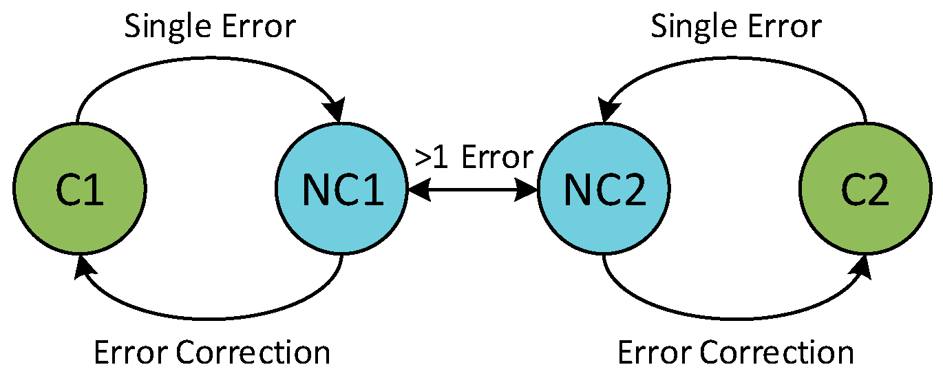
k) is the number of parity bits. A linear code simply means that the sum of any two codewords is another codeword. A Hamming code has a minimum distance of 3, which is the necessary condition for single error correction. This means that any codeword
C1 can change to non-codeword
NC1 when there is a single error in the codeword. Any other codeword
C2 can change to
NC2 but is never able to change to non-codeword
NC1 through a single error. Thus, whenever the non-codeword
NC1 is received, it can easily be decoded that the actual codeword stored was
C1. An illustration for this distance approach is shown in
Figure 1. In general, in order to correct
t errors, the code needs to have a minimum distance of (2
t + 1).
A Hamming code can be constructed based on a primitive generator polynomial of degree log
2(
n). Thus, if
n = 7, then the generator polynomial can simply be
g(
x) = 1 +
x +
x3. Alternatively, a parity check matrix can be used to construct the Hamming code. A parity check matrix (
H) is a matrix that defines the code and filters for codewords through Equation (1), where
cT is the transpose of a word. If the given word
c is a codeword, then the syndrome
S in this case will be 0.
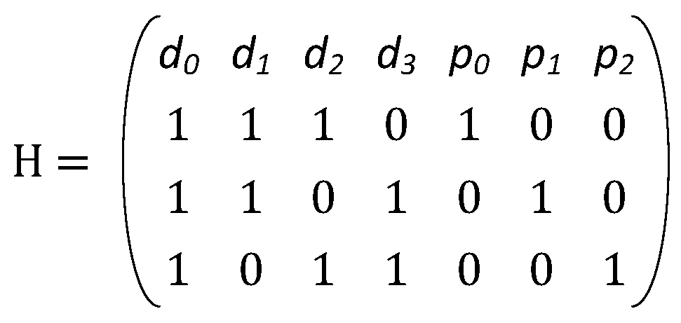
The construction procedure simply involves listing all possible columns of size log
2(
n), except the all-zero column. All columns with weight-1 are the parity portion of the matrix. The rest of the matrix represents the data portion. In order to compute the parity bits, the XOR of all the data bits, whose corresponding column value is 1 for a particular row, is computed. The parity portion of the H-matrix is ignored during code construction. An example of the parity check matrix for a (7, 4) Hamming code with its parity equations is shown in
Figure 2, where
d represents data bits and
p represents parity bits.
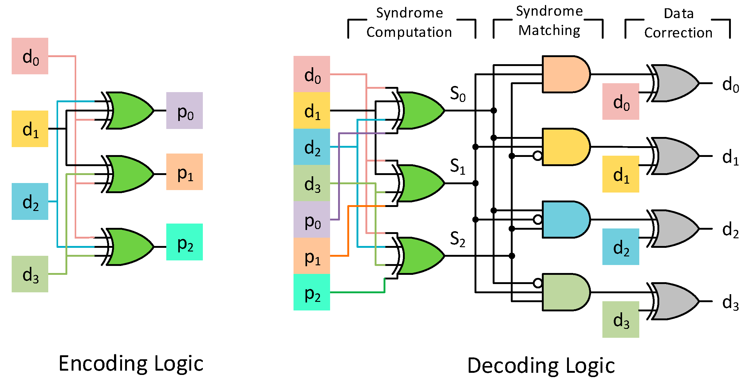
The encoding and decoding circuit of a (7, 4) Hamming code is shown in
Figure 3. The decoding procedure involves computing the syndrome, as shown in Equation (1). This essentially translates to a bunch of XOR operations between the stored data bits and the parity bits. If the computed syndrome is 0, then the codeword is non-erroneous and there is no need for any correction. For any single error, the syndrome bits will be identical to the column of the corresponding data bit that has flipped. Consider the code in
Figure 2 and assume that
d2 has an error. In that case the new word
y can be represented as the actual codeword
c added with an error vector
e. The error vector
e has an entry of 1 only at the 3rd position since bit
d2 is in error, as shown in Equation (2). The syndrome of this word is now the syndrome generated from the error vector, since the syndrome of a codeword is 0, as shown in Equation (3). Thus, any single error is identified by the syndrome it produces. The decoding procedure then involves matching the syndrome to the corresponding columns of a data bit, as shown in
Figure 3.
2.2. Orthogonal Latin Square Codes
OLS codes are based on Latin squares and use a majority voter for their decoding procedure [
6]. A Latin square of size
m is a
m ×
m square matrix such that the rows and columns of the matrix are a permutation of the numbers 0 to (
m − 1), and each number only appears once in each row or column. Two Latin squares are orthogonal if, when superimposed on each other, they produce a unique ordered pair of elements in the new superimposed matrix.
The underlying principle of a t-error correcting OLS code is that there are (2t + 1) independent sources for re-constructing each data bit. These (2t + 1) independent sources involve the data bit itself and 2t parity check equations. The different data bits participating in the parity check equations are unique in the sense that any data bit occurs at-most in one of the parity check equations. Thus, for any number of errors ≤ t, at-most t sources are corrupted. The remaining (t + 1) sources remain uncorrupted from errors. A majority logic decoding simply picks the binary value which occurs in the maximum number of its inputs. As a result, the majority vote of (2t + 1) independent sources with t-errors still yields the correct data bit. OLS codes have k = m2 data bits, where m is the size of the orthogonal Latin square. The number of check bits is 2tm, where t is the maximum number of errors that the code can correct. OLS codes are modular in design, which means that to correct additional errors, adding 2m check bits for each error is sufficient.
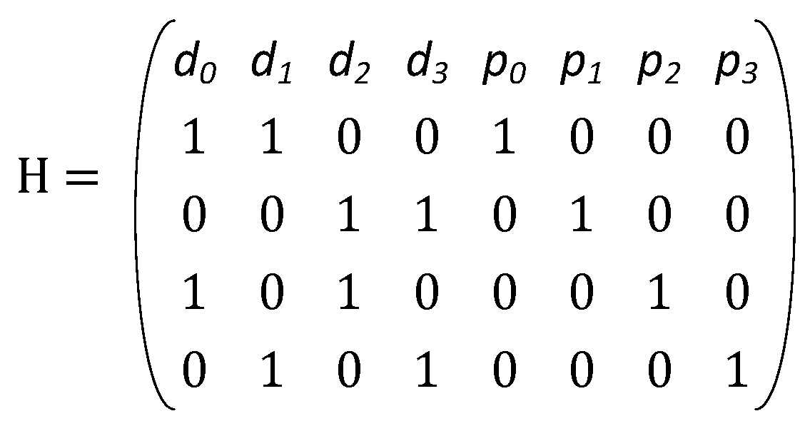
For a single error correcting code, only 2
m parity bits are required. An example of the parity check matrix for the SEC code for
k = 4 (i.e.,
m = 2) is shown in
Figure 4. Thus, in this case the majority voter chooses amongst 3 independent sources (one is the data bit and two more from parity equations), at most one of which can be corrected. An alternate decoding procedure involves computing the syndrome and taking the AND of the two syndrome equations any data bit is part of. This is because if a data bit is in error, it affects both its syndrome equations and thus the output of the AND gate is 1. If a data bit is not in error, it can at most corrupt one of the outputs of the AND gate, thus resulting in a 0. The output of the AND gate is then XORed with the data bit to produce the correct output.
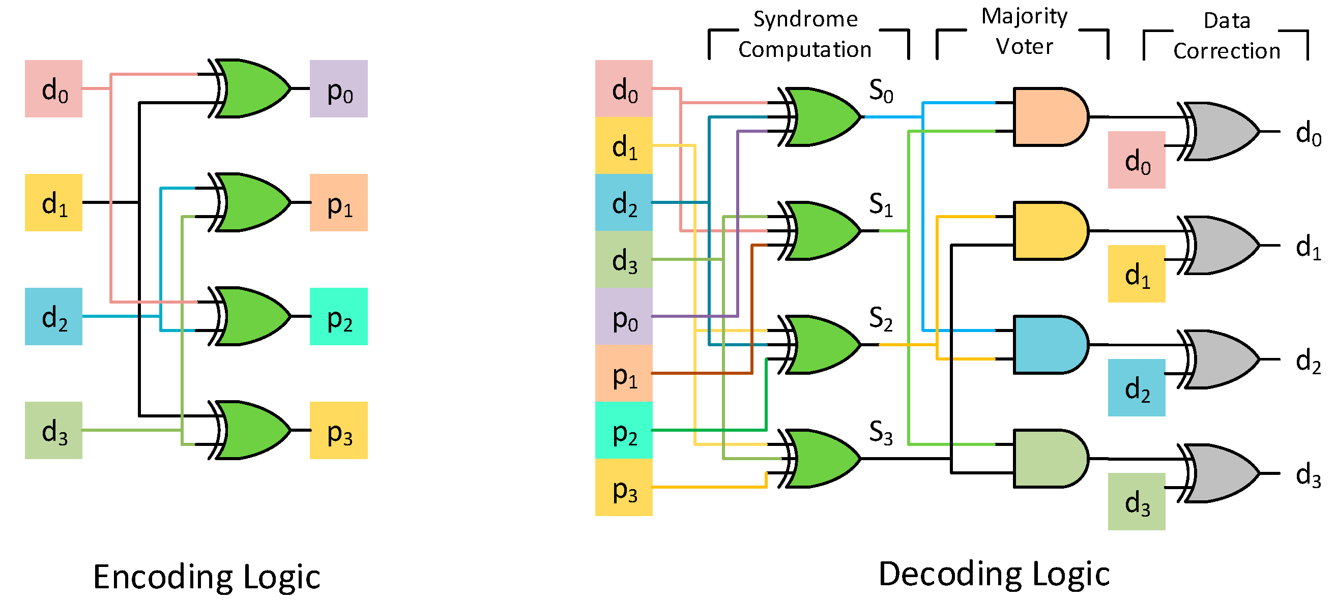
The encoding procedure involves the computation of parity bits. This is the XOR operation of all the data bits which are 1 in the row of the parity check matrix for which the parity bit is 1. The decoding procedure involves the majority vote between the data bit itself and the 2
t parity check equations constructed from the rows of the parity check matrix. Thus, the decoder for data bit
di will have parity check equations from each row of the parity check matrix for which the column
di is a 1. The main advantage of the OLS codes is the simplicity of the decoder circuit, which makes it very useful for memories with random accesses. The majority logic decoding circuit has very low latency thereby increasing decoding speed and enabling faster read operations. The encoding circuit and alternate decoder logic for each bit in
Figure 4’s parity check matrix is shown in
Figure 5.
3. Proposed Codes
The key idea of the proposed codes is based on repeating the data portion of the parity check matrix of a binary single error correcting orthogonal Latin square code. By design, the parity check matrix of a single error correcting OLS code will have all unique columns in order to identify and correct all single errors. However, by repeating a SEC OLS code, let’s say for example r times, the number of non-unique or repeated columns is now r. Thus, if any of the corresponding data bits of the r repeated columns is in error, then the syndrome will be the same. A simple majority in this case would actually then mistakenly flip all the data bits corresponding to the repeated columns.
To alleviate this issue of mis-correction, we introduce the notion of groups. A group is a single data portion of the parity check matrix which does not have any repeated columns within itself. Thus, within a group, all columns are unique. This essentially ensures that any single error within a group can easily be identified and corrected. Since there can be non-unique columns between different groups, we introduce additional rows in the parity check matrix to differentiate between different groups. The total number of additional parity bits needed for this purpose is given by pg = ceiling (log2 g), where g is the total number of groups. Thus, if any parity check matrix is repeated r times, then g = r+1.
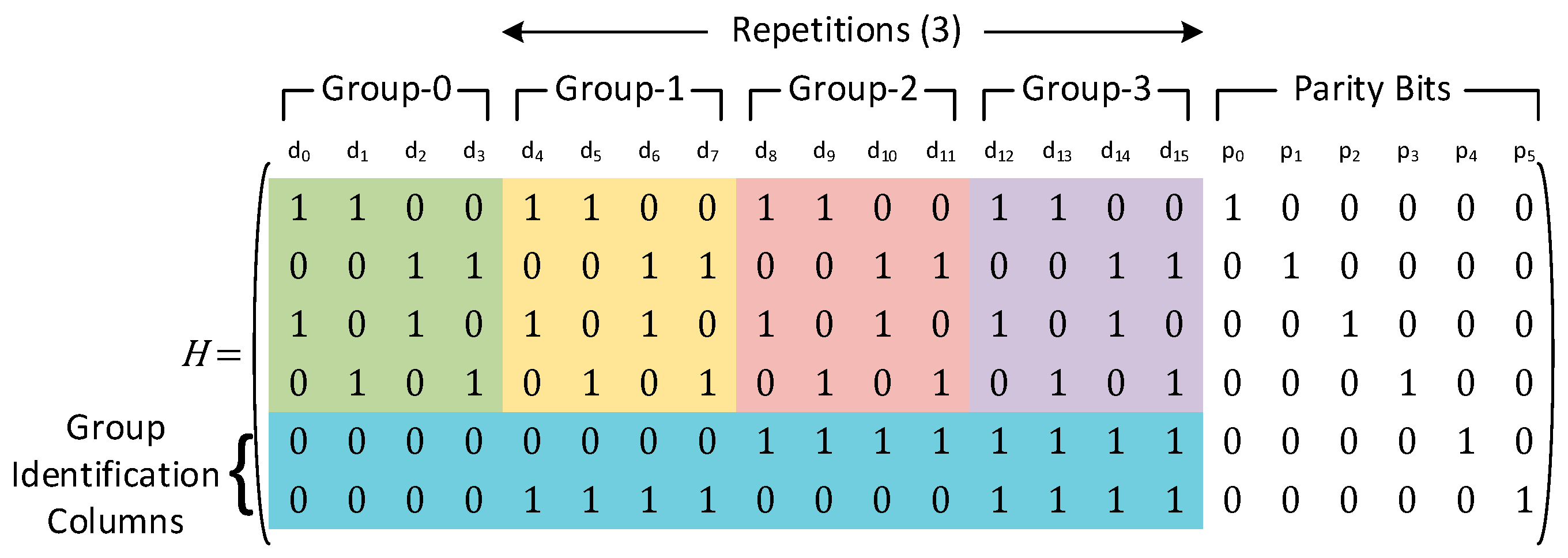
An example of a parity check matrix with number of data bits
k = 4 and a repetition of three is shown in
Figure 6. In this case, the different groups have been placed inside the differently colored boxes. The lower two rows (inside the blue box) are used to identify which group the error belongs to. The total number of data bits that can be protected using the above configuration is 16.
As an example, let’s consider that data bit
d4 is in error. The corresponding syndrome bits for this error is given by Equation (4). Now, if any of the data bits
d0,
d8 or
d12 are in error instead of
d4, the syndrome bits
S0:
S3 will still be the same. Thus, a simple majority vote in this case is not sufficient to identify the erroneous bit. Instead, an additional column match is required, apart from the majority voting logic, to identify which group the error belongs to. Matching the syndrome bits
S4:
S5 to the lower two rows of the parity check matrix indicates that the error must lie within Group-1. Since all columns within a group are unique, once the group within which the error has occurred is identified, a majority vote can capture which data bit is in error. Thus, taking a majority vote for each data bit in Group-1 yields the correct data and flips the erroneous bit
d4.
Thus, the proposed codes share the same majority voter for the data bits corresponding to the repeated columns across all groups. The group identification is done by matching the syndrome bits to the bits in the lower pg rows (i.e., group identifying bits), similar to the syndrome matching-based decoding of Hamming codes. We discuss the detailed encoding and decoding procedure in the subsequent subsections. The detection of double errors is not the focus of the paper, since to facilitate a double error detection mechanism, a parity bit computed from the XOR of all the data bits is enough. In all types of codes, if the syndrome corresponding to this parity bit is zero, while other syndrome bits are non-zero, then a double error has occurred, and an uncorrectable error flag can be raised. This is true for traditional Hamming codes and orthogonal Latin square codes, and the same mechanism can be used for the proposed codes as well.
3.1. Encoding Procedure
The encoding procedure is similar to that of a regular orthogonal Latin square code. In the parity check matrix, we consider each row one at a time. The row assigns the corresponding parity bit, which is 1, to the particular row. By design, any row has exactly one of the parity bits as 1. The parity bit value is the XOR operation of all the data bits whose corresponding column value is a 1 for the particular row. As an example, consider the parity bit
p0 in
Figure 6. In order to compute
p0, we look at all the columns that are 1 in the first row, which is given by Equation (5).
In terms of hardware resources, the parity bits can be computed by taking the XOR of the corresponding data bits. Thus, the parity bits can be constructed in a single step or single cycle. The parity bits can then either be appended to the original data bits and stored in memory, or they can be stored in a separate location relative to the address of the data bits being stored. The total number of parity bits
p for
k data bits and
R repetitions of the base parity check matrix is shown in Equation (6). The total number of data bits protected by these
p bits is
k(
R + 1).
3.2. Decoding Procedure
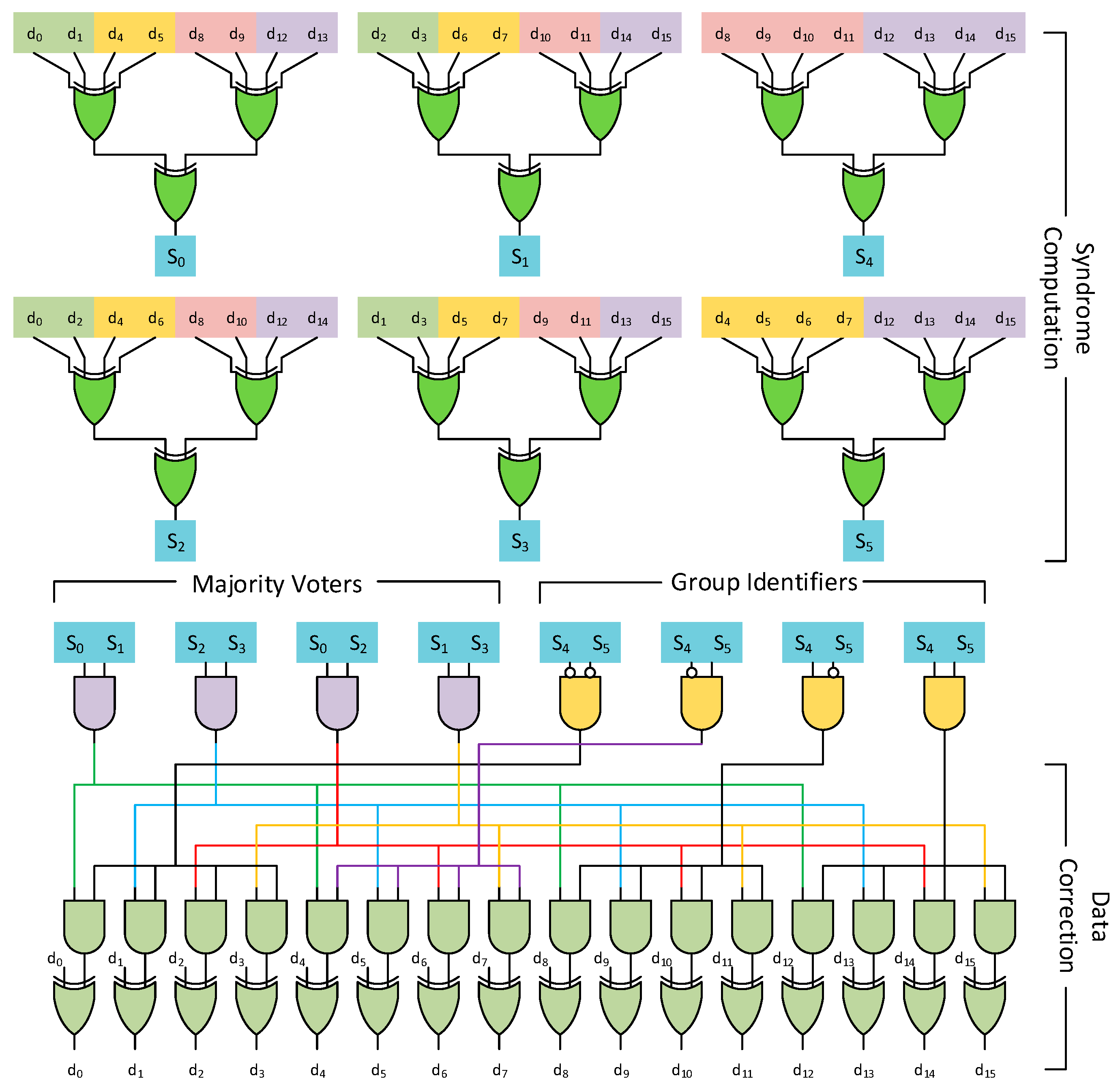
An example of the decoding circuit for the parity check matrix in
Figure 6 is shown in
Figure 7. The decoding procedure involves an additional step compared to traditional orthogonal Latin square codes to identify the group in which the error lies. This group identification is done using direct syndrome matching for the additional lower
pg rows added during the construction procedure. This is done in parallel for each group and is ANDed with the majority voting circuit for each column within a group. Thus, all columns within a group share the same AND output based on the lower
pg rows. In addition, identical columns across groups share the same majority circuit based on the base orthogonal Latin square code.
The above procedure leads to much lower redundancy due to the shared nature of parity bits. In comparison to a traditional OLS code, which would have had 16 majority voting circuits, i.e., one for each data bit, the proposed codes have 4 majority voters belonging to the base code, which are shared across groups. The disadvantage of such a method is that it increases the logic depth of the circuit, which leads to a slightly higher latency compared to traditional orthogonal Latin square codes.
3.3. Comparison to Hamming Codes
Hamming codes have the advantage of providing low redundancy but come at the cost of higher decoding latency. Part of the decoding latency is caused by the syndrome matching-based decoding which, depending on the number of bits being protected, can reach very high logic depths. By contrast, for the proposed codes, the majority voting circuit always has a fixed depth regardless of the number of bits being protected. The syndrome matching of group identification bits is limited by the number of groups in the proposed codes.
We can strike an adequate balance between the number of groups and the size of the base orthogonal Latin square codes to enable lower latency and high throughput. This leads to the proposed codes having a higher redundancy (or higher number of parity bits) but a lower decoding latency compared to Hamming codes. The proposed codes are highly configurable, and depending on the application requirements, can be configured to have either low memory overhead (redundancy) or lower decoding latency to enable high throughput.
3.4. Latency Optimization
For the proposed codes, the parity bits involved in group identification can have significant logic depth in their syndrome computation portion. This is because the proposed codes use log2(g) bits to identify the potential group that the error might lie in, where g is the total number of groups. This leads to a high number of data bits being involved in a single parity bit computation. The maximum number of data bits involved in such a parity computation can be 50% of all data bits, i.e., the parity bit might involve XORing 50% of all data bits in the message. This high logic depth can cause a bottleneck in terms of performance or throughput enhancement.
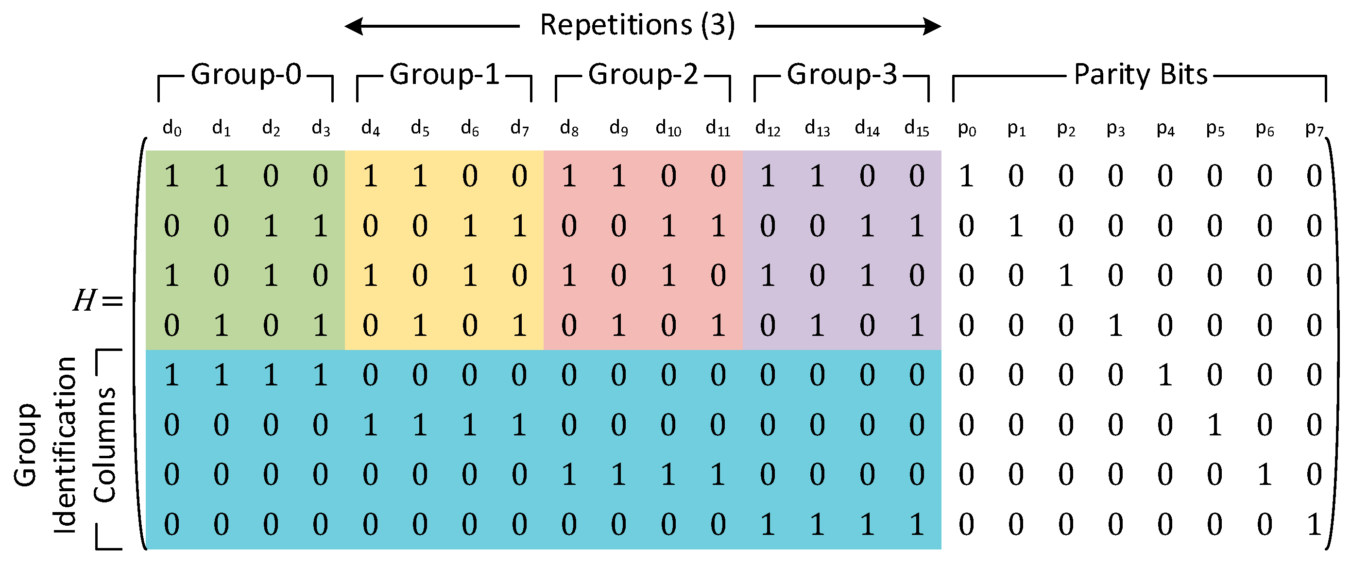
For cases where the number of groups is more than two, the performance can be enhanced by trading off a certain amount of redundancy. Instead of using log
2(
g) bits, we use
g parity bits to identify each group individually. This ensures that the maximum number of data bits that are XORed for group identification purposes is limited by the total number of data bits in any group. This leads to an increase in redundancy, since more parity bits now need to be stored to identify the group that is in error. However, this latency optimization scheme ensures that the maximum logic depth in the syndrome computation step is much less. An example of the parity check matrix for such a latency optimized code with 4 groups and 16 data bits is shown in
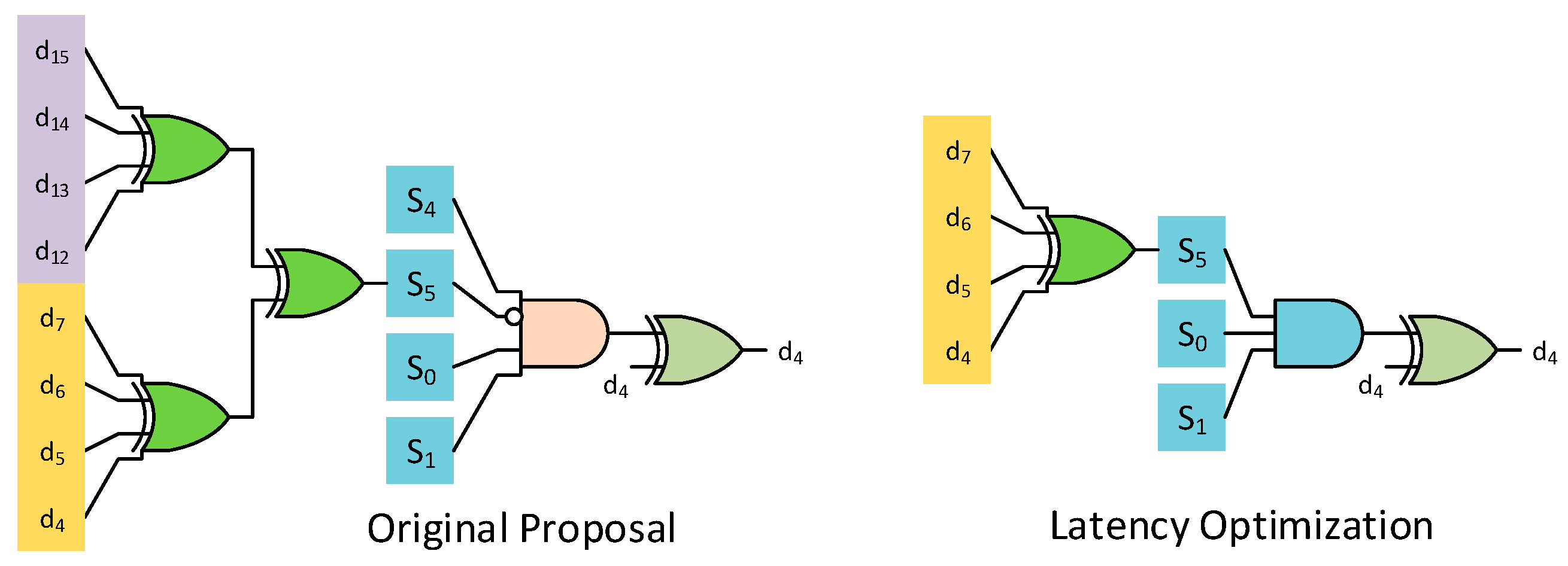
Figure 8.
The group identification combinational circuit will now instead be given by a single bit instead of the combination of parity bits corresponding to the lower log
2(
g) rows. The difference between this proposed latency optimization and the original proposal for data bit
d4 of the parity check matrix in
Figure 8 is shown in
Figure 9.
An analysis for latency optimization is presented next to illustrate the latency benefit obtained. The latency optimization comes from two parts. The first part involves the maximum number of inputs needed to compute the syndrome bits. Let us consider
k data bits in the base group and
g groups in the proposed codes. For the unoptimized proposal, at least 50% of the groups have all 1s (since the LSB of the log
2(
g) bits used for group identification switches between 0 and 1 for every group). Thus, the critical depth for syndrome computation will have the number of inputs as the maximum of either the repeated data bits for general parity bit or the parity bits from the group identification column, as shown in Equation (7). Comparatively for the latency optimized case, each group has its own parity bit. Thus, the maximum number of inputs for syndrome computation is given by Equation (8). To illustrate the difference, let’s consider an example with
k = 256 and
g = 4. This results in a total of 1024 bits being protected. The maximum number of inputs to syndrome computation for the unoptimized case will be 2 × 256 = 512. For the latency optimized case, this will only be 4 × 16 = 64.
The second part of the latency optimization involves data correction, as shown in
Figure 9. For the unoptimized case, since multiple groups can have 1s in them, all the bits are involved in data correction. Thus, the maximum number of inputs involved in computing the final decision (i.e., whether the bit has flipped or not) will include two syndrome bits from the base OLS code and all the bits from the group identification column, as shown in Equation (9). Thus, it is a function of the total number of groups. Comparatively, for the latency optimized case, the total number of inputs will always be three, since each group has its own syndrome bit. Thus, errors in any other group will not change this syndrome bit, and it can be used in decoding.
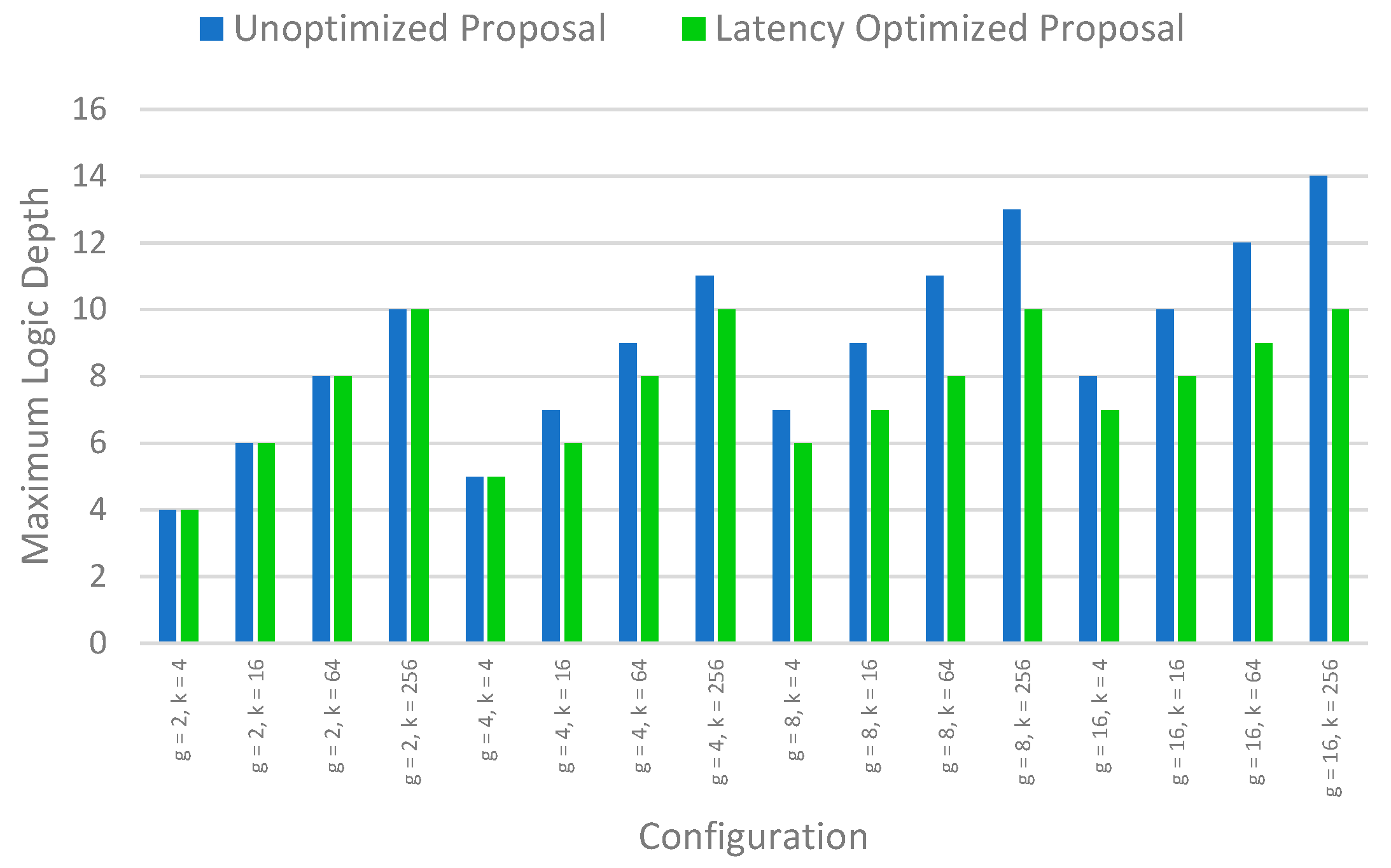
Assuming only 2-input gates and inverters integrated into the two inputs cases, i.e., inverters are not a separate depth, the total logic depth for the unoptimized case is given by Equation (10), while that for the latency optimized case is given by Equation (11).
Figure 10 shows the logic depth comparison for the unoptimized case and latency optimized case for different values of base data bits
k and different groups
g.
4. Evaluation
The proposed codes are evaluated against both Hamming codes and OLS codes in this section in terms of data redundancy (memory overhead), encoding latency, encoder area, encoder power consumption, decoder area, decoder power consumption and decoding latency. All the codes have been implemented using the Dataflow model in Verilog and have been exhaustively tested for correct functionality. The codes were also synthesized using the Open Cell library in 15 nm FreePDK technology [
16] using Synopsys Design Compiler. Comparisons have been made for both the encoding and the decoding circuit between Hamming codes, OLS codes, the basic proposed codes and the latency optimized proposed codes for different data sizes of
k = 32, 64, 128, 256, 512 and 1024 and different group sizes (or repetitions) of
g = 2, 4, 8 and 16 based on the number of data bits for the proposed codes.
Table 1 compares the encoding circuit of the different codes with different repetition values for the proposed codes. For OLS codes, all the parity equations are consistent, and each parity equation is a XOR of a fixed number of data bits which is equal to the size of the Latin square. Thus, the encoder has very low latency. However, they suffer from higher memory overhead (redundancy) due to the inherent structure of the code wherein fewer data bits are involved in each parity check equation. Hamming codes on the other hand have very low redundancy, but this comes at the cost of higher encoding latency, since more data bits are involved in each parity check equation, which increases the logic depth.
The proposed codes as well as the latency optimized proposed codes strike an adequate balance between the data redundancy and encoding latency when compared to OLS codes and Hamming codes. This is because the number of data bits participating in each parity check is more than in OLS codes, but either equal to Hamming codes (for original proposal) or less than Hamming codes (for latency optimized version). In all, from the experiments we see that the original version of the proposed code achieves up to 45% improvement in encoding latency compared to Hamming codes while achieving up to 68.75% improvement in memory overhead compared to OLS codes. Similarly, the latency optimized version of the proposed codes achieves up to 49% improvement in encoding latency compared to Hamming codes while achieving up to 50% improvement in memory overhead compared to OLS codes.
Table 2 compares the decoding circuit of the different codes. The amount of memory overhead remains the same for all cases. However, it can be seen that, similar to the encoding circuitry, Hamming codes are able to achieve the minimum memory overhead while incurring the highest decoder latency overhead. At the other end of the spectrum, OLS codes achieve very low decoder latency, but that comes at the cost of significantly higher memory overhead. The proposed codes achieve a balance between both the decoder latency overhead and memory overhead compared to Hamming codes and OLS codes. The original version of the proposed codes achieves up to 38% improvement in decoder latency compared to Hamming codes. The latency optimized version of the proposed codes achieves up to 43.75% improvement in decoding latency compared to Hamming codes.
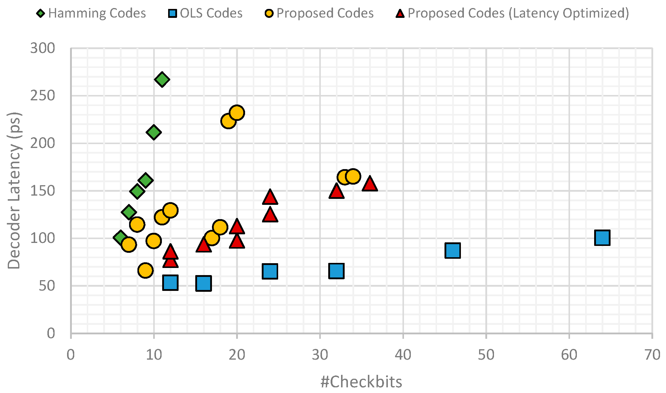
Figure 11 shows the comparison of memory overhead and decoder latency for the different codes across different numbers of data bits. As can be seen, Hamming codes provide the least memory overhead but that comes at the cost of high decoder latency. OLS codes instead have very low decoder latency but come at the expense of high memory overhead. The proposed codes, both the base version and the latency optimized version, provide a balanced trade-off between decoder latency and memory overhead.
From both
Table 1 and
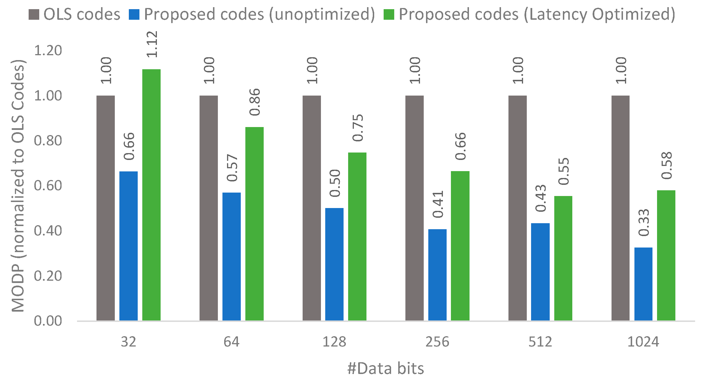
Table 2, it can be seen that OLS codes have an overall good performance in terms of latency, area and power consumption, but OLS codes do suffer from high memory overhead. The proposed codes focus on reducing the high memory overhead of OLS codes while still maintaining an adequate decoder latency to enable good performance. Thus, a memory-overhead delay product (MODP) metric is used to make this comparison.
Figure 12 shows the MODP comparison normalized to OLS codes (i.e., OLS codes will have a MODP of 1) for both the unoptimized proposal and latency optimized proposal. Since there are multiple possibilities of the number of groups for the proposed codes, the best MODP value is plotted against OLS codes. It can be seen that the proposed codes are able to achieve much better MODP compared to OLS codes, with the MODP as low as 0.33 times OLS codes. This is possible due to the low memory overhead of the proposed codes. The key takeaway from this figure is that the proposed codes are able to achieve much lower memory overhead without a corresponding significant rise in decoding latency.


