Article

A Hybrid PV-Battery/Supercapacitor System and a Basic Active Power Control Proposal in MATLAB/Simulink

by
Mustafa Ergin Şahin
1,* and
Frede Blaabjerg
2
1
Department of Electrical and Electronics Engineering, Recep Tayyip Erdoğan University, 53100 Rize, Turkey
2
Department of Energy Technology, Aalborg University, Pontoppidantstraede, 9220 Aalborg East, Denmark
*
Author to whom correspondence should be addressed.
Electronics 2020, 9(1), 129; https://doi.org/10.3390/electronics9010129
Submission received: 30 October 2019 / Revised: 18 December 2019 / Accepted: 3 January 2020 / Published: 9 January 2020
(This article belongs to the Section Power Electronics)

Abstract

:
An increase in the integration of renewable energy generation worldwide brings along some challenges to energy systems. Energy systems need to be regulated following grid codes for the grid stability and efficiency of renewable energy utilization. The main problems that are on the active side can be caused by excessive power generation or unregulated energy generation, such as a partially cloudy day. The main problems on the load side can be caused by excessive or unregulated energy demand or nonlinear loads which deteriorate the power quality of the energy networks. This study focuses on the energy generation side as active power control. In this study, the benefits of supercapacitor use in a hybrid storage system are investigated and analyzed. A hybrid system in which photovoltaic powered and stored the energy in battery and supercapacitor are proposed in this study to solving the main problems in two sides. The supercapacitor model, photovoltaic model, and the proposed hybrid system are designed in MATLAB/Simulink for 6 kW rated power. Also, a new topology is proposed to increase the energy storage with supercapacitors for a passive storage system. The instantaneous peak currents energy is aimed to store in supercapacitors temporarily with this topology. The main advantages of this topology are voltage stabilization in two sides by the supercapacitors and a limitation of the battery load, which directly results in longer battery life and decreases the system cost. The simulation results are investigated for this topology.

1. Introduction

The installation of grid-connected photovoltaic (PV) systems and building-integrated PV systems have continued to make rapid progress around the world in recent years. Increasing the PV penetration level in the low voltage (LV) grid brings several technical issues mainly related to power quality [1,2]. Here, problems are can be caused by excessive power generation or unregulated energy generation such as a partially cloudy day. The main problems on the load side can be caused by excessive or unregulated energy demand or nonlinear loads [3]. Supercapacitors (SCs) are proposed as a solution and used in some applications, and their effects on grids are investigated in many studies [4].
Photovoltaic panels are intermittent sustainable energy sources dependent on the environmental conditions which require energy storage to balance the generation and demand [5]. In contrast, SCs have a higher power density than batteries, allowing the SCs to provide more energy over a shorter period. Li-ion batteries have a low power density and slow charging/discharging rates, e.g., taking several hours for charging. The supercapacitors have been used to absorb the high-frequency power fluctuations from the PV and maintain the voltage of the DC link in a proper range [2]. SCs are also used in the power smoothing application of PV systems. The SCs are chosen to supply the fast-increased demand, e.g., within seconds. However, SCs cannot provide very high power. SCs are charged when energy demand is lower than the generation and store that energy [6].
Battery charge/discharge stress and their impact on battery’s health can be mitigated by different battery-supercapacitor topologies [7]. The high load current for an instantaneous power delivery elevates the discharge rate and current of the battery. This damages the battery more rapidly [8]. Supercapacitor in hybrid energy storage system (HESS) delivers instantaneous power. It aids in prolonging battery lifespan by catering for the peak power [9]. Increased battery capacity is required in a system that enables the motor to be started throughout the day without breaching the low voltage limit. This could result in a large battery pack, increasing the lifetime system cost. In general, batteries need to be replaced every 3–5 years [5]. The active HESS system allows both the battery and the supercapacitor to be operated at different voltages, allowing for better utilization of the individual components. An active HESS configuration makes the best use of the available supercapacitor energy [10].
Electrical energy from the grid is stored by the supercapacitor during off-peak hours and delivered back to the grid during peak hours for system stability, reliability and power quality improvement [11,12]. Through a reasonable energy storage control strategy, the charge and discharge of energy storage can be controlled dynamically, which will make it possible to balance the energy of power grids and optimize system operation [13,14]. The DC-link voltage of the DSTATCOM is regulated by the supercapacitor throughout the compensation process very quickly. The DC bus link capacitor is used in DC to AC inverters to decouple the effects of the inductance from the DC voltage source to the power bridge in some low voltage applications. The DC-link capacitance of inverters replaced with supercapacitor module for low voltage applications is more reliable, but also more expensive and larger than film capacitors [7]. The investigated studies have shown that the SCs used with the hybrid PV–battery system are indispensable for the energy system, but this requires more detailed researches.
The comparison of SCs with the other storage devices [2,5,7], and the advantages are investigated for hybrid PV-battery SCs systems in the literature [9,10]. These systems will be presented and discussed in future sections. Also, the hybrid energy storage systems (HESS) such as PV–battery supercapacitors or fuel cells are proposed as a different solution in some studies [11,12,13]. Most studies are focused on load control and share the demand with these hybrid systems. The PV side active source control studies for the hybrid systems are investigated very rarely. HESSs are classified as passive, active, and semi-active topologies according to the connection of storage devices to DC bus [7,14].
In this paper, the advantages and disadvantages of SC use in a hybrid system are investigated and analyzed. A hybrid storage system in which photovoltaic powered and stored the energy in battery and supercapacitor are proposed in this study to solving the main problems in load and source side. The supercapacitor model, photovoltaic model, and the proposed hybrid system are simulated in MATLAB/Simulink for 6 kW rated power. Also, a new topology is proposed to increase the energy storage with supercapacitors for a passive storage system. The instantaneous peak currents energy is aimed to store in supercapacitors temporarily with this topology, and the simulation results are investigated.

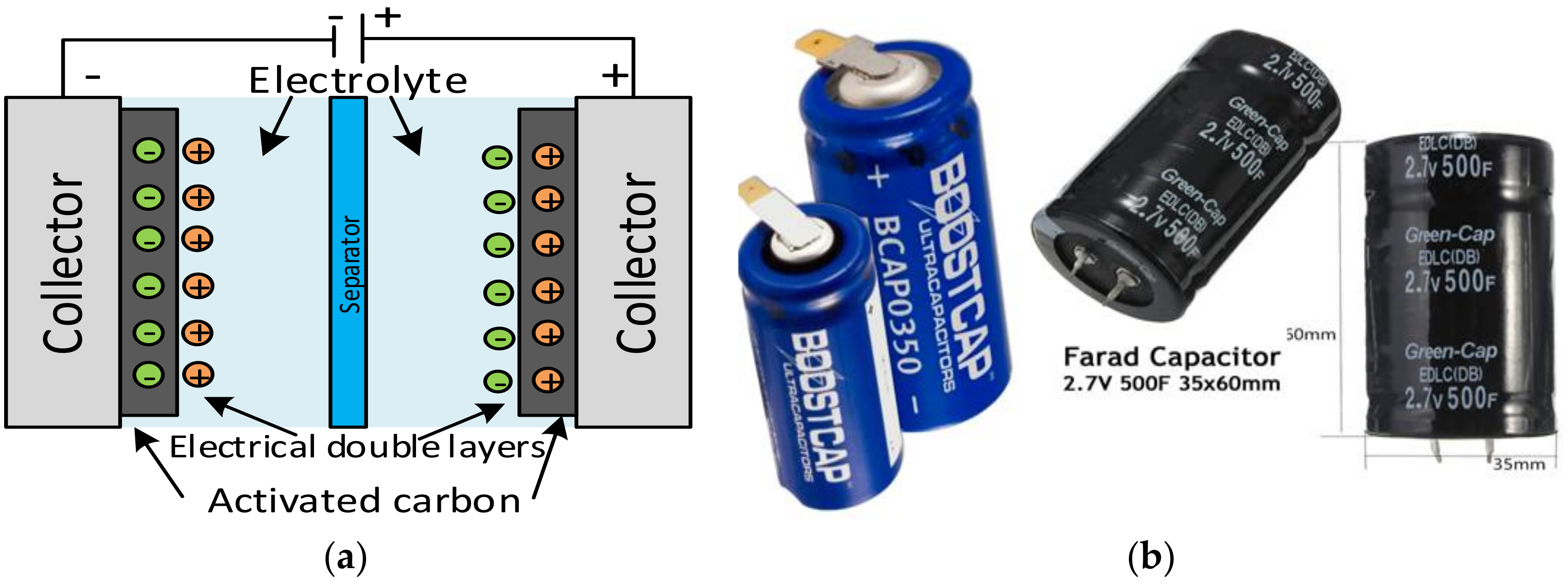
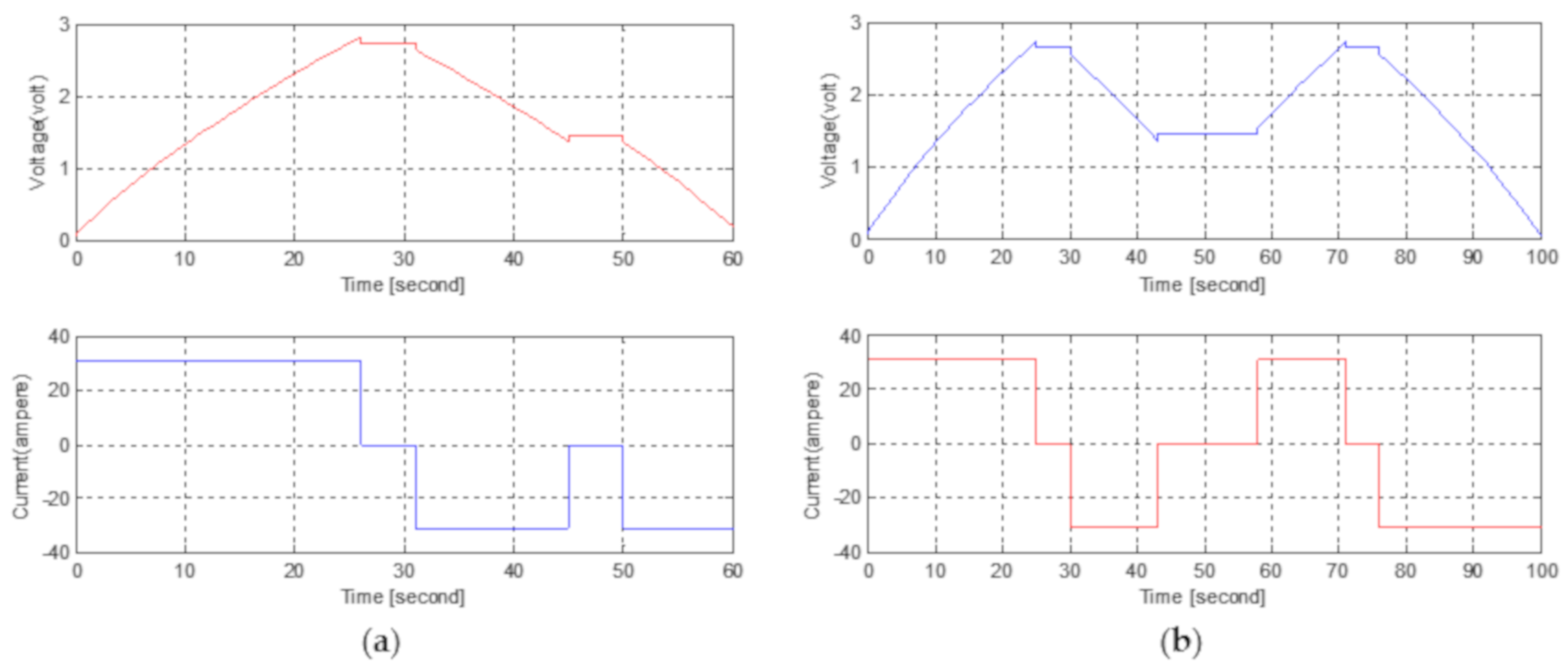
2. Investigation of Supercapacitors

In this section, the chemical structure, advantages, and disadvantages of supercapacitors, basic specifications, as well as a performance comparison of SCs with Lead-acid and Lithium-ion batteries are given. A comparison of various electrochemical storage devices for energy density, power density, and other main characteristics are given in this section.
Unlike a ceramic or electrolytic capacitor, a supercapacitor does not have a dielectric material. Instead, it uses the electrical double layer (EDL) that is formed at the interface of the solid electrode and liquid electrolyte. One of these layers is the Aluminum layer and the other is the activated carbon layer. A typical supercapacitor is composed of solid electrodes, liquid electrolytes, including electrolyte salt, and a separator to prevent contact between the positive and negative electrodes. The electrodes are positioned on the electricity collectors and coated with activated carbon powder. An electrical double layer is formed at each interface where the active carbon powder contacts the electrolyte. When the SC is charged, the negative ions and vacancies on the positive electrode side and the positive ions and the electrons on the negative electrode side are aligned across the interface. This state of alignment of ions and electrons is called an electrical double-layer capacitor (EDLC) and the structure is shown in Figure 1a [15]. Some SCs that can be obtained on the market are given in Figure 1b [16].
The advantages and drawbacks of supercapacitors are combined and summarized in Table 1 to be compared easily [5]. The advantages of supercapacitors make them superior to other storage devices in many ways, although they have some drawbacks. Therefore, use them together with the other storage devices in some applications is looking reasonable [7].
The performance analyses of lead-acid, lithium-ion batteries, and supercapacitors are compared in Table 2 [7,13,15,18,19]. The advantages and drawbacks are shown clearly in this comparison table.

3. Hybrid Energy Storage Systems

The comparison of supercapacitors with the other storage devices shows that use the supercapacitors with the other storage devices offers some advantages [2,5,7]. These advantages are investigated for hybrid PV–battery supercapacitor systems in the literature [9,10,13]. Some of these advantages are given in previous sections. The other will be presented and discussed in these and the future sections. Also, hybrid energy storage systems (HESS), such as PV–battery supercapacitors or fuel cells, are proposed as a different solution in some studies [11,14]. Most of the studies are focused on load control and share the demand with these hybrid systems. PV side active source control studies for the hybrid systems are investigated very rarely.
The HESS are classified passive, active and semi-active topologies according to the connection of storage devices to DC bus. If the storage devices are connected directly to DC bus it is called passive HESS as shown in Figure 2a. If one of the storage devices is connected with a bidirectional DC-DC converter to DC bus it is called semi-active. If two of the storage devices are connected with a bidirectional DC-DC converter to DC bus it is called active HESS. A standalone semi-active or active hybrid energy storage system is prosed by Jing et. al. as a case study is given in Figure 2b [7,14,19]. In this system, PV power is controlled by an MPPT charge controller and energies the DC microgrid. If the hybrid energy storage system is connected to the DC bus with a controller or energy management system for two bidirectional DC-DC converters, this topology is called active HESS as shown in Figure 2b [7]. The bidirectional converters are supplied to store the energy in battery and supercapacitors from PV in one way and supply the loads from battery and SCs in another way.
In a case study, the active and passive HESS systems are simulated and compared for battery lifetime and healthy cost during a day. The supercapacitor semi-active HESS systems perform lower than 33% battery only case and passive HESS systems perform only lower than 9% battery case cost function result during a day [7,14].
Another study investigated the annual storage cost. Therefore, the solar irradiance and temperature data from four diverse days from 2017 are used in this simulation in MATLAB/Simulink solar farm model. A cell temperature estimation algorithm is used for PV modules’ realistic temperatures. The price comparison between two kinds of the energy storage system, (i) Battery only (ii) HESS, Li-ion battery, and supercapacitor combination, are shown in Table 3 [20]. The simulation results show that the lowest prices are in January, and the energy storage system cost is 25% cheaper for Battery + SC HESS annually.
The optimum sizes of the system that meet the load profiles at the proposed site, given conditions of renewable energy resources and based on components datasheet, can be simulated using hybrid optimization model for electric renewable (HOMER) tool software. HOMER provides the results in terms of optimization and sensitivity analysis for different parameters of the power system [21].

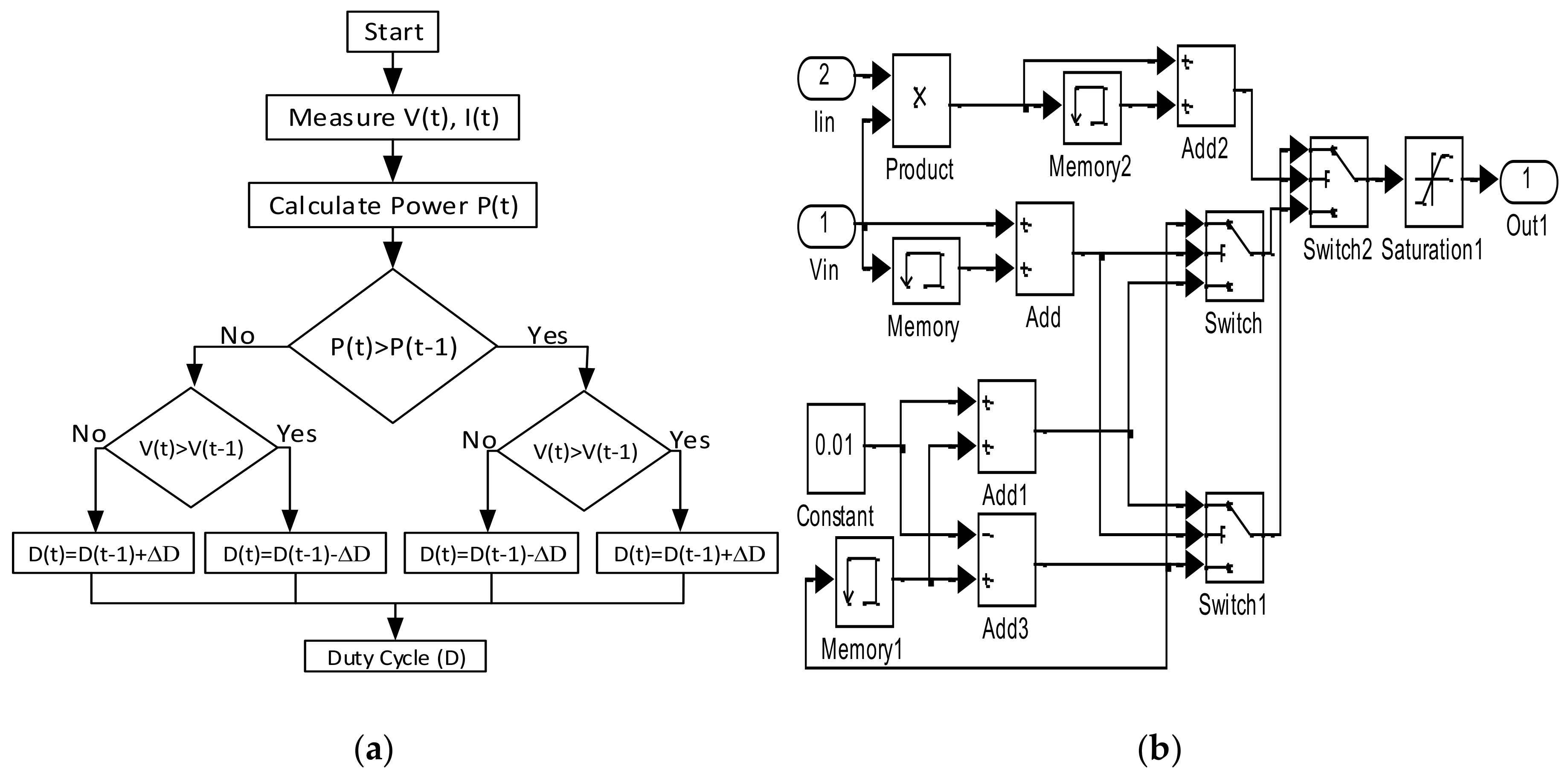
4. Proposed Controller for Hybrid Energy Storage System

Energy storage refers to a broad category of technologies and applications that can help utilities balance power supply and demand by holding energy for later use, like a bank account for energy. Storage technologies are distinguished primarily by capacity and discharge time. Different storage technologies can be used for each of the three main electric sector goals: energy management for daily/hourly scheduling, operating and ramping reserves for load following, and frequency response and regulation to maintain power quality. High power SCs store energy within seconds and are used for frequency response and regulation. The potential and extensive grid applications of SCs are deferred system inertia and smooth output for transmission and distribution and the maintenance of power quality for end-use [1].
In contrast, the installation of grid-connected photovoltaic (PV) systems has been increasing to introduce more renewable energy into the mixed power grid. As the penetration level of PV systems further increases, its integration into the power grid becomes important. In the case of wide-scale PV system installations, the grid may face challenges like overloading during peak-power generation periods, voltage fluctuations due to the intermittency of solar energy, and limited frequency regulation capability [1,18]. The active power control is categorized into three main functionalities:
  • Power Limiting Control (PLC)
  • Power Ramp-Rate Control (PRRC)
  • Power Reserve Control (PRC)
Examples of these active power control strategies are defined in the Danish grid code [22].
At this point, hybrid energy storage systems with supercapacitors, and their effects on the grid and active power control, are proposed in this paper as a solution to increase system reliability. This proposal aims to combine two storage system advantages and supply to grids and loads uninterruptedly [23,24]. Also, this proposal aims to increase the efficiency of active power control strategies at the same time. The proposed new topology and control of the passive HESS is given in Figure 3. In this topology, the PWM signal generation method is used for peak shaving control. The PV voltage variation is compared with a peak shaving reference similar to the PWM signal generation error signal. Two switching signals are obtained as a result of this comparison (SPWM, NOT SPWM). The switching signal (SPWM) is used to activate the battery charger unit, and the reverse of the switching signal (NOT SPWM) is used to activate the supercapacitors charge unit. The main idea of this proposed method is to store the instantaneous currents with supercapacitors in partial cloudy days. In this way, the instantaneous peak energy values are stored in the supercapacitors in a short time and can be used or transferred after. This method is very effective for cloudy weather days.
The active power control strategies for HESS and grid-connected PV systems with supercapacitors is a case study in this paper. The power control strategies with supercapacitors and their estimated possible advantages are given in Table 4. These comments are interpreted with theory and there are very few studies on this subject and they should tray [25,26]. A more detailed comparison will be presented in the future as a case study.

5. Modeling of Hybrid Storage System and Components

For SC systems, modeling is essential for the system dimensioning, condition monitoring, and controller design. Several SC models are available in the literature based on; chemical, mathematical and electrical characteristics, aging, artificially intelligent, and the dynamic structure of SCs models [27,28,29,30,31,32,33,34]. A simple electrical model of SCs to describe the behavior of SCs as a function of frequency, voltage, and temperature has also been discussed in [35]. The module simulation was based on a supercapacitor two-branch circuit model, which also included the module structure and its mathematical equation simulation [34,35,36]. This circuit is a simplified neglected leakage current of supercapacitor and can be given in Equation (1) for the SC module. The USC and ISC are the supercapacitor module voltage and currents respectively. The vsc and isc are the supercapacitor primary voltage and current, respectively [36].
U S C = N S _ S C v S C = N S _ S C ( v 1 + R 1 . i S C ) = N S _ S C ( v 1 + R 1 I s c N P _ S C )
On the other hand, the relationship between capacitor charge (Q1) and voltage (v1) is shown in Equation (2). The equivalent electric circuit with two RC branches proposed by Zubieta and Bonert [35] and Rafik et al. [36] was used to obtain this equation.
v 1 = C 0 + C 0 2 + 2 C V Q 1 C V
Equations (1) and (2) are combined as in Equation (3).
U S C = N S _ S C v S C = N S _ S C ( v 1 + R 1 . i S C ) = N S _ S C ( C 0 + C 0 2 + 2 C V Q 1 C V + R 1 I s c N P _ S C )
These equations are designed in MATLAB/Simulink as an SC module model as shown in Figure 4. Equations (2) and (3) are modified for 310 F capacitor coefficients in the simulation. These coefficients are obtained and calculated in previous studies experimental values and datasheets [37]. These values are R1 = 5.5 mΩ, R2 = 6 Ω, C0 = 210 F, CV = 80 F/V, C2 = 39 F. Further, an SC electrical model for the simulation of power systems is shown in Figure 4.
The supercapacitor model is simulated and checked for CAP/ESR measurement and cycle life waveforms in the datasheet [38]. The simulation result for CAP/ESR measurement waveform is shown in Figure 5a and the cycle life waveform is shown in Figure 5b. The simulation results suitable with experimental results which is proof that the SC model works correctly.
The other main component of the hybrid system is the PV source. The PV module was designed and simulated in some previous studies. The solar cells are connected in series and parallel to obtain photovoltaic module model [39,40,41]. The PV module current equation is given in Equation (4), but this equation does not include all the parameters such as temperature and solar irradiation. Also, the temperature and solar irradiation equation are added, and this total model voltage equation is given in Equation (5) [42,43].
I = N P . I P H N P . I 0 exp q V N S + I . R S N P / k . T C . A 1 N P . V N S + I . R S / R S H
V P V = N S . n . k . T q ln ( I S C + K I ( T T r e f ) ) . G + N P I 0 I P V I 0 . N P N S N P . R s R s h . I P V
For the PV module design, Equation (5) is used and the MATLAB/Simulink model is obtained as in Figure 6. The simulation parameters are selected from data sheets of BP-MSX120 panels produced by BP Solar [38,43]. The PV module is adjusted as an array (5 series × 10 parallel) for 6 kW PV MPP power and high voltage value for simulations. The I-V and P-V curves of the 6 kW PV array model are presented in Figure 7a,b.
The other main component of the photovoltaic system is the maximum power point tracker (MPPT), which is used to harness maximum power from the PV due to its nonlinear characteristics and low efficiency. Perturb and observe (P&O) is one of the MPPT methods used in solar PV systems [44,45]. The P&O method algorithm and MATLAB/Simulink model are shown in Figure 8a,b. The method basically measures the PV voltage and currents to calculate the maximum power. If the power last value is bigger than previous compared to the voltage last value with the previous. If the last voltage value is bigger than the previous value, the duty ratio (D) is increased one step, or is decreased one step. In this way, an optimum duty cycle is obtained to drive the converter to works on MPP.
The newly proposed topology with the hybrid energy storage system is simulated in MATLAB/Simulink basically as shown in Figure 9. The passive HESS simulated for DC grid side for new topology and peak shaving active power control firstly [19]. The PV model is simulated for random irradiation (Sx) values and a maximum 6 kW power and PV array model connecting with an MPPT controller [46,47]. The obtained signal from MPPT is converted to a switching signal to drive the boost converter on the output of the PV array. The DC output of the converter connected with the SC model and battery model with two switches. These switches are driven by a signal obtained from the comparison of PV input voltage with peak shaving reference. All the simulation parameters for the HESS are given in Table 5.

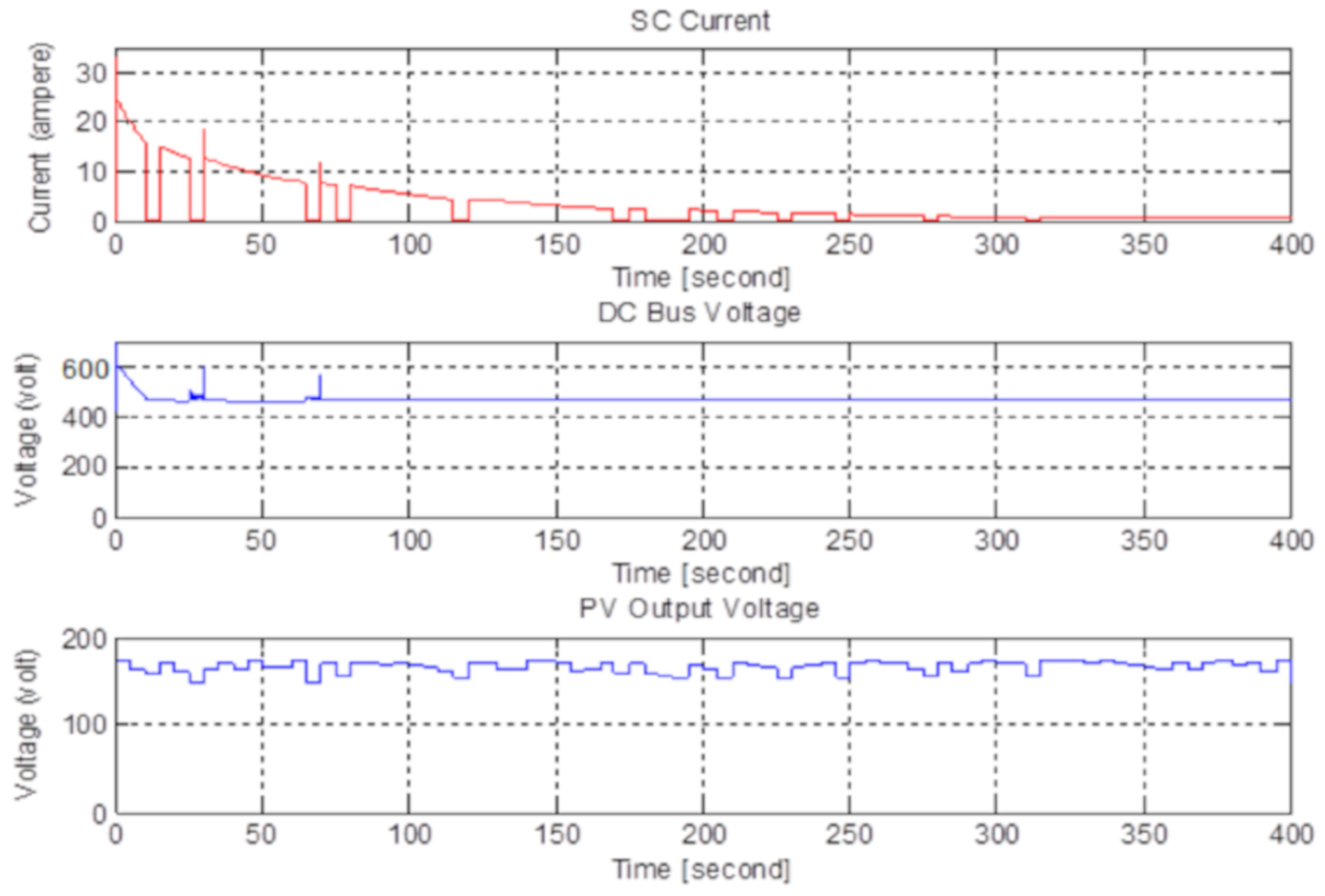
6. Simulation Results

The PV array model is designed according to manufacturer catalogs and for 6 kW power, 50 (5 series × 10 parallel connected) panels are required, and the PV source parameters are designed to supply this energy from PV panels. The PV output voltage which is fixed around the MPP and depends on the load of the boost converter, output voltage of the boost converter, and the switching signal which is obtained from MPPT output is shown in Figure 9. The simulation results show that the PV voltage is increased and fixed to the 220 V bus voltage. The simulation results of the solar irradiation (Sx), PV output voltage variation with time, supercapacitor, and battery switch signals for power-sharing are shown in Figure 10 respectively. Depend on the peak shaving reference signal, an SC switching signal (SM1) will be generated on the voltage peak time and will supply the current flow in supercapacitors. During the other period, a battery switch signal (SM2) will be generated and will be supplied to the power flow in the battery synchronously. With this topology, it will be possible to charge the instantaneous powers quickly in supercapacitors.
This simulation results in Figure 10 and Figure 11 are as expected in theory. The PV voltage is fixed in MPP voltage with small fluctuations thanks to MPPT and controller. The output voltage is constant with a small fluctuation in time similarly. Also, the converter switching signal duty ratio is seen as expected for a boost converter topology. The other simulation results in Figure 12 show that the proposed system is working correctly. Depending on the randomly generated solar irradiation between 0.1 and 1 kW/m2, the PV voltage is changed between 160 and 180 Volts. If the solar irradiation and PV output voltage are lower than the peak shaving reference, the supercapacitor switching signal (SM1) will be OFF and the battery switching signal (SM2) will be ON. Otherwise, it will be reversed as shown in Figure 12.
The supercapacitor modules are obtained by connecting five of the series and two of these series parts connected parallel in these simulations. So, I used 10 pcs in every module for the desired voltage and current. The simulation results of the supercapacitors in charge time from PV for the variable solar irradiation are shown in Figure 13. The supercapacitor is charged dashed mode with time and the voltage is increased step by step and becomes constant with time according to the proposed method for every module. The charge current decreases from the maximum value to zero in approximately 400 s. The charge current can be changed depending on the weather conditions. The multiplication of this voltage and current gives the charged power in a supercapacitor, and the area under the curve gives the stored energy in the supercapacitor module. These results must be modified for 20 series supercapacitor stacks for voltage and power. Further, maximum charged power is 6 kW for this stack. The total current of the modified supercapacitor module, the DC bus voltage, and PV output voltage variation are shown in Figure 14. The DC bus voltage is constant at 420 V with time as expected.
The simulation results of current variations for two different level PV voltage are shown in Figure 15. One of these voltages is bigger than reference and the current flows through the SC. The other is smaller than the reference voltage and the PV current flows through the battery. The total bus current shows all the current in two situations. The simulation results of voltage variations for three different level PV voltage are shown in Figure 16. The PV voltage changes in every five seconds steps depend on the solar irradiation. The DC bus voltage is increased up to 400 V voltage levels with the boost converter and MPPT+PI controller. The SC line voltage is equal to the bus voltage when the PV voltage is bigger than the reference voltage. The SC line voltage is equal to the charged level when the PV voltage is smaller than the reference voltage. In this state, the switch is off. The battery voltage is constant to the nominal voltage level with some small ripples.
The simulation results show that the new topology with passive HESS is suitable for the theory as expected. The simulation results show only the photovoltaic power-sharing by shaving the pick powers of PV in partially cloudy days. The peak shaving reference voltage can be adjusted depending on the capacitor’s energy storage capacity and weather conditions. This study is only a case study to show that instantaneous power can be stored by the supercapacitors more efficiently as active power control. By utilizing hybrid energy storage systems consist of battery-supercapacitor can be reduced the storage size and the overall stress on the battery, also higher SOC can be maintained. The use of a supercapacitor is shown to be able to increase the lead-acid charging capacity by more than 25% during sunny weather and 10% in cloudy weather [7,10]. The stored energy in supercapacitors is then released during the low solar radiation periods to charge the battery.

7. Conclusions

In this paper, the investigation of a hybrid PV–battery/supercapacitor system and active power control in MATLAB/Simulink for a new topology are presented in detail. Firstly, studies in the literature are investigated more detailed. The advantages and disadvantages of supercapacitors are investigated for active PV power control in this study. Supercapacitors used in active PV power control not will not have an extra price, because using in load side reduces the price of the storage system as has been proven. Also, using supercapacitors will reduce the prices in some extra aspects, such as by reducing battery aging and increasing efficiency. A new topology for HESS to share the PV power and to shave the PV peak power is proposed. The proposed passive HESS, which combined the PV module with MPPT and the supercapacitor module, was designed in MATLAB/Simulink. The simulation results show that this topology can be used for HESS to increase efficiency and can be applied experimentally. Different HESS topologies, control methods, and grid connections will be investigated in the future.

Author Contributions

Conceptualization, M.E.Ş. and F.B.; Funding acquisition, M.E.Ş.; Investigation, M.E.Ş.; Methodology, F.B.; Validation, F.B.; Writing-original draft preparation, M.E.Ş.; Editing and Supervision, F.B. All authors have read and agreed to the published version of the manuscript.

Funding

This study was supported through The Scientific & Technological Research Council of Turkey (TUBITAK), 2219 postdoctoral research program with a 1059B191700997 application number.

Acknowledgments

This study was made during the postdoctoral research of the first author in Aalborg University and the authors wish to thank for the support of TUBITAK. Also, the authors wish to thank Ariya Sangwongwanich from Aalborg University/Denmark for the contributions.

Conflicts of Interest

The authors declare no conflict of interest.

Abbreviations

The following abbreviations are used in this manuscript:
DSTATCOMDistribution static compensator
EDLCElectrical double layer capacitor
ESR-CAPCapacitor series resistance
ESREquivalent series resistance
HOMERHybrid optimization model for electric renewable
HESSHybrid energy storage system
LVLow voltage
MATLABMathematical laboratory software
MPPTMaximum power point tracker
PRRCPower Ramp-Rate Control
PRCPower Reserve Control
PLCPower limiting control
P&OPerturb and observe
PVPhotovoltaic
PWMPulse with modulation
SPWMSwitched pulse with modulation
SCSupercapacitor
SOCState of charge

References

  1. Energy Storage Possibilities for Expanding Electric Grid Flexibility. In Energy Analysis; National Renewable Energy Laboratory; IPO Publishing Ltd.: Bristol, UK, 2016.
  2. Khan, M.A.; Zeb, K.; Sathishkumar, P.; Ali, M.U.; Uddin, W.; Hussain, S.; Ishfaq, M.; Khan, I.; Cho, H.G.; Kim, H.J. A Novel Supercapacitor/Lithium-Ion Hybrid Energy System with a Fuzzy Logic-Controlled Fast Charging and Intelligent Energy Management System. Electronics 2018, 7, 63. [Google Scholar] [CrossRef] [Green Version]
  3. Xu, C.; Zhou, B.R.; Zhai, J.W.; Zhang, Y.J.; Yi, Y.Q. The active control strategy on the output power for photovoltaic-storage systems based on extended PQ-QV-PV Node. In Proceedings of the IOP Conference Series: Earth and Environmental Science, Kuala Lumpur, Malaysia, 24–26 April 2017; Volume 67, p. 012016. [Google Scholar]
  4. Zhang, L.; Hu, X.; Wang, Z.; Sun, F.; Dorrell, D.G. A review of supercapacitor modeling, estimation, and applications: A control/management perspective. Renew. Sustain. Energy Rev. 2017, 81, 1868–1878. [Google Scholar] [CrossRef]
  5. Glavin, M.E.; Hurley, W.G. Optimizations of a photovoltaic battery ultracapacitor hybrid energy storage system. Solar Energy 2012, 86, 3009–3020. [Google Scholar] [CrossRef]
  6. Buller, S.; Thele, M.; De Doncker, R.W.; Karden, E. Impedance-based simulation models of supercapacitors and Li-ion batteries for power electronic applications. IEEE Trans. Ind. Appl. 2005, 41, 742–747. [Google Scholar] [CrossRef]
  7. Jing, W.L.; Lai, C.H.; Wong, W.S.; Wong, M.D. Cost analysis of battery-supercapacitor hybrid energy storage system for standalone PV systems. In Proceedings of the 4th IET Clean Energy and Technology Conference, Kuala Lumpur, Malaysia, 14–15 November 2016. [Google Scholar]
  8. Mitkowski, W.; Skruch, P. Fractional-order models of the supercapacitors in the form of RC ladder networks. Bull. Pol. Acad. Sci. Tech. Sci. 2013, 61, 581–587. [Google Scholar] [CrossRef]
  9. Shrivastava, A.; Gupta, S. Review on Super Capacitor-Battery based Hybrid Energy Storage System for PV Application. Int. J. Adv. Eng. Manag. Sci. 2017, 3. [Google Scholar] [CrossRef]
  10. Logerais, P.O.; Riou, O.; Camara, M.A.; Durastanti, J.F. Study of photovoltaic energy storage by supercapacitors through both experimental and modeling approaches. J. Sol. Energy 2013. [Google Scholar] [CrossRef] [Green Version]
  11. Uzunoglu, M.; Alam, M.S. Dynamic modeling, design, and simulation of a combined PEM fuel cell and ultracapacitor system for stand-alone residential applications. IEEE Trans. Energy Convers. 2006, 21, 767–775. [Google Scholar] [CrossRef]
  12. Thounthong, P.; Pierfederici, S.; Martin, J.P.; Hinaje, M.; Davat, B. Modeling and control of fuel cell/supercapacitor hybrid source based on differential flatness control. IEEE Trans. Veh. Technol. 2010, 59, 2700–2710. [Google Scholar] [CrossRef]
  13. Glavin, M.E.; Chan, P.K.; Armstrong, S.; Hurley, W.G. A stand-alone photovoltaic supercapacitor battery hybrid energy storage system. In Proceedings of the 2008 13th International Power Electronics and Motion Control Conference, Poznań, Poland, 1–3 September 2008; pp. 1688–1695. [Google Scholar]
  14. Jing, W.; Lai, C.H.; Wong, W.S.H.; Wong, M.L.D. Battery-supercapacitor hybrid energy storage system in standalone DC microgrids: A review. IET Renew. Power Gener. 2017, 11, 461–469. [Google Scholar] [CrossRef]
  15. Supercapacitor (EDLC) Basics (Part 1): What Is a Supercapacitor (EDLC)? Murata Manufacturing Co., Ltd. Available online: https://www.murata.com/products/emiconfun/capacitor/2015/03/24/20150324-p1 (accessed on 20 November 2018).
  16. BC Series Ultra-Capacitors. Data Sheet. Available online: http://www.maxwell.com/images/documents/bcseries_ds_1017105-4.pdf (accessed on 20 November 2018).
  17. Xia, M.; Nie, J.; Zhang, Z.; Lu, X.; Wang, Z.L. Suppressing self-discharge of supercapacitors via electrorheological effect of liquid crystals. Nano Energy 2018, 47, 43–50. [Google Scholar] [CrossRef]
  18. Roy, P.K.S.; Karayaka, H.B.; Yan, Y.; Alqudah, Y. Size Optimization of BatterySupercapacitor Hybrid Energy Storage System for 1MW Grid Connected PV Array. In Proceedings of the 2017 North American Power Symposium (NAPS), Morgantown, WV, USA, 17–19 September 2017. [Google Scholar]
  19. Manandhar, U.; Ukil, A.; Beng, G.H.; Tummuru, N.R.; Kollimalla, S.K.; Wang, B.; Chaudhari, K. Energy Management and Control for Grid-Connected Hybrid Energy Storage System under Different Operating Modes. IEEE Trans. Smart Grid 2017. [Google Scholar] [CrossRef]
  20. Roy, P.K.S. Design of a Cost-Effective Battery-Supercapacitor Hybrid Energy Storage System for Hourly Dispatching Solar PV Power. Ph.D. Thesis, Western Carolina University, Cullowhee, NC, USA, 2018. [Google Scholar]
  21. Optimizing Clean Power Everywhere. Available online: http://www.homerenergy.com/ (accessed on 30 November 2018).
  22. Technical Regulation 3.2.2 for PV Power Plants with a Power Output above 11 kW; Energinet: Fredericia, Denmark, 2015.
  23. Hossain, E.; Perez, R.; Bayindir, R. Implementation of hybrid energy storage systems to compensate microgrid instability in the presence of constant power loads. In Proceedings of the 2016 IEEE International Conference on Renewable Energy Research and Applications (ICRERA), Birmingham, UK, 20–23 November 2016; pp. 1068–1073. [Google Scholar]
  24. Dehghani Tafti, H.; Sangwongwanich, A.; Yang, Y.; Pou, J.; Konstantinou, G.; Blaabjerg, F. An adaptive control scheme for flexible power point tracking in photovoltaic systems. IEEE Trans. Power Electron. 2018. [Google Scholar] [CrossRef] [Green Version]
  25. Mangaraj, M.; Penthia, T.; Panda, A.K. Power quality improvement by a 3-phase 4-leg supercapacitor based DSTATCOM. In Proceedings of the 2016 IEEE Uttar Pradesh Section International Conference on Electrical, Computer and Electronics Engineering (UPCON), Varanasi, India, 9–11 December 2016; pp. 91–97. [Google Scholar]
  26. Tran, V.T.; Islam, M.R.; Sutanto, D.; Muttaqi, K.M. Mitigation of Solar PV Intermittency Using Ramp-Rate Control of Energy Buffer Unit. IEEE Trans. Energy Convers. 2018, 34, 435–445. [Google Scholar] [CrossRef]
  27. Lahyani, A.; Venet, P.; Guermazi, A.; Troudi, A. Battery/supercapacitors combination in uninterruptible power supply (UPS). IEEE Trans. Power Electron. 2013, 28, 1509–1522. [Google Scholar] [CrossRef]
  28. Johansson, P.; Andersson, B. Comparison of Simulation Programs for Supercapacitor Modelling. Master’s Thesis, Chalmers University of Technology, Göteborg, Sweden, 2008. [Google Scholar]
  29. Michalczuk, M.; Grzesiak, L.M.; Ufnalski, B. Experimental parameter identification of battery-ultracapacitor energy storage system. In Proceedings of the 2015 IEEE 24th International Symposium on Industrial Electronics (ISIE), Buzios, Brazil, 3–5 June 2015; pp. 1260–1265. [Google Scholar]
  30. Faranda, R.; Gallina, M.; Son, D.T. A new simplified model of double-layer capacitors. In Proceedings of the 2007 International Conference on Clean Electrical Power, Capri, Italy, 21–23 May 2007; pp. 706–710. [Google Scholar]
  31. Shah, V.A.; Kundu, P.; Maheshwari, R. Improved method for characterization of ultracapacitor by constant current charging. Int. J. Model. Optim. 2012, 2, 290. [Google Scholar] [CrossRef]
  32. Buller, S.; Karden, E.; Kok, D.; De Doncker, R.W. Modeling the dynamic behavior of supercapacitors using impedance spectroscopy. IEEE Trans. Ind. Appl. 2001, 4, 2500–2504. [Google Scholar]
  33. Cheng, Z.L.; Chen, W.R.; Li, Q.; Jiang, Z.L.; Yang, Z.H. Modeling and dynamic simulation of an efficient energy storage component-supercapacitor. In Proceedings of the 2010 Asia-Pacific Power and Energy Engineering Conference, Chengdu, China, 28–31 March 2010. [Google Scholar]
  34. Islam, M.S.; Hossain, M.B.; Hossain, M.N.; Alam, S.B.; Chowdhury, M.E.H. Modeling of a Double-Layer Capacitor with Individual Branch Response. In Proceedings of the World Congress on Engineering and Computer Science, San Francisco, CA, USA, 10–22 October 2010; Volume 2. [Google Scholar]
  35. Zubieta, L.; Bonert, R. Characterization of double-layer capacitors for power electronics applications. IEEE Trans. Ind. Appl. 2000, 36, 199–205. [Google Scholar] [CrossRef]
  36. Rafik, F.; Gualous, H.; Gallay, R.; Crausaz, A.; Berthon, A. Frequency, thermal and voltage supercapacitor characterization and modeling. J. Power Sour. 2007, 165, 928–934. [Google Scholar] [CrossRef]
  37. Javed, K.; Ashfaq, H.; Singh, R.; Hussain, S.M.; Ustun, T.S. Design and performance analysis of a stand-alone PV system with hybrid energy storage for rural India. Electronics 2019, 8, 952. [Google Scholar] [CrossRef] [Green Version]
  38. Sera, D.; Teodorescu, R.; Rodriguez, P. PV panel model based on datasheet values. In Proceedings of the 2007 IEEE International Symposium on Industrial Electronics, Vigo, Spain, 4–7 June 2007; pp. 2392–2396. [Google Scholar]
  39. Şahin, M.E.; Okumuş, H.İ. Comparison of Different Controllers and Stability Analysis for Photovoltaic Powered Buck-Boost DC-DC Converter. Electr. Power Compon. Syst. 2018, 46, 149–161. [Google Scholar] [CrossRef]
  40. Şahin, M.E.; Okumuş, H.I. Physical structure, electrical design, mathematical modeling and simulation of solar cells and modules. Turk. J. Electrom. Energy 2016, 1, 5–12. [Google Scholar]
  41. Masoum, M.A.; Dehbonei, H.; Fuchs, E.F. Theoretical and experimental analyses of photovoltaic systems with voltage and current-based maximum power point tracking. IEEE Trans. Energy Convers. 2002, 17, 514–522. [Google Scholar] [CrossRef] [Green Version]
  42. Tsai, H.L.; Tu, C.S.; Su, Y.J. Development of a generalized photovoltaic model using MATLAB/Simulink. In Proceedings of the World Congress on Engineering and Computer Science 2008, San Francisco, CA, USA, 22–24 October 2008; Volume 2008, pp. 1–6. [Google Scholar]
  43. BP Solar Global Market. 120-Watt Multicrystalline Photovoltaic Module. BP MSX 120 Data Sheet. Available online: http://www.soltec-solar.com/html/cms/bp/product_msx_120.pdf (accessed on 30 November 2018).
  44. Haque, A. A fast and reliable perturb and observe maximum power point tracker for solar PV system. Int. J. Syst. Assur. Eng. Manag. 2017, 8, 773–787. [Google Scholar] [CrossRef]
  45. Ebrahim, M.S.; Sharaf, A.M.; Atallah, A.M.; Emarah, A.S. Modified P & O Technique for Hybrid PV-Battery Smart Grid Integrated Scheme. Turk. J. Electrom. Energy 2018, 3, 1–7. [Google Scholar]
  46. Yang, Y.; Enjeti, P.; Blaabjerg, F.; Wang, H. Wide-scale adoption of photovoltaic energy: Grid code modifications are explored in the distribution grid. IEEE Ind. Appl. Mag. 2015, 21, 21–31. [Google Scholar] [CrossRef] [Green Version]
  47. Sangwongwanich, A.; Yang, Y.; Blaabjerg, F. Development of Flexible Active Power Control Strategies for Grid-Connected Photovoltaic Inverters by Modifying MPPT Algorithms. In Proceedings of the 2017 IEEE 3rd International Future Energy Electronics Conference and ECCE Asia (IFEEC 2017-ECCE Asia), Kaohsiung, Taiwan, 3–7 June 2017; pp. 87–92. [Google Scholar]
Figure 1. (a) The structure of supercapacitors (SCs); (b) some SCs to be obtained in the market [15,16].
Electronics 09 00129 g001
Figure 2. (a) Passive, (b) Semi-active/Active hybrid energy storage system (HESS) with supercapacitors.
Electronics 09 00129 g002
Figure 3. The proposed new topology and control of the passive HESS.
Electronics 09 00129 g003
Figure 4. Module model with an electrical model of a supercapacitor in MATLAB/Simulink.
Electronics 09 00129 g004
Figure 5. (a) CAP/ESR measurement waveforms, (b) cycle life waveforms simulation results.
Electronics 09 00129 g005
Figure 6. MATLAB/Simulink equivalent PV model.
Electronics 09 00129 g006
Figure 7. (a) The I-V, and (b) P-V curves of the 6 kW PV array model.
Electronics 09 00129 g007
Figure 8. (a) The perturb and observe (P&O) method algorithm, (b) MATLAB/Simulink model of maximum power point tracker (MPPT).
Electronics 09 00129 g008
Figure 9. The new topology with HESS in MATLAB/Simulink.
Electronics 09 00129 g009
Figure 10. Simulation result of the PV power with MPPT, output voltage, output current.
Electronics 09 00129 g010
Figure 11. Simulation results of the regulation of source voltage, the converter output voltage, the variable PV output voltage, converter switching voltage.
Electronics 09 00129 g011
Figure 12. Simulation results of the solar irradiation (Sx), PV output voltage variation with time, supercapacitor, and battery switch signals for power-sharing.
Electronics 09 00129 g012
Figure 13. The simulation results of the supercapacitors for the variable solar irradiation.
Electronics 09 00129 g013
Figure 14. The simulation results of the supercapacitor stack current and voltage.
Electronics 09 00129 g014
Figure 15. The simulation results of current variations for two different level PV voltage.
Electronics 09 00129 g015
Figure 16. The simulation results of voltage variations for three different level PV voltage.
Electronics 09 00129 g016
Table 1. The summarize of advantages and drawbacks of supercapacitors [5,7,16,17].
Advantages of SupercapacitorDrawbacks of Supercapacitor
High power densityLow energy density
Quick charging/dischargingVery high self-discharge rate (≈1–2 days)
Does not blow up in case of accidental direct short connectionSeries connections are needed to obtain higher voltage and need a balancing circuit
Stops accepting energy when it becomes fully chargedTerminal voltage and state of charge is directly proportional
Internal ESR is extremely small (≈0.01 Ω)Price and market delivery depends on not used widely
Extended lifetime and long shelf life (4–5 year) Supplies power for a very short duration
Environmentally safe and no gas emissionsHighest dielectric absorption
Table 2. Performance analyses of lead-acid, lithium-ion batteries and supercapacitors [7,13,15,18,19].
ParametersLead-acid BatteryLithium-ion BatterySupercapacitor
Specific energy density (Wh/kg)10–100150–2001–10
Specific power density (W/kg)<1000<2000<10000
Cycle life (cycles)10005000>500000
Charge discharge efficiency70–85%99%85–98%
Fast charge time1–5 hour0.5–3 hour0.3–30 sec
Discharge time0.3–3 hour0.3–3 hour0.3–30 sec
Calendar life (year)5–1510–2020
Cost100 $/kWh400 $/kWh2500 $/kWh
Table 3. Energy storage cost comparison [20].
Date of Selected PV DataStorage TypeEnergy Storage System Cost (¢/kWh)
Ambient Temperature (9.5–60 °C)Cell Temperature
(10.5–56 °C)
Rule-Based AlgorithmLinearized Rule-Based AlgorithmRule-Based AlgorithmLinearized Rule-Based Algorithm
9th JuneBattery3.43.33.43.4
Battery+ SC2.92.72.72.7
9th AprilBattery2.02.01.91.9
Battery+ SC1.41.41.41.4
9th SeptemberBattery1.91.91.71.8
Battery+ SC1.51.51.41.4
9th JanuaryBattery0.80.60.90.9
Battery+ SC0.60.50.60.6
AnnualBattery2.02.02.02.0
Battery+ SC1.61.51.51.5
Table 4. The power control strategies with supercapacitors and their advantages.
Control StrategiesSupercapacitor EffectAdvantages
Power Limiting Control (PLC)Less Suitable-Increases the absorbed power from PV a little
-Reduces the stress on the components a little
Power Ramp-Rate Control (PRRC)Perfectly Suitable-Increases the absorbed power and smoot the fluctuate
-Reduces the stress on the components
Power Reserve Control (PRC)Suitable-Increases the reserve power in the input
-Get easer the estimation of reserve power
MPPT ControlSuitable-It can be balanced with supercapacitors
Peak Shaving or Power CurtailmentPerfectly Suitable-The shaved and curtailed power can be stored in cloudy days quickly and transferred to the battery with time.
Peak ShiftingSuitable-The shifted energy can be stored partially
Table 5. Simulation parameters of HESS MATLAB/Simulink model.
PV Array Parameters
PV power6 kW
PV output voltage (DC)160–180 V
PV array series and parallel cellsNs = 360, Np = 10
Solar irradiation and temperatureSx = 0.1–1 kW/m2, Tx = 25 °C
Line and Boost Converter Parameters
SM, SM1, SM2MOSFET switches
Capacitors C = 200 µF, C1 = 2000 µF
Boost converter inductor (L)2 mH
Converter switching frequency10 kHz
DC bus voltage400 V
Controller ParametersKp = 5, Kı = 0.01
Supercapacitor Parameters
Capacity and voltage310 F, 2.7 V
Module and array values(Ns = 5, Np = 2) × 20 series
Battery Parameters
Battery modelLithium-Ion
Battery voltage220 V (nominal)
Battery rated capacity50 Ah

