Performance Analysis of a User Selection Protocol in Cooperative Networks with Power Splitting Protocol-Based Energy Harvesting Over Nakagami-m/Rayleigh Channels


Abstract
1. Introduction
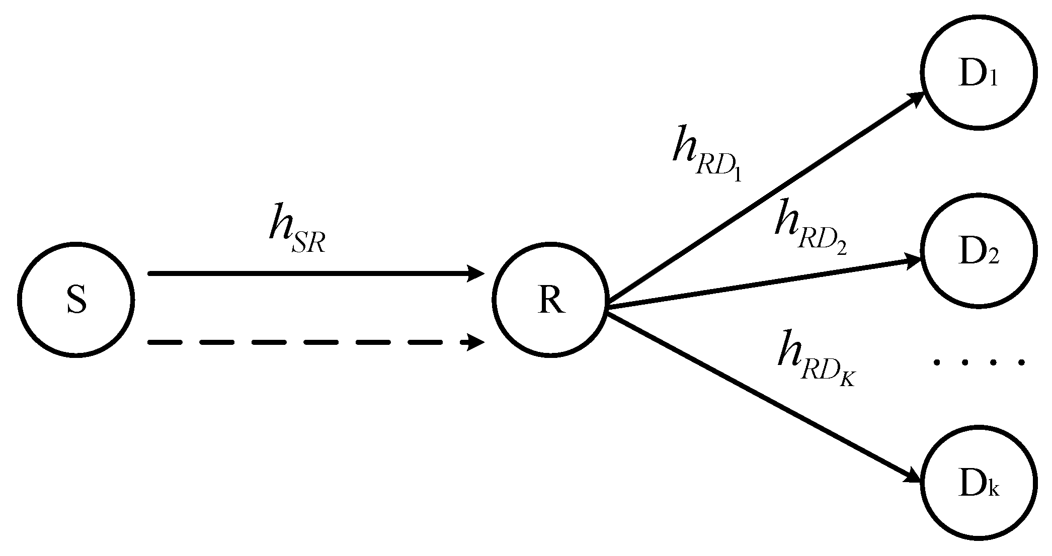
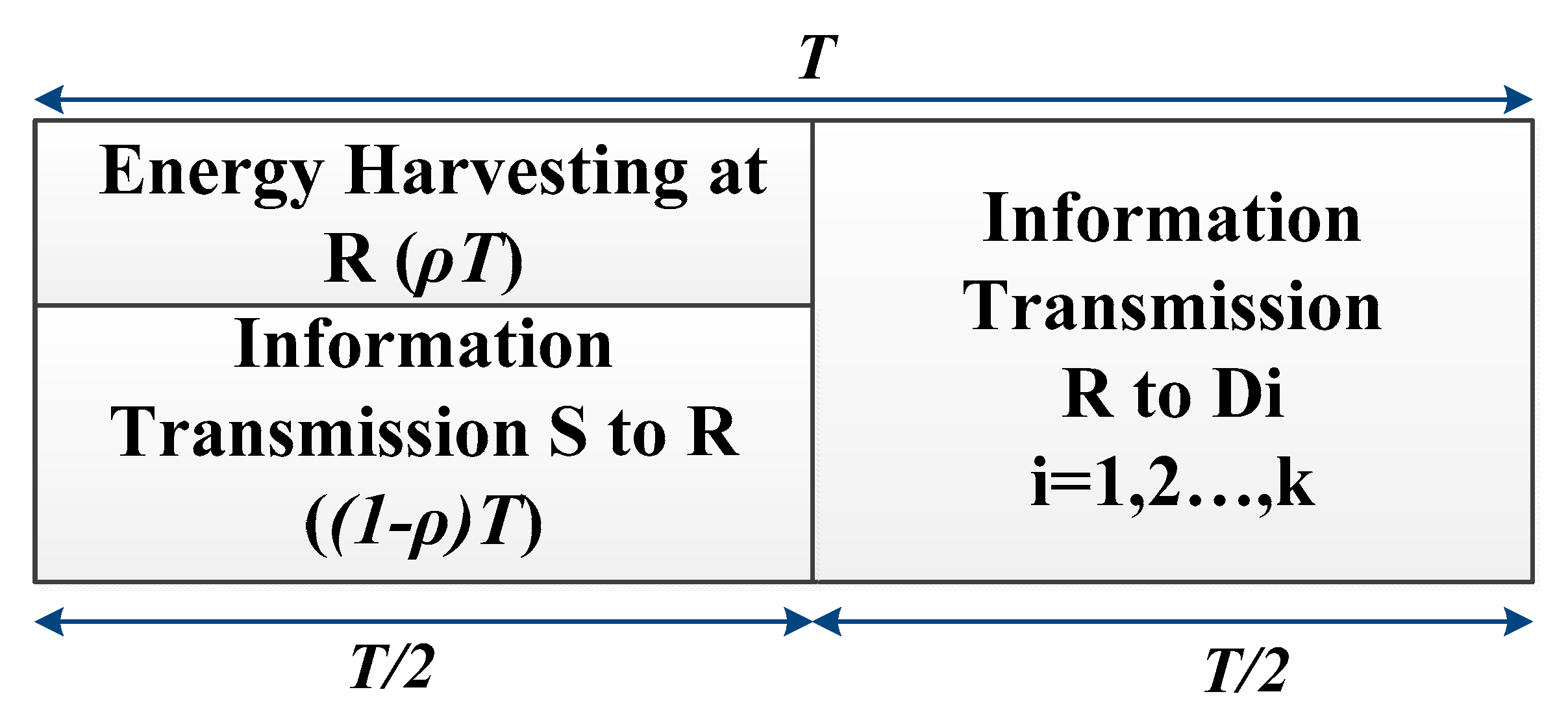
2. System Model
3. The System Performance
3.1. The Outage Probability (OP)
3.2. Maximize Capacity
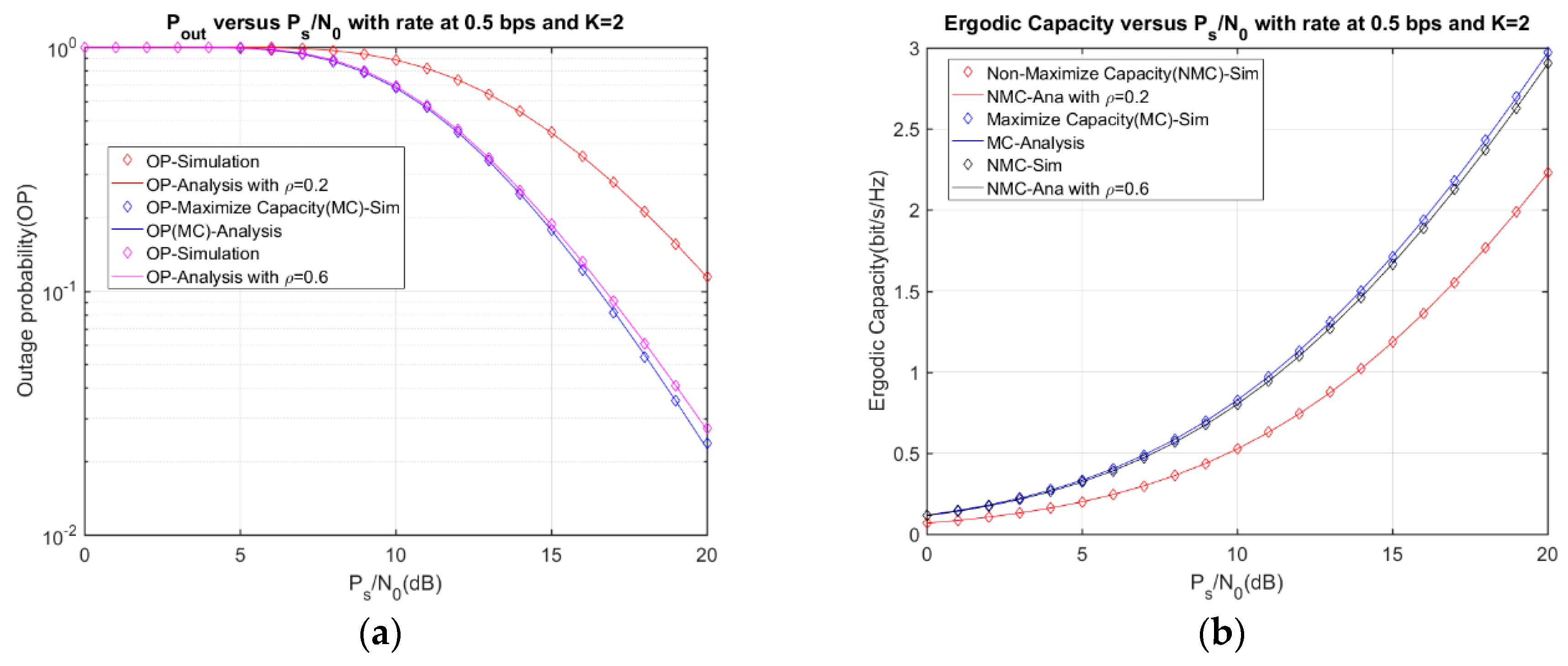
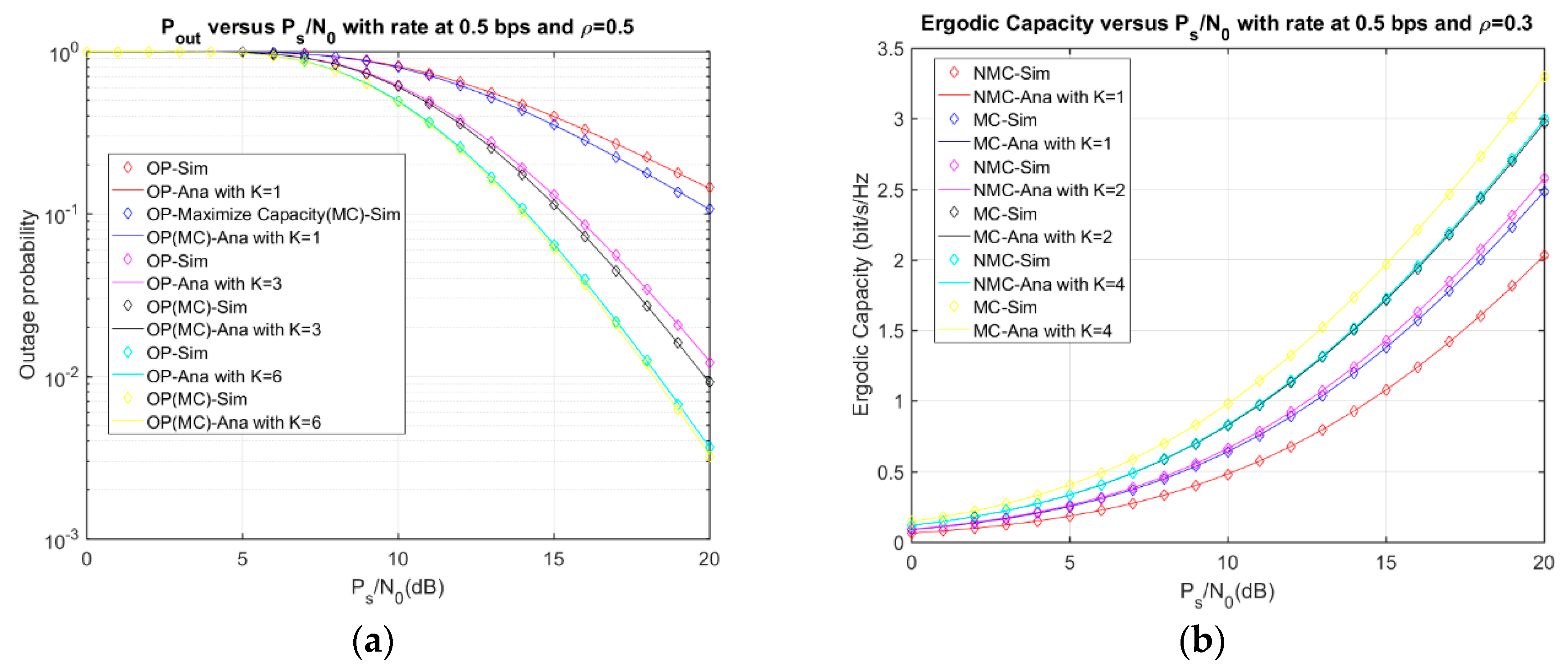
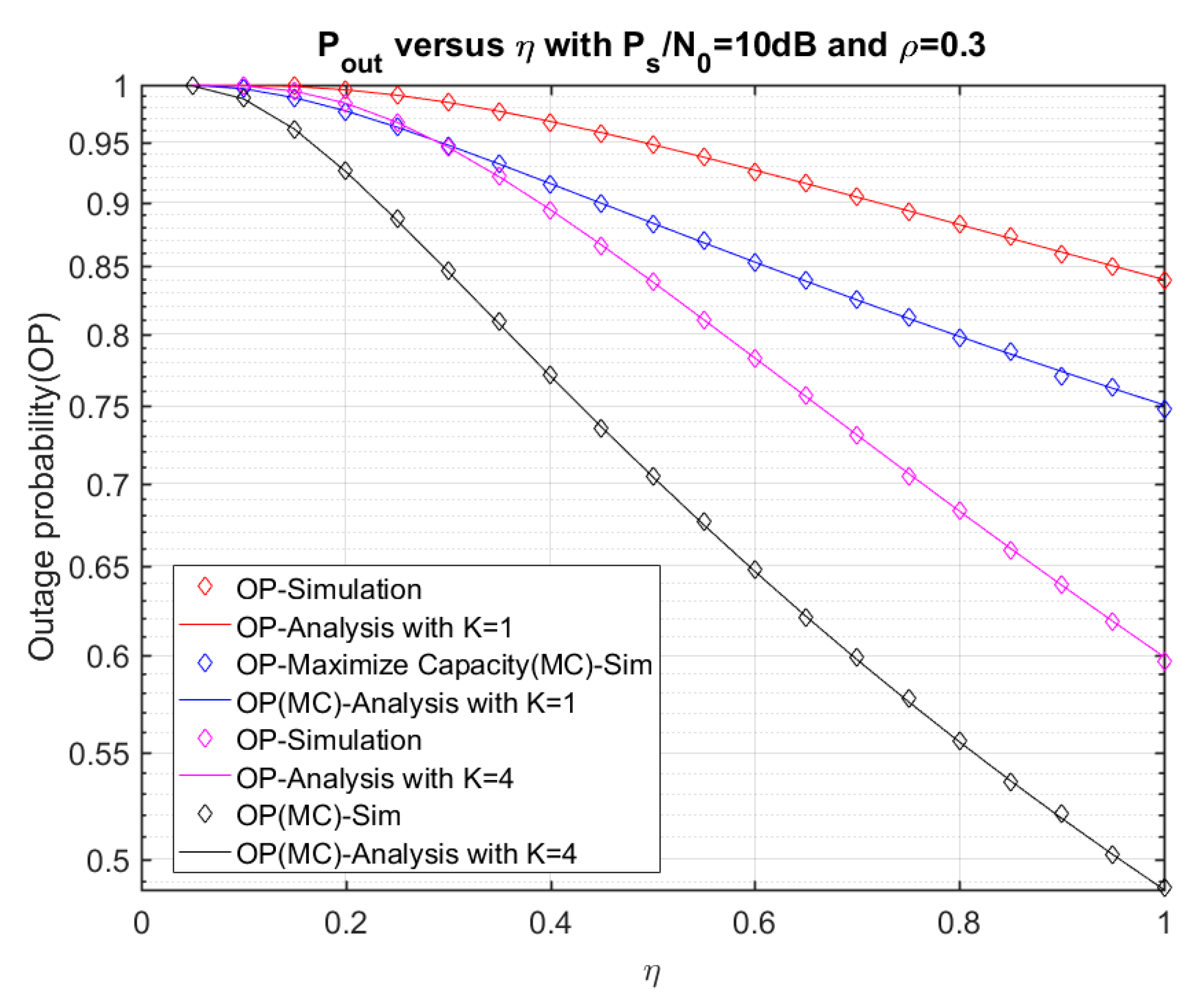
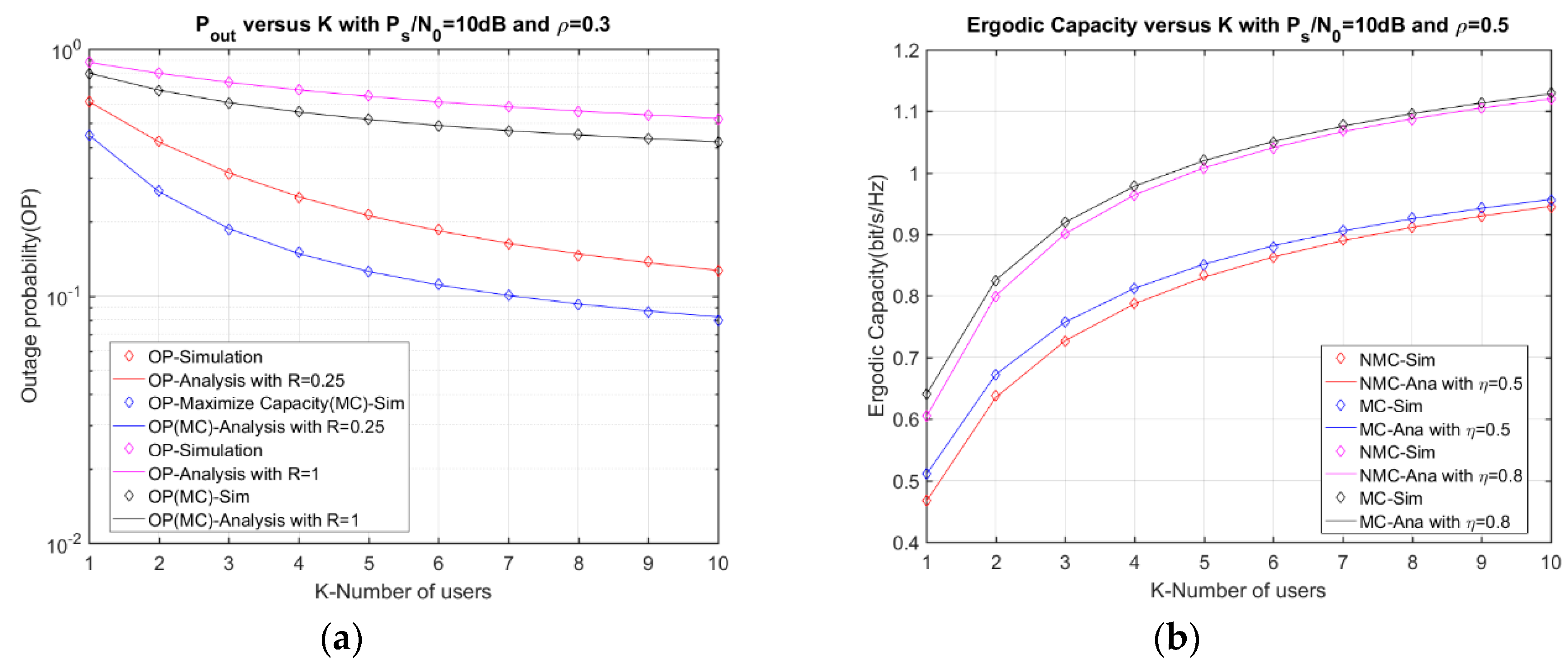
4. Numerical Results and Discussion
5. Conclusions
Author Contributions
Funding
Conflicts of Interest
Appendix A
Appendix B
References
- Bi, S.; Ho, C.K.; Zhang, R. Wireless powered communication: Opportunities and challenges. IEEE Commun. Mag. 2015, 53, 117–125. [Google Scholar] [CrossRef]
- Niyato, D.; Kim, D.I.; Maso, M.; Han, Z. Wireless Powered Communication Networks: Research Directions and Technological Approaches. IEEE Wirel. Commun. 2017, 2–11. [Google Scholar] [CrossRef]
- Yu, H.; Lee, H.; Jeon, H. What is 5G? Emerging 5G Mobile Services and Network Requirements. Sustainability 2017, 9, 1848. [Google Scholar] [CrossRef]
- Zhou, X.; Zhang, R.; Ho, C.K. Wireless Information and Power Transfer: Architecture Design and Rate-Energy Tradeoff. IEEE Trans. Commun. 2013, 61, 4754–4767. [Google Scholar] [CrossRef]
- Lee, S.; Zhang, R.; Huang, K. Opportunistic Wireless Energy Harvesting in Cognitive Radio Networks. IEEE Trans. Commun. 2013, 12, 4788–4799. [Google Scholar] [CrossRef]
- Chen, H.; Zhai, C.; Li, Y.; Vucetic, B. Cooperative Strategies for Wireless-Powered Communications: An Overview. IEEE Wirel. Commun. 2018, 25, 112–119. [Google Scholar] [CrossRef]
- Duy, T.T.; Son, V.N.; Tung, V.T.; Alexandropoulos, G.C.; Duong, T.Q. Outage performance of cognitive cooperative networks with relay selection over double-Rayleigh fading channels. IET Commun. 2016, 10, 57–64. [Google Scholar] [CrossRef]
- Ho-Van, K.; Sofotasios, P.C.; Alexandropoulos, G.C.; Freear, S. Bit error rate of underlay decode-and-forward cognitive networks with best relay selection. J. Commun. Netw. 2015, 17, 162–171. [Google Scholar] [CrossRef]
- Alexandropoulos, G.C.; Papadogiannis, A.; Sofotasios, P.C. A Comparative Study of Relaying Schemes with Decode and Forward over Nakagami-Fading Channels. J. Comput. Netw. Commun. 2011, 2011, 1–14. [Google Scholar] [CrossRef]
- Nguyen, T.; Tran, M.; Nguyen, T.-L.; Ha, D.-H.; Voznak, M. Multisource Power Splitting Energy Harvesting Relaying Network in Half-Duplex System over Block Rayleigh Fading Channel: System Performance Analysis. Electronics 2019, 8, 67. [Google Scholar] [CrossRef]
- Yao, C.-H.; Pei, C.-X.; Guo, J. Performance analysis of two-way AF cooperative networks with relay selection over Nakagami-m fading channels. Inf. Technol. Appl. 2015, 9, 307–311. [Google Scholar]
- Nguyen, T.; Quang Minh, T.; Tran, P.; Vozňák, M. Energy Harvesting over Rician Fading Channel: A Performance Analysis for Half-Duplex Bidirectional Sensor Networks under Hardware Impairments. Sensors 2018, 18, 1781. [Google Scholar] [CrossRef]
- Nguyen, T.N.; Minh, T.H.; Tran, P.T.; Voznak, M. Adaptive Energy Harvesting Relaying Protocol for Two-Way Half Duplex System Network over Rician Fading Channel. Wirel. Commun. Mob. Comput. 2018, 2018, 1–10. [Google Scholar] [CrossRef]
- Nguyen, T.N.; Duy, T.T.; Luu, G.T.; Tran, P.T.; Vozňák, M. Energy Harvesting-based Spectrum Access with Incremental Cooperation, Relay Selection and Hardware Noises. Radioengineering 2017, 26, 240–250. [Google Scholar] [CrossRef]
- Nguyen, T.N.; Minh, T.H.; Tran, P.T.; Voznak, M.; Duy, T.T.; Nguyen, T.L.; Tin, P.T. Performance Enhancement for Energy Harvesting Based Two-way Relay Protocols in Wireless Ad-hoc Networks with Partial and Full Relay Selection Methods. Ad Hoc Netw. 2019, 84, 178–187. [Google Scholar] [CrossRef]
- Gündüz, D.; Devillers, B. Two-hop Communication with Energy Harvesting. In Proceedings of the 2011 4th IEEE International Workshop on Computational Advances in Multi-Sensor Adaptive Processing (CAMSAP), San Juan, Puerto Rico, 13–16 December 2011. [Google Scholar] [CrossRef]
- Chen, H.; Li, Y.; Rebelatto, J.L.; Uchoa-Filho, B.F.; Vucetic, B. Harvest-Then-Cooperate: Wireless-Powered Cooperative Communications. IEEE Trans. Signal Process. 2015, 63, 1700–1711. [Google Scholar] [CrossRef]
- Xiong, K.; Fan, P.; Zhang, C.; Letaief, K.B. Wireless Information and Energy Transfer for Two-Hop Non-Regenerative MIMO-OFDM Relay Networks. IEEE J. Sel. Areas Commun. 2015, 33, 1595–1611. [Google Scholar] [CrossRef]
- Okandeji, A.A.; Khandaker, M.R.; Wong, K.K. Two-way Beamforming Optimization for Full-duplex SWIPT Systems. In Proceedings of the 2016 24th European Signal Processing Conference (EUSIPCO), Budapest, Hungary, 29 August–2 September 2016. [Google Scholar] [CrossRef]
- Okandeji, A.A.; Khandaker, M.R.; Wong, K.K.; Zheng, Z. Joint Transmit Power and Relay Two-Way Beamforming Optimization for Energy-Harvesting Full-Duplex Communications. In Proceedings of the 2016 IEEE Globecom Workshops (GC Wkshps), Washington, DC, USA, 4–8 December 2016. [Google Scholar] [CrossRef]
- Hu, Y.; Zhu, Y.; Schmeink, A. Simultaneous Wireless Information and Power Transfer in Relay Networks with Finite Blocklength Codes. In Proceedings of the 2017 23rd Asia-Pacific Conference on Communications (APCC), Perth, Australia, 11–13 December 2017. [Google Scholar] [CrossRef]
- Halima, N.B.; Boujemaa, H. Exact and Approximate Symbol Error Probability of cooperative systems with best relay selection and all participating relaying using Amplify and Forward or Decode and Forward Relaying over Nakagami-m fading channels. KSII Trans. Internet Inf. Syst. 2018, 12, 81–108. [Google Scholar]
- Tseng, S.-M.; Lee, T.-L.; Ho, Y.-C.; Tseng, D.-F. Distributed space-time block codes with embedded adaptive AAF/DAF elements and opportunistic listening for multihop power line communication networks. Int. J. Commun. Syst. 2015, 30, e2950. [Google Scholar] [CrossRef]
- Li, Y.; Vucetic, B. On the Performance of a Simple Adaptive Relaying Protocol for Wireless Relay Networks. In Proceedings of the VTC Spring 2008—IEEE Vehicular Technology Conference, Singapore, 11–14 May 2008. [Google Scholar]
- Tseng, S.-M.; Liao, C.-Y. Distributed Orthogonal and Quasi-Orthogonal Space-Time Block Code with Embedded AAF/DAF Matrix Elements in Wireless Relay Networks with Four Relays. Wirel. Pers. Commun. 2013, 75, 1187–1198. [Google Scholar] [CrossRef]
- Katti, S.; Gollakota, S.; Katabi, D. Embracing Wireless Interference. ACM SIGCOMM Comput. Commun. Rev. 2007, 37, 397–408. [Google Scholar] [CrossRef]
- Qin, J.; Zhu, Y.; Zhe, P. Broadband Analog Network Coding With Robust Processing for Two-Way Relay Networks. IEEE Commun. Lett. 2017, 21, 1115–1118. [Google Scholar] [CrossRef]
- Nasir, A.A.; Zhou, X.; Durrani, S.; Kennedy, R.A. Relaying Protocols for Wireless Energy Harvesting and Information Processing. IEEE Trans. Commun. 2013, 12, 3622–3636. [Google Scholar] [CrossRef]
- Deng, Y.; Wang, L.; Elkashlan, M.; Kim, K.J.; Duong, T.Q. Generalized Selection Combining for Cognitive Relay Networks Over Nakagami-m Fading. IEEE Trans. Signal Process. 2015, 63, 1993–2006. [Google Scholar] [CrossRef]
- Nguyen, T.N.; Tran, P.T.; Minh, T.H.Q.; Voznak, M.; Sevcik, L. Two-Way Half Duplex Decode and Forward Relaying Network with Hardware Impairment over Rician Fading Channel: System Performance Analysis. Electron. Electr. Eng. 2018, 24, 74–78. [Google Scholar] [CrossRef]
- Owen, D.B.; Abramowitz, M.; Stegun, I.A. Handbook of Mathematical Functions with Formulas, Graphs, and Mathematical Tables. Technometrics 1965, 7, 78. [Google Scholar] [CrossRef]
- Gradshteyn, I.S.; Ryzhik, I.M. Table of Integrals, Series, and Products, 8th ed.; Daniel, Z., Victor, M., Eds.; Academic Press: Amsterdam, The Netherlands, 2015. [Google Scholar]
- Bhatnagar, M.R. On the Capacity of Decode-and-Forward Relaying over Rician Fading Channels. IEEE Commun. Lett. 2013, 17, 1100–1103. [Google Scholar] [CrossRef]
- Mouapi, A.; Hakem, N. A New Approach to Design Autonomous Wireless Sensor Node Based on RF Energy Harvesting System. Sensors 2018, 18, 133. [Google Scholar] [CrossRef]
- Wang, C.; Li, J.; Yang, Y.; Ye, F. Combining Solar Energy Harvesting with Wireless Charging for Hybrid Wireless Sensor Networks. IEEE Trans. Mob. Comput. 2018, 17, 560–576. [Google Scholar] [CrossRef]
- Chu, Z.; Zhou, F.; Zhu, Z.; Hu, R.Q.; Xiao, P. Wireless Powered Sensor Networks for Internet of Things: Maximum Throughput and Optimal Power Allocation. IEEE Internet Things J. 2018, 5, 310–321. [Google Scholar] [CrossRef]


| Symbol | Name | Values |
|---|---|---|
| Energy harvesting efficiency | 0.8 | |
| Mean of | 0.5 | |
| Mean of | 0.5 | |
| Nakagami m-factor | 3 | |
| z | SNR threshold | 1 |
| Ps/N0 | Source power to noise ratio | 0–20 dB |
| R | Source rate | 0.5 bit/s/Hz |
| K | Number of users | 1–6 |
| m | Pathloss exponent | 3 |
| dsr = di | the distance of S-R link and R-D link, respectively | 0.85 |
© 2019 by the authors. Licensee MDPI, Basel, Switzerland. This article is an open access article distributed under the terms and conditions of the Creative Commons Attribution (CC BY) license (http://creativecommons.org/licenses/by/4.0/).
Share and Cite
Nguyen, T.N.; Tran, M.; Nguyen, T.-L.; Ha, D.-H.; Voznak, M. Performance Analysis of a User Selection Protocol in Cooperative Networks with Power Splitting Protocol-Based Energy Harvesting Over Nakagami-m/Rayleigh Channels. Electronics 2019, 8, 448. https://doi.org/10.3390/electronics8040448
Nguyen TN, Tran M, Nguyen T-L, Ha D-H, Voznak M. Performance Analysis of a User Selection Protocol in Cooperative Networks with Power Splitting Protocol-Based Energy Harvesting Over Nakagami-m/Rayleigh Channels. Electronics. 2019; 8(4):448. https://doi.org/10.3390/electronics8040448
Chicago/Turabian StyleNguyen, Tan N., Minh Tran, Thanh-Long Nguyen, Duy-Hung Ha, and Miroslav Voznak. 2019. "Performance Analysis of a User Selection Protocol in Cooperative Networks with Power Splitting Protocol-Based Energy Harvesting Over Nakagami-m/Rayleigh Channels" Electronics 8, no. 4: 448. https://doi.org/10.3390/electronics8040448
APA StyleNguyen, T. N., Tran, M., Nguyen, T.-L., Ha, D.-H., & Voznak, M. (2019). Performance Analysis of a User Selection Protocol in Cooperative Networks with Power Splitting Protocol-Based Energy Harvesting Over Nakagami-m/Rayleigh Channels. Electronics, 8(4), 448. https://doi.org/10.3390/electronics8040448