Article

Tri-polarized Sparse Array Design for Mutual Coupling Reduction in Direction Finding and Polarization Estimation

School of Information and Electronics, Beijing Institute of Technology, Beijing 100081, China
*
Author to whom correspondence should be addressed.
Electronics 2019, 8(12), 1557; https://doi.org/10.3390/electronics8121557
Submission received: 19 November 2019 / Revised: 9 December 2019 / Accepted: 12 December 2019 / Published: 17 December 2019
(This article belongs to the Special Issue Recent Advances in Array Antenna and Array Signal Processing)

Abstract

:
Multi-polarized antenna arrays have the ability to provide both the direction and polarization information of the incident signals, which is important in radar, sonar, wireless communication, remote sensing, and so on. In this paper, a diversely polarized linear array of sparsely located but identically oriented tri-polarized vector antennas (VAs) is designed for estimating the direction-of-arrival (DOA) and polarization parameters of the incident signals in the presence of antenna mutual coupling (MC). In order to reduce the inter-VA MC, a new type of sparse array geometry is proposed, wherein the minimum inter-VA spacing is constrained to be no less than one signal wavelength. Considering the intra-VA MC effect, a full-wave electromagnetic simulation is introduced to fit the manifold vector of an isolated VA. Based on the sparse VA array, a polarimetric subspace scheme is proposed for DOA and polarization estimation. When the knowledge about the intra-VA MC is a priori unavailable, an algebraic polarimetric blind scheme is also provided for DOA estimation. Computer simulations and real-world experiments (using an S-band 24-channel tri-polarized array system) validate the efficacy of the designed array geometry along with the parameter estimation methods.

1. Introduction

Multi-polarized vector antenna (VA) arrays can be used to fulfill polarization–time–space joint signal processing. The exploitation of the polarization difference of signals is potentially helpful for enhanced parameter estimation or beamforming [1,2,3]. A variety of approaches to parameter estimation with different types of VAs have been proposed in the literature; see, for instance, the work in [4,5,6,7,8,9,10,11,12,13]. The design of multi-polarized VAs is also of interest for practical real-world parameter estimation, such as the work reported in [14,15,16,17,18,19,20].
A VA represents an antenna group which generally consists of several co-centered but diversely polarized dipoles/loops. An important problem in VA array signal parameter estimation is the alleviation of the intra-VA and inter-VA mutual coupling (MC) effects. For intra-VA MC reduction, one of the current measures is to develop a “distributed” (“stretched”) VA whose constituent dipoles/loops are not spatially co-centered [10,16,17,18]. Note that the approximate characteristics of an isolated VA (either co-located or distributed) involving MC can be also calculated via method of moments (MoM)-based full-wave electromagnetic simulations [21,22,23].
For inter-VA MC reduction, one possible strategy, in addition to array calibration, is to utilize sparsely located VAs. The array geometry may be minimum redundancy (MRA) [24], coprime [25], nested [26], super nested [27], or CADiS (coprime array with displaced subarrays) [28]. The minimum inter-VA spacing of the former four array geometries is half the signal wavelength. The MC between the corresponding VA pairs may not be neglected [21,29]. For CADiS, the inter-VA spacings are larger than half the signal wavelength. This is beneficial for alleviating inter-VA MC. However, the achievable consecutive coarray sensor number, and, thus, the resolvability of CADiS, is reduced compared with the other mentioned sparse arrays. There is still room to improve the design of sparse arrays.
In this paper, a new type of tri-polarized VA sparse array is designed, and two parameter estimation schemes are proposed. In the sparse array, the minimum inter-VA spacing is constrained to be no less than one signal wavelength so that the inter-VA MC can be neglected. Moreover, the aperture extension capability of the newly designed array is higher than that of CADiS. Considering the intra-VA MC, we utilize full-wave electromagnetic simulation to fit the manifold vectors of an isolated VA, based on which a polarimetric subspace scheme is proposed to estimate the direction and polarization parameters. For when the isolated VA manifold vectors are unavailable, a polarimetric blind scheme is presented for direction finding only, where the spatial diversity of the array is effectively used. The designed VA array geometry and the parameter estimation methods are validated by simulated data and real-world data obtained from a newly developed tri-polarized VA array system.
Throughout the paper, superscripts “T”, “*”, and “H” represent the transpose, complex conjugate, and Hermitian transpose, respectively; j = 1 is the imaginary unit; “ ” denotes the Kronecker product; “ E { } ” is the expectation operator; “ | S | ” denotes the cardinality of set S ; and “ S 1 \ S 2 ”, termed as the set difference of S 1 and S 2 , represents the set of elements in S 1 but not in S 2 .

2. Tri-polarized Antenna Array Signal Model

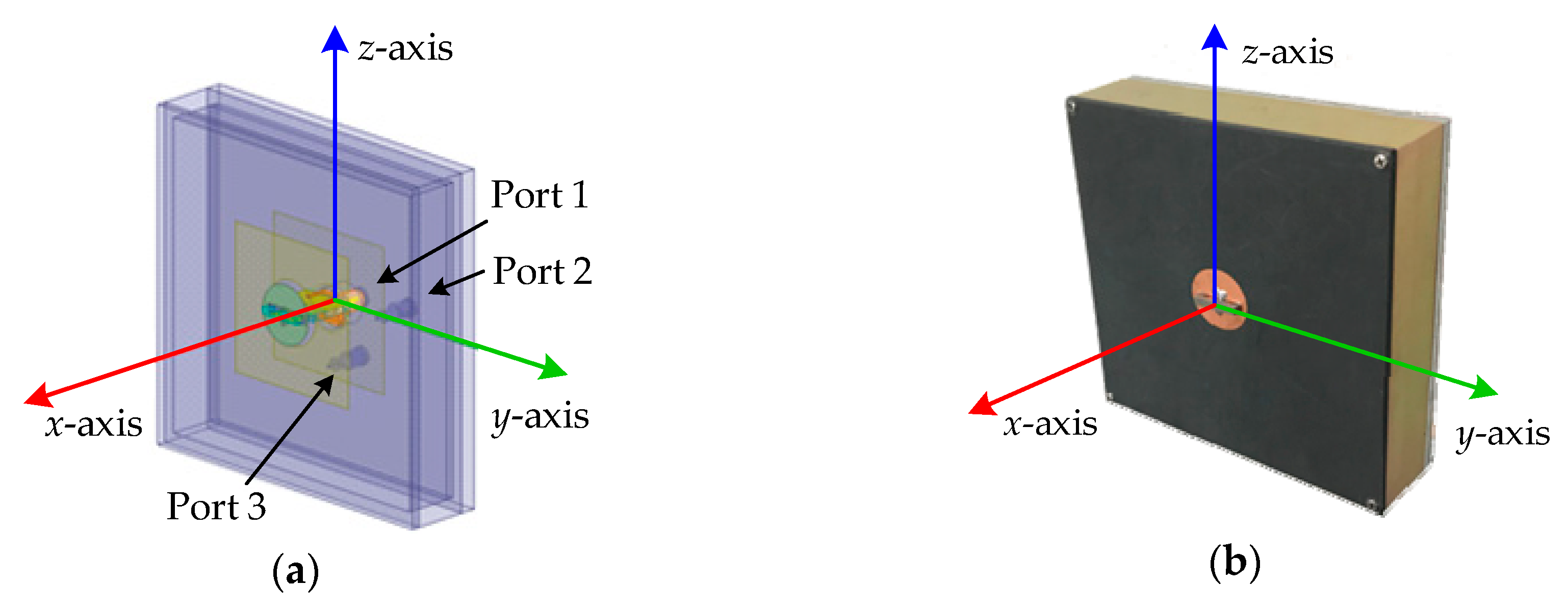
Consider K uncorrelated far-field narrowband signals { s k ( t ) } k = 1 K received by a linear array consisting of N tri-polarized VAs along the y-axis. The direction-of-arrival (DOA) of the kth signal is ( θ k , φ k ) with θ k and φ k denoting the azimuth and elevation angles, respectively, as shown in Figure 1. The VA location set is S = { d 1 , d 2 , d N } (in half signal wavelength). The output of the array can be modeled as a 3 N × 1 vector:
x ( t ) = k = 1 K a ( θ k , φ k , γ k , η k ) s k ( t ) + n ( t )
where a ( θ k , φ k , γ k , η k ) = [ a h ( θ k , φ k ) , a v ( θ k , φ k ) ] h ( γ k , η k ) is the steering vector of the kth signal, with a h ( θ k , φ k ) and a v ( θ k , φ k ) respectively characterizing the array responses to the horizontal and vertical polarimetric components of the kth signal, while h ( γ k , η k ) = [ cos γ k , sin γ k e j η k ] T represents the polarization vector of the kth signal. Here, γ k [ 0 , π / 2 ] and η k ( π , π ] respectively denote the auxiliary polarization angle and the polarization phase difference of the kth signal. n ( t ) is the noise vector, which is assumed to be independent of the signals of interest.
If the inter-VA MC can be ignored (for example, if the minimum inter-VA spacing is no less than one signal wavelength), x ( t ) can be rewritten as
x ( t ) = k = 1 K a iso ( θ k , φ k , γ k , η k ) a s ( θ k , φ k ) s k ( t ) + n ( t )
where a s ( θ k , φ k ) is the N × 1 spatial steering vector of the kth signal:
a s ( θ k , φ k ) = [ e j π d 1 sin θ k sin φ k , e j π d 2 sin θ k sin φ k , e j π d N sin θ k sin φ k ] T .
a iso ( θ k , φ k , γ k , η k ) is the 3 × 1 isolated VA steering vector:
a iso ( θ k , φ k , γ k , η k ) = [ a iso , h ( θ k , φ k ) , a iso , v ( θ k , φ k ) ] h ( γ k , η k )
in which a iso , h ( θ k , φ k ) and a iso , v ( θ k , φ k ) respectively characterize the isolated VA responses to the horizontal and vertical polarimetric components of the kth signal. For a tripole VA, whose constituent antennas are three co-centered, orthogonally oriented short dipoles, a iso , h ( θ k , φ k ) and a iso , v ( θ k , φ k ) are given by a iso , h ( θ k , φ k ) = [ sin θ k , cos θ k , 0 ] T and a iso , v ( θ k , φ k ) = [ cos φ k cos θ k , cos φ k sin θ k , sin φ k ] T [1]. However, for the reasons of unknown anomalies in antenna design and inevitable intra-VA MC, closed-form expressions of a iso , h ( θ , φ ) and a iso , v ( θ , φ ) (also known as the horizontal and vertical isolated VA manifold vectors) are generally unavailable.
In practice, full-wave electromagnetic simulations can be used to determine the parametric models of a iso , h ( θ , φ ) and a iso , v ( θ , φ ) from the gain and phase patterns of horizontal and vertical polarizations [21,22,23]. Figure 2 shows the topology and prototype of a tri-polarized antenna used in the S-band 24-channel array system. This antenna consists of two orthogonally polarized microstrips (y- and z-directions) and a collocated monopole (x-direction), with physical size larger than a half-wavelength. The gain patterns of horizontal and vertical polarizations for this tri-polarized antenna are shown in Figure 3.

3. Inter-VA Spacing-Constrained Sparse Array

In this section, an inter-VA spacing-constrained (ISC) array geometry is designed to reduce the inter-VA MC.
Recall that the VA location set of the physical array is S = { d 1 , d 2 , d N } ; the second-order difference coarray is
D = { d m , n = d m d n | m , n = 1 , , N ; m n } .
Here, we set d 1 = 0 . In what follows, we show that a virtual uniform linear array (ULA) V D of no less than 2 ( N 1 ) 2 virtual VAs can be synthesized via a proper design of S . The inter-VA spacing of the virtual ULA is of half the signal wavelength. If N > 4 , more degrees of freedom (DOFs) can be achieved for estimating the DOAs of signals. The processing aperture of the virtual ULA of VAs is also larger than that of a physical ULA of N VAs located at { 0 , 1 , 2 , , N 1 } given that N > 4 .
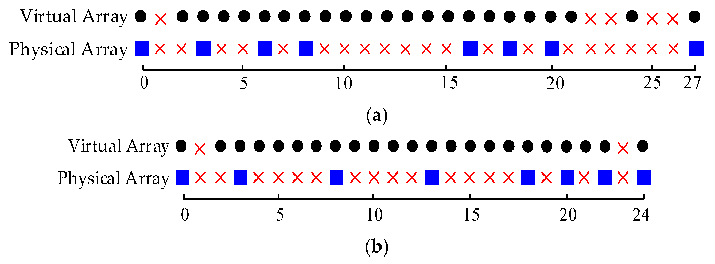
If the minimum inter-VA spacing of the physical array is constrained to be no less than one signal wavelength, then d m , n 1 and d m , n d N 1 ; therefore, there will be at least two “gaps” at the positions 1 and d N 1 in D (see, for example, the ISC arrays and their virtual counterparts as shown in Figure 4).
The attempt here is to find a virtual ULA with as many as possible virtual VAs located at 2, 3, 4, 5, etc. (see also Figure 4 for the mentioned virtual ULA: the consecutive subarray of the virtual array). More precisely, given N and the array aperture L , the VA locations { d n } n = 1 N of the ISC array can be designed according to the following criterion:
max d n S N 0 s . t . V = { 2 , 3 , , N 0 } D , d m , n 2 , 1 n < m N d 0 = 0 , d N = L .
Additionally, in order to achieve a higher DOF than that of the physical array, it is desired that the aperture of the virtual ULA N V = N 0 1 be much larger than N . If N is small, the ISC array configurations satisfying criterion (6) can be found by exhaustive search through all the possible combinations of VA locations, or by using the computationally more efficient Scrunch recursive algorithm based on [30], which is summarized in Algorithm 1. If N is large, numerical algorithms such as simulated annealing [31] and ant colony optimization [32] can be used to find the suboptimal solution to (6).
Algorithm 1 Scrunch recursive algorithm for an ISC array
Input: the number of VAs N
    the array aperture L
Output: the ISC array configuration S
    the position of the rightmost VA in the consecutive virtual array N 0
Procedure:
  • Set two VAs at the endpoints of the ISC array, i.e., d 1 = 0 , d N = L and S = { 0 , L } , with the number of remaining VAs N r = N 2 . Define two markers M L and M R ( 2 M L < M R L 2 ) which indicate the positions the VAs attempted to set in the scrunching procedure from the ends of the array towards the center.
  • Initialize N 0 with N 0 = L 2 and proceed to steps 3–23. If no S is found, decrease N 0 and repeat the same steps until at least one S is found, then return S and N 0 .
  • Denote the uncovered section of the consecutive virtual array { 2 , , N 0 } in the scrunching procedure by V u = { p L , p L + 1 , , p R } , and initialize it with p L = 2 and p R = N 0 . The number of positions in the uncovered section N u is then initialized to N u = N 0 1 .
  • Repeat the following recursive function Scrunch ( N r , M L , M R , V u , S ) in steps 5–23.
  • Calculate N u = | V u | and N m = N r ( N r 1 ) / 2 + N r ( N N r ) which represents the maximum possible lags that can be generated by the N r VAs.
  • if N u > 0 , then
  • if N u > N m , then
  • Return null.
  • else
  • while N r < M R M L
  • Determine the amount of scrunch Δ d : if M L S or M R S , Δ d = 2 ; else Δ d = 1 .
  • if M L + M R L , then
  • Try to add a VA at position p t = M L + Δ d . Update M L by M L M L + Δ d .
  • else
  • Try to add a VA at position p t = M R Δ d . Update M R by M R M R Δ d .
  • end if
  • Calculate the difference coarray D of the set S { p t } by using (5).
  • Call Scrunch ( N r 1 , M L , M R , V u \ D , S { p t } ) recursively.
  • end while
  • end if
  • else
  • Return S , which satisfies the ISC criterion (6).
  • end if
Listed in Table 1 are some 8-VA ISC array geometries under different specifications of L and N 0 (for a certain value of L , the ISC array geometry may be nonunique; the mirror image is omitted for brevity). Analogous to [33], letting and G be the numbers of redundant lags and gaps in D associated with the subaperture of the virtual array between 2 and d N 2 , respectively, we have the following remarks:
  • Given N , the aperture parameter L is important for the design of the ISC array ( L 2 ( N 1 ) + 1 is required). If N 3 , there exists a certain set of aperture parameters achieving N 0 = L 2 (i.e., G = 0 ). The obtained “fully augmentable” ISC arrays involve different redundancies. Concerning aperture extension, the ISC array with “minimum redundancy” (where is minimal or even zero) is of interest. For example, if N = 8 , the use of any L belonging to the set { 15 , 16 , , 25 } will lead to a fully augmentable ISC array. The ISC array with L = 25 is of minimal redundancy and the virtual aperture N V is larger than others. For different values of N , some minimum-redundancy ISC array configurations are listed in Table A1 of Appendix A.
  • For the same setting of N , the virtual aperture of the ISC array can be further increased by using a larger L . The obtained ISC arrays now are “partially augmentable” ( G 0 ). A partially augmentable ISC array is said to be “maximum contiguous” if the synthesized virtual ULA has the largest aperture. For example, if N = 8 , N 0 = 24 ( N V = 23 ) for the maximum-contiguous ISC array ( L = 31 ), while N 0 = 23 ( N V = 22 ) for the minimum-redundancy ISC array ( L = 25 ).
  • A degenerate case is N = 3 , under which N V = 2 < 3 . Note also that N V = 4 when N = 4 . So, if aperture extension and mutual coupling reduction are desired, N should be no less than 4.

4. ISC-Based DOA–Polarization Parameter Estimation

In this section, two subspace approaches to signal parameter estimation are presented by using the ISC array of tri-polarized VAs designed in Section 3.
Consider first the covariance matrix of the array output vector x ( t ) , which is defined as R = E { x ( t ) x H ( t ) } . Under the assumptions made in the paper, for the ISC array, it can be verified that
R = k = 1 K σ k 2 ( a iso , k a s , k ) ( a iso , k a s , k ) H + σ 2 I
where a iso , k = a iso ( θ k , φ k , γ k , η k ) , a s , k = a s ( θ k , φ k ) , σ k 2 is the power of the kth signal, and σ 2 is the power of noise. In practice, R is replaced by its sample estimate R ^ , while σ 2 is estimated by averaging the smaller eigenvalues of R ^ . By using the properties of the Kronecker product, ( a b ) H = a H b H and ( a b ) ( c H d H ) = ( a c H ) ( b d H ) , we have
R ¯ = R σ 2 I = k = 1 K σ k 2 ( a iso , k a iso , k H ) ( a s , k a s , k H ) .
We then partition the 3 N × 3 N matrix R ¯ as follows:
R ¯ = [ R 11 R 12 R 13 R 21 R 22 R 23 R 31 R 32 R 33 ]
in which R u v ( u , v = 1 , 2 , 3 ) is the N × N sub-matrix given by
R u v = k = 1 K σ k 2 r k u v a s , k a s , k H
where r k u v = a iso , k ( u ) a iso , k ( v ) . Vectorizing R u v yields further the following coarray model:
r u v = k = 1 K σ k 2 r k u v ( a s , k a s , k ) .
Following [24], an N V × N 2 selection matrix J (depending on S ) can be constructed to synthesize the aforementioned virtual ULA of VAs associated with V , i.e., z V u v = J r u v . We then divide the virtual ULA z V u v into N z = N V / 2 overlapping subarrays of size N z , where “ x ” signifies the smallest integer not less than x . Letting the position of the N z th VA be the phase reference point, the nth subarray data can be written as
z n u v = k = 1 K σ k 2 r k u v ρ k n 1 v ( θ k , φ k )
where ρ k n 1 = exp { j π ( n 1 ) sin θ k sin φ k } and
v ( θ k , φ k ) = [ 1 , e j π d sin θ k sin φ k , , e j π ( N z 1 ) sin θ k sin φ k ] T .
It follows that
R V u v = [ z 1 u v , z 2 u v , , z N z u v ] = k = 1 K σ k 2 r k u v v ( θ k , φ k ) v H ( θ k , φ k ) .
To fulfill DOA and polarization joint estimation, let us consider now the following polarimetric covariance matrix of the virtual ULA of VAs:
R V = [ R V 11 R V 12 R V 13 R V 21 R V 22 R V 23 R V 31 R V 32 R V 33 ] = k = 1 K σ k 2 b θ k , φ k , γ k , η k b θ k , φ k , γ k , η k H
where
b θ k , φ k , γ k , η k = [ a iso , h ( θ k , φ k ) v ( θ k , φ k ) , a iso , v ( θ k , φ k ) v ( θ k , φ k ) ] H ( θ k , φ k ) h ( γ k , η k )
is the virtual steering vector of the kth signal.
Let U be the 3 N z × ( 3 N z K ) orthonormal matrix whose columns are the eigenvectors of R V associated with its 3 N z K smallest (zero) eigenvalues. With U , DOA and polarization estimation then can be accomplished based on the rank deficient rationale, by applying, e.g., the two optional schemes presented below.

4.1. Using the Nominal Isolated VA Manifold Vectors

Let a ^ iso , h ( θ , φ ) and a ^ iso , v ( θ , φ ) be the nominal horizontal and vertical isolated VA manifold vectors obtained via full-wave electromagnetic simulations; following [4], the DOA and polarization parameters can be obtained by solving the following optimization problem:
{ θ k , φ k , γ k , η k } = arg min θ , φ , γ , η ( b ^ ( θ , φ , γ , η ) | | b ^ ( θ , φ , γ , η ) | | ) H U U H ( b ^ ( θ , φ , γ , η ) | | b ^ ( θ , φ , γ , η ) | | ) = arg min θ , φ , γ , η h H ( γ , η ) D 1 ( θ , φ ) h ( γ , η ) h H ( γ , η ) H 1 H ( θ , φ ) H 1 ( θ , φ ) h ( γ , η ) , k = 1 , , K
where
b ^ ( θ , φ , γ , η ) = [ a ^ iso , h ( θ , φ ) v ( θ , φ ) , a ^ iso , v ( θ , φ ) v ( θ , φ ) ] h ( γ , η ) ,
H 1 ( θ , φ ) = [ a ^ iso , h ( θ , φ ) v ( θ , φ ) , a ^ iso , v ( θ , φ ) v ( θ , φ ) ] ,
D 1 ( θ , φ ) = H 1 H ( θ , φ ) U U H H 1 ( θ , φ ) .
The object function belongs to the standard generalized Rayleigh quotient, and the DOA parameters and polarization parameters can be estimated separately. To be specific, the DOA parameter can be found from the peaks of the following spatial spectrum:
S 1 ( θ , φ ) = λ min 1 { D 1 ( θ , φ ) , H 1 H ( θ , φ ) H 1 ( θ , φ ) }
where “ λ min { A , B } ” denotes the minimal generalized eigenvalue of matrix pencil { A , B } .
Let h ^ k be the corresponding generalized eigenvector of { D 1 ( θ ^ k , φ ^ k ) , H 1 H ( θ ^ k , φ ^ k ) H 1 ( θ ^ k , φ ^ k ) } , with θ ^ k and φ ^ k denoting the estimates of θ k and φ k , respectively; the polarization parameters of the kth signal can then be estimated as γ ^ k = arctan { | h ^ k ( 2 ) / h ^ k ( 1 ) | } and η ^ k = { h ^ k ( 2 ) / h ^ k ( 1 ) } . We call this method the type-1 polarimetric subspace scheme (PS1).

4.2. Without Using the Nominal Isolated VA Manifold Vectors

If the polarization states of the signals are not of interest, or no knowledge about the isolated VA manifold vectors (or intra-VA MC) is available, an optional polarimetric blind scheme can be used to fulfill DOA estimation. Note that
b ( θ , φ , γ , η ) = [ I 3 v ( θ , φ ) ] [ a iso , h ( θ , φ ) , a iso , v ( θ , φ ) ] h ( γ , η ) a iso ( θ , φ , γ , η ) .
Analogous to (17), DOA parameters can be estimated by solving the following optimization problem:
{ θ k , φ k } = arg min θ , φ a iso H ( θ , φ , γ , η ) D 2 ( θ , φ ) a iso ( θ , φ , γ , η ) a iso H ( θ , φ , γ , η ) H 2 H ( θ , φ ) H 2 ( θ , φ ) a iso ( θ , φ , γ , η ) , k = 1 , , K
Here,
H 2 ( θ , φ ) = I 3 v ( θ , φ ) ,
D 2 ( θ , φ ) = H 2 H ( θ , φ ) U U H H 2 ( θ , φ ) .
Since the VA manifold vectors are not available, we put the 3 × 1 vector a iso ( θ , φ , γ , η ) aside and only estimate the DOA parameters from the minimization of the generalized Rayleigh quotient. Similar to (21), we redefine the spatial spectrum as follows:
S 2 ( θ , φ ) = λ min 1 { D 2 ( θ , φ ) , H 2 H ( θ , φ ) H 2 ( θ , φ ) } .
The DOA parameters can be found from the peaks. We call this method the type-2 polarimetric subspace scheme (PS2).
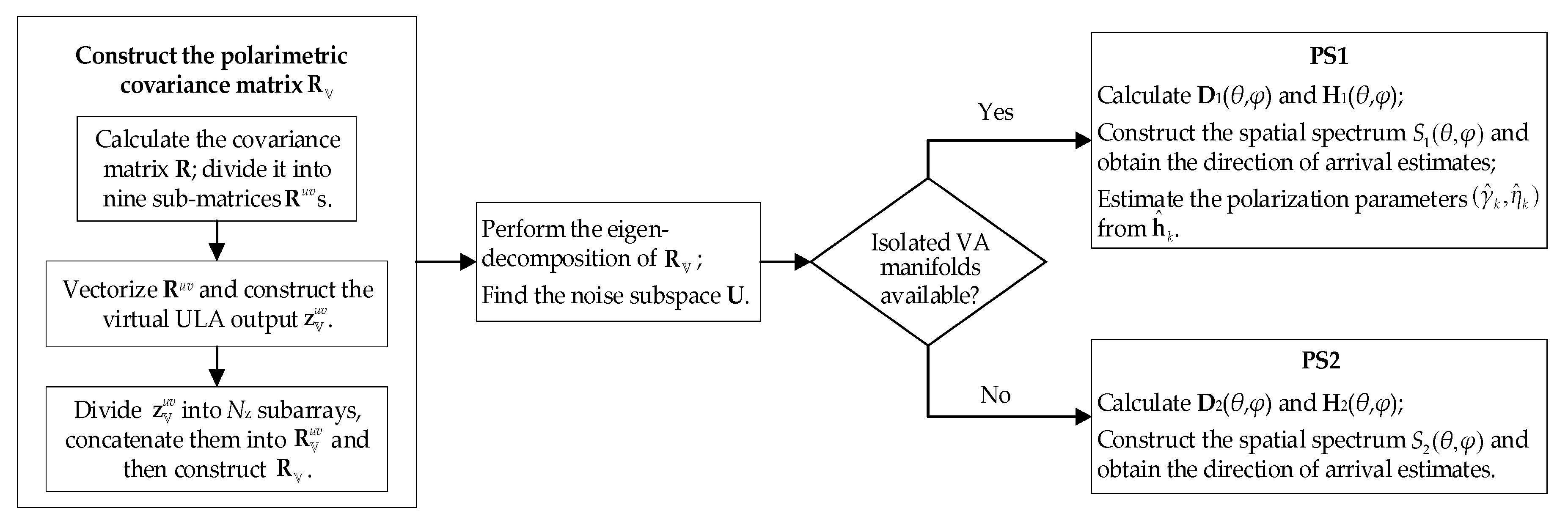
A flow chart of the key steps of PS1 and PS2 is illustrated in Figure 5.

4.3. Analysis of Intra-VA MC Alleviation in PS1 and PS2

The vector antenna considered in this paper is composed of several co-centered but diversely polarized dipoles. The interaction between each close pair of dipoles is inevitable and difficult to model in closed-form expressions, especially when polarization information is also required in the subsequent algorithm. However, by virtue of full-wave electromagnetic simulations, the polarization responses of each dipole within the vector antenna can be calculated approximately, wherein the MC among the dipoles is also involved (see Figure 3 for the designed tri-polarized antenna). The manifold vectors of these dipoles can be obtained from the respective responses. In PS1, these manifold vectors, a ^ iso , h ( θ , φ ) and a ^ iso , v ( θ , φ ) , are applied to estimate the DOA and polarization parameters. This method of alleviating intra-VA MC works better when the difference between the designed VA and practical VA is smaller.
On the other hand, if the manifolds for each VA are not available, we can just exploit the phase differences of VAs in the array to estimate the DOA. As shown in Equation (26) of PS2, the properties of vector antennas do not participate in the algorithm. So, the DOA estimation is not affected by the intra-VA MC. This method works better when the difference between the practical VAs is smaller.

5. Simulation and Experimental Results

In this Section, simulated and real-world data are used to validate the efficacy of the designed ISC array configuration and the performance of the parameter estimation schemes. In the following experiments, we consider only the one-dimensional azimuth angles of the incoming signals with identical elevation angle π / 2 for simplicity.

5.1. Capability of Intra-VA MC Alleviation

The performance of the proposed methods in reducing the intra-VA MC was studied first. The ISC array considered included 8 tri-polarized VAs with positions 0, 2, 4, 6, 11, 16, 21, and 24 (fully augmentable). Each VA was a triad of orthogonally collocated half-wavelength strip dipole antennas. Following [21,22], the manifold of a VA that includes intra-VA MC was generated by using the results of MoM-based full-wave electromagnetic simulation. As a comparison, three manifolds, each merely corresponding to a single type of strip dipole, were also considered, where intra-VA MC are not involved in these manifolds.
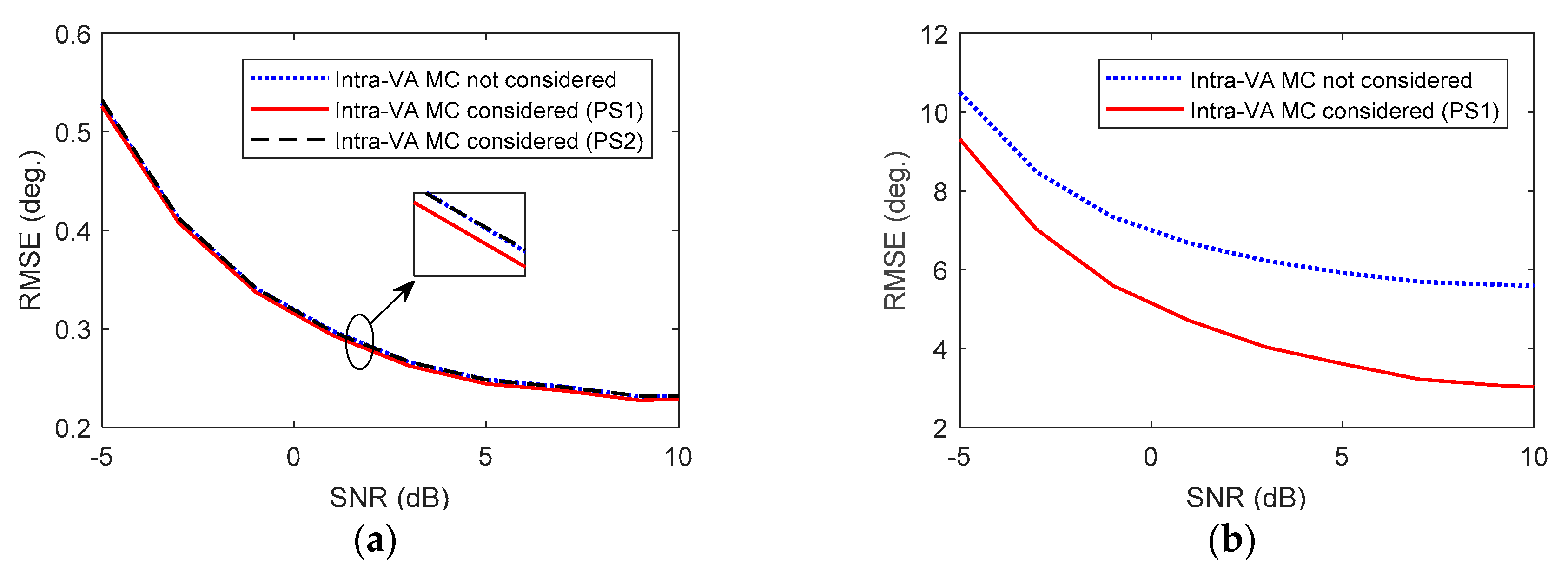
Consider four uncorrelated equal power signals from 45 ° , 10 ° , 10 ° , and 30 ° . All the signals have the same polarization state of ( 45 ° , 90 ° ) . The snapshot number is 500. The signal-to-noise ratio (SNR) varies from −5 dB to 10 dB. The performance of PS1 and PS2 in the alleviation of intra-VA MC was compared with the estimation results without considering intra-VA MC. Shown in Figure 6 are the root-mean-square error (RMSE) curves of the DOA and polarization parameter estimates (obtained by averaging the results of 1000 independent trials). It can be observed that the three schemes provided almost the same DOA estimation, but PS1, which considered the intra-VA MC, had slightly better performance than the others. Moreover, the polarization parameter estimation by PS1 was clearly superior to that by the scheme in which intra-VA MC was not considered. These results demonstrate that the proposed schemes are effective in dealing with intra-VA MC, especially for polarization parameter estimation.

5.2. Capability of Inter-VA MC Reduction

The function of ISC geometry in reducing the inter-VA MC was investigated and compared with some current sparse arrays. The arrays included 8 tri-polarized VAs, each of which was the same as the VAs used in Section 5.2. The VA positions of the ISC were 0, 2, 4, 6, 11, 16, 21, and 24. The sparse arrays compared included the MRA [24] (0, 1, 2, 11, 15, 18, 21, 23), the nested array [26] (1, 2, 3, 4, 5, 10, 15, 20), the super nested array [27] (1, 3, 4, 7, 10, 15, 19, 20), the coprime array [25] (0, 2, 4, 5, 6, 8, 10, 15), and the CADiS array [28] (0, 2, 4, 6, 8, 15, 20, 25). The manifolds of the compared arrays including inter-VA MC were generated by using the results of full-wave electromagnetic simulations.
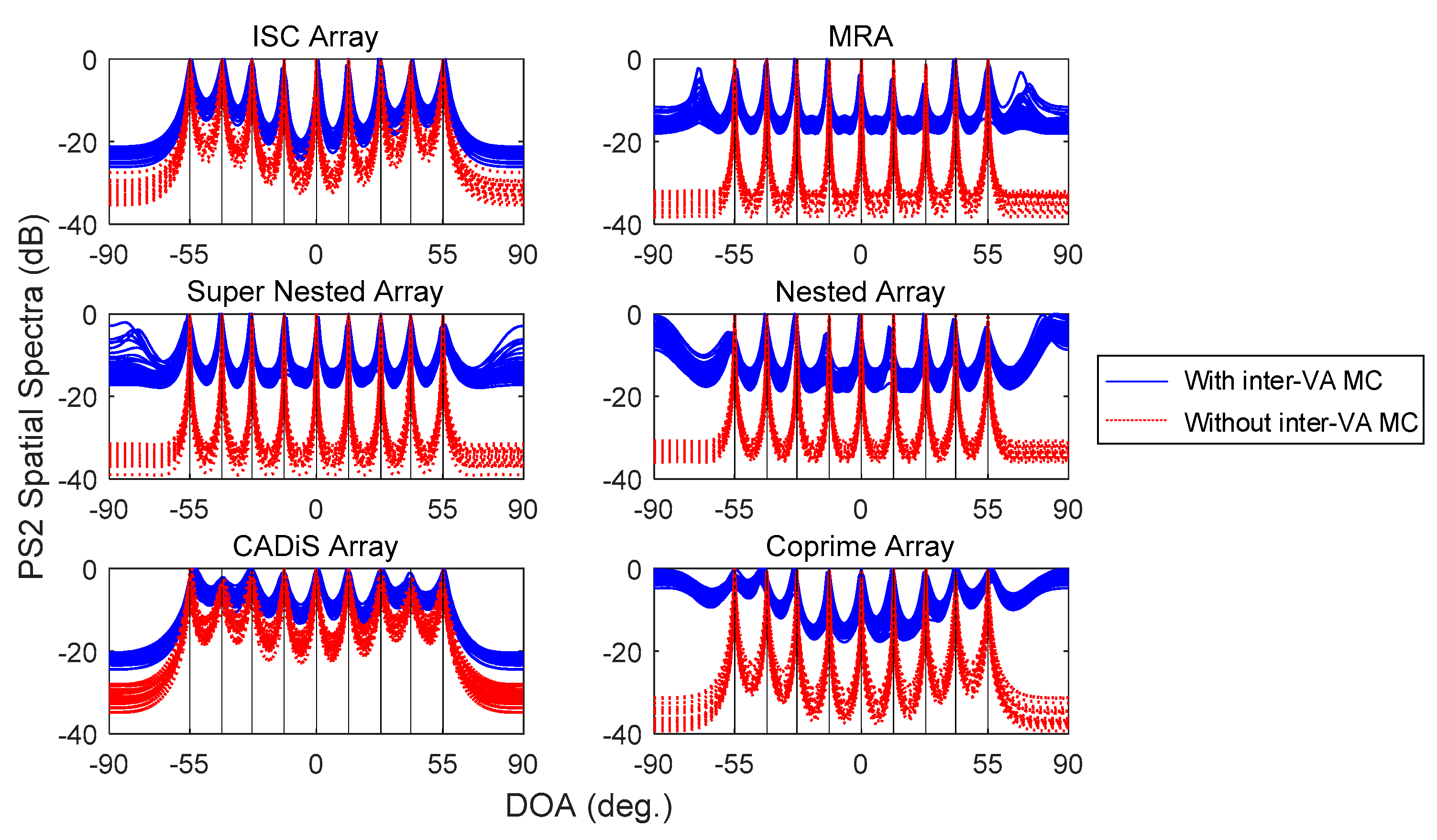
Consider nine uncorrelated equal power signals from 55 ° , 41 ° , 28 ° , 14 ° , 0 ° , 14 ° , 28 ° , 41 ° , and 55 ° . The SNR is 10dB. The snapshot number is 500. All the signals have the same polarization state of ( 45 ° , 90 ° ) . Shown in Figure 7 are the PS2 spatial spectra (100 independent runs) of the compared arrays in the presence of inter-VA MC. For comparison, the results assuming no inter-VA MC are also included in the figure. It is observed that, without inter-VA MC, all the six arrays can be used to obtain good DOA estimation, while CADiS appears to be the worst in terms of resolvability (its consecutive coarray aperture is shorter than that of the others). In the presence of inter-VA MC, the resolution capabilities and DOA estimation accuracies of the MRA, nested array, super nested array, and coprime array are observed to be degraded, possibly also exhibiting spurious peaks. The ISC and CADiS arrays are observed to be less deteriorated while the former is superior over the latter in terms of resolvability. Note that the compared arrays differ only in the VA spacing; the results demonstrate that, due to the VA spacing constraint of no less than one signal wavelength, ISC and CADiS involve less serious inter-VA mutual coupling in comparison with the other arrays.

5.3. Robustness Against VA Misalignment

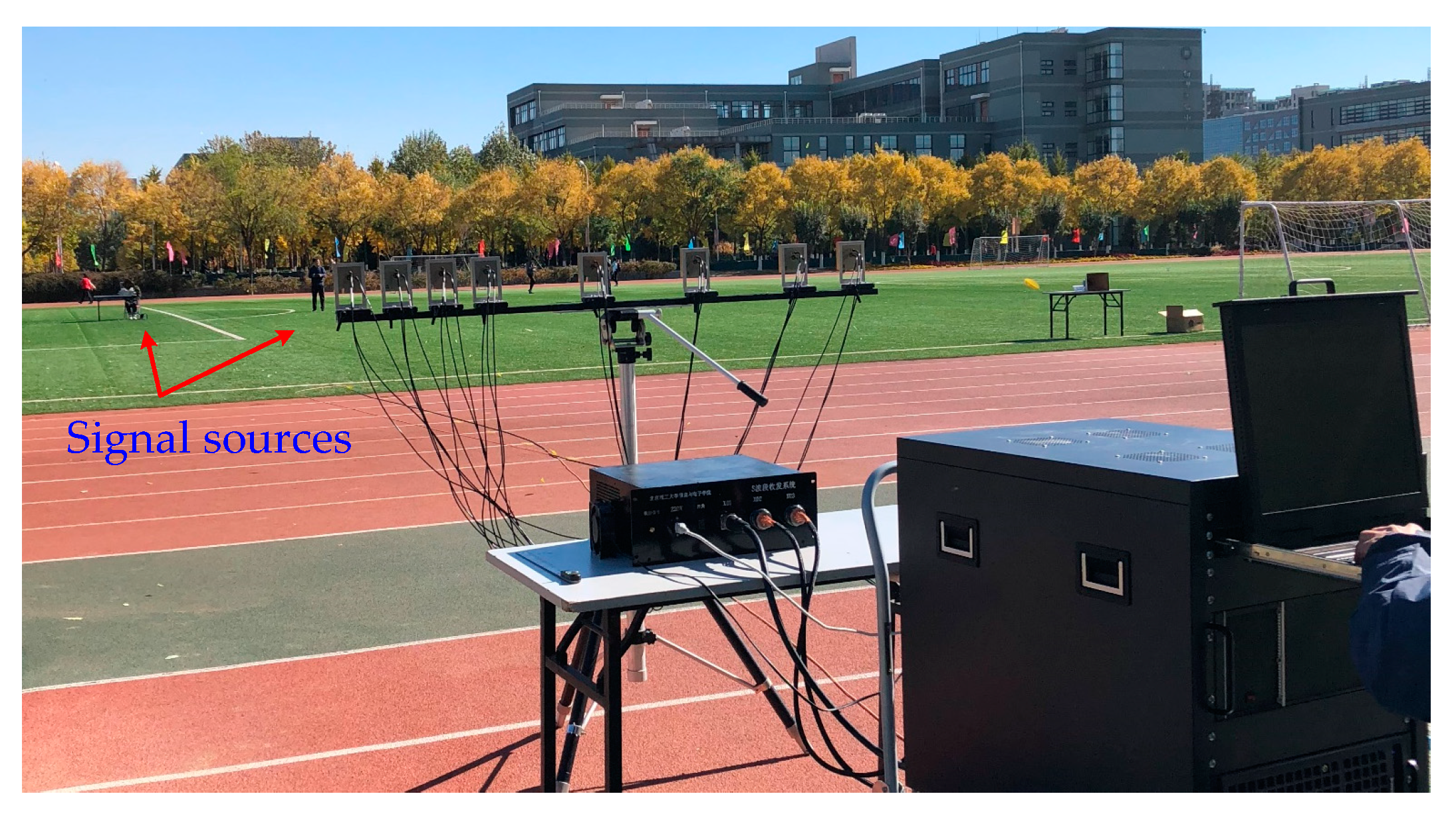
An S-band (2.4 GHz) 24-channel array system (including 8 tri-polarized VAs, see Figure 2) was developed, as shown in Figure 8. The VA positions of the system are adjustable.
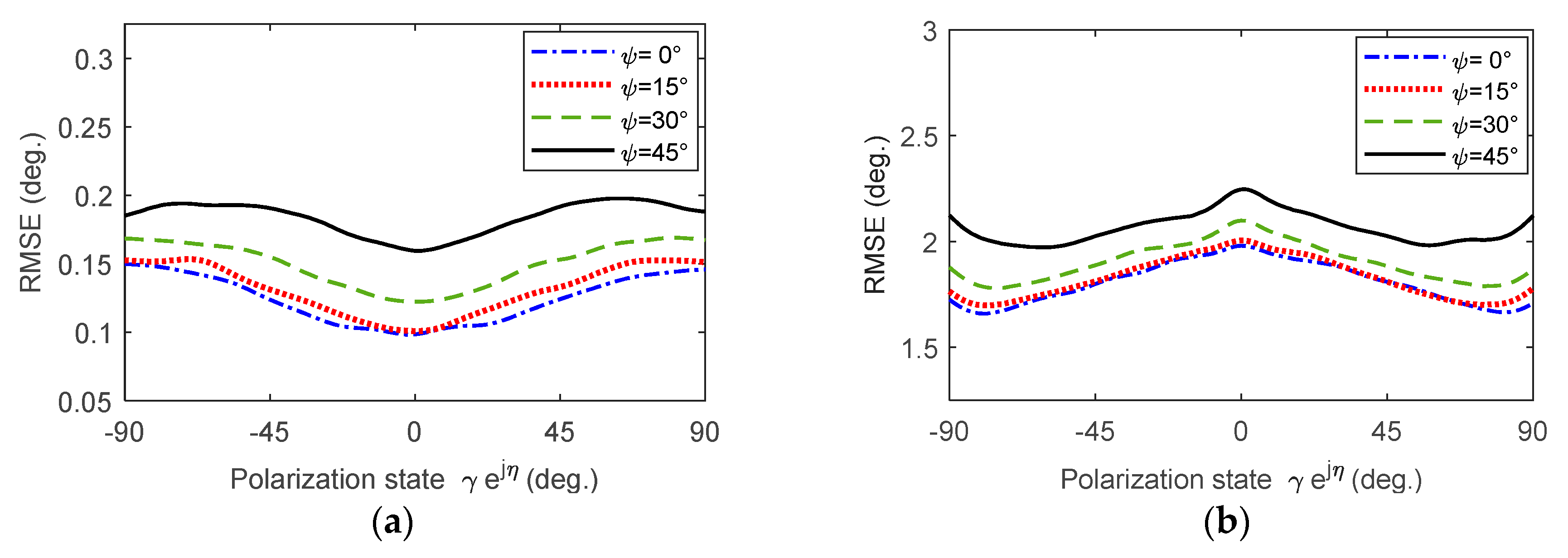
We investigated the robustness of the system against VA misalignment (causing different levels of signal–VA polarization mismatch) under a relatively simple condition: estimating the DOA and polarization parameter of a single linearly polarized signal with an 8-VA ISC array using the PS1 scheme. The VA positions were 0, 2, 4, 6, 11, 16, 21, and 24. The VA misalignment was characterized by the orientation angle of the monopole antenna measured from the x-o-y plane, denoted ψ . Here, 0 ° ψ 45 ° . The DOA of the signal was 45 ° . The signal auxiliary polarization angle γ varied over [ 0 ° , 90 ° ] while the signal polarization phase difference η was 0 ° or 180 ° . The SNR was 0 dB. The snapshot number was 50. Shown in Figure 9 are the RMSE curves of the DOA and auxiliary polarization angle estimates versus polarization variation (obtained by averaging the results of 10,000 independent trials). It was observed that the array system exhibits a good robustness against VA misalignment for signal parameter estimation. The satisfactory performance of PS1 in DOA estimation is also observed, although the polarization estimation performance is not so good.

5.4. Parameter Estimation Using Real-World Data

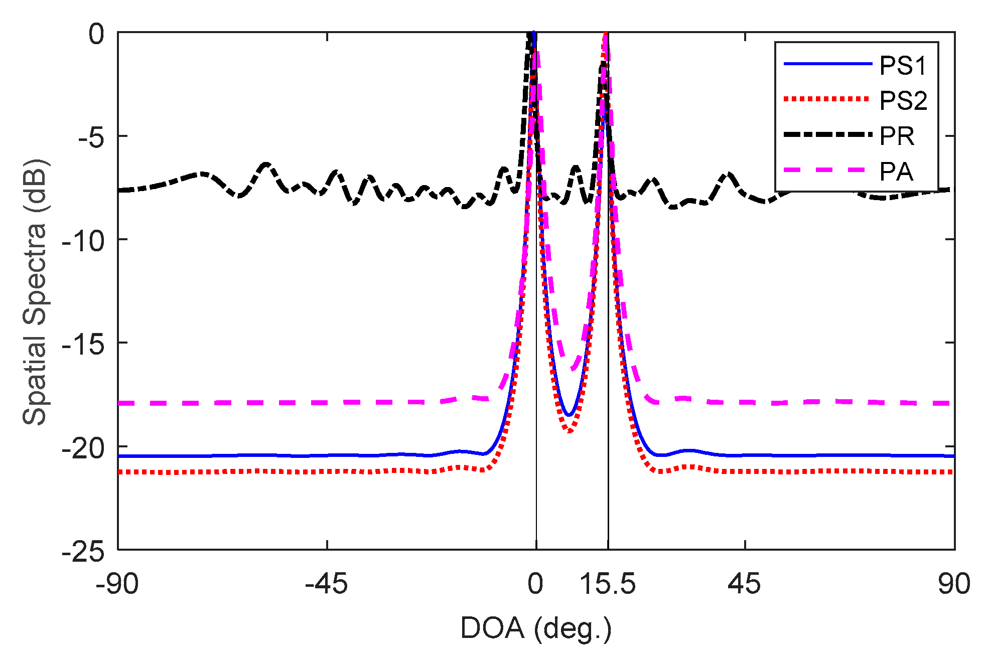
Data were collected from the array system mentioned in Section 5.3. As shown in Figure 6, two signal sources were placed about 40 m away from the array. One was a linearly polarized horn antenna (polarization of about ( 45 ° , 15 ° ) ); the other was an unmanned aerial vehicle (UAV) controller (polarization unknown). The DOAs of the radiated single tone signal (from the horn) and orthogonal quadrature phase shift keying modulated signal (from the UAV controller) were about 0 ° and 15 ° . The snapshot number was 1000. Displayed in Figure 10 are the spatial spectra of PS1 and PS2. For comparison, the results of the existing polarimetric rank reduction (PR) [4] and polarimetric average (PA) [9] methods are also included in the figure. The two signals can be observed to be well identified by all the methods, while PS1 and PS2 performed better than PR and PA. The polarization estimations obtained by PS1 were about ( 44.1 ° , 21.8 ° ) and ( 68.3 ° , 110.0 ° ) .

6. Conclusions

A new sparse tri-polarized VA array called ISC was designed for the alleviation of inter-VA mutual coupling. Moreover, two unambiguous direction finding and polarization estimation methods, called PS1 and PS2, were presented for ISC. The behavior of ISC with parameter estimation using PS1 and PS2 was illustrated using simulated data and real-world data measured by a practical tri-polarized ISC array system. The results show that ISC is a good candidate for practical direction finding, regarding inter-VA MC reduction as well as aperture extension.

Author Contributions

Conceptualization, S.S. and Y.X.; methodology, S.S.; software, S.S. and J.Z.; formal analysis, S.S.; investigation, S.S., Y.X., J.Z., K.Z. and Y.H.; writing—original draft preparation, S.S.; writing—review and editing, Y.X.; supervision, Y.X.; project administration, Z.L.; funding acquisition, Y.X. and Z.L.

Funding

This research was funded by the National Natural Science Foundation of China under Grant 61331019 and Grant 61490691.

Conflicts of Interest

The authors declare no conflict of interest.

Appendix A

Table A1. Some minimum-redundancy ISC array configurations.
NN0VA Locations
330 2 5
450 2 4 7
580 2 4 7 10
6130 2 4 9 12 15
7180 2 4 9 14 17 20
8230 2 4 9 14 19 22 25
9280 2 4 9 14 19 24 27 30
10330 2 4 6 8 13 20 25 32 35
11400 2 4 6 13 20 27 34 37 39 42
12480 2 4 6 8 10 19 24 35 40 47 50
13550 2 4 6 8 10 19 24 31 42 47 54 57
14640 2 4 6 8 17 22 35 40 47 56 59 63 66
15720 2 4 6 8 36 39 43 48 53 58 63 68 71 74
16830 2 4 6 8 10 17 24 44 49 54 59 70 73 82 85
17930 2 4 8 15 22 26 33 38 43 70 80 83 86 89 92 95
181030 2 4 6 8 10 43 52 54 63 68 75 80 87 92 99 102 105
191160 2 4 6 8 10 53 60 63 69 74 81 86 93 98 105 108 115 118
201290 2 4 6 8 10 61 68 75 79 82 91 94 103 106 115 118 123 128 131

References

  1. Compton, R.T., Jr. The tripole antenna: An adaptive array with full polarization flexibility. IEEE Trans. Antennas Propag. 1981, 29, 944–952. [Google Scholar] [CrossRef]
  2. Weiss, A.J.; Friedlander, B. Performance analysis of diversely polarized antenna arrays. IEEE Trans. Signal Process. 1991, 39, 1589–1603. [Google Scholar] [CrossRef]
  3. Nehorai, A.; Ho, K.C.; Tan, B.T.G. Minimum-noise-variance beamformer with an electromagnetic vector sensor. IEEE Trans. Signal Process. 1999, 47, 601–618. [Google Scholar] [CrossRef]
  4. Ferrara, E.R., Jr.; Parks, T.M. Direction finding with an array of antennas having diverse polarizations. IEEE Trans. Antennas Propag. 1983, 31, 231–236. [Google Scholar] [CrossRef]
  5. Li, J.; Compton, R.T., Jr. Angle and polarization estimation using ESPRIT with a polarization sensitive array. IEEE Trans. Antennas Propag. 1991, 39, 1376–1383. [Google Scholar] [CrossRef]
  6. Nehorai, A.; Paldi, E. Vector-sensor array processing for electromagnetic source localization. IEEE Trans. Signal Process. 1994, 42, 376–398. [Google Scholar] [CrossRef]
  7. Li, J.; Stoica, P.; Zheng, D. Efficient direction and polarization estimation with a COLD array. IEEE Trans. Antennas Propag. 1996, 44, 539–547. [Google Scholar] [CrossRef]
  8. Han, K.; Nehorai, A. Nested vector-sensor array processing via tensor modeling. IEEE Trans. Signal Process. 2014, 62, 2542–2553. [Google Scholar] [CrossRef]
  9. He, J.; Zhang, Z.; Shu, T.; Yu, W. Direction finding of multiple partially polarized signals with a nested cross-dipole array. IEEE Antennas Wirel. Propag. Lett. 2017, 16, 1679–1682. [Google Scholar] [CrossRef]
  10. Wong, K.T.; Yuan, X. “Vector cross-product direction-finding” with an electromagnetic vector-sensor of six orthogonally oriented but spatially noncollocating dipoles/loops. IEEE Trans. Signal Process. 2011, 59, 160–171. [Google Scholar] [CrossRef]
  11. Wong, K.T.; Song, Y.; Fulton, C.J.; Khan, S.; Tam, W. Electrically “long” dipoles in a collocated/orthogonal triad—for direction finding and polarization estimation. IEEE Trans. Antennas Propag. 2017, 65, 6057–6067. [Google Scholar] [CrossRef]
  12. Rao, S.; Chepuri, S.P.; Leus, G. DOA estimation using sparse vector sensor arrays. In Proceedings of the IEEE 6th International Workshop on Computational Advances in Multi-Sensor Adaptive Processing, Cancun, Mexico, 13–16 December 2015; pp. 333–336. [Google Scholar] [CrossRef]
  13. Shen, L.; Liu, Z.; Xu, Y. Parameter estimation using partly calibrated vector antennas. IEEE Antennas Wirel. Propag. Lett. 2017, 16, 860–863. [Google Scholar] [CrossRef]
  14. Elnour, B.; Erricolo, D. A novel colocated cross-polarized two-loop PCB antenna in the ISM 2.4-GHz band. IEEE Antennas Wirel. Propag. Lett. 2010, 9, 1237–1240. [Google Scholar] [CrossRef]
  15. Costa, M.; Richter, A.; Koivunen, V. DoA and polarization estimation for arbitrary array configurations. IEEE Trans. Signal Process. 2012, 60, 2330–2343. [Google Scholar] [CrossRef]
  16. Slater, M.J.; Schmitz, C.D.; Anderson, M.D.; Jones, D.L.; Bernhard, J.T. Demonstration of an electrically small antenna array for UHF direction-of-arrival estimation. IEEE Trans. Antennas Propag. 2013, 61, 1371–1377. [Google Scholar] [CrossRef]
  17. Lominé, J.; Morlaas, C.; Aubert, H. Novel vector sensors design with three co-located or distributed elements for the 3D DoA estimation. Prog. Electromagn. Res. B 2014, 57, 207–220. [Google Scholar] [CrossRef] [Green Version]
  18. Lominé, J.; Morlaas, C.; Imbert, C.; Aubert, H. Dual-band vector sensor for direction of arrival estimation of incoming electromagnetic waves. IEEE Trans. Antennas Propag. 2015, 63, 3662–3671. [Google Scholar] [CrossRef] [Green Version]
  19. Duplouy, J.; Morlaas, C.; Aubert, H.; Potier, P.; Pouliguen, P.; Djoma, C. Reconfigurable grounded vector antenna for 3-D electromagnetic direction-finding applications. IEEE Antennas Wireless Propag. Lett. 2018, 17, 197–200. [Google Scholar] [CrossRef]
  20. Liu, Z.; Li, R.; Li, B.; Liu, Y.; Lv, X. A wideband tri-polarized antenna at 2.4 GHz for array application. In Proceedings of the IEEE 6th Asia-Pacific Conference on Antennas and Propagation, Xi’an, China, 16–19 October 2017. [Google Scholar] [CrossRef]
  21. Friedlander, B. Antenna array manifolds for high-resolution direction finding. IEEE Trans. Signal Process. 2018, 66, 923–932. [Google Scholar] [CrossRef]
  22. Friedlander, B. Polarization sensitivity of antenna arrays. IEEE Trans. Signal Process. 2019, 67, 234–244. [Google Scholar] [CrossRef]
  23. Balanis, C.A. Antenna Theory, 4th ed.; John Wiley & Sons: Hoboken, NJ, USA, 2016; pp. 448–473. [Google Scholar]
  24. Moffet, A. Minimum-redundancy linear arrays. IEEE Trans. Antennas Propag. 1968, 16, 172–175. [Google Scholar] [CrossRef] [Green Version]
  25. Vaidyanathan, P.P.; Pal, P. Sparse sensing with co-prime samplers and arrays. IEEE Trans. Signal Process. 2011, 59, 573–586. [Google Scholar] [CrossRef]
  26. Pal, P.; Vaidyanathan, P. Nested arrays: A novel approach to array processing with enhanced degrees of freedom. IEEE Trans. Signal Process. 2010, 58, 4167–4181. [Google Scholar] [CrossRef] [Green Version]
  27. Liu, C.; Vaidyanathan, P.P. Super nested arrays: Linear sparse arrays with reduced mutual coupling Part I: Fundamentals. IEEE Trans. Signal Process. 2016, 64, 3997–4012. [Google Scholar] [CrossRef]
  28. Qin, S.; Zhang, Y.D.; Amin, M.G. Generalized coprime array configurations for direction-of-arrival estimation. IEEE Trans. Signal Process. 2015, 63, 1377–1390. [Google Scholar] [CrossRef]
  29. Wang, J.; Xu, H.; Leus, G.J.T.; Vandenbosch, G.A.E. Experimental assessment of the coarray concept for DoA estimation in wireless communications. IEEE Trans. Antennas Propag. 2018, 66, 3064–3075. [Google Scholar] [CrossRef]
  30. Robison, A.D. Parallel Computation of Sparse Rulers. Available online: https://software.intel.com/en-us/articles/parallel-computation-of-sparse-rulers (accessed on 10 April 2019).
  31. Ruf, C.S. Numerical annealing of low-redundancy linear arrays. IEEE Trans. Antennas Propag. 1993, 41, 85–90. [Google Scholar] [CrossRef]
  32. Dong, J.; Li, Q.; Jin, R.; Zhu, Y.; Huang, Q.; Gui, L. A method for seeking low-redundancy large linear arrays in aperture synthesis microwave radiometers. IEEE Trans. Antennas Propag. 2010, 58, 1913–1921. [Google Scholar] [CrossRef]
  33. Abramovich, Y.I.; Spencer, N.K.; Gorokhov, A.Y. Positive-definite Toeplitz completion in DOA estimation for nonuniform linear antenna arrays. II. Partially augmentable arrays. IEEE Trans. Signal Process. 1999, 47, 1502–1521. [Google Scholar] [CrossRef]
Figure 1. Coordinate system and schematic view of the tri-polarized vector antenna array.
Electronics 08 01557 g001
Figure 2. The tri-polarized antenna in the S-band 24-channel array system: (a) topology; (b) prototype.
Electronics 08 01557 g002
Figure 3. The gain pattern of the tri-polarized antenna.
Electronics 08 01557 g003
Figure 4. Two examples of an inter-VA spacing-constrained (ISC) array (“” denotes the physical vector antenna (VA), “•” denotes virtual VA, “×” denotes a gap): (a) ISC array with N = 8 , d N = 27 ; (b) ISC array with N = 8 , d N = 24 .
Electronics 08 01557 g004
Figure 5. Illustration of the two types of polarimetric subspace schemes (PS1: type-1 polarimetric subspace scheme, PS2: type-2 polarimetric subspace scheme, DOA: direction-of-arrival).
Electronics 08 01557 g005
Figure 6. Root-mean-square error (RMSE) versus signal-to-noise ratio (SNR): (a) DOA estimates; (b) polarization parameter estimates.
Electronics 08 01557 g006
Figure 7. The PS2 spatial specta of six 8-VA sparse arrays.
Electronics 08 01557 g007
Figure 8. Experimental setup of the S-band 24-channel array system.
Electronics 08 01557 g008
Figure 9. RMSE versus γ , η , and ψ : (a) DOA estimates; (b) auxiliary polarization angle estimates.
Electronics 08 01557 g009
Figure 10. Spatial spectra using real-world data (PR: polarimetric rank reduction method; PA: polarimetric average method).
Electronics 08 01557 g010
Table 1. Some inter-VA spacing-constrained (ISC) arrays for N = 8 .
LN0VA Locations
22200  2  4  6  11  14  19  22
23210  2  4  6  8  13  20  23
24220  2  4  6  11  16  21  24
25 1230  2  4  9  14  19  22  25
26210  3  6  9  17  19  21  26
27210  3  6  8  16  18  20  27
28210  2  8  10  16  19  23  28
29220  3  8  16  18  20  22  29
30230  5  7  9  19  22  25  30
31 2240  3  8  18  20  22  24  31
32220  2  4  11  16  19  22  32
33220  2  5  12  14  18  22  33
1 Minimum-redundancy ISC array. 2 Maximum-contiguous ISC array.