Abstract
The development and the experimental validation of a novel dynamic model of an islanded three-phase Inverter-based Microgrid (IMG) is presented in this paper. The proposed model reproduces the relevant system dynamics without excessive complexity and enough accuracy. The dynamics of the IMG are captured with a compact and scalable dynamic model, considering inverter based distributed generators with d-current droop primary and proportional resonant inner controllers. The complete development of the model, the practical assumptions, and the accurate proportional power sharing of the primary control technique are shown. The accuracy performance was verified in experiments performed at the Aalborg Intelligent Microgrids Laboratory for an islanded IMG case.
1. Introduction
As a result of the successful implementation of different policies to reduce greenhouse gas emissions and stimulate the integration of Renewable Energy Source (RES), total global installed power generation capacities based on solar and wind resources have grown significantly [1,2]. Most of the renewable power plants are small in terms of their generation capacities in comparison with the conventional fossil-fueled based power generators of the traditional power system [3]. As a consequence, these distributed generation units are typically connected to the medium and low voltage level of the distribution network [4]. Generation units, distributed energy storage systems, and RES can be grouped into clusters connected to the same distribution network and with a proper coordination and control architecture might operate as a microgrid. In this context, the microgrid concept has emerged as an important way to deal with the main challenges on the path to the new smart grid. Microgrids increase the penetration of renewable energy sources, reduce the environmental impact from the conventional power systems, support a new electric grid with better power quality supply, and present a higher efficiency [5].
A cluster of distributed generators, loads, and energy storage systems connected at the distribution level on a single connection point, with the functionality of coordinated operation to supply energy in grid-connected and islanded mode is known as a microgrid [5,6,7]. Fossil-fuel based generation technologies have been the conventional choice for the main energy source in isolated systems. However, the demonstrated technical and economical feasibility of RES based on wind, solar, hydrogen and hydro power has led to the integration of the renewable energy generation technologies as an essential requirement in the microgrid design [7]. The integration of these generation technologies normally requires power electronic interfaces (inverters) to connect the distributed generators to the AC-network [5]. A distributed generator interfaced using power electronics devices is known as an Inverter-based Distributed Generator (IDG), and when they are the most important generation sources in the microgrid, the system is commonly categorized as an IMG [6]. There are multiple potential benefits of implementing IMGs in the current power system; however, it implies the need to deal with new implementation and operation problems resulting from the integration of IDGs [8]. One of the most important challenges for the IMG design and operation is the accurate physical modeling of the system.
Effective and efficient analysis and simulation tools are needed for the smart grid; these simulation tools require the development of new dynamic models for IMGs with good accuracy performance and minimum complexity for new improved control techniques. The intensive use of power electronic devices and cybernetic components in the new smart IMG generates new modeling challenges, which must lead to models with a proper balance between complexity and accuracy. Considerable research has been undertaken to cope with the implementation issues of the IMG where the use of cybernetic components such as virtual components and communication systems is a common characteristic. On the other hand, significant research has been carried out aiming to find new accurate dynamic physical models for IMG [3]. However, these modeling proposals have not included cybernetic characteristics of the system and the complexity of the proposed models is a critical concern to achieve scalability for practical purposes. Associated with this gap in the literature, the standardization of cyber-physical IMG models has been scarcely explored.
This paper addresses this challenge and presents an experimental validation of a novel compact dynamic model for dq-reference frame-based primary controllers, using a systematic modeling methodology based on practical design assumptions. In this way, the development and experimental validation of a novel physical dynamic model of an islanded three-phase IMG is presented. The proposed model reproduces the relevant system dynamics without excessive complexity and with good accuracy. The dynamics of the IMG are captured with a compact and scalable dynamic model, considering inverter-based distributed generators with d-current droop primary and proportional resonant inner controllers. The complete development of the model, the practical assumptions, and the accurate proportional power sharing of the primary control technique are shown. The accuracy performance was verified in experiments performed at the Aalborg Intelligent Microgrids Laboratory for an islanded IMG case. The main contribution of this paper is the development of an IMG compact dynamic model with the following novel characteristics:
- Using a Kron reduced network, the interaction between IDGs and the line parameters have been included.
- The line characteristics have been adjusted with a dominant virtual impedance, which improves the accuracy of the model and the stability performance.
- With some practical design assumptions about the local controller tuning process, the inner controller dynamics have been neglected.
- The resulting model offers a compact form with low complexity and high accuracy, which is shown in an experimental validation.
- The implemented dq-reference frame-based primary controller leads to accurate proportional power sharing in steady-state.
1.1. Related Work
During the last decade, considerable research has been undertaken on modeling problem for IMGs. A first category of modeling approaches represents the interaction of a single IDG with the main grid, which typically is modeled by an infinite-bus bar, implying that the essential interactions between multiple connected units operating in island mode are not considered [9,10,11]. These modeling strategies neglect the dynamic interaction between IDGs, which results in low accuracy when reproducing the IMG system dynamics. More detailed modeling strategies have been proposed considering the IDG interactions in the network [3,12,13,14,15,16,17,18,19]. Early detailed modeling strategies propose detailed linearized 15th- and 36th-order mathematical state space models for the basic cases of two IDGs [12,13]. To decrease the complexity of the models, reduction methods have been proposed [3,14,15,16,17,18]. Most of the reduction strategies are based on the assumption that the IDGs are ideal voltage sources [14,17,18] or apply time-scale separation methods from an original linearized model [15,16]. Similarly, to represent dynamics in asymmetric operating conditions dynamic phasors-based modeling techniques have been proposed [20], which result in a model that is also able to reproduce the dynamics of unbalanced systems. However, all these proposals have been based on small-signal linearization techniques and have been applied to the conventional droop control primary controllers. A novel dq droop control technique is developed for the particular case of fixed frequency inverter-based AC microgrid [21]. Alternatively, a small-signal analysis for stable operation using virtual synchronous generator control is applied to the power electronic converters [22]. However, the analysis is limited to small perturbations and is not directly applicable to new primary and inner control techniques including Proportional Resonant (PR)-based controllers [23] and dq-reference frame control strategies [24,25]. Only a few recent works have explored large-signal modeling and stability analysis for IMGs [26], and they have addressed the modeling problem considering alternative primary control techniques [19].
1.2. Notation
The set of real numbers is denoted as and the non-negative real numbers as . denotes the set of natural numbers, the set of complex numbers, and . Bold style denotes column vectors (e.g., ), scalars are notated by a non-bold style (e.g., a), and the all-one vector as . The matrices are denoted with capital letters and particular element in matrix A is denoted as . The direct and inverse Clarke’s transformations are denoted as and , respectively [27]. The set of IDG in the IMG is denoted as , where .
1.3. Organization of the Paper
The paper is organized as follows. Section 2 introduces an overview of the IMG system including the IDG implementation. Next, the proposed dynamic modeling approach is presented in Section 3, which result in a novel compact dq-reference frame model. The experimental validation of the modeling technique and discussion are given in Section 4, and Section 5 provides some final conclusions and directions for future work in the physical modeling area.
2. System Overview
The architecture of an n IDG-IMG operating in island mode is represented in the three-phase circuit shown in Figure 1. The phase angle , and the amplitude describe completely the signal, where denotes the set of non-negative real numbers, and . In this way, describes a three-phase symmetric signal given by:
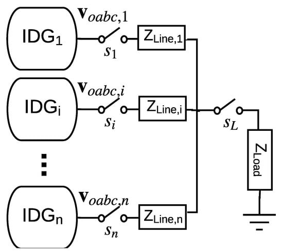
Figure 1.
Microgrid architecture: Three-phase island mode with multiple IDGs, mismatched lines parameters and a shared load.
Each IDG of the IMG consists of a physical power system, a virtual impedance loop, a PR-P inner controller and a d-current droop primary controller, as shown in Figure 2.
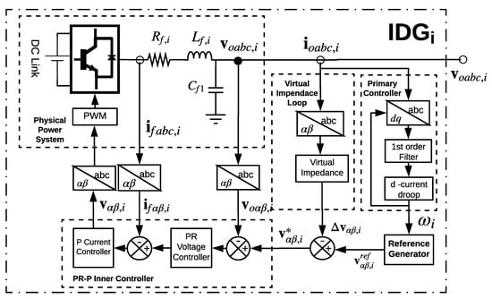
Figure 2.
Inverter-based distributed generator: Physical electric system and inner and primary controllers.
The reference generator block generates the signal:
The IDG implementation block diagram is shown in Figure 2, where the generator has two main components: a physical power system and a control system. The physical power system consists of a three-phase DC-AC converter, an LC filter, a Pulsewidth Modulation (PWM) block, and a DC Link, which we assume has its own internal controller and is not part of the discussion of this paper. On the other hand, the control system can be classified in two main control levels, namely: primary controller and inner controller.
2.1. Inner Controller
The instantaneous values of inductor currents (), and capacitor voltages () are measured and transformed to coordinates using the Clarke transformation [27]. These signals are used as control inputs to a double loop voltage inner controller. The voltage double loop inner controller uses a proportional current controller and a PR voltage controller in reference frame to track an reference signals, which is generated by the “Reference Generator” block. The voltage reference generator block produces the local reference voltage as:
where is the amplitude voltage reference value and . To simplify the notation, the vectors , are introduced. The voltage reference signal () is used as voltage reference input for the inner controller. The inner control architecture is based on a proportional resonant (PR) voltage loop and a proportional current loop, which is selected due to its zero steady state tracking error characteristics and simple implementation [23]. In addition, these control loops are designed to supply nonlinear currents to nonlinear loads and to suppress voltage harmonics produced by this kind of loads. A general scheme of the physical power system and the inner inverter controller is shown in Figure 3.
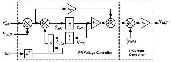
Figure 3.
PR-P inner controller.
2.2. Virtual Impedance Loop
Each IDG local controller implements a virtual impedance loop, where a dominant output impedance is emulated, where and are the virtual resistance and reactance parameters. The equivalent IDG circuit is presented in Figure 4. As we can see, the equivalent line impedance parameters can be defined as , where and . The virtual loop impedance is implemented in the stationary reference frame ( coordinates) as [23], and can be represented by:
where and are the measured inverter output currents in coordinates.
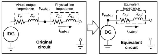
Figure 4.
IDG equivalent circuit.
Remark 1.
The virtual impedance parameters and can be selected with the rules: , and , where and are approximated line impedance parameters, computed using maximum line lengths and a typical line impedance. Note that this approach does not imply an accurate knowledge of the line parameter values.
2.3. Power Controller
One of the essential implementation requirements for the IMG operation is accurate proportional power sharing. To ensure proportional power sharing, each IDG of an islanded IMG should share the total load demand according to their ratings [28,29]. Therefore, the power sharing controller must guarantee that each IDG injects an amount of power proportional to its power rating and does not exceed its nominal capacity in steady state. In this context, a main control task in the IMG design is the power sharing control, which traditionally is defined as a primary level control task in the hierarchical control approach [30]. The concept of proportional sharing between the IDGs can be defined as follows [3]:
Definition 1.
Considering the parameters and as weighting factors and and the steady state active and reactive power outputs of the ith IDG, a proportional power sharing is achieved between two IDGs at nodes i and k with and if:
The parameters , , and can be defined as the per unit values of the active and reactive power ratings of each IDG. In this context, the control objective is to achieve proportional power sharing in the IMG, minimizing required communication infrastructure.
The primary level of control is in charge of supplying the reference signals to the inner control level. Traditionally, the main task of this control level is to achieve a proportional power sharing state according to Definition 1. Most of the available solutions for the active power sharing control for IMGs are based on the assumption of the relation between the active power and frequency. In this way, most of the previous works for active power sharing control have used the conventional droop control method as a primary controller. However, the implementation of the droop control implies considerable drawbacks including reactive power sharing inaccuracy, slow transient response and line parameters performance dependency. In this section, a novel Direct Current Primary Controller (DCPC) controller is proposed alternatively to the power droop control. Unlike conventional droop control architectures, the instantaneous active and reactive power measurements are not used as feedback control signals; instead, the instantaneous values of output currents are measured and transformed to dq-coordinates using reference frame theory transformations [31]. This controller is based on the assumption of implicit dependency between the active power injection with the measured direct current () in the synchronous reference frame [24,25]. Thus, the DCPC controller defines the reference signal generator variables as:
where is a proportional droop constant, is the nominal angular frequency, and is obtained as:
Next, a novel dynamic compact model is developed based on the IMG system described above.
3. Compact dq-Reference Frame Model for Inverter Based Microgrids
In this section, the main contributions of this paper are presented. Firstly, the IDG, load and physical-network modeling approaches are introduced and next the proposed compact model is developed.
3.1. IDG Model
To obtain a simplified IDG dynamic model, the following assumptions are introduced:
Assumption 1.
Each IDG implements a virtual impedance, where a dominant output impedance is emulated, where and are the virtual resistance and reactance parameters. and , where denotes the constant ohmic resistance, the constant inductance of the line of the ith branch, and are the virtual resistance and reactance parameters, and is the nominal frequency of the system.
Assumption 2.
The IDG operates with a fast and stable inner controller such that: , where is the input reference signal in coordinates of the inner controller.
The equivalent IDG circuit based on Assumption 1 is presented in Figure 4. As we can see, the equivalent line impedance parameters can be defined as , where and .
Additionally, based on Assumption 2, the inverter model can be represented by a generic dynamic system. In this way, the power system components and the inner controller of the IDG can be represented by a Voltage Controlled Source (VCS), where its three-phase symmetric output voltage is given by:
The variables , and can be defined by a higher-level control (primary control level in a conventional hierarchical control approach [30]), namely and, , where and . Note that , and it is assumed that the phase and output voltage regulation is instantaneous, as has been assumed in the previous literature [17,32].
3.2. Load Modeling
Following previous IMG modeling approaches [32,33], the loads in the IMG are assumed to be constant impedances, and a Kron network reduction is carried out to obtain a set of differential equations, eliminating all the algebraic equations of the passive nodes in the original network model [34]. In this way, constant impedance loads and a Kron reduced network model are assumed [33], where two IMG nodes i, and k are connected via an admittance , where and are the conductance and susceptance parameters, and is the set of complex numbers.
3.3. Network Model
Based on the IDG equivalent circuit, an electrical microgrid admittance matrix of the reduced network could be defined as the matrix , where: , and denotes the set of edges associated to node i. The current flows of the system can be expressed in dq-reference frame as [35]:
and
where
with the angle difference denoted as .
3.4. Compact dq-Reference Frame Model
A generalized current-flow model in dq-reference frame can be obtained as a function of the voltage nodal amplitudes ( and ) signals as [3]:
where , is the angle differences between the nodes i and k. The assumptions presented below are required to the compact dq-reference frame model derivation.
Assumption 3.
Defining as the angle difference, in a synchronized operation, is small enough to assume that and .
Assumption 4.
All the IDGs in the IMG have the same nominal amplitude voltage value .
Assumption 5.
The primary controller is designed such as the dynamics associated with the circuit components (distribution lines and loads), and the inner controllers are negligible compared to the dynamics of the other components in the IMG.
Using the load and network modeling approach presented previously, and considering Assumption 3, the current flow in dq-reference frame described by Equations (14) and (15) can be written as:
Considering Assumption 4, the current flow equations of the IMG can be written as:
Defining the angular frequency of the first IDG as the reference, and the state variable , from Equation (6), we can obtain a state space equation for as:
To achieve a compact representation of the IMG dynamic model, we use a vector-based formulation of the model. In this way, the following vectors are defined:
Additionally, the following matrices are defined as:
where matrices G and B are the conductance and susceptance matrices resulting from the Kron reduced network model described in Section 3.2 and Section 3.3. Thus, a compact model that represents the dynamics of an IMGs with n IDGs can be written in a compact form as:
4. Study Cases and Model Validation
The effectiveness and accuracy of the proposed model was verified via an experimental validation of a study case with two IDGs. The IMG architecture shown in Figure 1 is implemented in an experiment set-up at the Aalborg Intelligent Microgrids Laboratory [36], which is shown in Figure 5. The experimental setup consisted of two IDGs, implemented with commercial Danfoss 2.2 kW inverters and LC output filters, which emulated an islanded IMG with mismatched line parameters. The measurements were performed using LEM sensors, and the control algorithms were implemented on the real time platform dSPACE1106 board, which provided computing power for the real-time system and also functioned as an interface with the host PC and with the input/output boards. The control models were developed in Matlab/Simulink, compiled in C++, and ran on the DS1006 processor board of dSPACE real-time control platform. The system specifications are listed in Table 1.
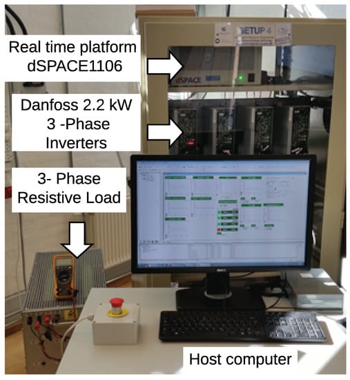
Figure 5.
Experiment setup: Compact dq-reference frame IMG model.

Table 1.
Microgrid Setup Parameters: Compact dq-reference frame IMG model validation.
An experimental case of two IDGs operating in island is presented in this section. In the initial state, the generators are operating synchronized without load. At , a resistive load () is suddenly connected and the transient response of the direct and quadrature current, as well as the frequency and amplitude voltage (approximated as the direct component of the voltage in dq-reference frame), are recorded by the dSCAPE real-time acquisition system. Figure 6, Figure 7, Figure 8 and Figure 9 show the transient response of the experiments (solid lines) and the transient simulation of the model represented by Equations (27)–(31) (dashed lines).
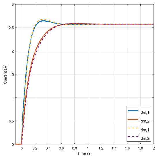
Figure 6.
Direct current transient responses (experimental results in solid lines and model simulation in dashed lines).
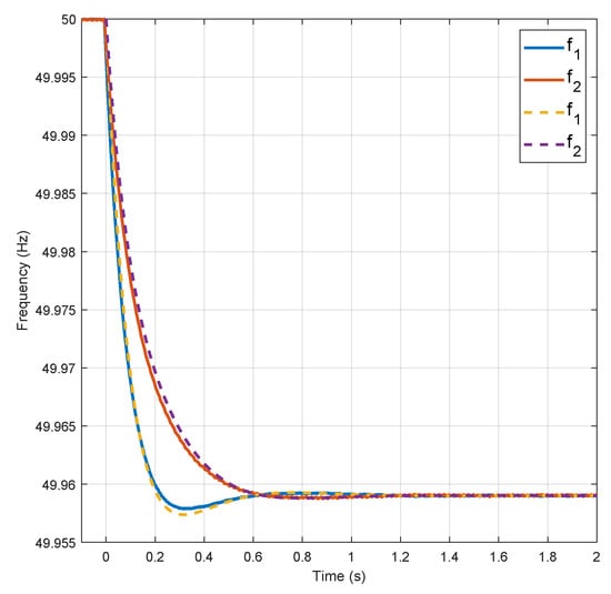
Figure 7.
Frequency transient responses (experimental results in solid lines and model simulation in dashed lines).
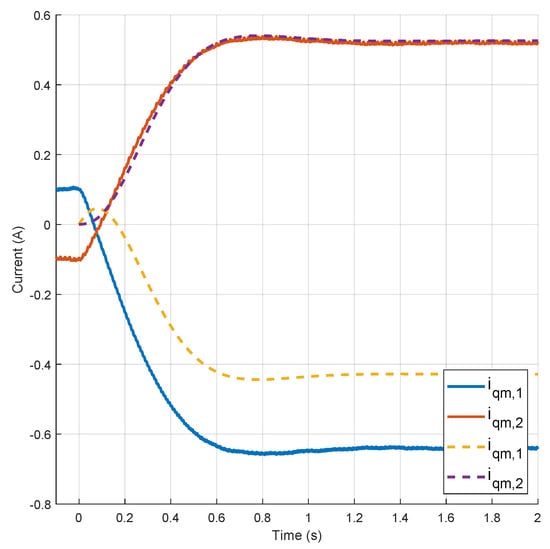
Figure 8.
Quadrature current transient responses (experimental results in solid lines and model simulation in dashed lines).
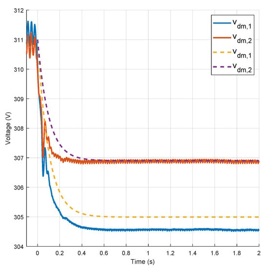
Figure 9.
Direct component of the output voltage transient response (experimental results in solid lines and model simulation in dashed lines).
In Figure 6 we can see that the compact model reproduces with accuracy the experimental response of the direct currents. Similarly, the transient behavior of the references frequencies of each IDGs is shown in Figure 7.
On the other hand, the transient response of the quadrature current components and the direct component of the output voltages are shown in Figure 8 and Figure 9. It is shown that the model of the quadrature current components and the output voltages representing Equations (27)–(31) captures the main settling time and dynamics. In these figures, we can observe that, although the transient simulation of the compact model captures the main settling time and dynamics, there are small offset errors between the experimental results and the model simulation for the second quadrature current and voltage signals ( and ). This situation can be the result of the low accuracy in the lecture from the hall sensors measurements and would be studied in future research.
5. Conclusions
A novel compact dynamic model of an IMG based on practical assumptions is presented. The transient simulation of the proposed model reproduces the relevant dynamics of the IMG without excessive complexity and with good accuracy on the output current and voltages dq-components of each IDG as well as their local frequency references. Unlike most of the previous approaches, the proposed model can capture dynamics under sudden load perturbations and can be scalable to practical scenarios with large amount of IDGs. Additionally, it is not limited to conventional primary droop control strategies and inner controllers. The presented cases were based on alternative d-current droop primary and PR double loop inner controllers to show the feasibility to reproduce dynamics of IDGs with non-conventional primary controllers. The accuracy performance is verified in experiments on a case of two IDGs islanded IMG.
In future work, the improvement of the model accuracy on the voltage and quadrature current dynamics will be investigated. Additionally, the integration of these new models to power system simulators to evaluate the impact on the transient stability of the new smart grid with high penetration of IDGs is an area for further research. In a similar way, the application of this modeling approach for stability analysis, control design are challenges that could be addressed.
Author Contributions
Conceptualization, Methodology, Software, Validation, Formal Analysis, and Investigation, C.A.M.; Resources, H.R.P., J.C.V., and J.M.G.; Writing—Original Draft Preparation, C.A.M.; Writing—Review and Editing, C.A.M., H.R.P., and E.M.-N.; Visualization, C.A.M.; Supervision, H.R.P., J.C.V. and J.M.G.; Project Administration, H.R.P.; and Funding Acquisition, H.R.P., J.C.V. and J.M.G.
Funding
This research was funded by the University of New South Wales, Tuition Fee Scholarship (RSRE7059 and RSRE7060) and the “Departamento Administrativo de Ciencia, Tecnología e Innovación” Scholarship Program No. 679-2014.
Conflicts of Interest
The authors declare no conflict of interest. The founding sponsors had no role in the design of the study; in the collection, analyses, or interpretation of data; in the writing of the manuscript, and in the decision to publish the results
Abbreviations
The following abbreviations are used in this manuscript:
| IMG | Inverter based Microgrid |
| IDG | Inverter based Distributed Generator |
| MGCC | Microgrid Central Controller |
| BESS | Battery Energy Storage System |
| RES | Renewable Energy Source |
| PV | Photovoltaic System |
| PWM | Pulsewidth Modulation |
| PR | Proportional Resonant |
| VCS | Voltage Controlled Source |
| CPS | Cyber Physical System |
References
- Jäger-Waldau, A. Snapshot of Photovoltaics—March 2017. Sustainability 2017, 9, 783. [Google Scholar] [CrossRef]
- Global Wind Statistics; Global Wind Energy Council: Washington, DC, USA, 2017.
- Schiffer, J.; Seel, T.; Raisch, J.; Sezi, T. Voltage Stability and Reactive Power Sharing in Inverter-Based Microgrids With Consensus-Based Distributed Voltage Control. IEEE Trans. Control Syst. Technol. 2015, 96–109. [Google Scholar] [CrossRef]
- Pepermans, G.; Driesen, J.; Haeseldonckx, D.; Belmans, R.; D’haeseleer, W. Distributed generation: Definition, benefits and issues. Energy Policy 2005, 33, 787–798. [Google Scholar] [CrossRef]
- Lasseter, R.H. Smart Distribution: Coupled Microgrids. Proc. IEEE 2011, 99, 1074–1082. [Google Scholar] [CrossRef]
- Andishgar, M.H.; Gholipour, E.; Hooshmand, R.A. An overview of control approaches of inverter-based microgrids in islanding mode of operation. Renew. Sustain. Energy Rev. 2017, 80, 1043–1060. [Google Scholar] [CrossRef]
- Olivares, D.E.; Cañizares, C.A.; Kazerani, M. A Centralized Energy Management System for Isolated Microgrids. IEEE Trans. Smart Grid 2014, 5, 1864–1875. [Google Scholar] [CrossRef]
- Bevrani, H.; Watanabe, M.; Mitani, Y. Microgrid Control: Concepts and Classification. In Power System Monitoring and Control; John Wiley & Sons, Inc.: Hoboken, NJ, USA, 2014; pp. 186–208. [Google Scholar] [CrossRef]
- Coelho, E.; Cortizo, P.; Garcia, P. Small signal stability for single phase inverter connected to stiff AC system. In Proceedings of the Conference Record of the 1999 IEEE Industry Applications Conference, Thirty-Forth IAS Annual Meeting (Cat. No.99CH36370), Phoenix, AZ, USA, 3–7 October 1999; Volume 4, pp. 2180–2187. [Google Scholar] [CrossRef]
- Guan, Y.; Vasquez, J.C.; Guerrero, J.M.; Coelho, E.A.A. Small-signal modeling, analysis and testing of parallel three-phase-inverters with a novel autonomous current sharing controller. In Proceedings of the 2015 IEEE Applied Power Electronics Conference and Exposition (APEC), Charlotte, NC, USA, 15–19 March 2015; pp. 571–578. [Google Scholar] [CrossRef]
- Hossain, M.J.; Pota, H.R.; Mahmud, M.A.; Aldeen, M. Robust Control for Power Sharing in Microgrids With Low-Inertia Wind and PV Generators. IEEE Trans. Sustain. Energy 2015, 6, 1067–1077. [Google Scholar] [CrossRef]
- Pogaku, N.; Prodanovic, M.; Green, T.C. Modeling, Analysis and Testing of Autonomous Operation of an Inverter-Based Microgrid. IEEE Trans. Power Electron. 2007, 22, 613–625. [Google Scholar] [CrossRef]
- Rasheduzzaman, M.; Mueller, J.A.; Kimball, J.W. An Accurate Small-Signal Model of Inverter- Dominated Islanded Microgrids Using dq Reference Frame. IEEE J. Emerg. Sel. Top. Power Electron. 2014, 2, 1070–1080. [Google Scholar] [CrossRef]
- Coelho, E.A.A.; Cortizo, P.C.; Garcia, P.F.D. Small-signal stability for parallel-connected inverters in stand-alone AC supply systems. IEEE Trans. Ind. Appl. 2002, 38, 533–542. [Google Scholar] [CrossRef]
- Luo, L.; Dhople, S.V. Spatiotemporal Model Reduction of Inverter-Based Islanded Microgrids. IEEE Trans. Energy Convers. 2014, 29, 823–832. [Google Scholar] [CrossRef]
- Rasheduzzaman, M.; Mueller, J.A.; Kimball, J.W. Reduced-Order Small-Signal Model of Microgrid Systems. IEEE Trans. Sustain. Energy 2015, 6, 1292–1305. [Google Scholar] [CrossRef]
- Simpson-Porco, J.W.; Dorfler, F.; Bullo, F. Synchronization and power sharing for droop-controlled inverters in islanded microgrids. Automatica 2013, 49, 2603–2611. [Google Scholar] [CrossRef]
- Pota, H.R. Droop control for islanded microgrids. In Proceedings of the 2013 IEEE Power and Energy Society General Meeting (PES), Vancouver, BC, Canada, 21–25 July 2013; pp. 1–4. [Google Scholar] [CrossRef]
- Leitner, S.; Yazdanian, M.; Mehrizi-Sani, A.; Muetze, A. Small-Signal Stability Analysis of an Inverter-Based Microgrid with Internal Model Based Controllers. IEEE Trans. Smart Grid 2017. [Google Scholar] [CrossRef]
- Guo, X.; Lu, Z.; Wang, B.; Sun, X.; Wang, L.; Guerrero, J.M. Dynamic Phasors-Based Modeling and Stability Analysis of Droop-Controlled Inverters for Microgrid Applications. IEEE Trans. Smart Grid 2014, 5, 2980–2987. [Google Scholar] [CrossRef]
- Toub, M.; Bijaieh, M.M.; Weaver, W.W.; Rush, D.R., III; Maaroufi, M.; Aniba, G. Droop Control in DQ Coordinates for Fixed Frequency Inverter-Based AC Microgrids. Electronics 2019, 8, 1168. [Google Scholar] [CrossRef]
- Zhang, B.; Yan, X.; Li, D.; Zhang, X.; Han, J.; Xiao, X. Stable operation and small-signal analysis of multiple parallel DG inverters based on a virtual synchronous generator scheme. Energies 2018, 11, 203. [Google Scholar] [CrossRef]
- Vasquez, J.C.; Guerrero, J.M.; Savaghebi, M.; Eloy-Garcia, J.; Teodorescu, R. Modeling, Analysis, and Design of Stationary-Reference-Frame Droop-Controlled Parallel Three-Phase Voltage Source Inverters. IEEE Trans. Ind. Electron. 2013, 60, 1271–1280. [Google Scholar] [CrossRef]
- Guan, Y.; Guerrero, J.M.; Zhao, X.; Vasquez, J.C.; Guo, X. A New Way of Controlling Parallel-Connected Inverters by Using Synchronous-Reference-Frame Virtual Impedance Loop-Part I: Control Principle. IEEE Trans. Power Electron. 2016, 31, 4576–4593. [Google Scholar] [CrossRef]
- Macana, C.A.; Pota, H.R. Adaptive synchronous reference frame virtual impedance controller for accurate power sharing in islanded ac-microgrids: A faster alternative to the conventional droop control. In Proceedings of the 2017 IEEE Energy Conversion Congress and Exposition (ECCE), Cincinnati, OH, USA, 1–5 October 2017; pp. 3728–3735. [Google Scholar] [CrossRef]
- Kabalan, M.; Singh, P.; Niebur, D. Large Signal Lyapunov-Based Stability Studies in Microgrids: A Review. IEEE Trans. Smart Grid 2017, 8, 2287–2295. [Google Scholar] [CrossRef]
- Czarnecki, L. Instantaneous Reactive Power p-q Theory and Power Properties of Three-Phase Systems. IEEE Trans. Power Deliv. 2006, 21, 362–367. [Google Scholar] [CrossRef]
- Li, Y.; Li, Y.W. Power Management of Inverter Interfaced Autonomous Microgrid Based on Virtual Frequency-Voltage Frame. IEEE Trans. Smart Grid 2011, 2, 30–40. [Google Scholar] [CrossRef]
- IEEE. IEEE Standard for Interconnecting Distributed Resources with Electric Power Systems; IEEE Std 1547-2003; IEEE: New York, NY, USA, 2003; pp. 1–28. [Google Scholar]
- Guerrero, J.M.; Chandorkar, M.; Lee, T.L.; Loh, P.C. Advanced Control Architectures for Intelligent Microgrids. Part I: Decentralized and Hierarchical Control. IEEE Trans. Ind. Electron. 2013, 60, 1254–1262. [Google Scholar] [CrossRef]
- De Brabandere, K.; Bolsens, B.; Van den Keybus, J.; Woyte, A.; Driesen, J.; Belmans, R. A Voltage and Frequency Droop Control Method for Parallel Inverters. IEEE Trans. Power Electron. 2007, 22, 1107–1115. [Google Scholar] [CrossRef]
- Schiffer, J.; Ortega, R.; Astolfi, A.; Raisch, J.; Sezi, T. Conditions for stability of droop-controlled inverter-based microgrids. Automatica 2014, 50, 2457–2469. [Google Scholar] [CrossRef]
- Simpson-Porco, J.W.; Dörfler, F.; Bullo, F. Voltage Stabilization in Microgrids via Quadratic Droop Control. IEEE Trans. Autom. Control 2017, 62, 1239–1253. [Google Scholar] [CrossRef]
- Dörfler, F.; Bullo, F. Kron reduction of graphs with applications to electrical networks. IEEE Trans. Circuits Syst. I Regul. Pap. 2013, 60, 150–163. [Google Scholar] [CrossRef]
- Schiffer, J.; Zonetti, D.; Ortega, R.; Stanković, A.M.; Sezi, T.; Raisch, J. A survey on modeling of microgrids—From fundamental physics to phasors and voltage sources. Automatica 2016, 74, 135–150. [Google Scholar] [CrossRef]
- Meng, L.; Luna, A.; Diaz, E.; Sun, B.; Dragicevic, T.; Savaghebi, M.; Vasquez, J.; Guerrero, J.; Graells, M. Flexible System Integration and Advanced Hierarchical Control Architectures in the Microgrid Research Laboratory of Aalborg University. IEEE Trans. Ind. Appl. 2015, 52. [Google Scholar] [CrossRef]
© 2019 by the authors. Licensee MDPI, Basel, Switzerland. This article is an open access article distributed under the terms and conditions of the Creative Commons Attribution (CC BY) license (http://creativecommons.org/licenses/by/4.0/).