1. Introduction
1.1. Industrial Context and Problem Statement
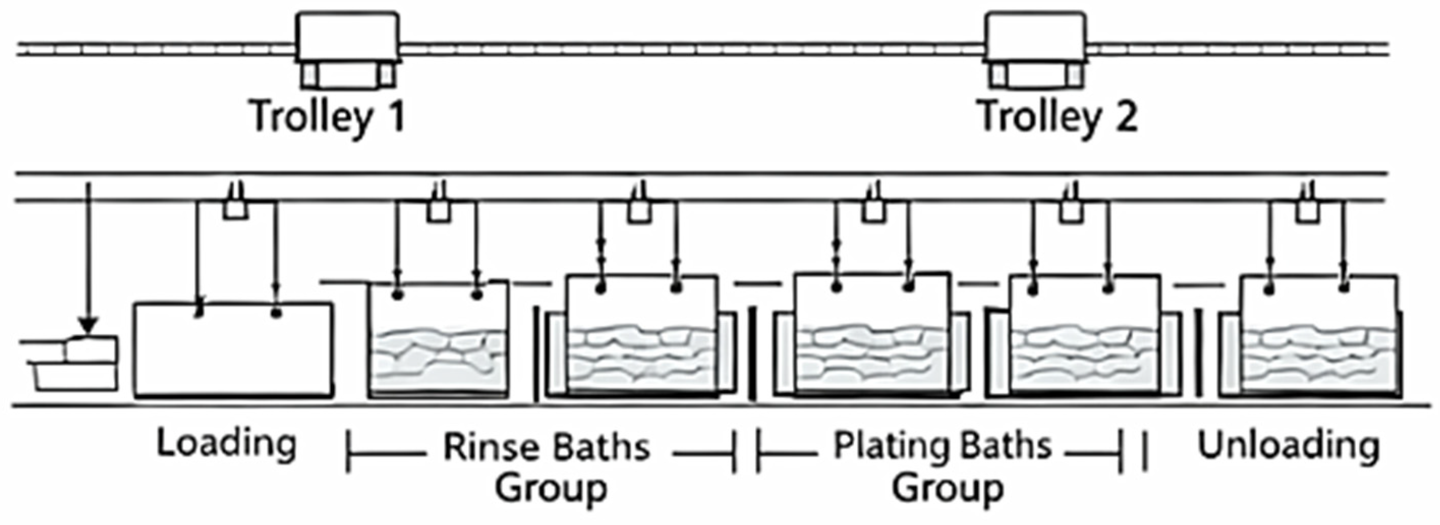
Industrial electroplating lines remain among the most demanding environments for reliable digital automation. In contrast to clean or enclosed manufacturing systems, electroplating plants operate under continuous exposure to corrosive vapors, elevated humidity, conductive residues, and strong electromagnetic interference generated by motors, relays, and contactors. Under such conditions, the control layer must preserve deterministic execution, signal reliability, and fail-safe motion behavior while still supporting production efficiency and process continuity.
Many legacy electroplating lines still rely on rigid sequential control, relay-dominant logic, or centralized PLC implementations with limited runtime adaptability. Such architectures are often adequate for fixed process routing, but they become restrictive when the plant contains both unique and redundant technological baths and when multiple transport units share the same mechanical corridor. In the line addressed in this paper, two autonomous trolleys move on a common rail path and serve an 18-station electroplating process. Under this configuration, the controller must preserve safe trolley separation, maintain correct technological dwell times, and exploit redundant process stations without introducing ambiguity into execution flow.
Static one-to-one mapping between a technological step and a fixed bath is poorly suited to this operating mode. It serializes production unnecessarily, underuses available parallel bath capacity, and creates bottlenecks even when equivalent stations are physically available. The effect is most pronounced in grouped zinc-plating and passivation sections, where inadequate runtime allocation leads directly to longer trolley idle intervals, unbalanced bath usage, and reduced throughput. The problem addressed here is therefore not simply one of trolley motion, but one of embedded coordination and resource allocation under strict industrial safety constraints. The overall operating context of the electroplating line is shown in
Figure 1.
1.2. Motivation for a Deterministic Microcontroller-Based Architecture
The control architecture developed in this work is centered on the ATmega2560 microcontroller (Microchip Technology Inc., Chandler, AZ, USA). The objective is not merely low-cost implementation, but a demonstration that adaptive and safety-layered electroplating control can be realized on a compact embedded platform without dependence on a heavier runtime environment. The controller integrates plant-side sensing, trolley coordination, grouped-resource handling, thermal supervision, and local diagnostics within one deterministic execution structure.
A central design decision is the use of discrete station-referenced positioning instead of dependence on cumulative continuous motion estimation. In electroplating lines, encoder-dominant localization is vulnerable to slippage, contamination, mechanical wear, and loss of coupling between measured and actual displacement. The proposed system reconstructs trolley position from binary-coded workstation-referenced sensor states, yielding absolute position information at the station level. This is better aligned with the process itself, since technological validity depends on correct alignment above discrete baths rather than on continuous path reconstruction.
A second design decision is the replacement of static bath addressing by runtime resource allocation. In conventional control schemes, a technological step is tied to one predefined bath. In the present architecture, equivalent baths are abstracted into virtual process groups, and the physical destination is selected at runtime according to availability and safety constraints. Retrieval from grouped baths is governed by temporal FIFO logic, so that unloading follows process-completion readiness rather than fixed order of entry. This allows redundant plant capacity to be used more effectively without compromising dwell-time correctness.
A third design driver is safety. Electroplating automation combines shared trolley motion, vertical lifting mechanisms, heated baths, chemical exposure, and operator-accessible industrial space. Under these conditions, safe operation cannot rely on a single protective layer. The proposed controller therefore combines predictive pre-start verification, runtime software arbitration, and independent hardware-wired normally closed interlocks. Unsafe command sequences are rejected before execution, unsafe runtime states are blocked during operation, and critical stop conditions remain enforceable at the hardware level.
1.3. Objectives, Contributions, and Paper Organization
The primary contribution of this work is the development of a plant-side embedded control architecture that integrates asynchronous execution, grouped-resource allocation, readiness-based retrieval, and layered safety within a deterministic implementation suitable for resource-constrained embedded platforms.
The main contributions of the paper are as follows:
A deterministic asynchronous control model for shared-track dual-trolley operation, in which each trolley advances according to local execution conditions rather than a globally blocking sequence;
A grouped-resource allocation mechanism based on virtual process groups, enabling runtime selection of equivalent baths instead of rigid fixed-address process execution;
A temporal FIFO retrieval strategy that preserves dwell-time integrity by selecting completed units according to readiness time rather than static entry order;
A compact embedded process representation suitable for EEPROM-based execution on a resource-constrained controller;
A layered safety architecture integrating predictive validation, runtime arbitration, and hardware-wired fail-safe interruption within one controller.
The work addresses a specific gap between high-level scheduling concepts and plant-side industrial control. Rather than proposing a supervisory optimization framework detached from execution, it presents a directly deployable embedded architecture for harsh electroplating environments, where adaptive coordination, process correctness, and fail-safe behavior must coexist under strict implementation constraints.
The remainder of the paper is organized as follows.
Section 2 reviews related work in industrial digital modernization, intelligent manufacturing architectures, multi-agent coordination, and embedded validation.
Section 3 defines the system model and control principles.
Section 4 presents the hardware architecture and electronic implementation.
Section 5 describes the firmware architecture and control algorithm.
Section 6 addresses implementation details and code-level consistency.
Section 7 defines the experimental setup and validation protocol.
Section 8 presents the results and discussion.
Section 9 outlines the limitations and future work.
Section 10 concludes the paper.
2. Related Work
2.1. IIoT and Modernization of Legacy Industrial Lines
The modernization of legacy industrial systems has become a central topic of Industry 4.0, IIoT, and cyber-physical manufacturing research [
1,
2,
3,
4,
5,
6,
7]. These studies show that older production lines are no longer evaluated only by basic automation capability, but also by connectivity, adaptability, operational transparency, and compatibility with higher-level digital services [
1,
2,
3,
4,
5]. This is especially relevant in process industries, where production assets often remain in operation for long periods and modernization is performed incrementally rather than through complete plant replacement [
6,
7].
In many practical cases, however, modernization is concentrated at the supervisory level. Communication interfaces, monitoring functions, and data visibility are added, while the low-level execution logic remains rigid [
1,
2,
3,
4,
5,
6,
7]. In electroplating lines, this limitation is more severe because the plant operates in a chemically aggressive and electromagnetically noisy environment. Under such conditions, modernization must address not only information integration, but also the structure of the embedded controller responsible for motion, process timing, resource allocation, and safety.
The present work addresses this lower execution layer directly. Its focus is not supervisory digitalization alone, but the restructuring of plant-side control logic for an electroplating line derived from an industrial layout with shared-track transport, grouped process resources, and strict fail-safe requirements.
2.2. Digital Twins, Intelligent Manufacturing, and Scheduling-Oriented Architectures
Recent work on digital twins, intelligent manufacturing systems, and AI-assisted scheduling has established a strong conceptual basis for adaptive industrial operation [
8,
9,
10,
11,
12,
13,
14,
15,
16]. Digital-twin research has shown how virtual plant representations can support monitoring, prediction, optimization, and process-level decision-making [
8,
9,
10,
11,
12,
13,
14,
15]. In parallel, scheduling research has expanded toward adaptive, AI-supported, and data-driven methods for routing, sequencing, and flexible resource use [
11,
12,
14,
16].
These developments are relevant because they show that fixed-sequence control is increasingly inadequate in complex manufacturing environments. Adaptive production now depends on better use of available resources, runtime awareness of process state, and tighter coupling between planning and execution [
8,
9,
10,
11,
12,
13,
14,
15,
16]. This broader direction is fully aligned with the motivation of the present work.
A different issue emerges at the plant-side execution level. Most digital-twin and intelligent-scheduling frameworks operate above the embedded controller and assume that the physical execution layer can absorb optimization decisions without major structural constraints [
8,
9,
10,
11,
12,
13,
14,
15,
16]. That assumption is not valid for the electroplating line studied here. The controller must coordinate two trolley agents on a shared track, select grouped baths safely at runtime, preserve process dwell times, and maintain deterministic behavior on a compact embedded platform. The present work therefore addresses a different layer of the problem: not supervisory optimization, but execution-consistent embedded realization.
2.3. Multi-Agent Coordination and Hoist Scheduling in Electroplating and Flexible Production Systems
The literature on multi-agent manufacturing systems and hoist scheduling is directly relevant to the present study. Multi-agent approaches have long been recognized as effective in shop-floor environments requiring distributed decision-making, local autonomy, and dynamic coordination [
17,
18,
19,
20,
21]. These works show that distributed execution can improve responsiveness relative to rigid centralized sequencing, particularly when several resources compete for shared process space.
Hoist scheduling in electroplating and related wet-process lines forms an even closer research background [
22,
23,
24,
25,
26,
27,
28,
29,
30]. Foundational studies formulated the hoist scheduling problem under timing and motion constraints [
22,
23,
24]. Later work extended this direction through cyclic scheduling, genetic algorithms, logical formulations, and heuristic or combinatorial optimization strategies [
25,
26,
27,
28,
29,
30]. Collectively, these studies confirm that electroplating control cannot be reduced to simple transport logic: it involves the interaction of timing, allocation, and movement constraints across multiple process stations.
The main distinction lies in the execution level and integration scope. Much of the hoist-scheduling literature formulates electroplating coordination as a mathematical, logical, or heuristic scheduling problem and evaluates performance primarily at planning or scheduling level [
22,
23,
24,
25,
26,
27,
28,
29,
30]. The present work does not claim to replace or supersede that literature. Its contribution is narrower and implementation-oriented: it demonstrates how shared-track dual-trolley coordination, grouped bath assignment, dwell-time-aware retrieval, and layered safety can be realized coherently within a deterministic plant-side embedded controller under industrially constrained execution conditions.
A second distinction concerns the role of redundant baths in the controller itself. While flexible resource use appears in several scheduling studies [
27,
28,
29,
30,
31,
32], the present work integrates virtual process groups and temporal FIFO directly into the embedded execution logic rather than treating grouped-resource handling as the output of an external optimization layer. The novelty claim of this paper is therefore not the general existence of hoist scheduling or flexible bath allocation, but the implementation-consistent embedded realization of these principles together with station-referenced positioning, controller-level safety layering, and controller-centered HIL validation.
2.4. Embedded Validation and Hardware-Oriented Verification Approaches
Industrial control architectures require validation that remains close to real execution conditions. For that reason, hardware-in-the-loop and controller-oriented verification methods provide an important methodological background [
33,
34]. These approaches are especially relevant when timing behavior, conflict prevention, and safe response must be assessed under implementation-constrained conditions rather than only in conceptual simulation.
For the electroplating controller studied here, the key issue is not the adoption of a generic HIL framework as an end in itself. The critical requirement is that validation remain tied to the actual firmware logic, grouped-bath semantics, station-based movement model, and safety behavior of the target embedded controller implementation. This is why the present study uses a controller-centered validation approach rather than a detached algorithm-only benchmark [
33,
34].
That distinction is methodologically important. The contribution of this paper depends on showing that asynchronous execution, grouped-resource allocation, and predictive safety checks operate coherently in the implemented controller, not only in a scheduling abstraction.
2.5. Research Gap and Position of the Present Work
The reviewed literature places the present study at the intersection of four established research directions: industrial digital modernization [
1,
2,
3,
4,
5,
6,
7], intelligent and digital-twin-supported manufacturing [
8,
9,
10,
11,
12,
13,
14,
15,
16], multi-agent coordination [
17,
18,
19,
20,
21], and hoist or wet-line scheduling [
22,
23,
24,
25,
26,
27,
28,
29,
30,
31,
32], with controller-oriented validation providing the methodological basis [
33,
34]. Together, these domains explain why adaptive electroplating control is needed and what conceptual tools are available.
A clear underexplored area remains at the embedded execution layer. While the reviewed literature provides important results in industrial digitalization, intelligent scheduling, multi-agent coordination, and hoist-planning formulations, it gives less attention to implementation-consistent plant-side realization for electroplating lines that simultaneously involve two autonomous trolleys on a shared track, grouped redundant baths, station-referenced positioning, compact recipe encoding, readiness-based grouped-bath retrieval, and layered predictive/software/hardware safety enforcement.
The present work addresses this embedded execution problem directly. Its contribution is not a general digital-manufacturing framework nor a claim of global scheduling optimality. Rather, it is a plant-side embedded control architecture that translates adaptive coordination principles into executable electroplating control under harsh industrial constraints and validates that architecture in a controller-centered HIL setting. The position of the proposed system relative to the reviewed literature is summarized in
Table 1.
3. System Model and Control Principles
3.1. Electroplating Line as a Discrete Shared-Track Multi-Agent System
The electroplating line is modeled as a discrete transport-and-process system with 18 station-aligned positions and two autonomous trolley agents operating on a shared rail path. This configuration differs substantially from a simple transfer mechanism because trolley motion, bath occupancy, process dwell time, and retrieval order are coupled. The controller must therefore coordinate movement and process execution simultaneously rather than treat them as independent layers.
Let the ordered set of stations be defined as
where each station
denotes a discrete physical position associated with a bath, transfer location, or process-related point on the line. The transport units are represented as trolley agents
which share the same horizontal movement corridor. At any instant, each trolley is characterized by its current station-aligned position, the technological step being executed, the assigned target, and the local execution phase.
The control problem has three coupled components. The first is shared-track motion safety, since both trolleys may attempt to occupy neighboring or conflicting spatial regions. The second is process validity, since drum immersion and retrieval must satisfy technological dwell constraints. The third is resource allocation, since part of the line contains redundant baths that are technologically equivalent but physically distinct. These three components define the line as a constrained discrete-event multi-agent system rather than as a fixed sequential transport routine.
3.2. Asynchronous Finite-State Execution Model
The proposed architecture adopts an asynchronous finite-state execution model in which each trolley is represented as an independent embedded software agent evaluated within the main control loop without global blocking [
2,
3]. This is one of the central design principles of the original work and one of the key differences relative to conventional sequential control used in many legacy electroplating systems. Under a rigid global sequence, one trolley may unnecessarily delay the other even when the second trolley is physically free to move or process another technological step. In the present architecture, such global waiting is avoided by assigning a local execution state to each trolley.
For trolley
, the local runtime state may be expressed as
where:
is the current station-aligned position;
is the technological task pointer;
is the current execution phase;
is the logical target or process-group identifier;
is the assigned physical station when grouped resources are used;
is the readiness or completion state of the active process step.
This structure reflects the actual control logic used in the firmware. Each trolley maintains its own local execution state and is evaluated cyclically inside the same deterministic control loop. The controller therefore avoids global waiting conditions that are typical of rigid sequential electroplating control.
At system level, the main execution phases are:
initialization and homing;
task decoding and target resolution;
motion toward the assigned station;
drum lowering and process execution;
dwell completion and retrieval;
transition to the next technological step.
The implementation-oriented version of these phases is defined later in
Section 5, where the operational FSM phases and transition conditions are presented in detail. At the modeling level, the essential point is that trolley progression is local, event-driven, and constrained by shared safety and process conditions.
3.3. Bitwise Representation of Technological Steps
The controller stores and interprets technological recipes using a compact byte-level command structure suitable for EEPROM-based execution on a resource-constrained embedded platform. Each stored command contains both routing-related information and process-related information, allowing direct decoding inside the runtime controller without large symbolic data structures.
The encoded command is divided into two logical fields. One field identifies the destination reference, which may correspond either to a fixed station or to a logical process group. The lower field identifies the atomic technological action associated with the command. In the implemented structure, the atomic process field is represented by
where each value denotes one process-cycle class interpreted by a dedicated execution branch in the controller.
This representation serves three functions:
it reduces memory footprint in non-volatile storage;
it preserves deterministic runtime parsing;
it links technological recipes directly to executable plant-side control.
The command-encoding structure used by the controller is summarized in
Table 2.
This structure is central to the controller because it preserves compact recipe definition while remaining directly executable inside the embedded runtime.
3.4. Virtual Process Groups and Dynamic Resource Allocation
Fixed assignment of one technological step to one physical bath is inefficient in line segments that contain redundant process stations. The controller resolves this by defining virtual process groups, whereby several technologically equivalent baths are treated as one logical process resource.
Let
denoting a logical group of
equivalent stations. A recipe step may therefore specify
instead of one fixed bath. The controller then resolves the actual destination at runtime through a dispatcher function
where:
is the physical station assigned to trolley
is the current occupancy state of the candidate baths;
denotes the active motion and safety constraints.
This mechanism is essential in grouped zinc-plating and passivation sections, where several baths can perform the same technological step. The controller does not treat these grouped stations as static alternatives selected offline. Instead, it resolves them dynamically during execution according to current availability and safety admissibility.
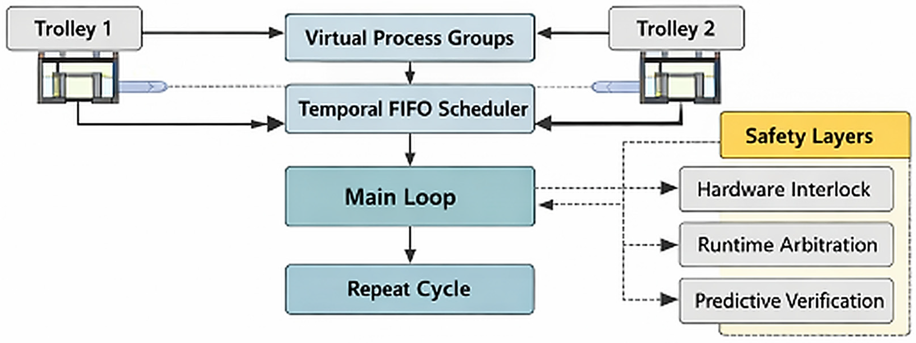
The grouped-resource concept is illustrated in
Figure 2.
This runtime allocation layer is one of the key distinctions of the controller. It converts redundant plant capacity into usable process flexibility while keeping assignment decisions inside the deterministic embedded runtime.
3.5. Temporal FIFO Retrieval Logic
Grouped-bath allocation introduces a second control problem: retrieval cannot be governed by static bath index or simple order of entry once equivalent stations are used dynamically. The controller resolves this through temporal FIFO, whereby retrieval follows process-completion readiness rather than naive insertion order.
For each active grouped bath
, let
denote the completion or readiness time of the currently processed batch. For a grouped resource set
, the retrieval target is selected as
where
denotes the subset of grouped baths whose process has completed and which are eligible for unloading.
This rule means that the controller retrieves the oldest ready batch, not simply the first bath occupied in the group. That distinction is crucial in electroplating control because process validity depends on dwell completion. The grouped-resource logic therefore remains compatible with electrochemical correctness: flexible assignment is allowed during entry, but retrieval is constrained by actual process completion.
Temporal FIFO is not a secondary queue-management detail. It is the mechanism that makes grouped-bath flexibility compatible with deterministic process integrity.
3.6. Safety Model and Operational Invariants
Safety is treated as a structural property of the controller. The line combines shared trolley motion, vertical lifting, heated baths, chemical exposure, and operator-accessible industrial space. Under such conditions, safe operation cannot depend on one protective layer alone. The controller therefore combines predictive validation, runtime software arbitration, and hardware-wired fail-safe interruption.
At the model level, the safety structure can be expressed through the following operational invariants:
conflicting shared-track occupancy is not permitted;
drum lowering is not permitted into an occupied or invalid bath;
process execution is valid only at the correct station-aligned position;
critical faults must remain stoppable through hardware;
grouped-bath retrieval is valid only after process completion.
These invariants are summarized in
Table 3.
These invariants define the controller more precisely than a simple emergency-stop philosophy. Safety is distributed across three coordinated layers:
predictive rejection of unsafe execution plans;
runtime blocking of unsafe motion or process actions;
hardware enforcement of fail-safe interruption under critical conditions.
This layered structure is one of the defining properties of the architecture. It preserves adaptability without relaxing industrial safety.
4. Hardware Architecture and Electronic Implementation
4.1. Controller Platform and Overall Hardware Architecture
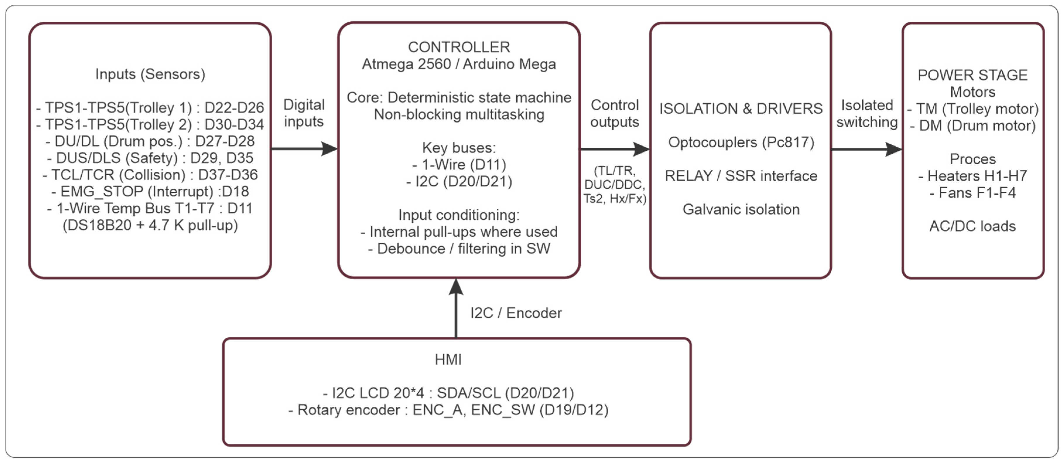
The control system is implemented as a modular embedded architecture centered on the ATmega2560 microcontroller, deployed on an Arduino Mega 2560-compatible platform (Microchip Technology Inc., Chandler, AZ, USA). The selected controller integrates shared-track trolley coordination, grouped-resource handling, local sensing, thermal supervision, and fail-safe control within one deterministic embedded runtime. This choice is central to the work because it shows that adaptive electroplating control can be realized on a compact plant-side platform without a heavier PLC–SCADA or RTOS-based structure.
The hardware is organized into three coupled subsystems: the input acquisition layer, the output and power-interface layer, and the local human–machine interface layer. The input layer collects station-referenced trolley positioning signals, drum-state confirmation, bath-occupancy information, safety-boundary states, emergency-stop status, and distributed temperature measurements. The output layer governs trolley travel, drum lifting and lowering, heater switching, and fan control through isolated relay or contactor interfaces. The HMI layer provides local visibility of trolley and bath states together with cabinet-level parameter adjustment.
This organization reflects the control philosophy of the system. Sensing, actuation, and local diagnostics are physically separated, but they remain logically integrated by the same embedded controller. The resulting architecture is shown in
Figure 3.
The main electronic elements used in the controller are listed in
Table 4.
4.2. Positioning Subsystem
The positioning subsystem provides discrete station-referenced trolley localization. This is one of the defining hardware features of the controller because it avoids dependence on cumulative continuous position estimation in a corrosive and electromagnetically noisy electroplating environment. Instead of relying on trajectory reconstruction, the controller determines trolley position from digital sensor states directly associated with workstation geometry.
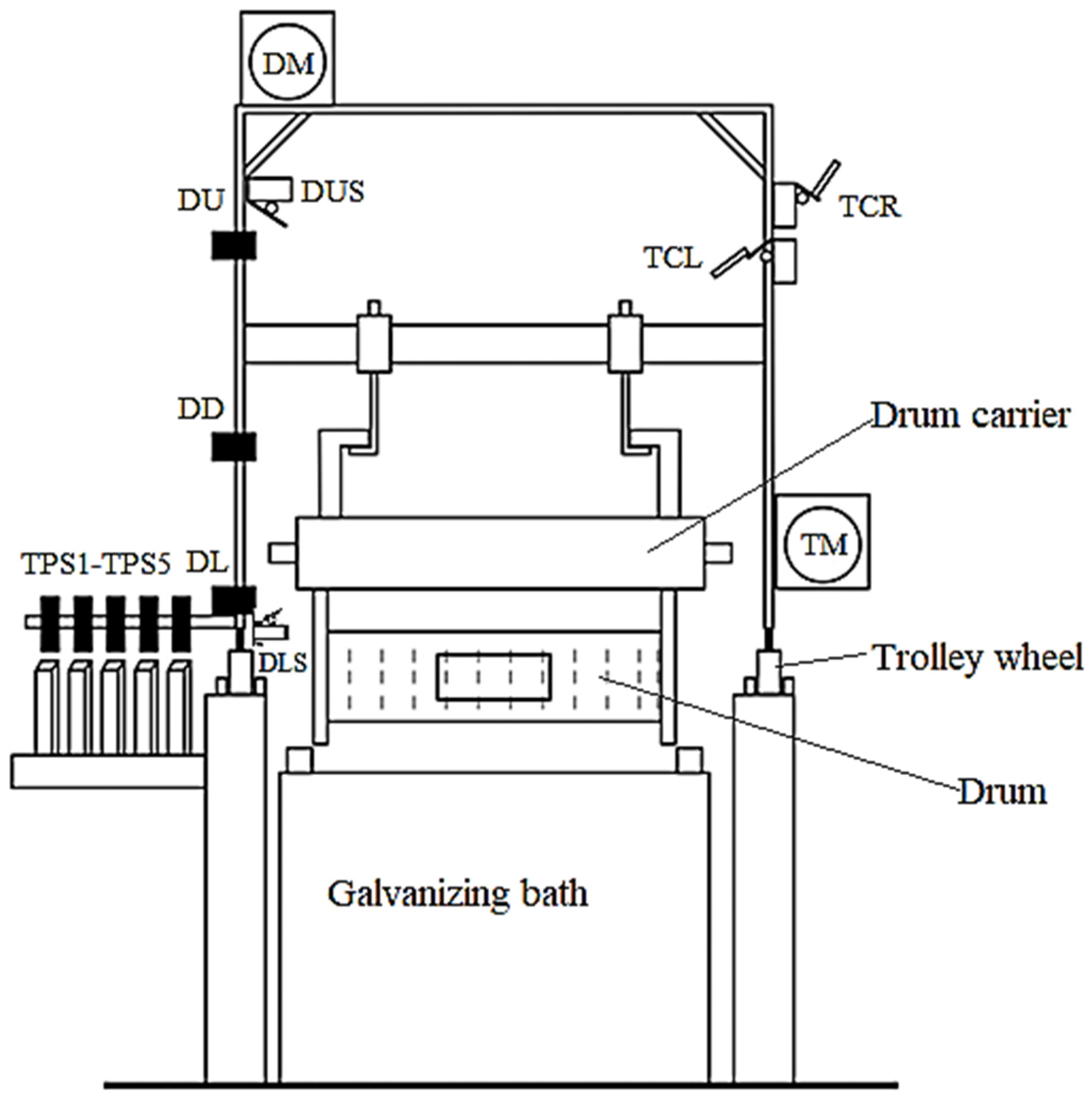
An overview of the trolley sensing and actuation arrangement is shown in
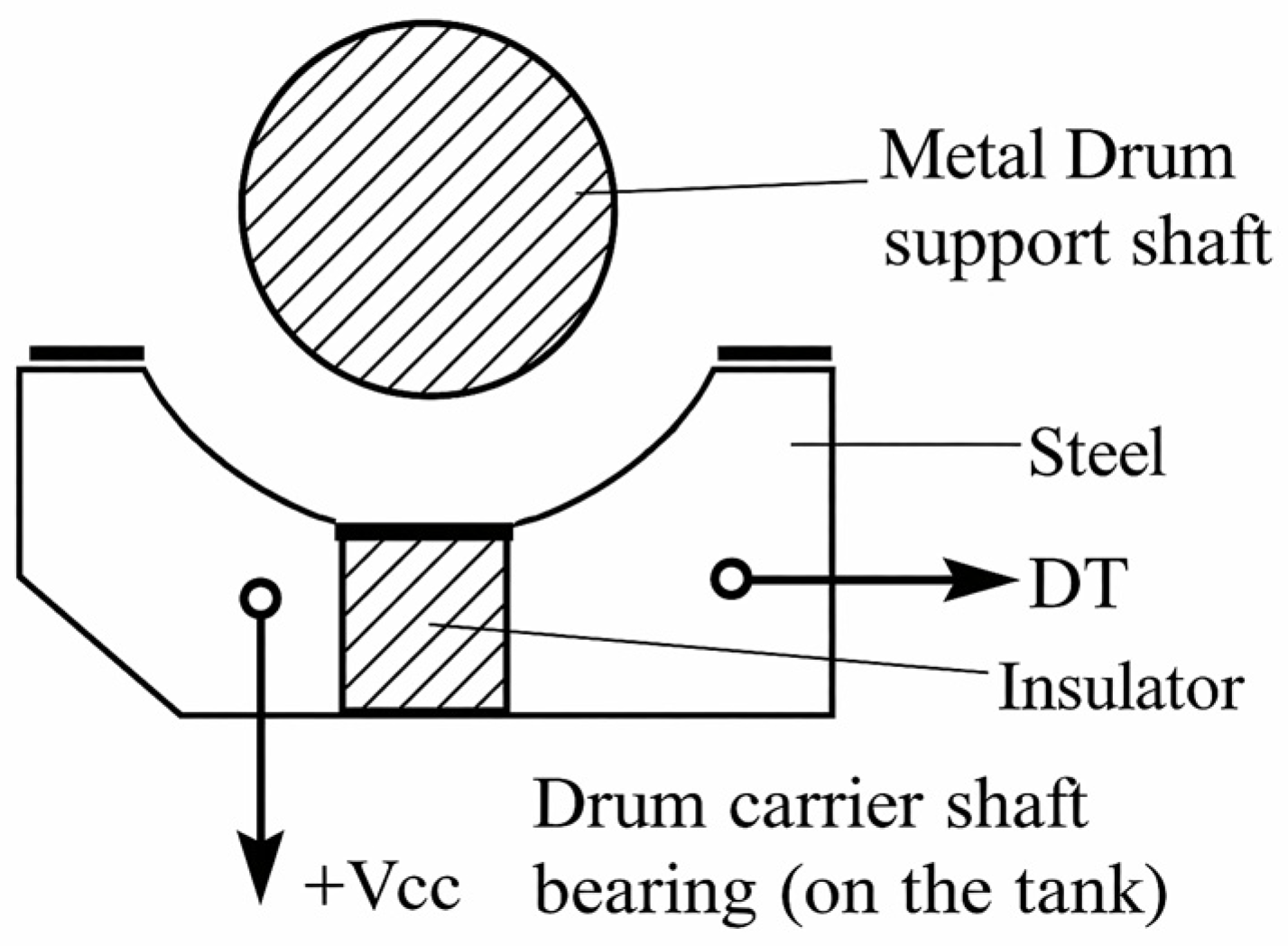
Figure 4, while the mechanical interface between the drum carrier shaft and the bath structure is shown in
Figure 5.
The trolley position along the line is encoded through five binary-coded signals, denoted TPS1–TPS5, which identify the station-centered position above each bath. In the implemented mapping, pins D22–D26 serve the TPS inputs of trolley 1, while pins D30–D34 serve the corresponding inputs of trolley 2. This creates a discrete coordinate system directly compatible with the finite-state execution and dispatcher logic described in
Section 3 and
Section 5.
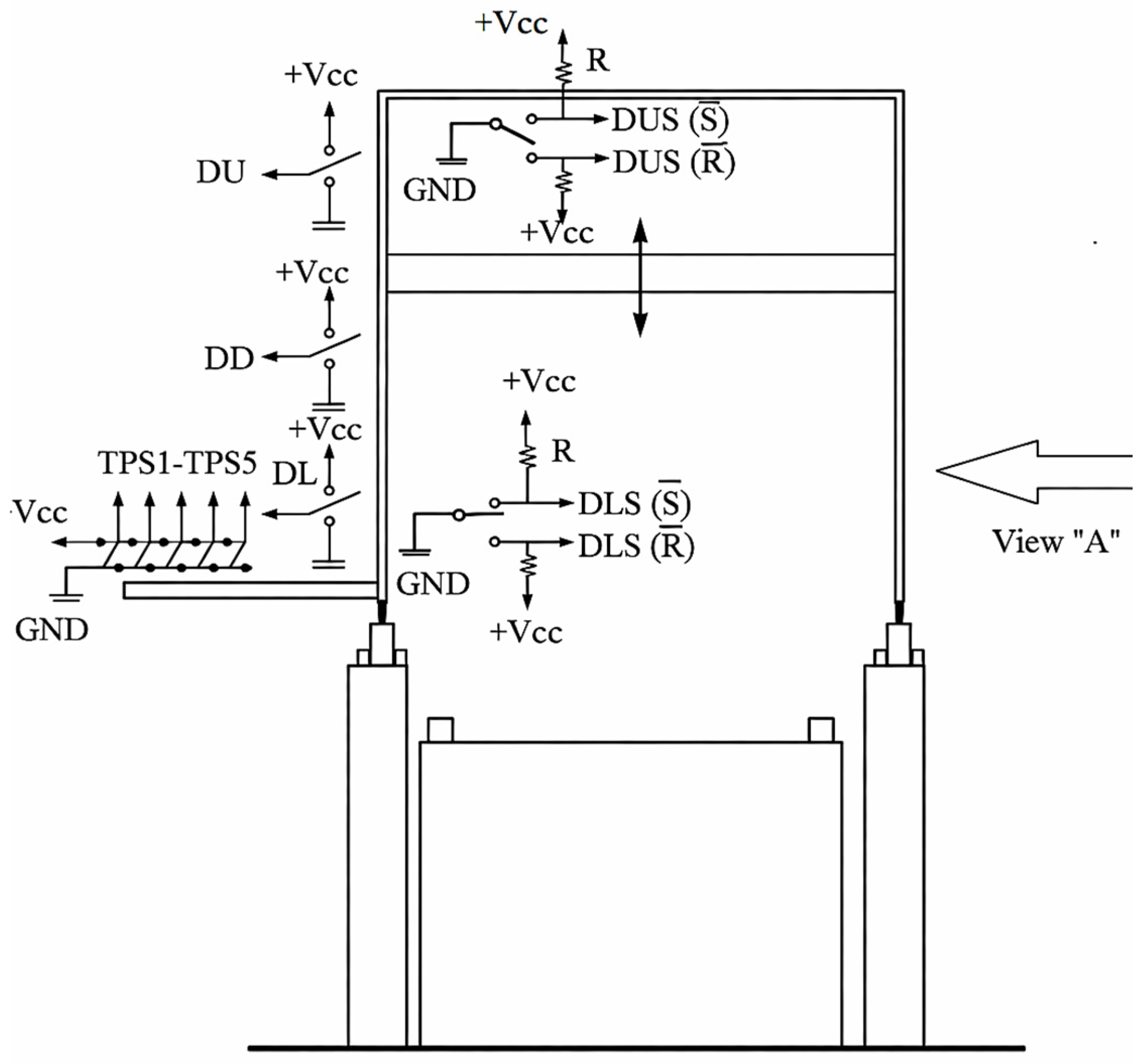
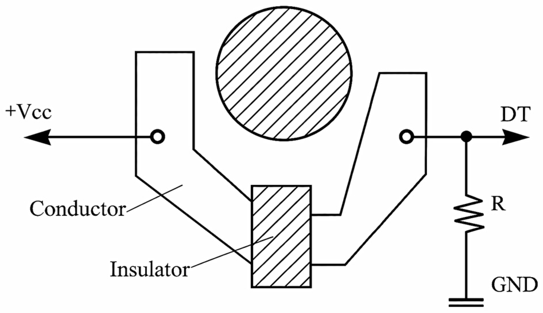
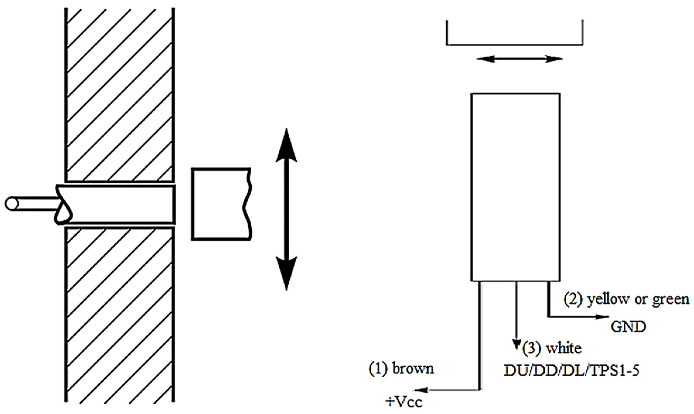
The primary field sensors are industrial inductive proximity sensors functionally equivalent to the Pepperl + Fuchs NBB10-30GM50 family (Pepperl + Fuchs SE, Mannheim, Germany). These sensors are used for trolley and drum state detection, including DU, DL, DT, and the binary-coded TPS signals. Their mechanical robustness and environmental resistance make them appropriate for humid and chemically aggressive plant-side deployment. Their placement and electrical interfacing principle are shown in
Figure 9.
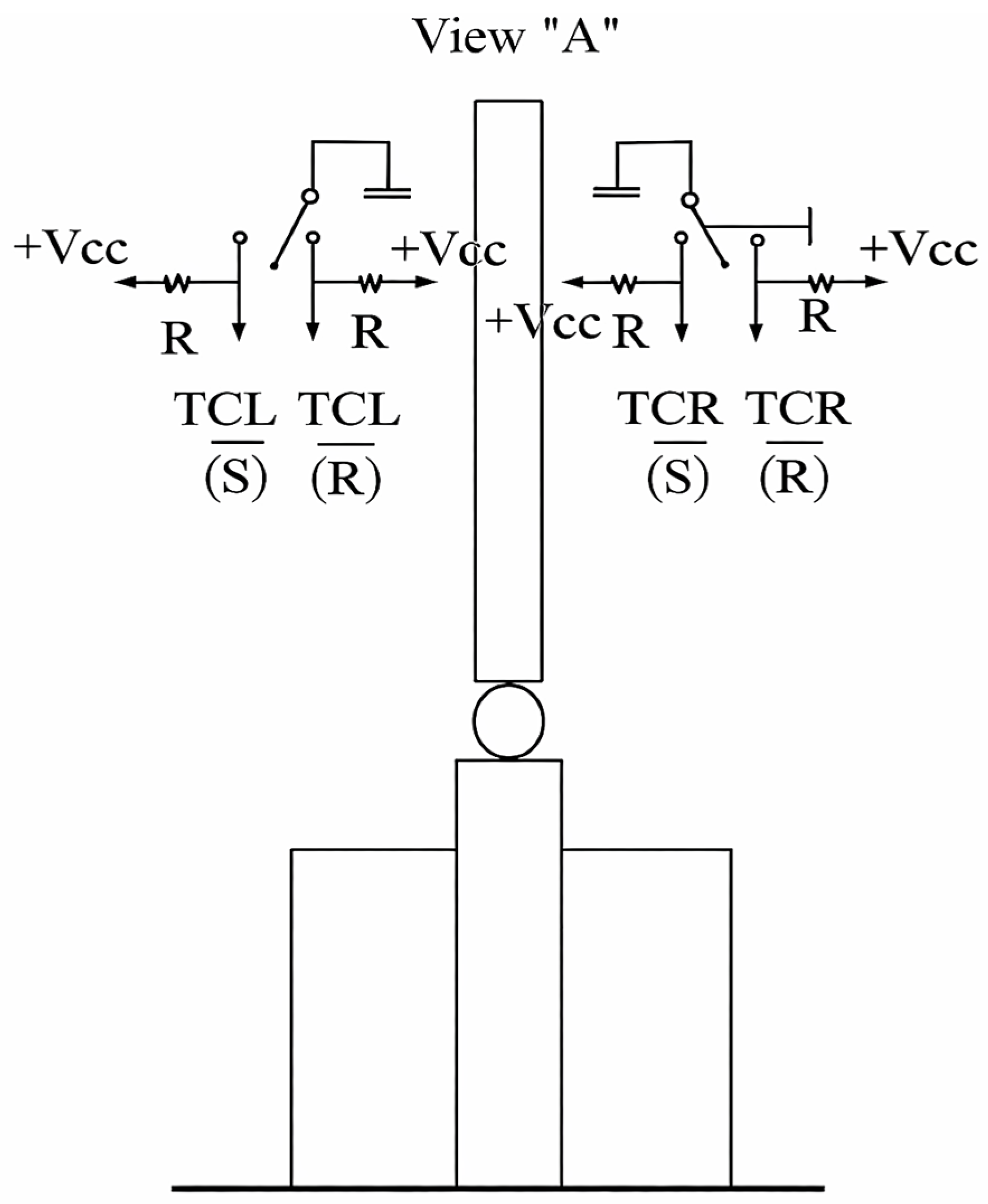
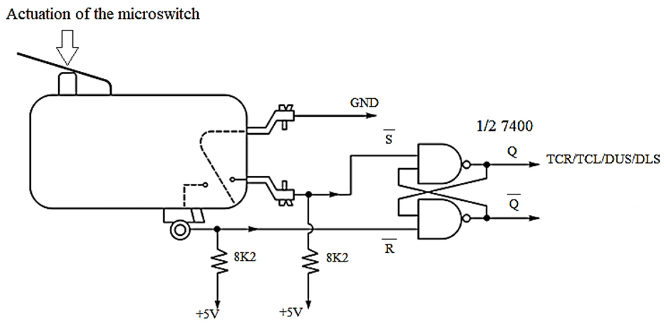
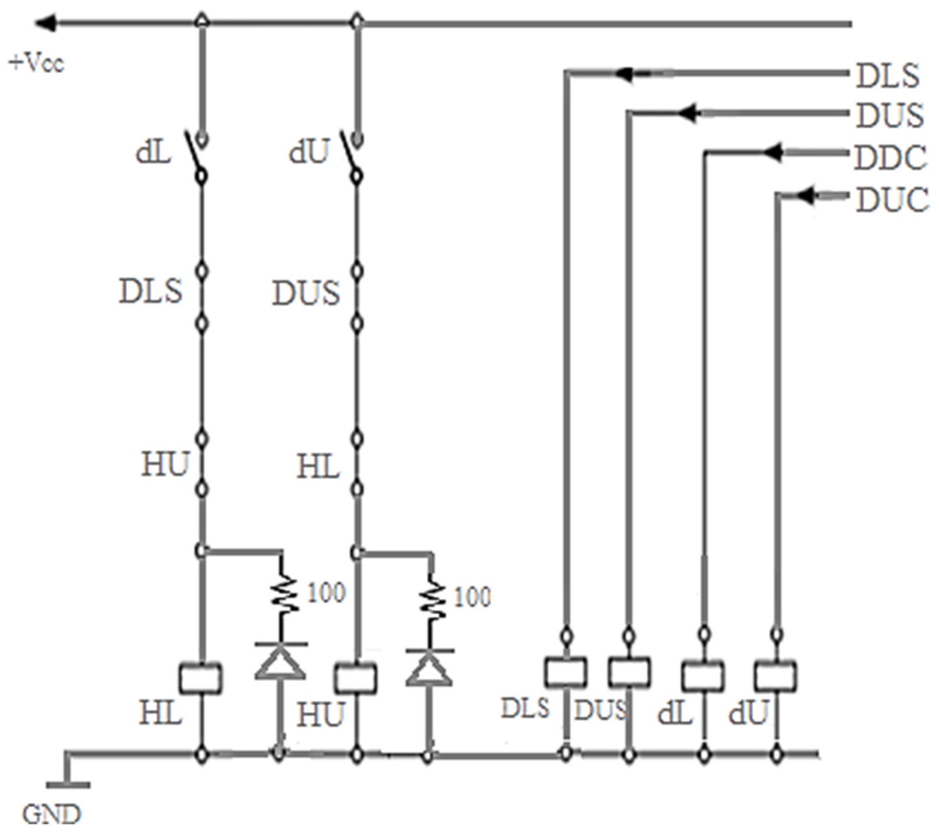
The positioning subsystem is reinforced by mechanical safety switches assigned to DUS, DLS, TCR, and TCL. These signals provide upper and lower drum safety confirmation together with trolley boundary or collision-related constraints. They serve as an independent secondary sensing layer and remain important even when primary inductive sensing is present. Their interfacing principle is shown in
Figure 10.
A distinctive feature of the system is the DT (drum in tank) detection mechanism. Instead of requiring a dedicated immersion sensor at each bath, the controller uses the conductive interaction between the V-shaped drum carrier shaft and the bath structure itself to generate a deterministic immersion and occupancy signal. This reduces the exposed sensor count in the most chemically aggressive part of the plant and provides a direct trigger for process-timer activation.
4.3. Actuation Subsystem
The actuation subsystem converts controller outputs into industrial motion and process actions. It governs horizontal trolley motion, vertical drum movement, speed-stage selection, and the switching of the relay and contactor paths associated with these actions. In the implemented system, trolley transport is performed by two-speed squirrel-cage asynchronous motors with electromagnetic braking, while drum lifting and lowering are handled by a dedicated vertical drive mechanism.
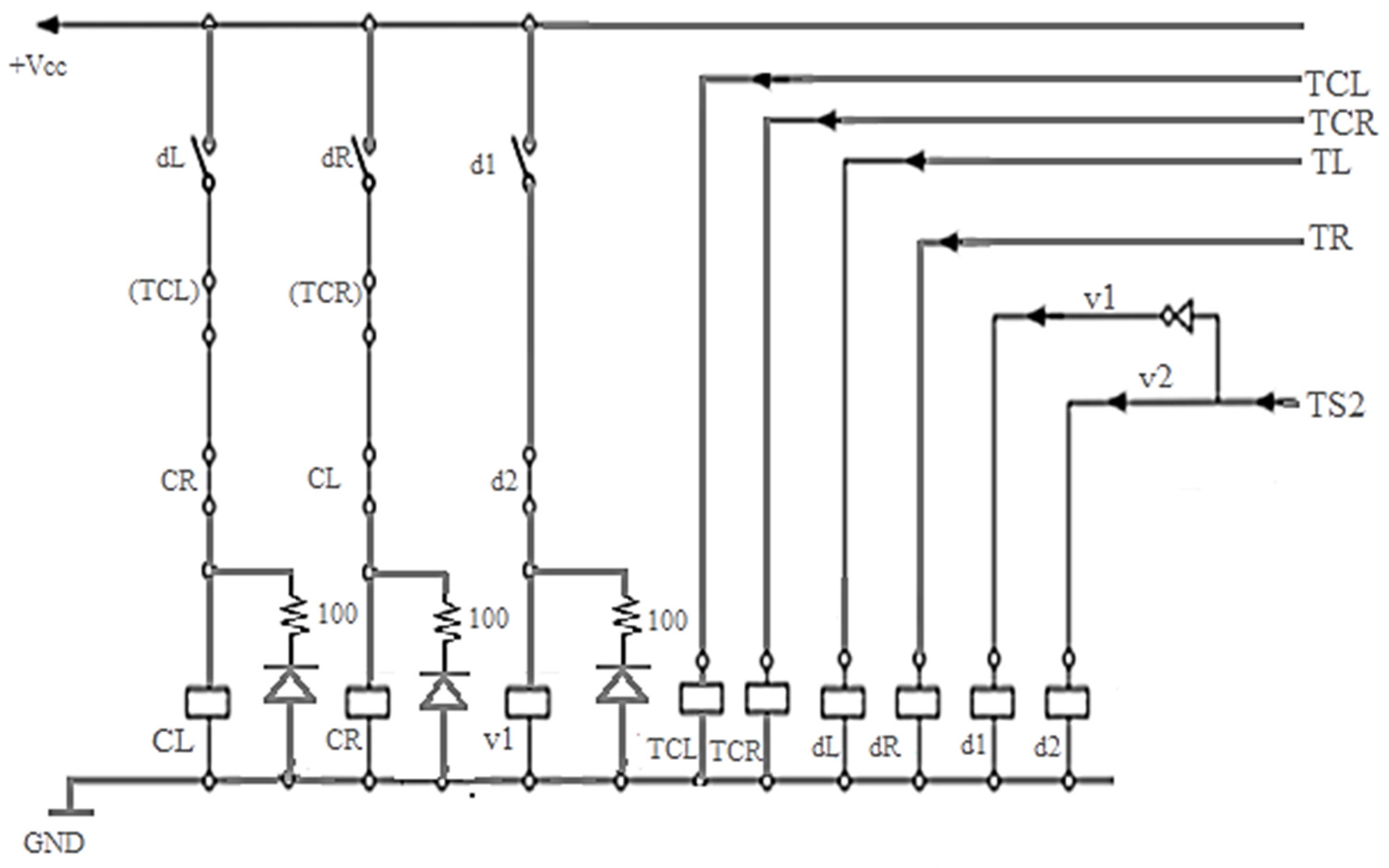
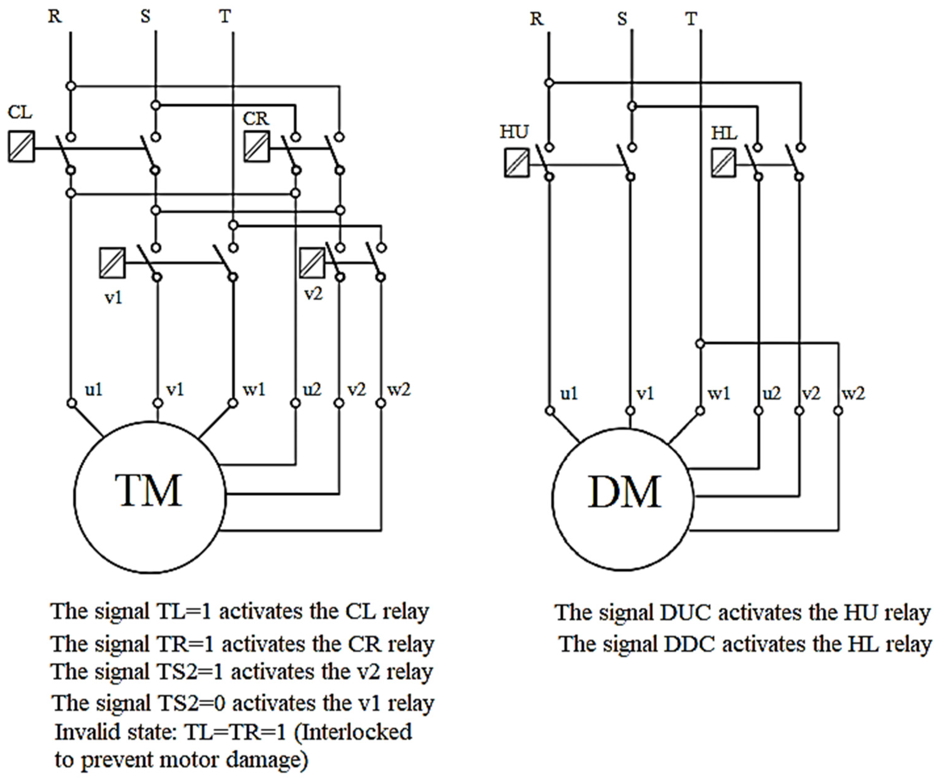
The main functional relation between controller outputs and motion commands is shown in
Figure 11.
Horizontal movement is governed by TL and TR command channels, while vertical drum movement is governed by DUC and DDC. A separate TS2 signal enables the higher trolley speed stage. The motion concept uses lower speed for controlled start and target approach, while higher speed is applied during the intermediate segment of travel. The nominal values specified for the system are 20 cm/s for low-speed travel and 40 cm/s for high-speed travel.
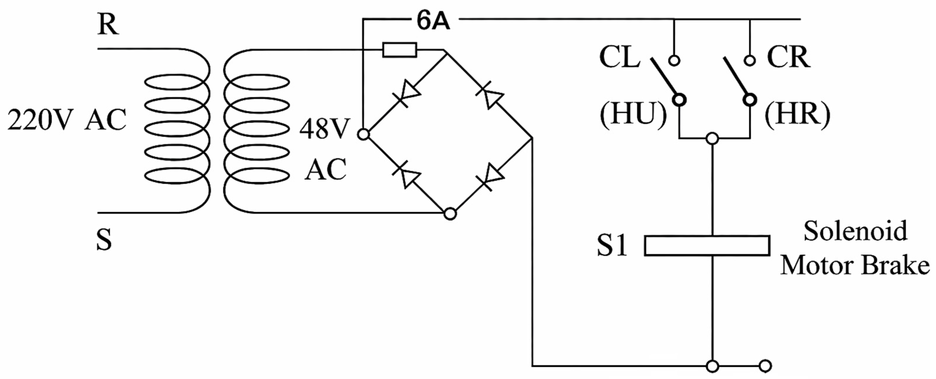
The brake-control arrangement is shown in
Figure 12.
The current paths associated with trolley and drum actuation are shown in
Figure 13 and
Figure 14.
These actuation paths are hardware-interlocked through auxiliary relay contacts so that physically contradictory motion commands cannot be energized simultaneously. This is important because it moves part of the motion-safety burden from software to the power interface itself, which is consistent with the layered protection model adopted throughout the controller.
4.4. Thermal Regulation and Distributed Sensing
The validated electroplating line includes process stages whose electrochemical correctness depends directly on bath temperature. The controller therefore includes distributed digital temperature measurement together with local heater and fan actuation. In the implemented process configuration, the thermal targets are 60 °C ± 1 °C for degreasing, 30 °C ± 1 °C for passivation stations, and 20 °C ± 1 °C for grouped zinc-plating stations.
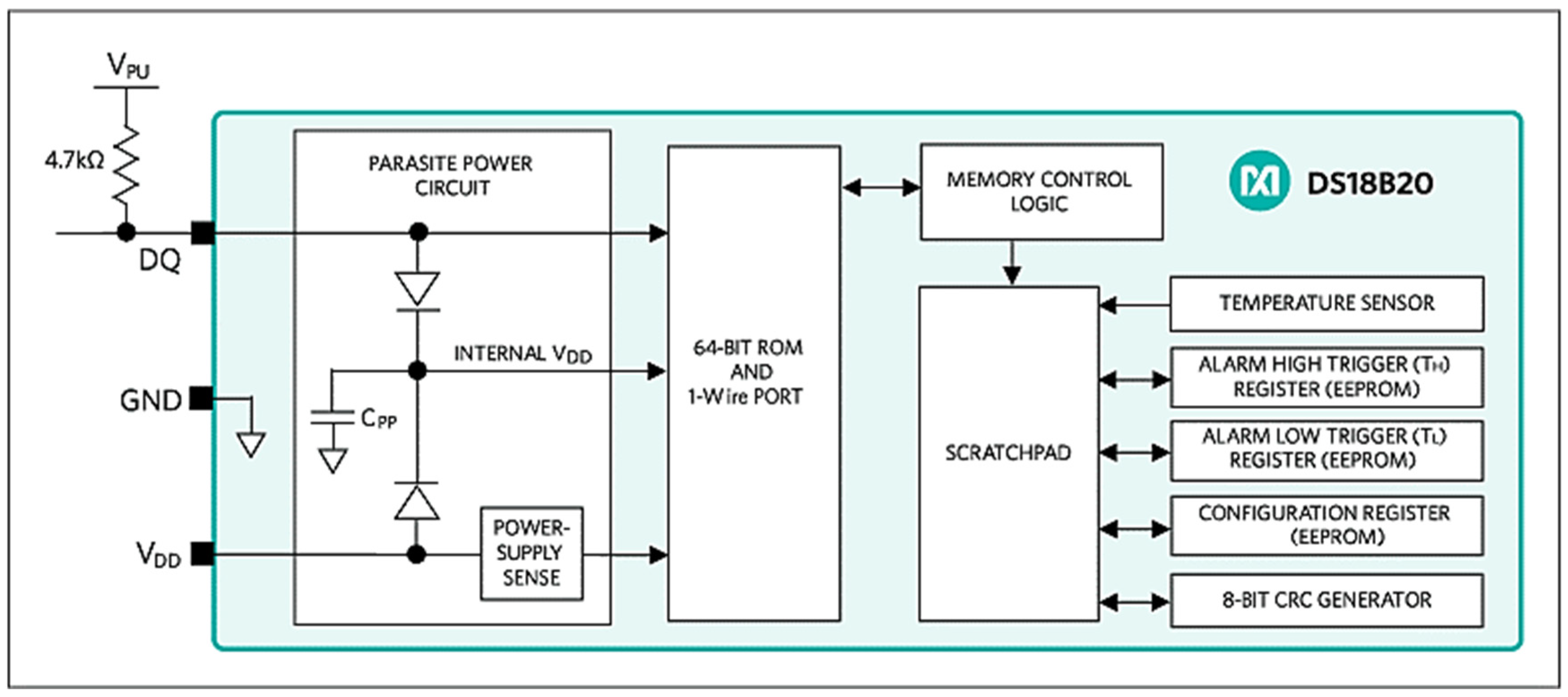
Temperature acquisition is based on the DS18B20 digital temperature sensor (Analog Devices/Maxim Integrated, San Jose, CA, USA). This device is suitable for the present controller because it combines digital output, unique device addressing, and 1-Wire communication, allowing multiple sensors to share one bus without an analog front-end. In the implemented system, seven DS18B20 sensors are connected to a common 1-Wire line through pin D11 using a 4.7 kΩ pull-up resistor. This reduces wiring complexity while preserving station-specific thermal visibility. The DS18B20 structure is shown in
Figure 15.
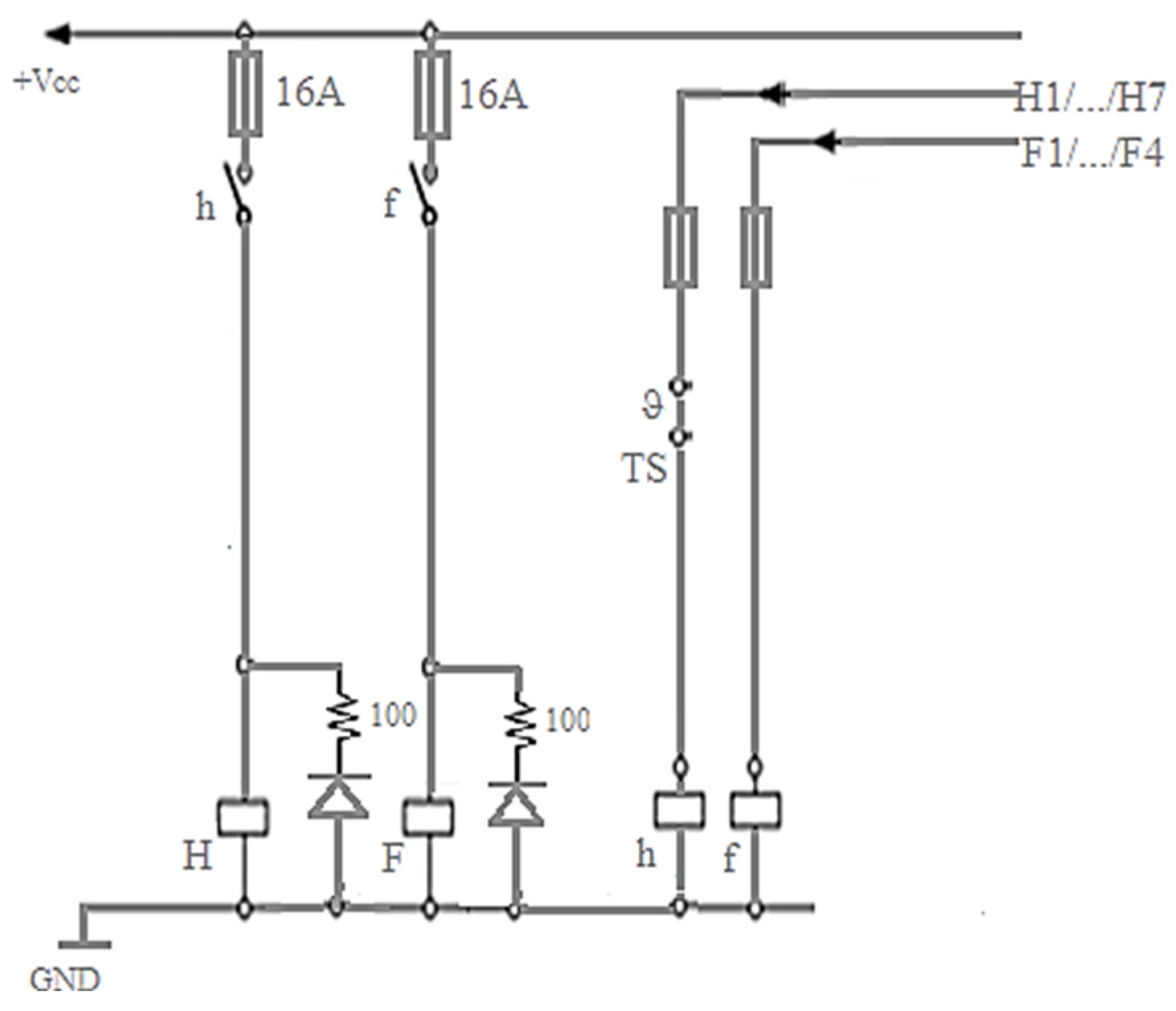
The power-side arrangement for heaters and ventilation fans is shown in
Figure 16.
The thermal subsystem controls seven heater outputs and four fan outputs through relay-based switching. Each bath branch is additionally protected by a fuse and a normally closed thermostatic cutoff placed in series with the heating path. This ensures that thermal safety is not software-only: if the control path or temperature-sensing logic fails, the heating branch can still be interrupted physically at the bath level.
4.5. Human–Machine Interface and Local Diagnostics
The controller includes a compact local human–machine interface intended for cabinet-level diagnostics and parameter adjustment. This interface allows the operator to observe trolley positions, active controller states, and bath temperatures without requiring an external supervisory workstation.
The HMI consists of a 20 × 4 I2C LCD module and a rotary encoder with integrated push-button. The display uses pins D20 and D21 as SDA and SCL lines, while the local menu interaction uses D19 and D12 for encoder-related input. This organization preserves most controller pins for plant-side sensing and actuation while providing sufficient interface bandwidth for local configuration.
The HMI supports real-time display of trolley position, execution state, and temperature data, together with modification of selected technological timing parameters stored in non-volatile memory. This is important for process maintenance because it allows controlled adjustment without firmware recompilation.
4.6. Electrical Protection, Galvanic Isolation, and EMC-Oriented Design
Electroplating plants expose the controller to switching transients, relay-induced disturbances, conductive humidity, and persistent electromagnetic noise. For this reason, electrical separation between low-voltage logic and field-level actuation is a structural requirement of the hardware architecture rather than an optional improvement.
The controller uses PC817 optocouplers (Sharp Corporation, Sakai, Japan) to isolate logic-level outputs from relay, solid-state relay, and contactor interface stages. Motion commands, heater commands, and related process outputs are therefore routed through isolated stages rather than driving field devices directly. This reduces disturbance back-coupling into the ATmega2560 domain and improves runtime stability under industrial switching conditions.
Protection is layered across the hardware. Motion boundaries are reinforced through mechanical safety switches, opposite travel directions are interlocked in the actuation layer, bath heating is protected by thermostatic cutoff, and the emergency-stop signal is wired as a dedicated critical-stop path. These measures are directly aligned with the layered safety structure of the controller.
4.7. Final Pin Mapping and Signal Assignment
The controller input and output assignments are summarized in
Table 5 and
Table 6. These tables define the authoritative hardware reference to which the firmware is aligned.
These mappings define the hardware truth of the controller and form the direct basis for the firmware organization described in the next section.
5. Firmware Architecture and Control Algorithm
5.1. Main Execution Loop and Software Layering
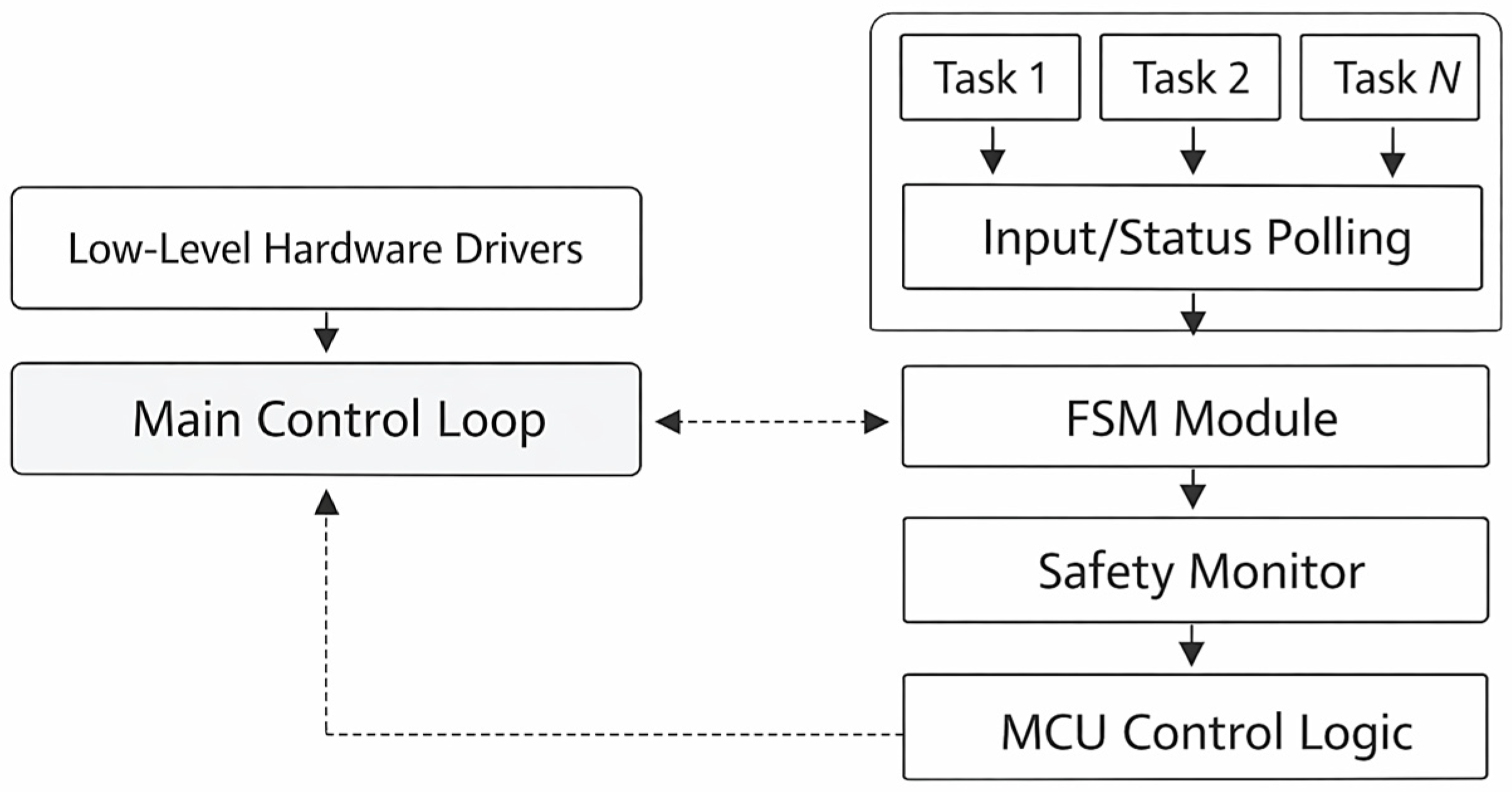
The controller firmware is organized as a deterministic cyclic runtime in which all control functions are evaluated repeatedly inside the main execution loop. This structure is fundamental to the proposed architecture because it enables shared-track trolley coordination, grouped-bath handling, thermal supervision, and safety enforcement within one embedded controller without introducing blocking sequence logic or operating-system overhead.
The runtime is built around five tightly coupled functional layers: hardware initialization and parameter loading, trolley-state evaluation, grouped-resource resolution, process and temperature supervision, and safety/HMI servicing. These layers are not executed as separate threads. They are serviced cooperatively inside the same cyclic control structure, which preserves timing transparency and implementation simplicity on the ATmega2560 microcontroller.
The overall firmware organization is shown in
Figure 17.
During each cycle, the controller updates safety-critical inputs, evaluates trolley agent , evaluates trolley agent , updates grouped-bath readiness and process timers, services the thermal control task, updates the local HMI state, and repeats the loop. The resulting execution model is asynchronous at trolley level and deterministic at controller level. This combination is one of the key properties of the system: both transport agents progress independently, but their decisions remain embedded in one shared safety- and process-aware control structure.
5.2. Independent Trolley Agents and FSM Phase Transitions
Each trolley is implemented as an independent finite-state agent. The controller maintains separate taskPointer, phase, position, assignment, and process-state variables for trolley 1 and trolley 2. This separation eliminates the need for globally blocking sequence progression and allows one trolley to continue productive motion while the other remains in a dwell-constrained process state.
The state machine used by the controller is summarized in
Table 7.
The Dynamic Homing phase establishes a valid positional reference at startup. This is essential because all subsequent routing, grouped-bath allocation, and safety decisions depend on correct station-referenced localization. The Target Dispatching phase translates the next encoded process command into a concrete physical target. The Motion Left and Motion Right phases execute horizontal travel until the assigned station is reached. The Process Cycle phase governs lowering, immersion confirmation, dwell timing, and lifting. The Idle/End phase provides a deterministic safe state when a sequence is completed or not active.
This FSM structure is central to the controller because it turns electroplating execution into a state-consistent embedded process rather than a relay-like step cascade. The measured reduction in trolley idle time reported later in the paper follows directly from this local state progression model.
5.3. Dispatcher Logic for Virtual Process Groups
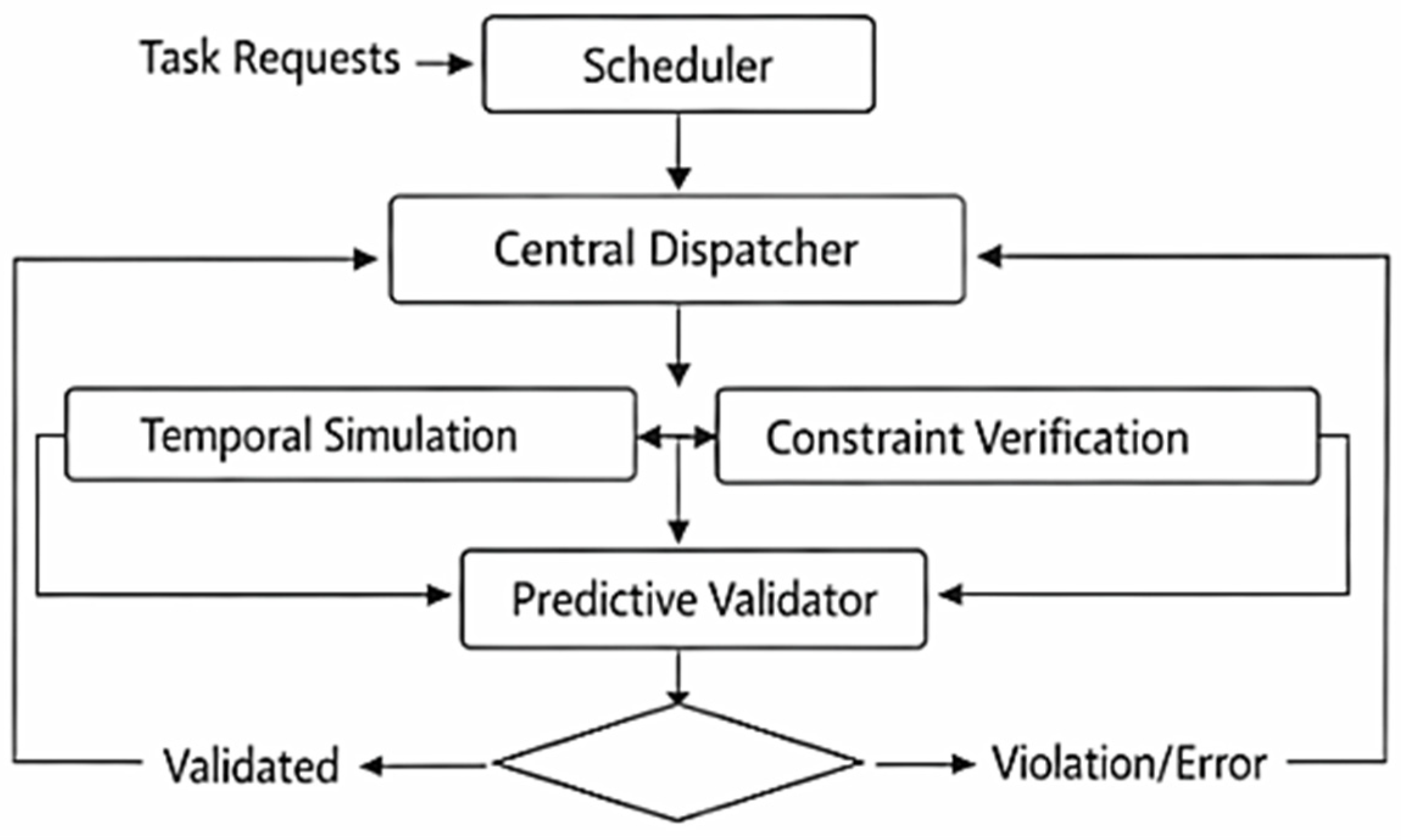
Redundant process baths are handled through a dispatcher layer that resolves virtual process groups into actual physical destinations at runtime. In the recipe structure, some commands refer to fixed stations, while others refer to grouped process resources. The dispatcher converts a grouped-resource request into a physically executable station assignment under current occupancy and safety conditions.
For a grouped process request , the controller evaluates the candidate baths associated with that group and assigns one physical bath according to three conditions: the bath is free, the bath belongs to the required technological group, and the motion required to reach it is admissible under current shared-track constraints. This keeps grouped-resource logic inside the controller rather than delegating it to an external scheduler.
The dispatcher workflow is shown in
Figure 18.
Once the dispatcher selects a bath, the assignment is stored in the trolley-local runtime state. From that point onward, the trolley no longer acts on the abstract group identifier, but on a resolved physical destination. This mechanism is the plant-side executable form of grouped-resource allocation. Its role is not auxiliary. It is one of the main reasons the controller can exploit redundant zinc-plating and passivation baths without collapsing into rigid fixed-address execution.
5.4. Temporal FIFO Completion and Retrieval Logic
Grouped-bath assignment requires a retrieval rule that preserves process validity. When several equivalent baths are used dynamically, retrieval cannot follow static bath index or simple insertion order. The controller resolves this through temporal FIFO, whereby grouped-bath unloading is governed by process-completion readiness.
The controller maintains a completion or readiness time for each active grouped bath. Retrieval from a grouped set is then resolved by selecting the bath whose completed batch is chronologically oldest among the ready candidates. This keeps grouped-resource use compatible with dwell-time integrity. The controller therefore retrieves the oldest ready batch, not the bath that was occupied first.
This distinction is essential in electroplating control because process validity depends on dwell completion rather than station order. Runtime flexibility is achieved without shortening the electrochemical process or introducing arbitrary retrieval behavior.
5.5. Predictive Verification Before Motion or Process Start
The controller includes a pre-execution predictive validation layer that evaluates the admissibility of technological command sequences before mechanical execution starts. This layer is especially important in a shared-track dual-trolley system because unsafe sequence combinations can be rejected before the plant enters a hazardous state.
The predictive model uses station-referenced travel estimation and configured process durations. Let
denote the average travel time between adjacent stations,
the dwell duration of the active process step, and
the minimum admissible trolley spacing in station units. The estimated completion time of a candidate transition is expressed as
The controller evaluates virtual trolley progression using these timing assumptions and checks whether future shared-track conflicts or grouped-resource violations can arise. A conflict condition is represented by
where
is the temporal conflict window and
the minimum allowed station-based spatial separation.
This layer does not serve as a global optimizer. Its function is narrower and more practical: it acts as an admissibility filter between stored recipes and physical execution. In a grouped-resource electroplating line, that role is crucial because grouped bath requests may map to more than one admissible station. The predictive layer prevents unsafe execution plans from reaching the motion stage.
5.6. Hardware–Software Safety Integration
The controller uses a layered safety strategy in which predictive verification, runtime software arbitration, and hardware-wired interruption operate together. This arrangement is necessary because electroplating automation combines shared trolley motion, vertical drum handling, heated baths, and operator-accessible industrial space.
At runtime, the software layer supervises unsafe trolley proximity, invalid bath states, inadmissible lowering conditions, and critical-stop inputs. If a conflict is detected, motion or process execution is blocked before the corresponding output is issued. This gives the controller an active runtime safety role rather than a passive monitoring role.
The hardware layer remains independent of ordinary state progression. Emergency stop, direction-blocking contact arrangements, thermostatic cutoffs, and normally closed interlocks remain capable of interrupting unsafe behavior even if software state progression becomes invalid. This is a defining feature of the architecture. Safety is not reduced to software correctness; it is distributed across predictive, software, and hardware layers.
5.7. Thermal Control Task
The firmware also includes a non-blocking thermal regulation task for maintaining the prescribed operating temperatures of the selected baths. This task is integrated into the same cyclic runtime structure used for motion and process control, which is important because thermal supervision must not degrade trolley responsiveness or safety reaction time.
The thermal routine acquires measurements from the distributed DS18B20 digital temperature sensor network, compares them with the configured setpoints, and actuates heater and fan outputs accordingly. Its functional role is fourfold: acquisition of bath-specific temperatures, comparison with thermal thresholds, actuation of heaters or fans, and detection of implausible thermal states that require safe response.
This layer confirms that the controller is not merely a transport sequencer. It is a unified electroplating controller in which trolley coordination, grouped-bath handling, dwell-time preservation, safety, and process supervision are executed inside the same deterministic embedded runtime.
6. Implementation Details and Code-Level Consistency
6.1. Final Firmware Organization
The scientific value of the proposed controller depends not only on the control model itself, but also on the degree to which the described architecture is traceable to an unambiguous executable implementation. This requirement is especially important in compact industrial embedded systems, where small inconsistencies in I/O mapping, state progression, grouped-resource logic, or safety handling can alter runtime behavior substantially. The controller associated with this work was therefore consolidated into one authoritative firmware structure aligned with the hardware definitions of
Section 4 and the control principles of
Section 5.
The final supplementary implementation is organized around one main runtime controller and one validation-oriented companion module. The main controller contains the executable plant-side logic for shared-track trolley coordination, station reconstruction from binary TPS inputs, compact process-step decoding, grouped-bath assignment, drum-cycle handling, thermal regulation, HMI servicing, and emergency-stop supervision. The validation-oriented module reconstructs the controller-level comparative trends discussed later in the manuscript through a transparent scenario companion that implements grouped-resource allocation, temporal FIFO retrieval, degraded grouped-bath continuity, and predictive recipe admissibility checking. This separation is necessary because the architecture described in this paper must correspond to one controller, not to multiple partially overlapping development variants.
At execution level, the final firmware preserves the same architectural decomposition introduced in the manuscript. Trolley progression is asynchronous and phase-driven, grouped resources are resolved before motion execution, process readiness is tracked independently of trolley position, thermal regulation is serviced in the background, and safety remains distributed across predictive, software, and hardware layers. The code therefore acts as the direct executable form of the control model rather than as a loosely related engineering artifact.
6.2. Mapping Between Manuscript Logic and Firmware Functions
The relationship between the manuscript-level concepts and the executable controller is summarized through explicit mapping of functional modules to their corresponding implementation routines. This mapping is important because the contribution of this paper lies in the fact that the core control mechanisms—shared-track asynchronous execution, grouped-resource allocation, temporal FIFO retrieval, and layered safety—exist both as formal control ideas and as implemented controller behavior.
The concept of asynchronous trolley execution is realized through the trolley-specific runtime routine, which maintains independent taskPointer, phase, assignment, and readiness variables for each trolley. The concept of station-referenced localization is implemented through the TPS decoding logic, which reconstructs station-aligned position from binary digital inputs. The concept of recipe-driven control is implemented through the task-loading routine, which interprets the encoded process step and resolves whether the next command addresses a fixed station or a grouped resource. The concept of drum-cycle execution is implemented through a dedicated process routine that governs lowering, immersion confirmation, dwell timing, lifting, and completion state transition. The concept of virtual process groups is implemented through dispatcher logic that converts grouped process requests into concrete bath assignments under occupancy and safety constraints. The concept of temporal FIFO is implemented through readiness-time comparison over grouped baths. The concept of distributed thermal supervision is implemented through a non-blocking temperature-control routine integrated into the cyclic runtime.
This relationship is summarized in
Table 8.
This table is not intended as a programming appendix. Its purpose is to demonstrate structural consistency: the controller described in the manuscript is the same controller represented in the Supplementary Code in
Supplementary Materials. This type of traceability is particularly relevant in embedded automation research, where scientific novelty loses force if the implementation remains ambiguous or only partially aligned with the narrative architecture.
6.3. Consolidation Changes Introduced in the Final Implementation
The final firmware required targeted consolidation because the development-stage code contained elements that were acceptable during iterative prototyping but unsuitable for a publication-grade supplementary package. Three issues were addressed directly: duplicated logic, hardware–software mismatches, and incomplete grouped-resource lifecycle handling.
The first issue concerned duplicated or partially overlapping implementations of key control routines. During prototyping, multiple variants existed for trolley execution, task loading, position reconstruction, drum-cycle control, and thermal regulation. The final implementation replaces these parallel development traces with one authoritative routine for each role. This correction is necessary because this paper describes one controller architecture, not a family of related prototypes.
The second issue concerned hardware–software alignment. The final controller must conform exactly to the input and output assignments defined in
Table 5 and
Table 6. This was particularly important in the HMI and critical-safety domains. Display communication remains isolated on the dedicated I2C interface, encoder-related inputs remain separated from that interface, and the emergency-stop signal is treated as a true high-priority stop path. This closes the gap between hardware description and runtime behavior and removes contradictions that would otherwise undermine reproducibility.
The third issue concerned grouped-resource lifecycle closure. Since the controller depends strongly on virtual process groups and temporal FIFO, grouped baths cannot be referenced informally in code. The final implementation therefore maintains explicit runtime state for grouped-bath occupancy, assignment, process readiness, retrieval eligibility, and post-retrieval release. This is a decisive point of consistency. Grouped-resource handling is one of the main scientific contributions of the controller, and the code must represent it as a coherent execution mechanism rather than as a scattered set of conditions.
A similar requirement applies to the thermal subsystem. Since trolley motion, grouped-bath handling, safety supervision, and local HMI operation all share one cyclic runtime, temperature handling must remain non-blocking. The final implementation preserves thermal acquisition and heater/fan actuation as periodic background services. This keeps the firmware aligned with the execution model defined in
Section 5 and avoids contradictions between claimed responsiveness and actual control structure.
The resulting code base is therefore not simply the software used during experimentation. It is the implementation-consistent counterpart of the controller architecture described in the manuscript. Its role in this paper is methodological: it closes the link between model, hardware, runtime behavior, supplementary scenario-based validation, and the reported controller-level results.
7. Experimental Setup and Validation Protocol
7.1. Controller-Centered HIL Testbed
The proposed controller was validated in a controller-centered hardware-in-the-loop environment representing an 18-station zinc electroplating line with two autonomous trolleys operating on a shared linear rail path. The validation platform combined execution of the real plant-side firmware on the target embedded controller with a high-fidelity discrete-event representation of the electroplating line, including station topology, trolley movement, grouped process resources, dwell-time behavior, and safety-relevant event timing. This configuration preserved implementation consistency at controller level while allowing systematic assessment of operating scenarios that would be difficult or unsafe to reproduce directly on an operational industrial asset.
The control hardware corresponded to the same embedded architecture described in the preceding sections: an ATmega2560-based controller with binary-coded trolley positioning, drum-state and bath-occupancy signaling, grouped process resources for zinc plating and passivation, distributed temperature supervision, isolated actuation, and local HMI support. The plant model represented the 18-station electroplating line as a discrete-event process system with two trolleys, fixed and redundant bath locations, process durations, motion timing, and safety-related state changes. The HIL concept also accounted for timing-related abstractions relevant to trolley movement, event-level sensing, and long-horizon execution over 100 consecutive batches.
To make the controller-centered HIL assumptions explicit, the validation model represented trolley motion at station-transition level rather than through a full continuous mechanical drive model. The embedded controller operated on discrete station-referenced semantics, while the HIL environment assigned travel-time equivalents to inter-station movement, incorporated bounded sensor-feedback delay at the event-processing level, and preserved configured dwell durations for each technological step. Long-horizon execution over 100 consecutive batches was evaluated in accelerated time without altering controller logic, state progression, dispatching rules, or safety checks. Accordingly, the HIL framework should be interpreted as an implementation-consistent controller-validation environment with timing-aware execution abstraction, not as a full plant-identification model of all physical drive and sensing dynamics.
This validation structure is methodologically important because it keeps the reported results tied to the actual controller logic and I/O semantics, not to an abstract scheduler detached from implementation. The controller was therefore assessed as an embedded execution system for shared-track electroplating control rather than as a purely mathematical scheduling model.
7.2. Validation Scenarios
The first scenario was the baseline Static Sequential Logic (SSL) mode. This mode was implemented within the same controller-centered validation framework as a reference execution logic with fixed station assignment, non-adaptive use of redundant baths, and rigid sequential trolley progression. SSL therefore serves in this study as a structured baseline architecture for comparison under unchanged line topology, technological recipes, and process assumptions. It should not be interpreted as a full reverse-engineering of every historical legacy implementation detail, but as a reference static control mode designed to isolate the effect of the proposed asynchronous dispatching, grouped-resource allocation, and readiness-based retrieval logic.
The second scenario was the full asynchronous dynamic mode. In this mode, the controller operated with independent trolley agents, runtime grouped-resource assignment, and temporal FIFO retrieval. This was the principal operating mode used to evaluate the core control contribution of the work.
The third scenario addressed shared-track disturbance handling. Artificial delay was introduced into one trolley trajectory in order to test whether runtime arbitration preserved safe trolley separation without forcing complete process interruption.
The fourth scenario addressed degraded grouped-bath operation. In this case, one member of a redundant process group was treated as unavailable, allowing evaluation of whether the controller could continue production through reassignment of the remaining grouped stations.
The fifth scenario addressed predictive recipe validation. Multiple technological command tables were submitted to the pre-start validation layer in order to verify whether unsafe command sequences were rejected before execution.
The complete scenario set is summarized in
Table 9.
This scenario structure matches the controller contribution directly. The system was therefore assessed not only as a transport mechanism, but as an integrated architecture for motion coordination, grouped-resource handling, process validity, and safety.
7.3. Performance Metrics
The selected metrics were chosen to capture both industrial relevance and control-architectural significance.
The primary metric was total makespan, defined as the total completion time required for the evaluated production horizon. This metric was used as the main throughput indicator because it reflects the combined effect of trolley coordination, grouped-bath use, and process waiting.
The second metric was average trolley idle time per batch. This quantity measures the duration during which a trolley is available but not productively engaged in movement or process support. It is particularly important here because one of the controller objectives is the reduction of non-productive waiting introduced by rigid sequential logic.
The third metric was grouped-bath utilization, evaluated primarily for the redundant zinc-plating section. This metric indicates whether the virtual process group mechanism converts physical redundancy into effective runtime process use.
The fourth metric was bottleneck incidence, used to quantify how often one process segment or movement dependency constrained broader line progression.
The fifth metric was safety-related execution correctness, assessed through conflict avoidance, preservation of trolley spacing under disturbed motion, and correct rejection of unsafe technological recipes by the predictive validation layer.
The sixth metric was degraded-mode continuity, expressed through the ability of the controller to continue production after loss of one grouped station together with the associated reduction in nominal capacity.
For extended evaluation, the validation horizon was set to 100 consecutive production batches. In the original HIL framework, long-horizon execution was evaluated in accelerated time, which allowed stable comparison of controller modes without changing the structure of the embedded control logic.
7.4. Validation Workflow and Controller-Oriented Procedure
The validation workflow was designed to preserve a direct link between the reported outcomes and the executable controller.
First, the technological command tables were prepared in the same compact embedded format used by the runtime controller. This ensured that predictive validation, task decoding, grouped-bath assignment, and drum-cycle execution all operated on the same process representation used in actual control logic.
Second, the firmware was executed on the target controller hardware, preserving the same control structure, timing semantics, and state logic described in
Section 4,
Section 5 and
Section 6. The plant-side process behavior was then coupled to the controller through the HIL environment, which reproduced trolley movement, station transitions, grouped-bath occupancy, process-completion timing, and safety-relevant event responses.
Third, the selected scenario was executed within this controller-centered validation framework. For long-horizon assessment, accelerated time interpretation was used so that extended-cycle behavior could be evaluated without changing the embedded control logic itself. This approach preserved the runtime meaning of the controller states while making comparison over 100 batches practical.
Fourth, the resulting controller traces were observed at the level of trolley phase progression, grouped-bath occupancy, readiness state, process completion, and safety-layer response. Special attention was given to the grouped zinc-plating section because it is the main redundant process zone through which the effect of dynamic allocation becomes most visible.
The collected traces were reduced into the defined metrics and compared between two controller modes: Static Sequential Logic as the baseline reference architecture and Asynchronous Dynamic Dispatcher as the proposed architecture. This comparison isolates the effect of the control strategy itself. The station semantics, process structure, and validated line topology remain unchanged; the difference lies in the runtime logic governing trolley independence, grouped-bath allocation, and retrieval readiness.
The protocol therefore evaluates not only productivity, but also process correctness and structural robustness of the controller under implementation-consistent industrial conditions.
8. Results and Discussion
8.1. Throughput and Resource Utilization
The main question of the validation campaign was whether the proposed Asynchronous Dynamic Dispatcher (ADD) architecture provides measurable operational gains over a conventional Static Sequential Logic (SSL) baseline under the same line topology and process assumptions. Over the evaluated horizon of 100 consecutive production batches, the ADD architecture reduced total makespan from 1642 min to 1244 min, corresponding to a 24.2% throughput improvement. This result shows that the gain originates from the control strategy itself, since the physical line, process stations, and trolley hardware remain unchanged.
A similarly strong effect was observed in trolley inactivity. Under SSL, average trolley idle time reached 18.4 min/batch. Under ADD, this value decreased to 4.1 min/batch, corresponding to a 77.7% reduction. This result is important because it shows that the architecture improves productivity mainly by reducing non-productive waiting, not by altering process duration. The control gain is therefore structural: one trolley can continue useful execution while the other remains engaged in a dwell-constrained step.
More specifically, the gain emerges from three interacting architectural effects. First, asynchronous local trolley progression reduces structurally unnecessary waiting that is inherent in rigid globally serialized execution. Second, runtime selection among equivalent grouped baths converts nominal physical redundancy into effective process availability. Third, readiness-based retrieval prevents grouped-resource flexibility from violating dwell-time integrity. The reported makespan reduction should therefore be interpreted as the result of improved execution logic under unchanged plant hardware, not as an effect of shortened electrochemical processing.
The grouped-bath results confirm the same pattern. Utilization of the grouped zinc-plating section increased by 27.0%, from 64% in SSL to 91% in ADD. At the same time, tracked bottleneck incidents decreased from 18 to 2, an 88.9% reduction. These results show that the controller improves not only global throughput but also the internal flow quality of the line by converting redundant bath capacity into effective runtime process capacity. The main quantitative comparison is given in
Table 10.
These results support the central architectural claim of the paper: the main performance benefit of the controller comes from improved runtime coordination of shared-track motion, grouped-resource use, and dwell-constrained execution.
8.2. Temporal FIFO and Dwell-Time Integrity
Runtime allocation of grouped baths is only valid if retrieval remains technologically correct. The experimental observations confirmed that retrieval from grouped stations followed process-completion readiness rather than static order of entry. This behavior validates the role of temporal FIFO as a process-integrity mechanism rather than a simple queueing rule.
This result was especially important in non-linear grouped-bath cases, where drums entered different zinc-plating baths under asymmetric availability conditions. Retrieval did not follow bath index or insertion order. It followed the completion state of the active batch in each grouped bath. This confirms that the controller decouples bath identity from dwell-time validity, which is one of the core control ideas of the work.
The throughput improvement reported in
Section 8.1 must therefore be interpreted carefully. The controller does not increase productivity by shortening the electrochemical process. It increases productivity by reducing non-productive waiting and by using redundant grouped baths more effectively while preserving process-completion-based retrieval.
8.3. Safety Validation and Conflict Prevention
The safety-related results confirm that the three-layer protection concept operates coherently at controller level. The pre-start validation layer was assessed using 50 technological recipes, including intentionally inconsistent command structures. Within this evaluated set, the controller successfully identified all introduced logical conflicts, including infeasible trolley trajectories and overlapping shared-track occupancy in the same time window. The validation of a 45 min plating cycle was completed in 138 ms on the ATmega2560 platform, indicating that predictive admissibility checking introduces negligible practical delay relative to industrial process duration.
Runtime robustness was examined through disturbed-motion scenarios in which an artificial delay was introduced into one trolley trajectory. Under these conditions, the controller correctly paused the trailing trolley whenever the admissible spacing envelope was threatened. This confirms that the runtime arbitration layer actively constrains motion execution under non-ideal conditions rather than merely monitoring it.
The hardware safety layer remained equally important during evaluation. The dual sensing arrangement—operational inductive sensing combined with hardware-wired normally closed safety switches—provided an independent fail-safe boundary for motion interruption. The discrete TPS-based positioning system maintained stable station-hit behavior within the evaluated test conditions, while the thermal subsystem held the controlled baths within ±1 °C of their prescribed setpoints. These observations show that adaptive runtime behavior was achieved without weakening fail-safe structure or thermal process stability.
At the same time, the scope of this safety assessment should be interpreted precisely. The reported results demonstrate controller-level validation of the layered safety concept through predictive recipe checking, disturbed-motion scenarios, runtime spacing preservation, and hardware-backed fail-safe interruption within the defined HIL framework. They do not constitute certification-grade industrial safety verification, exhaustive fault injection across all possible plant failures, or formal compliance assessment against a safety standard. The contribution of the present study is therefore the demonstrated controller-level coherence of adaptive execution and layered fail-safe behavior within the validated operating envelope.
8.4. Comparative Discussion Relative to Conventional Systems
The practical meaning of the reported gains becomes clearer when the controller is compared with the legacy execution philosophy from which the line evolved. The difference is not limited to controller generation. It is a difference between two execution models. The legacy system relied on rigid synchronized progression, static bath assignment, and predominantly hardware-centered sequencing. The proposed controller combines asynchronous local execution, compact process encoding, grouped-resource allocation, process-completion-based retrieval, EEPROM-backed persistence, and layered safety. The comparison is summarized in
Table 11.
This comparison shows that the observed performance improvement is not a narrow software optimization. It is the outcome of a different plant-side control structure. The proposed controller changes how technological commands are interpreted, how redundant baths are allocated, and how safety interacts with execution.
8.5. Discussion Relative to Prior Work
The reported results clarify the contribution of this work relative to the literature reviewed in
Section 2. Digital twins, intelligent scheduling, and IIoT-oriented manufacturing studies [
8,
9,
10,
11,
12,
13,
14,
15,
16] highlight the importance of adaptive decision-making and runtime resource awareness, but they usually operate above the embedded execution layer. Hoist scheduling and multi-agent manufacturing studies [
17,
18,
19,
20,
21,
22,
23,
24,
25,
26,
27,
28,
29,
30] provide strong conceptual tools for transport coordination and flexible resource use, but they often remain detached from the implementation constraints of harsh electroplating environments.
The present results show what changes when these ideas are realized within a deterministic plant-side embedded controller.
Three findings define that contribution clearly. The throughput and idle-time results show that asynchronous local execution has direct industrial value when two transport agents share a constrained motion space. The grouped-bath utilization results show that virtual process groups are not only a scheduling abstraction, but an effective embedded resource-allocation mechanism. The safety and validation results show that adaptive runtime control and fail-safe industrial behavior can coexist within one compact controller when predictive, software, and hardware layers are designed coherently.
The degraded-operation case reinforces this interpretation through a clear analytical demonstration of operational continuity. In the evaluated scenario, in which Station 7 in the grouped zinc-plating section was marked as unavailable, the proposed controller excluded the failed node and continued production through reassignment to the remaining grouped baths. Nominal capacity was reduced by approximately 15%, but process continuity was preserved. This result is important because it shows that the virtual process group mechanism improves not only nominal throughput, but also resilience under partial grouped-resource loss.
From an operational perspective, the 24.2% makespan reduction implies more effective daily line utilization and lower specific idle-related overhead per processed batch. At the same time, the controller architecture remains materially lighter than a conventional mid-range PLC/SCADA stack, since the validated implementation is centered on a compact ATmega2560-based embedded platform with distributed industrial sensing and isolated actuation. The economic implication is therefore not framed here as a plant-specific ROI calculation, which would depend on local production volume, energy tariffs, and maintenance cost structure, but as a clear reduction in control-side hardware complexity combined with a measurable increase in productive line capacity.
The robustness interpretation was also clarified. While the predictive layer filters unsafe command structures and the runtime arbitration layer supervises active trolley interaction, the independent hardware-interlock layer remains the final physical fail-safe boundary. This layered structure is important because it limits the safety impact of non-ideal events such as sensing anomalies, firmware transients, or unanticipated operator intervention, even though such events were not exhaustively modeled across the full industrial fault space in the present validation campaign.
A related result concerns grouped-bath balancing. Over extended continuous HIL runs, the controller maintained low variance in workload distribution across the redundant zinc-plating baths. This indicates that grouped-resource allocation did not concentrate workload persistently on one station, which is relevant for long-term bath management and maintenance balance.
The results support a precise conclusion. This work does not claim a universally optimal scheduler for all wet-line systems. Instead, it demonstrates that a compact embedded electroplating controller can integrate asynchronous transport control, grouped-bath allocation, dwell-time-preserving retrieval, distributed process supervision, and layered safety into a coherent plant-side architecture with measurable industrial benefits.
9. Limitations and Future Work
The reported results establish the effectiveness of the proposed architecture for a dual-trolley electroplating line derived from an industrial layout with 18 station-aligned positions, shared-track motion, grouped redundant baths, and layered safety. The scope of that conclusion is well defined. The controller was designed for a plant in which trolley coordination, grouped-resource allocation, process dwell integrity, and thermal supervision must be realized on a compact deterministic embedded platform under harsh industrial conditions. The work therefore demonstrates the feasibility and practical value of this architecture class, but it does not claim universal optimality for arbitrary wet-line topologies.
The first limitation concerns the validated plant topology. The controller was developed and assessed for a line with two autonomous trolleys, one shared transport corridor, and a bounded set of grouped stations, primarily in the zinc-plating and passivation sections. The reported gains in throughput, idle-time reduction, grouped-bath utilization, and degraded-mode continuity are valid for this class of configuration. Different line geometries, additional trolley agents, denser conflict zones, or more complex grouped-resource layouts may alter the balance between runtime flexibility and coordination overhead.
The second limitation concerns the implementation envelope of the ATmega2560-based controller. The ability to realize the complete architecture on a compact microcontroller is one of the strengths of this work, but it also defines the scale boundary of the implementation. The present controller supports the validated line configuration, grouped-bath logic, distributed thermal sensing, local HMI operation, and layered safety within a deterministic cyclic runtime. It is not intended as a general-purpose platform for arbitrarily large multi-agent wet-line systems, extensive online optimization, or high-bandwidth supervisory analytics at the same execution level.
A third limitation concerns the nature of the runtime allocation strategy. The dispatcher introduced in this work is an embedded execution mechanism, not a global mathematical optimizer. Its purpose is to convert redundant baths into safe and effective runtime-selectable resources under real motion, occupancy, and process constraints. The results therefore demonstrate operational effectiveness under embedded industrial constraints, not formal optimality over all admissible future sequences.
A fourth limitation concerns the predictive verification layer. The pre-start validation logic operates on a station-referenced motion model and configured process durations. This is appropriate for the validated electroplating line because station alignment and dwell timing are the dominant plant abstractions of the controller. The predictive layer functions as a conservative admissibility filter between stored recipes and physical execution. It does not represent a full hybrid process model with stochastic timing, continuous drive dynamics, or uncertainty-aware state evolution.
A fifth limitation concerns the validation domain. This study goes well beyond abstract simulation because it remains tied to the target controller structure, target I/O semantics, grouped-bath logic, and actual process organization of the target line. At the same time, unrestricted reproduction of every extreme fault condition on a live electroplating plant is limited by safety, downtime, and process continuity requirements. The reported evaluation should therefore be read as a controller-centered industrial validation rather than as a certification-grade stress campaign across every destructive corner case. Accordingly, the present validation scope does not yet include explicit stochastic sensor drift models, firmware-level latent fault injection, or unrestricted modeling of unanticipated operator intervention sequences.
A sixth limitation concerns the current level of higher-layer digital integration. The controller was intentionally developed as a plant-side execution architecture for trolley coordination, grouped-resource handling, thermal supervision, local diagnostics, and fail-safe operation. It does not yet include historian coupling, plant-wide MES integration, cloud-based analytics, or supervisory digital-twin orchestration. Those functions belong to a higher system layer than the one addressed in this study.
These limits define several relevant directions for future work. Extending the architecture to lines with more than two trolleys would test the scalability of the asynchronous FSM, grouped-resource allocation, and shared-track arbitration logic under a denser conflict structure. Strengthening the predictive validation layer through explicit uncertainty margins or model-based verification would improve formal safety analysis for larger or more variable plants. Integrating the controller beneath SCADA, MES, or digital-twin services would enable supervisory optimization while preserving deterministic plant-side execution. Expanding process observability through additional bath-state and actuator-condition sensing would strengthen the controller as an industrial cyber-physical system. Migrating the same control concepts to a more capable embedded or industrial platform would help distinguish what is intrinsic to the proposed electroplating control method from what is specific to the implementation limits of the ATmega2560 platform.
The limitations of the present work define its exact domain of validity. Within that domain, the controller demonstrates that asynchronous execution, grouped-resource flexibility, dwell-time-preserving retrieval, distributed thermal supervision, and layered safety can be integrated into one compact embedded architecture for an electroplating line derived from an industrial layout.
This work demonstrates that an electroplating line derived from an industrial layout, with two autonomous trolleys, grouped process resources, harsh environmental constraints, and mixed process-control requirements, can be governed by a compact deterministic embedded controller that combines asynchronous execution, runtime resource flexibility, and layered safety. Future work should extend this foundation, not replace it.
10. Conclusions
This paper presented a deterministic embedded control architecture for a dual-trolley electroplating line derived from an industrial layout with 18 station-aligned process positions, shared-track motion, and grouped redundant baths. The controller was developed to integrate trolley coordination, process-step execution, runtime allocation of equivalent stations, process-completion-based retrieval, distributed thermal supervision, and fail-safe protection within one compact plant-side implementation.
The architecture is defined by five coupled principles. Trolley execution is organized through an asynchronous finite-state model, so each trolley progresses according to local execution conditions rather than globally blocking sequence logic. Technological commands are represented in a compact embedded format suitable for EEPROM-based execution on a resource-constrained platform. Redundant baths are handled through virtual process groups, allowing runtime selection of equivalent physical stations instead of rigid fixed-address routing. Grouped-bath retrieval is governed by temporal FIFO logic, so unloading follows process-completion readiness rather than static entry order. Safety is enforced through a layered protection structure combining predictive validation, runtime software arbitration, and hardware-wired fail-safe interruption.
These mechanisms define the contribution of the work more precisely than a general modernization claim. The results show that adaptive and resource-aware electroplating control can be realized coherently at the embedded execution layer without dependence on a computationally heavy runtime environment. This positions the work between abstract scheduling theory and conventional industrial automation practice: adaptive coordination principles are translated into a controller that remains directly executable under real plant constraints.
The reported results show that replacing static sequential dispatching with asynchronous dynamic execution yields measurable gains in throughput, idle-time reduction, grouped-bath utilization, and degraded-mode continuity within the validated controller-level operating envelope.
The controller was validated through a controller-centered industrial evaluation framework derived from a functional automated zinc electroplating line. Over a 100-batch horizon, the proposed Asynchronous Dynamic Dispatcher architecture reduced makespan from 1642 min to 1244 min, corresponding to a 24.2% throughput improvement. Average trolley idle time decreased from 18.4 min/batch to 4.1 min/batch, corresponding to a 77.7% reduction. Grouped-bath utilization increased from 64% to 91%, and bottleneck incidents decreased from 18 to 2. These results show that the principal gain of the architecture lies in improved runtime coordination of shared-track motion, grouped-bath allocation, and dwell-constrained process flow rather than in any change to the physical plant itself.
The safety-related results are equally significant. The predictive layer rejected unsafe recipe structures within the evaluated validation set, the runtime arbitration layer preserved safe trolley separation under disturbed-motion conditions, and the hardware-backed interlock structure remained available as an independent fail-safe barrier. The controller therefore achieves adaptive execution without weakening industrial safety requirements.
This paper contributes a plant-side embedded control architecture for harsh electroplating environments. It addresses cases in which asynchronous execution, grouped-resource flexibility, temporal process correctness, and layered safety must coexist within a compact implementation envelope. The main conclusion is straightforward: a dual-trolley electroplating line derived from an industrial layout with grouped technological resources can be controlled effectively by a compact deterministic embedded controller that combines asynchronous FSM execution, runtime bath virtualization, temporal FIFO retrieval, and layered safety. Within the validated operating envelope, this architecture yields measurable gains in throughput, bath utilization, and operational continuity without sacrificing fail-safe industrial behavior.
Author Contributions
Conceptualization, N.A., Z.L., and M.M.; methodology, N.A., Z.L., V.Đ., and J.P.; software, N.A. and Z.L.; validation, N.A., Z.L., V.Đ., J.P., and M.M.; formal analysis, N.A., Z.L., and V.Đ.; investigation, N.A., Z.L., V.Đ., J.P., and M.M.; resources, Z.L., J.P., and M.M.; data curation, N.A., Z.L., V.Đ., and J.P.; writing—original draft preparation, N.A. and Z.L.; writing—review and editing, N.A., Z.L., V.Đ., J.P., and M.M.; visualization, N.A., Z.L., and V.Đ.; supervision, Z.L. and J.P.; project administration, N.A. and Z.L. All authors have read and agreed to the published version of the manuscript.
Funding
This research received no external funding.
Data Availability Statement
Conflicts of Interest
The authors declare no conflicts of interest.
References
- Liu, L.; Xu, Z.; Qu, X. A reconfigurable architecture for industrial control systems: Overview and challenges. Machines 2024, 12, 793. [Google Scholar] [CrossRef]
- Liu, L.; Xu, Z.; Qu, X. Development of a novel open control system implementation method under industrial IoT. Future Internet 2024, 16, 293. [Google Scholar] [CrossRef]
- Villar, E.; Martín Toral, I.; Calvo, I.; Barambones, O.; Fernández-Bustamante, P. Architectures for industrial AIoT applications. Sensors 2024, 24, 4929. [Google Scholar] [CrossRef] [PubMed]
- Arav, Y.; Klausner, Z.; David-Sarrousi, H.; Eidelheit, G.; Fattal, E. An industrial Internet-of-Things (IIoT) open architecture for information and decision support systems in scientific field campaigns. Sensors 2024, 24, 5916. [Google Scholar] [CrossRef]
- Calderón, D.; Folgado, F.J.; González, I.; Calderón, A.J. Implementation and experimental application of industrial IoT architecture using automation and IoT hardware/software. Sensors 2024, 24, 8074. [Google Scholar] [CrossRef]
- Tarrés-Puertas, M.I.; Brosa, L.; Comerma, A.; Rossell, J.M.; Dorado, A.D. Architecting an open-source IIoT framework for real-time control and monitoring in the bioleaching industry. Appl. Sci. 2024, 14, 350. [Google Scholar] [CrossRef]
- Ayele, E.D.; Gavriel, S.; Ferreira Gonzalez, J.; Teeuw, W.B.; Philimis, P.; Gillani, G. Emerging industrial Internet of Things open-source platforms and applications in diverse sectors. Telecom 2024, 5, 369–399. [Google Scholar] [CrossRef]
- Yang, J.; Zheng, Y.; Wu, J.; Wang, Y.; He, J.; Tang, L. Enhancing manufacturing excellence with digital-twin-enabled operational monitoring and intelligent scheduling. Appl. Sci. 2024, 14, 6622. [Google Scholar] [CrossRef]
- Grznár, P.; Papánek, L.; Marčan, M.; Krajčovič, M.; Antoniuk, I.; Mozol, Š.; Mozolová, L. Enhancing production efficiency through digital twin simulation scheduling. Appl. Sci. 2025, 15, 3637. [Google Scholar] [CrossRef]
- Alfaro-Viquez, D.; Zamora-Hernandez, M.; Fernandez-Vega, M.; Garcia-Rodriguez, J.; Azorin-Lopez, J. A comprehensive review of AI-based digital twin applications in manufacturing: Integration across operator, product, and process dimensions. Electronics 2025, 14, 646. [Google Scholar] [CrossRef]
- Singh, P.; Krishnan, K.; Boldsaikhan, E. A review of production scheduling with artificial intelligence and digital twins. J. Manuf. Mater. Process. 2026, 10, 6. [Google Scholar] [CrossRef]
- Sitahong, A.; Chen, Y.; Yuan, Y.; Wubuli, A.; Ma, J.; Mo, P. Research review on workshop scheduling for intelligent manufacturing: Digital twin modeling, optimization algorithm, and system architecture. Machines 2025, 13, 1021. [Google Scholar] [CrossRef]
- Liang, C.; Li, X.; Niu, W.; Zhang, Y. Internet of Things driven digital twin for intelligent manufacturing in shipbuilding workshops. Future Internet 2025, 17, 368. [Google Scholar] [CrossRef]
- Itu, A. Industrial scheduling in the digital era: Challenges, state-of-the-art methods, and deep learning perspectives. Appl. Sci. 2025, 15, 10823. [Google Scholar] [CrossRef]
- Nguyen, P.; Kim, M.; Nichols, E.; Yoon, H.-S. AI-driven digital twins for manufacturing: A review across hierarchical manufacturing system levels. Sensors 2026, 26, 124. [Google Scholar] [CrossRef]
- Alginahi, Y.M.; Sabri, O.; Said, W. Reinforcement learning for industrial automation: A comprehensive review of adaptive control and decision-making in smart factories. Machines 2025, 13, 1140. [Google Scholar] [CrossRef]
- Braun, S. Multi-Agent Systems to Control, Simulate, and Optimize Resilient Smart Factories. Ph.D. Thesis, RMIT University, Melbourne, Australia, 2024. Available online: https://research-repository.rmit.edu.au/articles/thesis/Multi-agent_systems_to_control_simulate_and_optimize_resilient_smart_factories/27599043 (accessed on 8 March 2026).
- Lyu, G. Multi-Agent Modelling of Industrial Cyber-Physical Systems for IEC 61499 Based Distributed Intelligent Automation. Ph.D. Thesis, University of Calgary, Calgary, AB, Canada, 2023. Available online: https://ucalgary.scholaris.ca/items/e2c62299-296a-432e-93cc-77f5ec09c73b (accessed on 8 March 2026).
- Iannino, V.; Colla, V.; Mocci, C.; Matino, I.; Dettori, S.; Kolb, S.; Plankenbühler, T.; Karl, J. Multi-agent systems to improve efficiency in steelworks. Matériaux Tech. 2021, 109, 502. [Google Scholar] [CrossRef]
- Wong, T.N.; Leung, C.W.; Mak, K.L.; Fung, R.Y.K. Dynamic shopfloor scheduling in multi-agent manufacturing systems. Expert Syst. Appl. 2006, 31, 486–494. [Google Scholar] [CrossRef]
- Erol, R.; Sahin, C.; Baykasoglu, A.; Kaplanoglu, V. A multi-agent based approach to dynamic scheduling of machines and automated guided vehicles in manufacturing systems. Appl. Soft Comput. 2012, 12, 1720–1732. [Google Scholar] [CrossRef]
- Phillips, L.W.; Unger, P.S. Mathematical programming solution of a hoist scheduling problem. AIIE Trans. 1976, 8, 219–225. [Google Scholar] [CrossRef]
- Shapiro, G.W.; Nuttle, H.L.W. Hoist scheduling for a PCB electroplating facility. IIE Trans. 1988, 20, 157–167. [Google Scholar] [CrossRef]
- Yih, Y. An algorithm for hoist scheduling problems. Int. J. Prod. Res. 1994, 32, 501–516. [Google Scholar] [CrossRef]
- Lim, J.M. A genetic algorithm for a single hoist scheduling in the printed-circuit-board electroplating line. Comput. Ind. Eng. 1997, 33, 783–786. [Google Scholar] [CrossRef]
- Manier, M.-A.; Bloch, C. A classification for hoist scheduling problems. Int. J. Flex. Manuf. Syst. 2003, 15, 37–55. [Google Scholar] [CrossRef]
- Nait-Sidi-Moh, A.; El-Amraoui, A. Modeling and optimization of cyclic hoist schedules in an electroplating line. J. Syst. Sci. Syst. Eng. 2016, 25, 350–370. [Google Scholar] [CrossRef]
- Ramin, D.; Fraizzoli, D.; Ballarino, A.; Brusaferri, A. Dynamic hoist scheduling for multi-recipe and multi-stage production lines: A logical framework. Comput. Ind. Eng. 2023, 182, 109360. [Google Scholar] [CrossRef]
- Chen, X.; Yang, B.; Pang, Z.; Zhou, P.; Fu, G. Coupled optimization of task sequence and hoist scheduling for electroplating production lines based on an improved salp swarm algorithm. CIRP J. Manuf. Sci. Technol. 2024, 53, 34–47. [Google Scholar] [CrossRef]
- García-Mata, C.L.; Burtseva, L.; Werner, F. Scheduling of automated wet-etch stations with one robot in semiconductor manufacturing via constraint answer set programming. Processes 2024, 12, 1315. [Google Scholar] [CrossRef]
- Siatras, V.; Bakopoulos, E.; Mavrothalassitis, P.; Nikolakis, N.; Alexopoulos, K. Production scheduling based on a multi-agent system and digital twin: A bicycle industry case. Information 2024, 15, 337. [Google Scholar] [CrossRef]
- Wang, J.; Li, Y.; Zhang, Z.; Wu, Z.; Wu, L.; Jia, S.; Peng, T. Dynamic integrated scheduling of production equipment and automated guided vehicles in a flexible job shop based on deep reinforcement learning. Processes 2024, 12, 2423. [Google Scholar] [CrossRef]
- Gu, F.; Harrison, W.S.; Tilbury, D.M.; Yuan, C. Hardware-in-the-loop for manufacturing automation control: Current status and identified needs. In Proceedings of the IEEE International Conference on Automation Science and Engineering (CASE), Scottsdale, AZ, USA, 22–25 September 2007; pp. 1105–1110. Available online: https://doi.ieeecomputersociety.org/10.1109/COASE.2007.4341787 (accessed on 8 March 2026).
- Isermann, R.; Schaffnit, J.; Sinsel, S. Hardware-in-the-loop simulation for the design and testing of engine-control systems. Control Eng. Pract. 1999, 7, 643–653. [Google Scholar] [CrossRef]
- Microchip Technology Inc. ATmega640/1280/1281/2560/2561 Datasheet; Microchip: Chandler, AZ, USA, 2014; Available online: https://ww1.microchip.com/downloads/en/devicedoc/atmel-2549-8-bit-avr-microcontroller-atmega640-1280-1281-2560-2561_datasheet.pdf (accessed on 8 March 2026).
- Analog Devices. DS18B20 Programmable Resolution 1-Wire Digital Thermometer Datasheet. Available online: https://www.analog.com/media/en/technical-documentation/data-sheets/ds18b20.pdf (accessed on 8 March 2026).
- Sharp Corporation. PC817XxNSZ1B Series Photocoupler Datasheet. Available online: https://global.sharp/products/device/lineup/data/pdf/datasheet/PC817XxNSZ1B_e.pdf (accessed on 8 March 2026).
Figure 1.
General layout of the electroplating line and multi-trolley operating environment.
Figure 1.
General layout of the electroplating line and multi-trolley operating environment.
Figure 2.
Conceptual model of the proposed control architecture: agents, virtual resources, temporal scheduling, and safety layers.
Figure 2.
Conceptual model of the proposed control architecture: agents, virtual resources, temporal scheduling, and safety layers.
Figure 3.
Block diagram of the central control unit and system interface architecture.
Figure 3.
Block diagram of the central control unit and system interface architecture.
Figure 4.
Layout of a single trolley above a galvanizing bath, showing all sensors and actuators.
Figure 4.
Layout of a single trolley above a galvanizing bath, showing all sensors and actuators.
Figure 5.
Mechanical interface between the drum carrier shaft and the galvanizing bath.
Figure 5.
Mechanical interface between the drum carrier shaft and the galvanizing bath.
Figure 6.
General functional overview of the discrete sensing system.
Figure 6.
General functional overview of the discrete sensing system.
Figure 7.
Side view of the discrete sensing system.
Figure 7.
Side view of the discrete sensing system.
Figure 8.
Drum-in-tank signaling mechanism.
Figure 8.
Drum-in-tank signaling mechanism.
Figure 9.
Placement and electrical interfacing of inductive proximity sensors.
Figure 9.
Placement and electrical interfacing of inductive proximity sensors.
Figure 10.
Electrical interfacing of mechanical limit switches.
Figure 10.
Electrical interfacing of mechanical limit switches.
Figure 11.
Functional overview of control signals for the trolley and drum motors.
Figure 11.
Functional overview of control signals for the trolley and drum motors.
Figure 12.
Electromagnetic motor brake control circuit.
Figure 12.
Electromagnetic motor brake control circuit.
Figure 13.
Relay current loops for the trolley motor.
Figure 13.
Relay current loops for the trolley motor.
Figure 14.
Relay current loops for the drum motor.
Figure 14.
Relay current loops for the drum motor.
Figure 15.
Internal block diagram of the DS18B20 digital temperature sensor.
Figure 15.
Internal block diagram of the DS18B20 digital temperature sensor.
Figure 16.
Control circuits for heaters and ventilation fans.
Figure 16.
Control circuits for heaters and ventilation fans.
Figure 17.
Firmware architecture and execution flow in the main control loop.
Figure 17.
Firmware architecture and execution flow in the main control loop.
Figure 18.
Dispatcher and predictive verification workflow for dynamic resource allocation.
Figure 18.
Dispatcher and predictive verification workflow for dynamic resource allocation.
Table 1.
Comparative positioning of related work and the proposed architecture.
Table 1.
Comparative positioning of related work and the proposed architecture.
| Ref. | Main Domain | Coordination/Scheduling Method | Real Embedded Implementation | Redundant Resource Handling | Safety Integration | Main Limitation Relative to This Work |
|---|
| [1,2,3,4,5,6,7] | IIoT/smart manufacturing modernization | System-level digitalization and integration | Limited or indirect | Generally not central | Typically supervisory | Do not resolve low-level deterministic electroplating control |
| [8,9,10,11,12,13,14,15,16] | Digital twins and intelligent scheduling | Virtual modeling, AI-based planning, adaptive scheduling | Usually supervisory/system-level | Considered at planning level | Rarely embedded in controller logic | Do not provide constrained embedded execution architecture |
| [17,18,19,20,21] | Multi-agent manufacturing systems | Distributed coordination and dynamic scheduling | Partial or conceptual | Implicit or application-dependent | Limited controller-level detail | Not specific to harsh electroplating shared-track execution |
| [22,23,24,25,26,27,28,29,30] | Hoist and wet-line scheduling | Mathematical, heuristic, logical, or metaheuristic scheduling | Typically external to final controller implementation | Addressed as scheduling flexibility | Usually not layered with hardware interlocks | Limited focus on deterministic microcontroller realization |
| [31,32,33,34] | Hybrid scheduling/validation approaches | Multi-agent, digital twin, or controller-oriented validation | Partial | Context-dependent | Validation-oriented rather than fully integrated | Do not combine virtualization, temporal FIFO, and embedded safety layering |
| This work | Embedded electroplating control architecture | Asynchronous FSM + virtual process groups + temporal FIFO | Yes | Explicit runtime selection of redundant baths | Predictive + software + hardware layers | |
Table 2.
Byte-level encoding of process-step information.
Table 2.
Byte-level encoding of process-step information.
| Field/Code Element | Logical Meaning | Control Interpretation | Runtime Role |
|---|
| Station/group field | Destination reference | Identifies a fixed station or a logical process group | Determines routing target |
| n = 1 | Atomic process type 1 | Executes process-cycle logic 1 | Calls corresponding execution branch |
| n = 2 | Atomic process type 2 | Executes process-cycle logic 2 | Calls corresponding execution branch |
| n = 3 | Atomic process type 3 | Executes process-cycle logic 3 | Calls corresponding execution branch |
| n = 4 | Atomic process type 4 | Executes process-cycle logic 4 | Calls corresponding execution branch |
| n = 5 | Atomic process type 5 | Executes process-cycle logic 5 | Calls corresponding execution branch |
| n = 6 | Atomic process type 6 | Executes process-cycle logic 6 | Calls corresponding execution branch |
| n = 7 | Atomic process type 7 | Executes process-cycle logic 7 | Calls corresponding execution branch |
Table 3.
Formal safety invariants of the proposed control architecture.
Table 3.
Formal safety invariants of the proposed control architecture.
| Invariant ID | Formal Condition | Physical Meaning | Enforced by | Failure Prevented |
|---|
| I1 | | Two trolleys must not occupy conflicting spatial segments at the same time | Predictive verification + runtime arbitration | Shared-track collision |
| I2 | | A drum may be lowered only into a free and valid bath | Occupancy sensing + control logic | Lowering into an occupied station |
| I3 | | Process execution is permitted only at the correct station-aligned position | Discrete position sensing + execution checks | Misaligned process actuation |
| I4 | | Critical hazards must remain stoppable by hardware alone | Emergency path + NC interlocks | Unsafe continued motion under controller or sensor failure |
| I5 | | Retrieval from a virtual group is allowed only after valid dwell-time completion | Temporal FIFO + readiness tracking | Premature extraction and technological invalidity |
Table 4.
Main electronic components used in the control system.
Table 4.
Main electronic components used in the control system.
| Component | Manufacturer | Model/Family | Role in the System | Datasheet/Source Note |
|---|
| Microcontroller | Microchip Technology Inc., Chandler, AZ, USA | ATmega2560 | Main deterministic embedded controller | [35] |
| Digital temperature sensor | Analog Devices/Maxim Integrated, Wilmington, MA, USA | DS18B20 | 1-Wire distributed thermal sensing | [36] |
| Optocoupler | Sharp Corporation, Sakai, Japan | PC817 series | Galvanic isolation of control outputs | [37] |
| LCD display module | Generic industrial module | 20 × 4 I2C LCD | Local visualization and diagnostics | Module family specified at implementation level |
| Rotary encoder | Generic industrial encoder | Incremental encoder with push-button | Local parameter entry and manual override interface | Commercial model to match deployment batch |
Table 5.
Final microcontroller input mapping for sensors and safety interlocks.
Table 5.
Final microcontroller input mapping for sensors and safety interlocks.
| MCU Pin(s) | Signal Label | Type | Functional Description | Safety Relevance |
|---|
| D22–D26 | TPS1–TPS5 (Trolley 1) | Digital input | Binary-coded/discrete position of trolley 1 (station indexing) | Position validation and routing |
| D30–D34 | TPS1–TPS5 (Trolley 2) | Digital input | Binary-coded/discrete position of trolley 2 (station indexing) | Position validation and routing |
| D27, D28 | DU, DL (Trolley 1) | Digital input | Drum upper and lower position states (T1) | Motion-state confirmation |
| D17 | DT (Trolley 1) | Digital input | Drum-in-tank (immersion/occupancy) confirmation signal (T1) | Process-timer enabling; prevents undefined immersion state |
| D29, D35 | DUS, DLS (Trolley 1) | Digital input | Drum safety limit switches (T1) | Hard safety boundary |
| D36, D37 | TCR, TCL (Trolley 1) | Digital input | Trolley collision/end-of-travel switches (T1) | Shared-track and end-stop protection |
| D38, D39 | DU, DL (Trolley 2) | Digital input | Drum upper and lower position states (T2) | Motion-state confirmation |
| D10 | DT (Trolley 2) | Digital input | Drum-in-tank (immersion/occupancy) confirmation signal (T2) | Process-timer enabling; prevents undefined immersion state |
| D40, D41 | DUS, DLS (Trolley 2) | Digital input | Drum safety limit switches (T2) | Hard safety boundary |
| D42, D43 | TCR, TCL (Trolley 2) | Digital input | Trolley collision/end-of-travel switches (T2) | Shared-track and end-stop protection |
| D11 | T1–T7 (1-Wire bus) | Digital bus | 1-Wire DS18B20 temperature network | Thermal supervision |
| D18 | EMG_STOP | Interrupt input | Main emergency stop button (ISR + latch) | Immediate critical stop |
Table 6.
Final microcontroller output and communication mapping.
Table 6.
Final microcontroller output and communication mapping.
| MCU Pin(s) | Signal Label | Group | Functional Description | Destination |
|---|
| D2, D3 | T1_TL, T1_TR | Motion | Trolley 1 left/right movement commands | Motion relay/contactors |
| D4 | T1_TS2 | Motion | Trolley 1 high-speed selection | Speed-stage relay |
| D8, D9 | T1_DUC, T1_DDC | Drum | Drum upward/downward commands (T1) | Drum drive relay/contactors |
| D5, D6 | T2_TL, T2_TR | Motion | Trolley 2 left/right movement commands | Motion relay/contactors |
| D7 | T2_TS2 | Motion | Trolley 2 high-speed selection | Speed-stage relay |
| D14, D15 | T2_DUC, T2_DDC | Drum | Drum upward/downward commands (T2) | Drum drive relay/contactors |
| D46–D52 | H1–H7 | Process | Heater control outputs 1–7 | Heater relay stage |
| D53, D44, D45, D16 | F1–F4 | Process | Fan control outputs 1–4 | Thermal power stage (fan relays) |
| D20, D21 | SDA, SCL | I2C communication | LCD interface | HMI display |
Table 7.
Asynchronous FSM operational phases and transition conditions.
Table 7.
Asynchronous FSM operational phases and transition conditions.
| Phase ID | State Name | Main Action | Entry Condition | Exit Condition | Safety Check |
|---|
| 10 | Dynamic Homing | Initial alignment of trolley to reference position | System startup or reset | Trolley confirmed ready | Position and stop-limit validity |
| 0 | Target Dispatching | Read command and resolve target station or logical process group | Previous phase completed | Valid target assigned | Dispatcher and conflict check |
| 8 | Motion Left | Command leftward travel toward target station | Target is left of current position | Current position equals target | Continuous track conflict check |
| 9 | Motion Right | Command rightward travel toward target station | Target is right of current position | Current position equals target | Continuous track conflict check |
| 7 | Process Cycle | Execute drum lowering, immersion, dwell timing, and lifting sequence | Trolley aligned above target bath | Process timer complete and drum recovered | Bath occupancy and alignment check |
| −1 | Idle/End | Sentinel or completed sequence state | End-of-sequence command detected | New cycle or reset issued | Safe hold state maintained |
Table 8.
Mapping between manuscript control modules and firmware functions.
Table 8.
Mapping between manuscript control modules and firmware functions.
| Manuscript Concept | Firmware Function/Module | Input Signals/Data Source | Output Action/Effect | Role in Final Implementation |
|---|
| Asynchronous trolley FSM | executeTrolleyLogic() | taskPointer, phase, TPS state, readiness flags, safety signals | Local phase progression and motion/process decisions | Core dual-agent execution routine |
| Discrete station reconstruction | readTPS() | TPS1–TPS5 states for each trolley | Station-aligned coordinate/tank index value | Replaces continuous trajectory dependence |
| Command loading and target resolution | loadNextTask() + decodeLogicalTarget()/decodeProcessType() | EEPROM command data/process-step encoding | Fixed target station or logical group request | Connects stored recipe to runtime execution |
| Drum process execution (station-level step) | handleProcessCycle() | DU, DL, DT, DUS/DLS, process timer, station confirmation | Lowering, timed hold/immersion, lifting, completion flag | Executes electroplating process step at station level with safety constraints |
| Motion execution (travel phase) | handleMovePhase() | Current position (TPS), assigned target, conflict constraints | Left/right actuation + arrival/stop decision | Implements travel step while preserving safe shared-track operation |
| Dynamic resource allocation (virtual process groups) | resolveDispatch()/getAvailablePhysicalTank() | Logical group request, bath occupancy, conflict constraints | Assigned physical bath index | Enables runtime virtualization of redundant baths |
| Temporal FIFO retrieval | selectReadyTankByTemporalFIFO()/handleRetrieveGroup() | Completion times/ready flags of grouped baths | Retrieval target selection | Preserves dwell-time integrity in redundant groups |
| Shared-track conflict control | isSharedTrackConflict() | Positions of both trolleys, SAFE_GAP constraints | Move permission/block decision | Collision avoidance and safe gap enforcement |
| Thermal regulation (non-blocking) | serviceThermalControl() + requestTemperaturesNonBlocking()/readTemperaturesIfReady() | DS18B20 measurements, setpoints, hysteresis margins | Heater/fan relay actuation | Maintains bath thermal conditions without blocking motion logic |
| Emergency and fail-safe stop | handleEmergencyStop()/emergencyStopISR() | Emergency stop, hard interlocks, critical fault state | Forced safe-state transition and output suppression | Final protection barrier |
Table 9.
Validation scenarios used in the experimental assessment.
Table 9.
Validation scenarios used in the experimental assessment.
| Scenario ID | Scenario Description | Number of Active Trolleys | Resource Mode | Main Validation Target | Expected Outcome |
|---|
| S1 | Baseline static sequential execution | 2 | Fixed station assignment | Reference throughput and idle-time profile | Serialized operation with lower utilization |
| S2 | Full asynchronous dynamic operation | 2 | Virtual process groups enabled | Dispatcher behavior, temporal FIFO, bath utilization | Higher throughput and reduced idle time |
| S3 | Artificial delay in trolley motion | 2 | Dynamic | Runtime arbitration and shared-track safety | Safe pause and conflict-free continuation |
| S4 | Degraded grouped-bath availability | 2 | Dynamic with one unavailable grouped station | Graceful degradation and reassignment | Continued operation with reduced nominal capacity |
| S5 | Pre-start recipe validation | 2 | Dynamic/simulated command tables | Predictive detection of unsafe sequences | Unsafe recipes rejected before execution |
Table 10.
Performance comparison between conventional static control and the proposed dynamic control strategy.
Table 10.
Performance comparison between conventional static control and the proposed dynamic control strategy.
| Metric (100-Batch Horizon) | Static Sequential Logic (SSL) | Asynchronous Dynamic Dispatcher (ADD) | Relative Change |
|---|
| Total makespan | 1642 min | 1244 min | +24.2% throughput improvement |
| Average trolley idle time | 18.4 min/batch | 4.1 min/batch | −77.7% |
| Grouped-bath utilization | 64% | 91% | +27.0% |
| Bottleneck incidents | 18 | 2 | −88.9% |
Table 11.
Comparative analysis of the legacy and proposed control architectures.
Table 11.
Comparative analysis of the legacy and proposed control architectures.
| Criterion | Legacy System | Proposed System | Practical Implication |
|---|
| Safety architecture | Single-layer, predominantly hardware-based | Predictive + software arbitration + hardware interlock | Stronger prevention and fail-safe structure |
| Data representation | Higher footprint, less structured | Bit-packed spatial + technological representation | More compact and controller-efficient recipe handling |
| Process flexibility | Fixed sequences | Seven reconfigurable atomic cycle types | Better adaptation to technological variation |
| Power-loss recovery | Manual restart logic | EEPROM-supported configuration persistence | Faster operational recovery |
| Resource management | Static single-station assignment | Dynamic virtual process groups | Better use of redundant baths |
| Throughput logic | Synchronized/blocking | Asynchronous/temporal FIFO-based | Lower idle time and higher effective capacity |
| Relative throughput | Baseline | 124.2% of baseline within evaluated horizon | Measurable productivity improvement |
| Disclaimer/Publisher’s Note: The statements, opinions and data contained in all publications are solely those of the individual author(s) and contributor(s) and not of MDPI and/or the editor(s). MDPI and/or the editor(s) disclaim responsibility for any injury to people or property resulting from any ideas, methods, instructions or products referred to in the content. |




 ,
,