1. Introduction
The successful commercialization of battery technologies in land-based transportation, especially electric vehicles, has accelerated the adoption of electric propulsion systems in the maritime sector and spurred related research. This shift marks a fundamental transition from traditional diesel-engine propulsion to electric motor-driven systems.
Although electric marine vessels are still in the early stages of adoption compared to terrestrial counterparts, their importance is growing due to stringent environmental regulations and demands for improved operational efficiency. Electric propulsion systems offer key advantages, such as enhanced energy efficiency and reduced carbon emissions, by enabling flexible power distribution from generators to all onboard loads. These benefits are driving steady market expansion. However, developing reliable electric propulsion technologies requires accurate simulation models to verify power management and control strategies from the early design stages. A major challenge is accurately modeling diverse onboard components and integrating them into a unified system.
In recent years, the electrification of commercial and military vessels to reduce emissions and enhance energy efficiency has emerged as a dominant trend [
1,
2,
3]. According to the International Maritime Organization’s (IMO) 2023 GHG Strategy, international shipping accounts for approximately 3% of global greenhouse gas (GHG) emissions [
4], with CO
2 emissions projected to rise significantly without intervention. This has led the IMO to target net-zero GHG emissions by or around 2050.
To address this environmental crisis, the IMO introduced strict guidelines and regulations for Emission Control Areas (ECAs) in January 2015. Similarly, the European Commission presented a new climate agreement (the Paris Protocol) with a long-term goal of reducing global emissions by up to 60% compared to 2010 levels by 2050. While energy costs and environmental concerns were once secondary in maritime power systems, solutions for improved fuel economy and reduced emissions are now essential. Although alternatives like alternative fuels, exhaust gas after-treatment, and hybrid propulsion have been proposed, they are often insufficient as comprehensive solutions. Thus, there is an urgent need to explore innovative concepts, such as hybrid energy storage systems (HESSs) in shipboard microgrids.
Over the past few decades, shipboard microgrids have evolved to accommodate complex power architectures and high-power sources and loads based on power electronic interfaces [
5]. While modern shipboard microgrids share similarities with terrestrial islanded microgrids, they are more complex due to high dynamic load variations and the need for sophisticated power management systems. Traditional power systems used radial structures with separate generation for service and propulsion loads. However, advances in power electronics have enabled the transition to integrated power systems (IPSs) and all-electric ships (AESs), where propulsion and service loads share a common power network.
The rapid growth of electric and hybrid transportation systems has advanced energy storage systems (ESSs); however, technical and commercial barriers persist, as single-technology ESS solutions struggle to meet diverse requirements like power density, energy density, cycle life, and cost. Since a single ESS technology offering both high power and high energy density is unlikely to emerge soon, hybridizing multiple ESS technologies has become a viable alternative.
To comply with stricter regulations, the maritime industry is adopting technologies such as liquefied natural gas (LNG) as an alternative fuel, exhaust catalysts, and hybrid propulsion. Nevertheless, true fuel efficiency and regulatory compliance depend on electrifying propulsion systems and integrating ESSs via power electronics. Various solutions have been proposed to manage propulsion load fluctuations, such as “thruster biasing” for vessels with dynamic positioning systems [
6,
7]. However, thruster biasing—which consumes surplus power to prevent blackouts during generation failures—is mainly suitable for low-frequency fluctuations and is inefficient. In contrast, integrating an ESS for load smoothing provides a more fundamental solution [
8,
9,
10]. While single ESS technologies can result in excessive size, cost, and weight [
11], BESSs serve as a practical basis for handling transients in shipboard power systems, with HESSs as a promising extension.
In shipboard microgrids, ESS integration is increasingly seen as key to maximizing operational efficiency. Typically, marine propulsion engine capacity is designed with a safety margin for increased resistance from harsh sea conditions and hull fouling, operating at 85% of maximum continuous rating (MCR). However, this point may not align with the engine’s optimal operating point (OOP) [
12,
13]. By incorporating an ESS, the main engine can operate at its most fuel-efficient point, with the storage system managing rapid load fluctuations or additional demands, thus improving overall efficiency.
The benefits of maritime ESSs are well-documented. Reference [
5] reviewed the feasibility of integrating various storage technologies into propulsion systems, highlighting advantages like load leveling, optimized generator operation, and fuel savings via peak shaving. ESSs also enhance power quality by suppressing frequency and voltage fluctuations and serve as reliable backups in emergencies. Analysis of operational data in [
13] showed that battery-based load leveling significantly reduces fuel consumption and emissions, especially during maneuvering or in ECAs.
Recent research focuses on optimal ESS sizing and efficient energy management strategies (EMSs). For example, ref. [
14] used dynamic optimization to determine ESS capacities that minimize generation costs, while [
1] proposed an algorithm to reduce fuel consumption in DC hybrid power systems. A notable development came with HESSs overcoming single-technology limitations: batteries provide high energy density but slow response and limited cycle life, so [
15] suggested combining batteries with ultracapacitors (UCs), with the UCs handling high-frequency fluctuations and batteries managing low-frequency variations.
Recent studies also explore renewable integration and multi-objective optimization, including fuel cells with battery–UC hybrids for efficiency and degradation considerations [
16] and microgrid designs with wind [
17] or solar power [
18]. Efforts to optimize storage capacity and voyage routes, accounting for shore power price uncertainty, promote economic and environmental sustainability [
19]. This trend shows shipboard power systems evolving into intelligent microgrids for zero-emission transport, with recent advancements (2023–2025) incorporating AI-based energy management and co-simulation [
20,
21].
Based on the comprehensive literature review, this study focuses on specific aspects of ESS utilization: maximizing energy efficiency and enhancing operational safety.
In this study, a novel approach is proposed that enables the selection of storage technologies, the sizing of storage units, and integrated control at the individual propulsion motor level. Specifically, the ESS is intended to compensate for power fluctuations occurring in rough sea conditions, which primarily arise from high-frequency components—such as wave encounter frequencies, propeller emergence (i.e., moving in and out of the water), and propeller blade frequency—as well as low-frequency variations caused by wind and currents. In rough seas, such thrust fluctuations can affect the entire onboard power grid, threatening both system stability and vessel safety. To optimize the selection and operation of storage technologies, this study proposes a preliminary analysis model to determine thrust and effective load profiles based on power fluctuations induced by irregular waves.
The primary contributions are as follows: (1) a preliminary ESS analysis for load leveling using simplified thrust profiles; (2) localized control at the propulsion motor level for efficient response; and (3) an optimal control strategy based on power decomposition for managing load demands. While the model uses step changes to represent fluctuations, it provides a robust framework for the future incorporation of irregular wave dynamics.
Furthermore, in this study, a model that integrates microgrid technologies into ship propulsion systems is proposed. We designed a shipboard diesel power generation system and a corresponding propulsion system, while also incorporating a microgrid system comprising PV arrays and battery storage. The objective of the proposed model is to maximize the efficiency and safety of the ship’s propulsion system, thus maintaining stable operations under extreme operating conditions. This approach is expected to improve the utilization rate of diesel generators, thereby providing significant benefits regarding emissions reduction.
Despite significant progress in shipboard microgrid research, several critical gaps remain. Most prior studies have applied general MPPT and BESS control strategies developed for terrestrial microgrids without adequately addressing the unique characteristics of maritime propulsion loads—particularly high-frequency thrust fluctuations induced by irregular waves, propeller emergence, and blade rate effects, as well as low-frequency environmental disturbances from wind and currents [
5,
8,
15,
20]. Furthermore, few studies have achieved full electromagnetic transient (EMT)-level modeling that simultaneously integrates localized vector control at the individual propulsion motor level with renewable (PV) + BESS hybrid systems. Validation using parameters directly derived from actual sea-trial propulsion dynamics is also rarely performed, limiting the practical fidelity for early-stage ship design and grid stability assessment.
To bridge these gaps, the present study proposes a PSCAD/EMTDC-based dynamic modeling framework featuring (1) a power-decomposition-based hierarchical control strategy tailored to ship-specific load frequency spectra (high-frequency transients → fast BESS response via bidirectional DC/DC converter; low-frequency variations → diesel generator adjustment); (2) localized vector control implemented at the propulsion motor level for precise and rapid compensation; and (3) full EMT-level integration and validation against realistic propulsion dynamics parameters obtained from sea-trial data. This approach enables more accurate transient analysis, improved peak-shaving performance (25–30%), and enhanced DC-link voltage stability (±1.8%) under realistic variable-speed and fluctuating load conditions typical of electric propulsion vessels. Although step changes were used in the current EMT model for computational efficiency, the framework can be readily extended to stochastic irregular wave models in future work.
2. Modeling of Electric Shipboard Power System Components
2.1. Modeling of the Diesel Generator
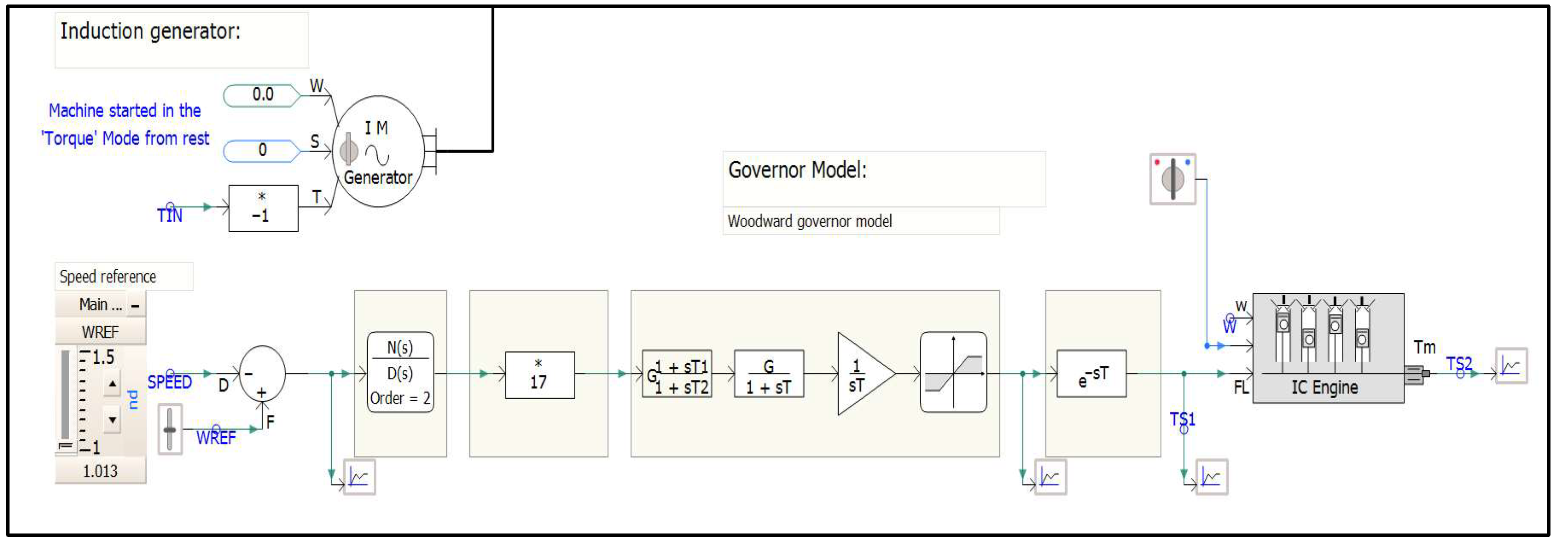
The governor—a critical control unit of the marine diesel generator—is designed based on the Woodward governor model, as illustrated in
Figure 1 [
22]. The model takes the error between the speed reference and the actual rotational speed as its input.
To precisely emulate the system’s dynamic characteristics, a second-order filter and a transfer function in the form of G/(1 + sT) are integrated into the control loop. Additionally, the physical delay inherent in the fuel injection system is incorporated as dead time using the exponential term e−sT. The resulting fuel command is then fed into the internal combustion (IC) engine model to generate mechanical torque, which is subsequently transmitted to the induction generator. The induction generator is modeled to start from a standstill in torque mode, reflecting realistic startup conditions.
Figure 2 presents the simulation results of the transient response characteristics from startup to steady-state, which were obtained to verify the reliability of the model. First, the rotational speed increases linearly after startup and accurately reaches the rated speed of 1.0 pu at approximately 4 s. During this process, the mechanical torque initially rises to provide acceleration and, upon synchronization, undergoes transient oscillations due to the governor’s control action before stabilizing in accordance with the load torque.
Regarding electrical characteristics, the terminal voltage starts from zero and rises sharply around the 4 s mark, demonstrating robust voltage regulation by maintaining a constant value near the rated voltage of 13.8 kV. Although high inrush current and reactive power peaks are observed during the initial startup phase, they converge within normal ranges alongside the real power as the system reaches the rated speed and voltage. Notably, the reactive power consumption decreases significantly after voltage stabilization, confirming that the reactive power balance of the system is well-maintained for stable power delivery.
2.2. Modeling of the Ship Propulsion Motor
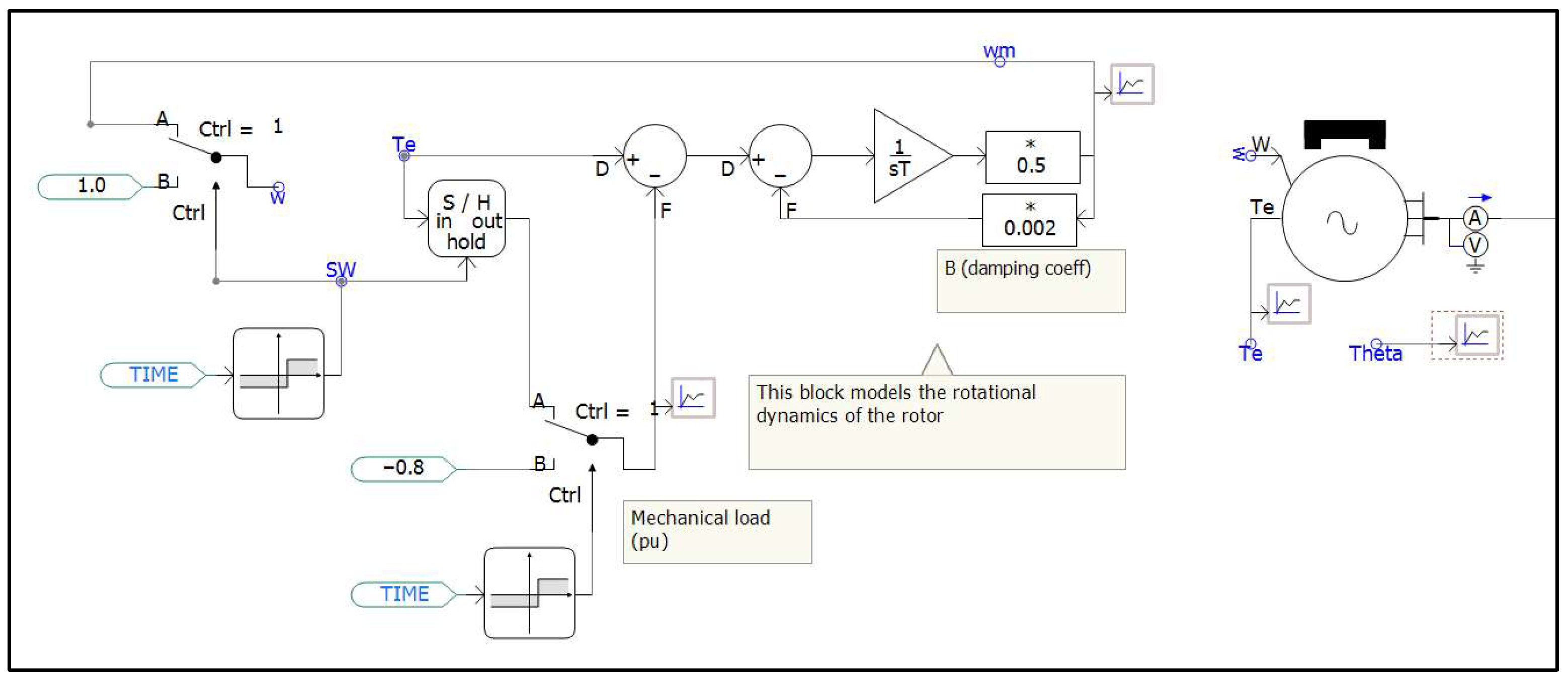
The ship propulsion motor model captures the conversion of electrical energy into mechanical torque, which is then transmitted to the propeller, as illustrated in
Figure 3. The rotational dynamics model developed in this study calculates changes in rotational speed based on the difference between the electromagnetic torque generated by the motor and the mechanical load torque applied to the propeller [
23].
In the core control loop of the model, the deviation between the electromagnetic and load torques is processed through an integration stage, which incorporates the system’s inertia to derive the rotational speed. To enhance model accuracy and incorporate frictional and viscous losses, a damping coefficient of 0.002 was employed. Furthermore, a scenario involving mechanical load fluctuations at specific time intervals was designed using switching blocks within the simulation. This setup enables analysis of the motor’s dynamic response to changing external environmental conditions, such as waves and currents. Finally, the calculated speed data are integrated into rotor position information, which serves as a feedback signal for precise vector control.
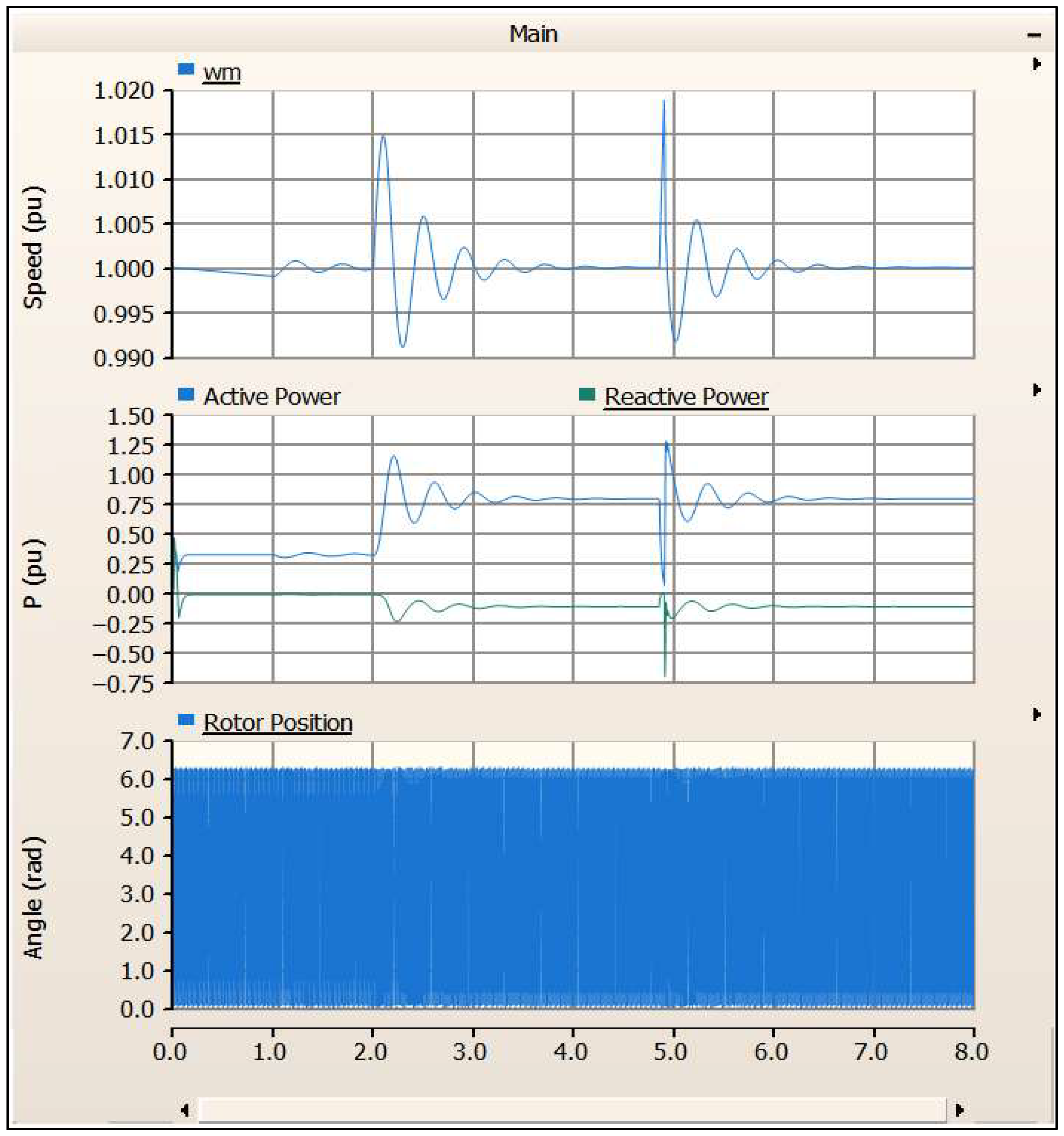
To verify the dynamic reliability of the developed model, step load changes were applied, and the responses of key system parameters were observed. As shown in the simulation results in
Figure 4, transient fluctuations in rotational speed were observed at approximately 2 and 5 s, corresponding to sudden changes in external load torque. However, due to the rapid responsiveness of the control system, the speed quickly converged back to the rated value of 1.0 pu within about 1 s, demonstrating excellent speed regulation performance.
During transients, active power responded promptly to meet load demands, thereby sustaining mechanical output, whereas reactive power settled after brief oscillations. Notably, the fact that the rotor position maintains a constant linear slope between 0 and 2 proves that the motor continues to operate stably without losing synchronization, even under abrupt load variations.
2.3. PV System Modeling
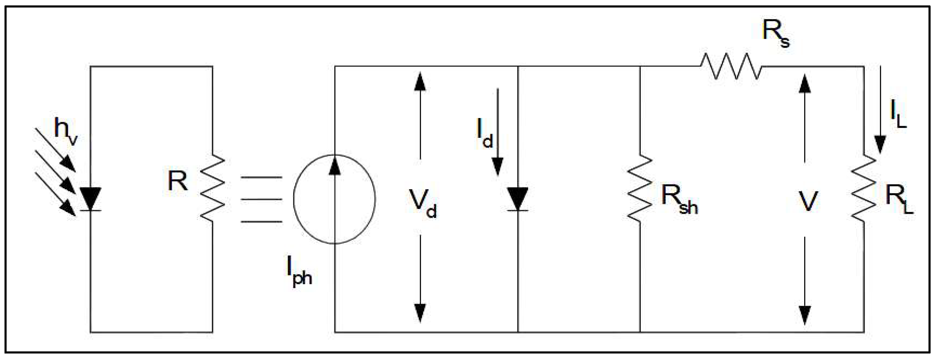
The equivalent circuit of a PV cell is theoretically composed of an ideal diode and a constant current source representing the photocurrent. However, as ideal diodes cannot be realized in practice, internal resistance components must be incorporated to account for physical losses. Specifically, a series resistor is included to represent contact and sheet resistance, while a shunt (parallel) resistor is used to model the leakage current within the device. Incorporating these parameters allows for a more accurate representation of the non-linear output characteristics of actual PV cells [
24].
The output current of the PV cell in the equivalent circuit is expressed as Equation (1):
In the case of an ideal PN junction diode under illumination, as shown in
Figure 5, the current
I flowing through the load can be expressed as Equation (2):
where IL is the output current, I
pk is the photocurrent, I
0 is the diode saturation current, n is the diode ideality factor, K is the Boltzmann constant, and q is the electron charge. The three variables—open-circuit voltage, short-circuit current, and fill factor—are key parameters related to energy conversion efficiency. Under the condition in which the output current I
L = 0, the open-circuit voltage V
OC can be expressed as shown in Equation (3):
The short-circuit current I
SC is obtained under the condition of zero terminal voltage (V
L = 0), where I
SC becomes equal to the photocurrent I
Pk. Through adjusting the magnitude of the load resistance connected to the cell, the maximum power output at the OOP can be determined, as expressed in Equation (4):
Finally, the power consumed by the load resistance, denoted as P
out, is given by Equation (5):
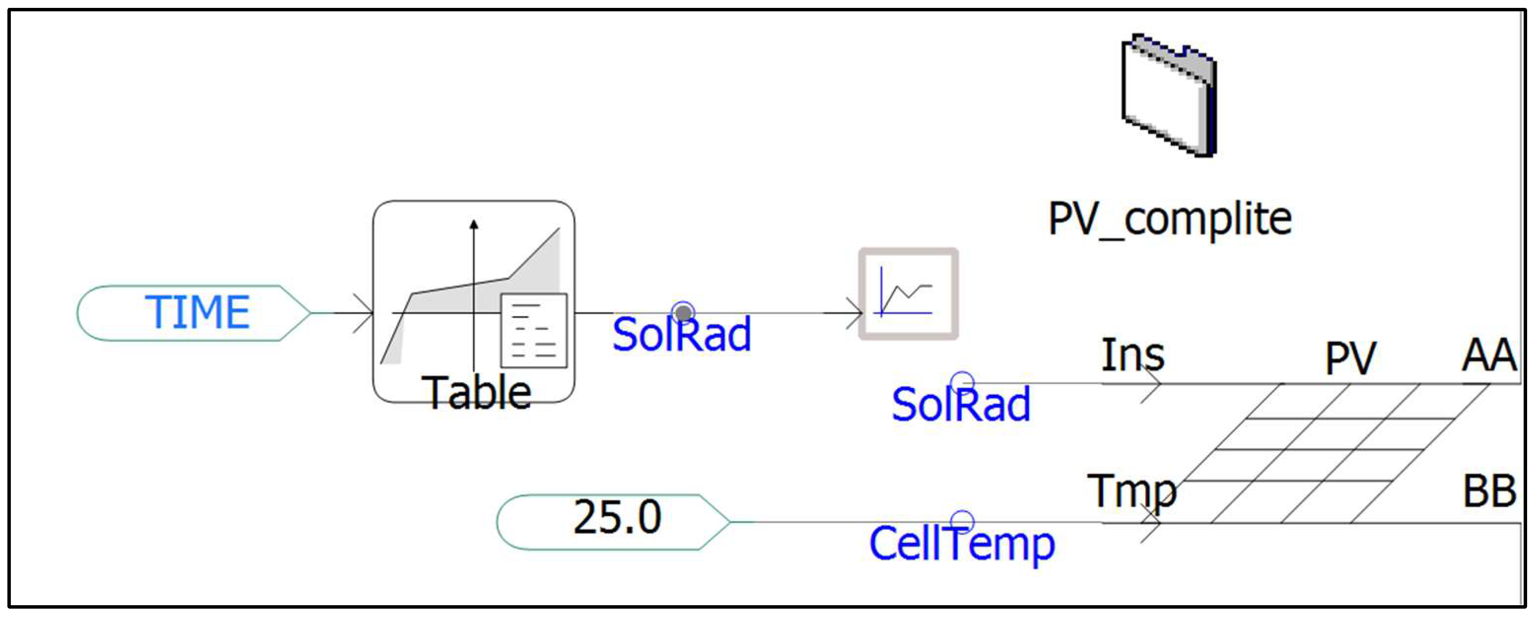
As shown in
Figure 6, PV models are implemented with Fortran code using the user-defined model (UDM) from PSCAD/EMTDC [
25].
2.4. Modeling of Energy Storage Systems
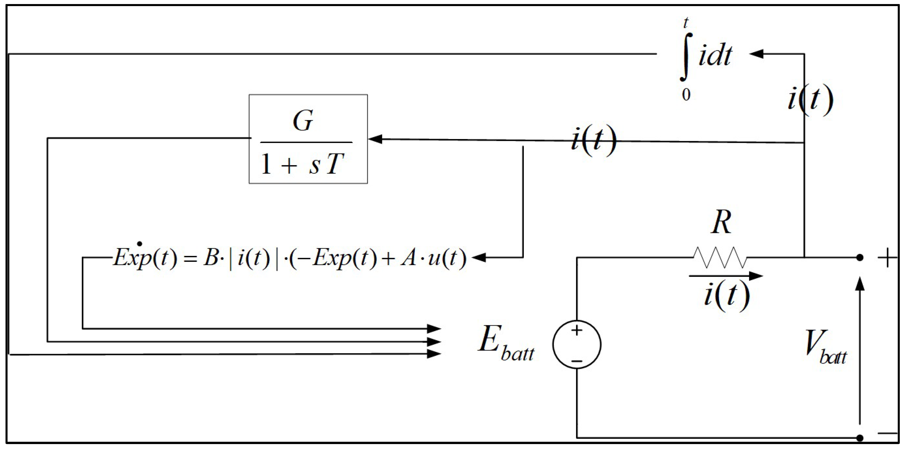
The output voltage of the battery is mathematically formulated by considering the voltage drop caused by internal electromotive force and the polarization effect. Although battery characteristics vary with temperature, this model assumes a constant temperature environment for simplicity. The term Exp(t) in Equation (6) represents the non-linear zone voltage characteristics and serves as an auxiliary function to derive the battery’s charge/discharge characteristic curve. The mode of operation is determined by u(t), where u(t) = 1 signifies charging and u(t) = 0 signifies discharging. The value of Exp(t) is calculated using the following differential equation [
26]:
The variables used in Equation (6) are defined as follows: the term Exp(t) represents a non-linear auxiliary function (in volts), while Is(t) denotes the battery current (in amperes). The operational state is determined by u(t), which indicates the charge or discharge mode of the system. Additionally, the constant A represents the voltage constant for the non-linear zone, while B is defined as the inverse of the non-linear zone time constant.
Equation (7) represents the mathematical model of the battery during discharge. Here, E
0 denotes the internal electromotive force, and R represents the internal resistance, which corresponds to the y-intercept of the battery discharge curve. The polarization constant K is a coefficient describing the polarization phenomenon within the battery. Furthermore, I
s represents the actual battery discharge capacity based on the discharge current, and, as such, it can be utilized to calculate the State of Charge (SOC). The term i* refers to the filtered current with a 30 s time constant. The definitions for the other variables are provided below:
The variables used in Equation (7) are defined as follows: Vbatt represents the battery terminal voltage, E0 denotes the internal electromotive force, the parameter K refers to the polarization constant or polarization resistance, Q indicates the total battery capacity, Is is the actual battery charge/discharge capacity, and R represents the internal resistance. Finally, i denotes the battery’s output current, and i* represents the filtered current processed through a low-pass filter.
Theoretically, if I
s = 0, the polarization resistance becomes infinite, which does not occur in practice. Based on charging characteristics, it is observed that approximately 10% of the battery capacity is moved by the influence of polarization resistance. This phenomenon is expressed as
Equation (9) represents the charging characteristics of the battery. Note that the voltage drop due to polarization is expressed differently compared with the discharge equation:
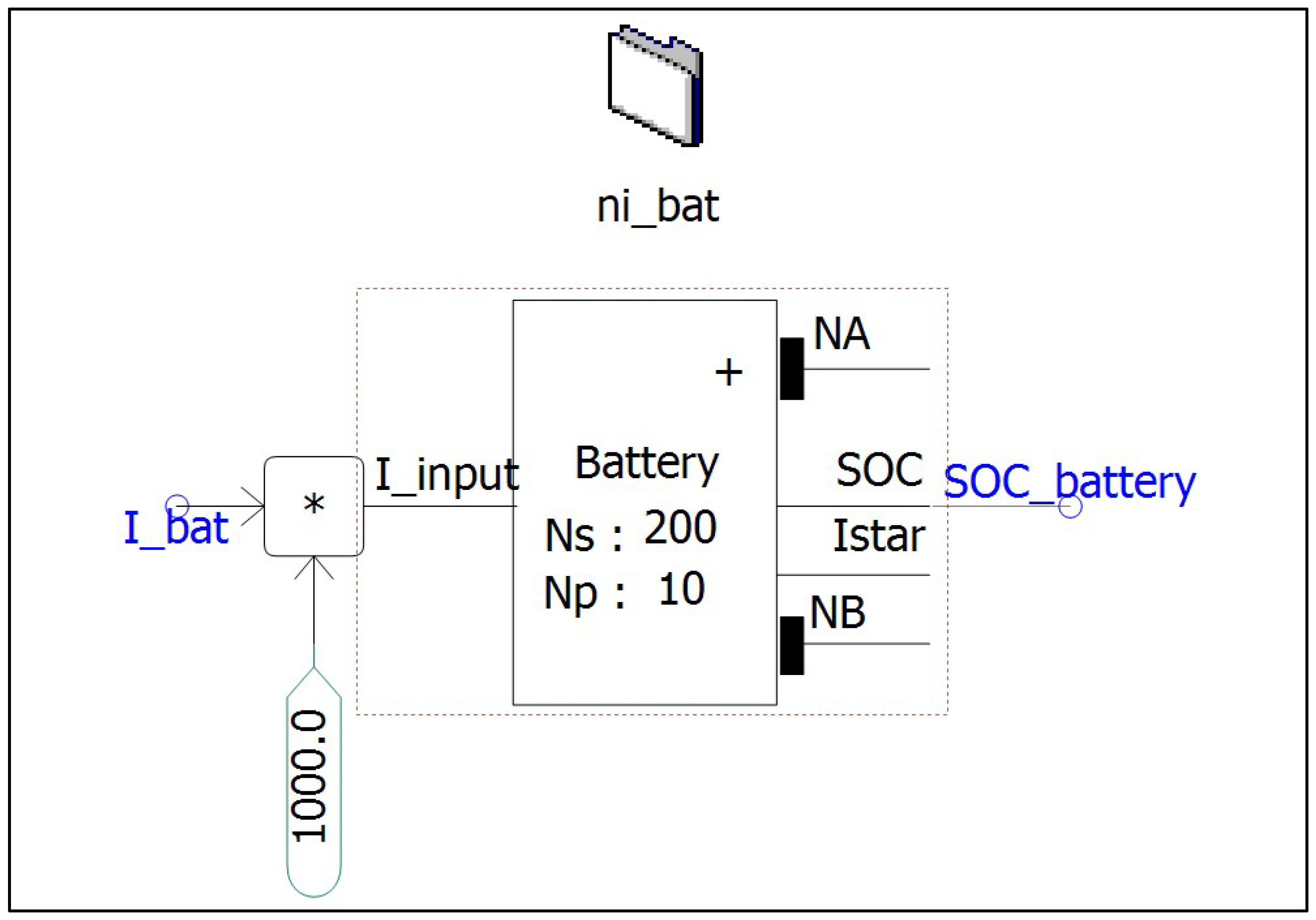
Figure 7 illustrates the schematic model of a battery, where the battery terminal voltage can be determined using the charge/discharge current at the battery terminals.
The battery model is extended to include thermal dynamics and degradation:
where C is the thermal coefficient (rise limited to 5 °C under 40 °C maritime ambient), T is the temperature, and D is the degradation factor (fade 0.5% per 100 cycles, critical for long voyages). This prevents overestimation, with a rate of <0.2% per operation in simulations. Our model aligns with recent maritime ESS advancements, including deep learning-based health prediction for degradation [
27]. As shown in
Figure 8, battery models are implemented with Fortran code using the UDM from PSCAD/EMTDC [
25].
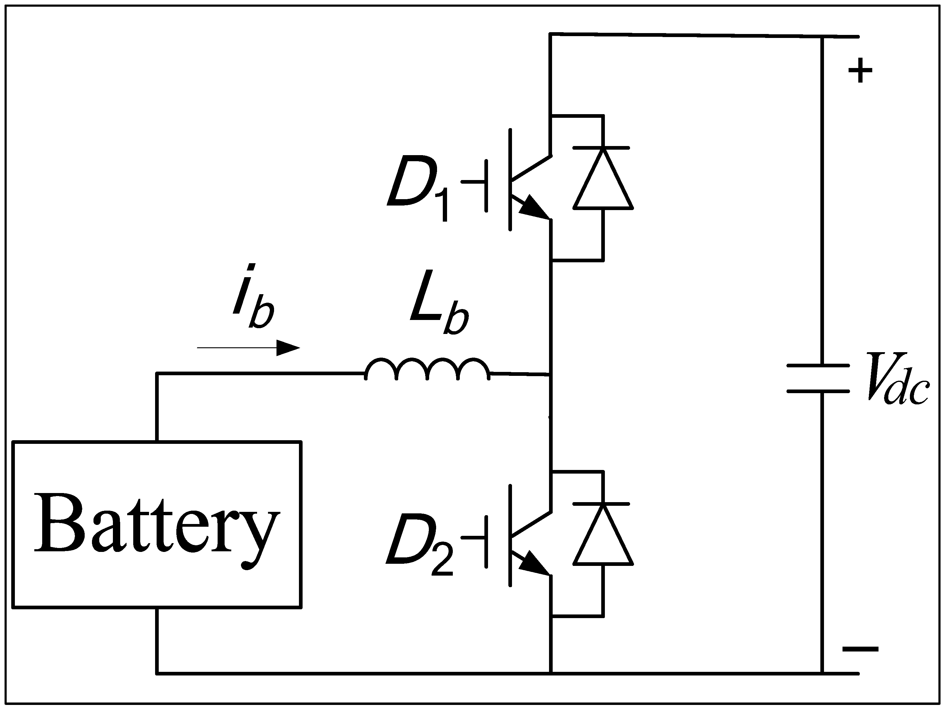
A battery energy storage system is composed of a battery, a bidirectional converter, and a controller. This system operates bidirectionally: the battery can be charged with surplus energy, and the stored energy can then be supplied back to the load. As shown in
Figure 9, the battery is connected to the DC link via a bidirectional DC/DC converter. As photovoltaic (PV) output is intermittent, it often fails to meet the load demand independently; therefore, the system is designed to compensate for the fluctuations in PV power output.
The primary objective of the converter is to control the battery output (P
BAT), which is determined by the grid power (P
grid) and PV output (P
PV):
The bidirectional DC/DC control (Equation (10)) is extended to an advanced EMS with model predictive control (MPC) for multi-objective optimization. The objective function minimizes:
where w
1–w
3 are weights (e.g., w
1 = 0.6 for power balance, w
2 = 0.3 for SOC, w
3 = 0.1 for efficiency), SOC
dev is the deviation from 50% reference, and Eff
loss is the estimated loss (<5%) (constraints: SOC 20–80%, power limits). This predicts 5 s horizon fluctuations, achieving 15% better efficiency (settling time 0.6 s in variable-speed cases) than basic balancing.
The charge/discharge control of the converter operates in two modes, as follows:
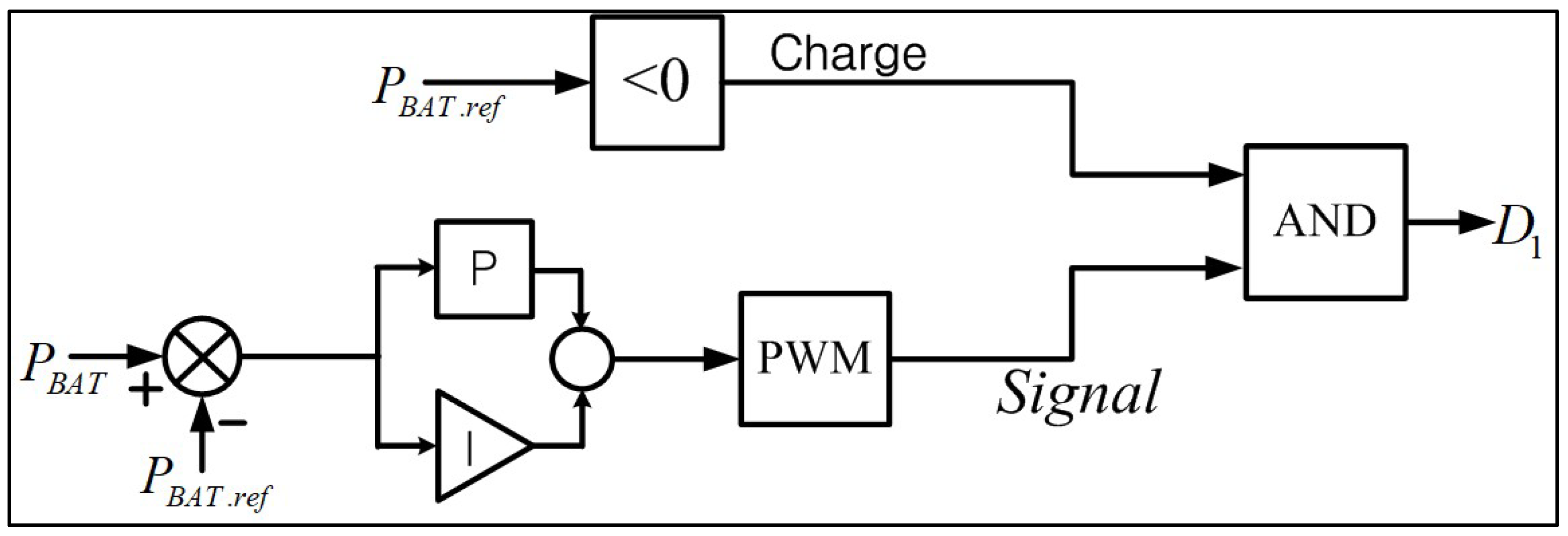
Charge mode—If P
BAT is negative, switch D1 is activated, and the converter operates as a boost converter.
Figure 10 illustrates the control method for the charging mode.
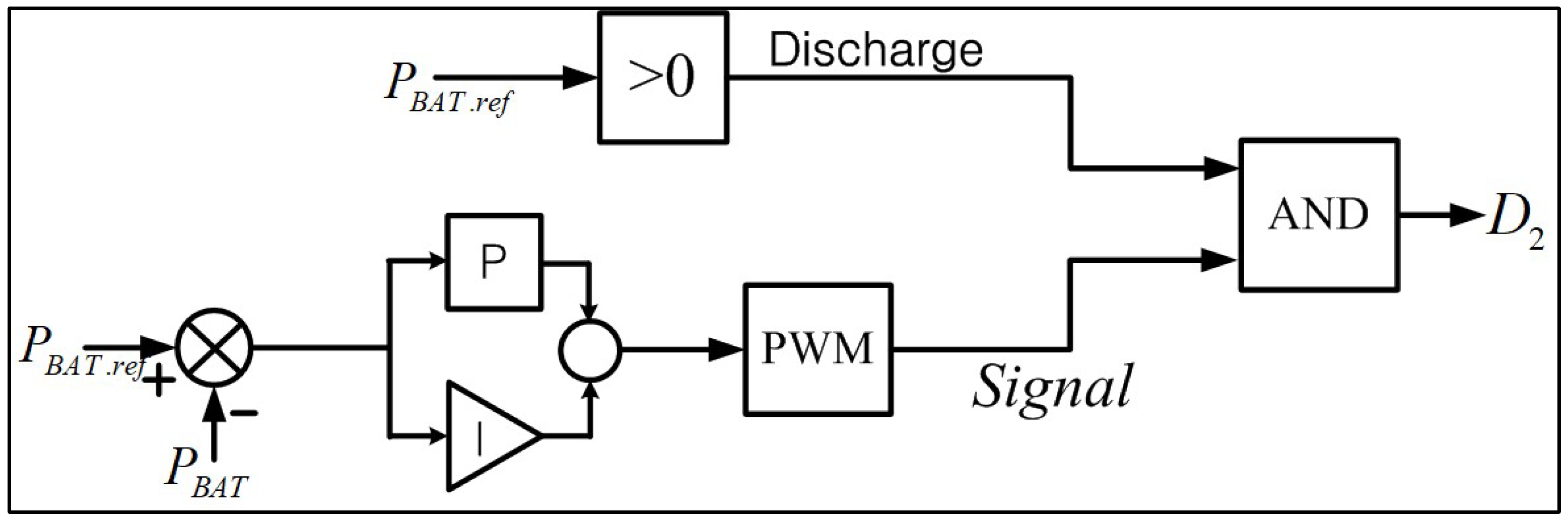
Discharge Mode—If P
BAT is positive, switch D2 is activated, and the converter operates as a buck converter.
Figure 11 illustrates the control method for the discharging mode.
2.5. Comparison of the Proposed Model with State-of-the-Art Ship Microgrid Studies
While previous works [
5,
8,
15,
20] have explored BESS integration or using HESSs in ship microgrids, few have addressed EMT-level modeling of propulsion motor-level transients under irregular wave conditions.
As summarized in
Table 1, the proposed framework is the first to achieve the full EMT-level integration of propulsion motor localized control with a PV-BESS hybrid system, explicitly addressing ship-specific transient characteristics and validated against sea-trial-derived parameters.
3. Simulation of Integrated Electric Ship Power Systems
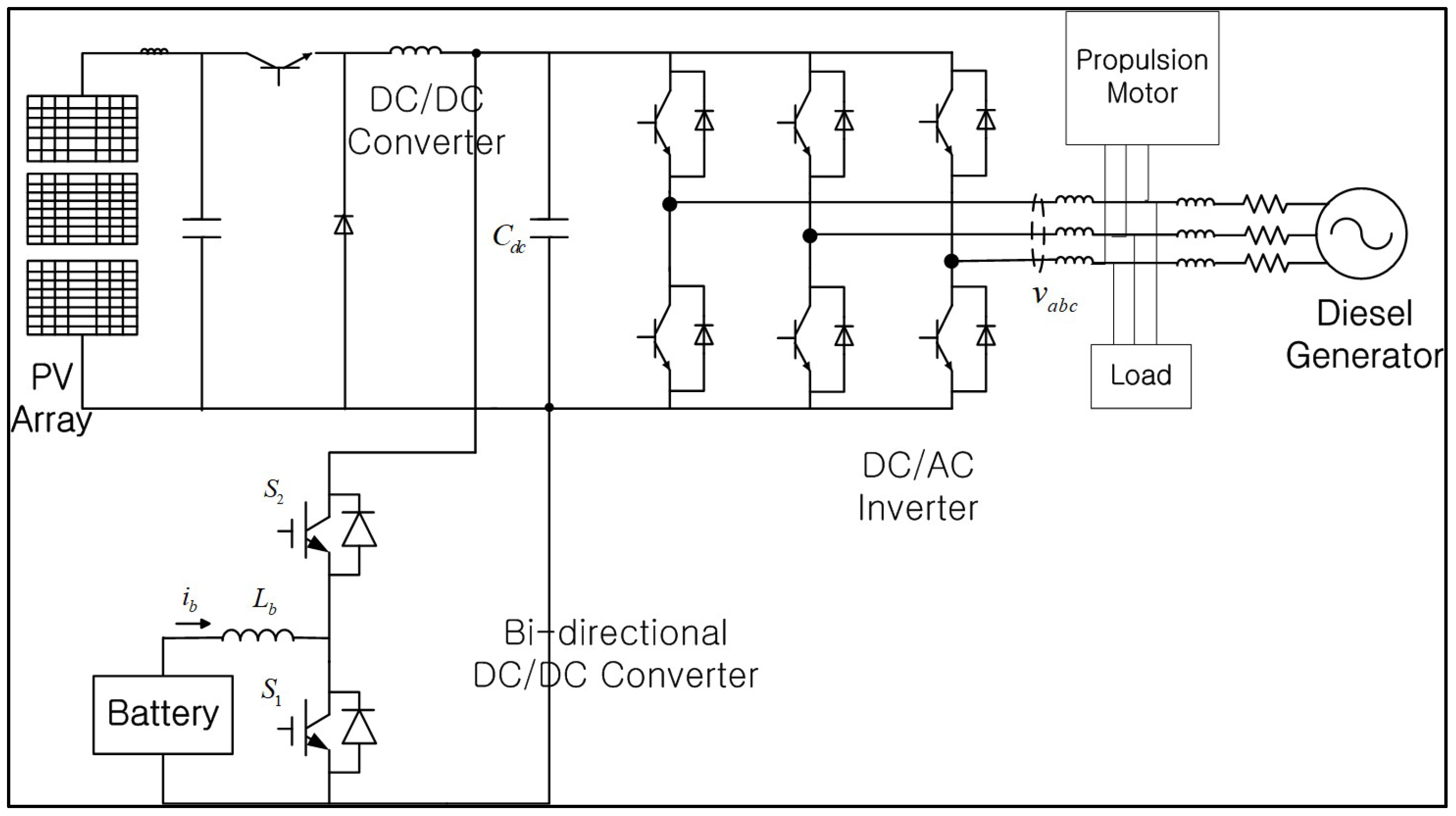
In this study, an integrated simulation model was proposed by combining the core components of the power generation system, propulsion system, and BESS to precisely analyze the dynamic characteristics of electric propulsion ships; the overall system configuration is illustrated in
Figure 12. The power generation system includes a diesel generator based on a Woodward governor that accounts for fuel injection delays, as well as a PV array formulated with variables such as the output current, photocurrent, and diode saturation current. In particular, the PV model defines the energy conversion efficiency through open-circuit voltage, short-circuit current, and fill factor, and is designed to derive maximum power at the OOP by adjusting the load resistance. The energy storage system consists of a battery, a bidirectional DC/DC converter, and a controller, which compensate for the intermittency of the PV output and meet load demands. The battery terminal voltage is calculated by electrically formulating the voltage drop caused by the internal electromotive force, internal resistance, and the internal polarization effect, while a differential equation introducing an auxiliary function, Exp(t), is applied to reflect the characteristics of the non-linear zone.
The bidirectional converter maintains a stable DC-link voltage by switching between charging mode (boost) and discharging mode (buck), based on the difference between the grid power demand and the PV output. Finally, the ship model is designed to calculate the vessel’s speed based on the thrust generated by the propeller. While ship equations of motion that consider factors such as hydrodynamic resistance are essential for accurate speed calculation, the detailed variables required for these equations can typically only be obtained through experimental measurements conducted on actual vessels. However, as directly securing such data is practically impossible, this study ensured the practical reliability of the model by indirectly utilizing and applying data obtained from existing experimental results in the simulations.
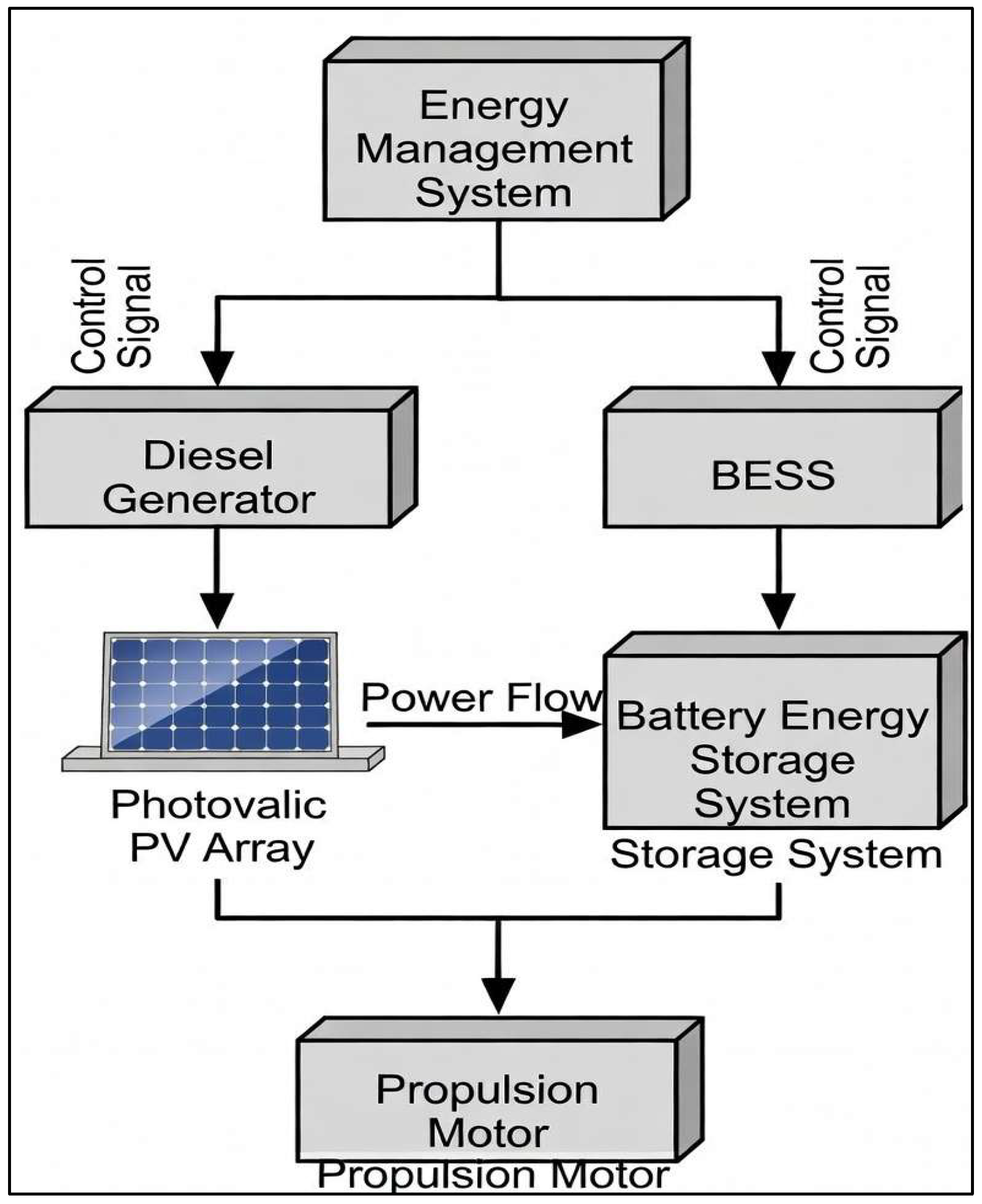
To improve the clarity of the system configuration and control hierarchy, the overall power flow and control signal paths are illustrated in
Figure 13.
The microgrid electric propulsion system proposed in this study is composed of a PV array, a battery, and a diesel generator, with each component organically integrated through power conversion devices. Regarding the system architecture, the PV array and the battery are each connected to a common DC link via independent DC/DC converters, after which power is supplied to the ship’s internal grid and the propulsion motor through a DC/AC inverter. In this configuration, the battery plays a pivotal role in controlling the overall power quality of the system by providing real-time compensation for PV energy, which varies significantly depending on weather conditions, thereby maintaining a constant flow of energy into the grid.
To maximize energy efficiency, the PV system utilizes a DC/DC converter applied with MPPT control, designed to maintain peak power output regardless of changes in solar radiation or temperature. Simultaneously, the battery undergoes charge and discharge control through a bidirectional DC/DC converter. The primary objective of the converter is to regulate the battery output, which is determined by the difference between the required grid power and the PV output.
The battery’s charge and discharge control operates primarily in two modes: when the reference value is negative, switch D1 is activated to charge the battery using a boost converter method; conversely, when the reference value is positive, switch D2 is activated to discharge energy using a buck converter method. This control strategy contributes to the immediate stabilization of the system output in response to sudden load fluctuations within the electric propulsion system.
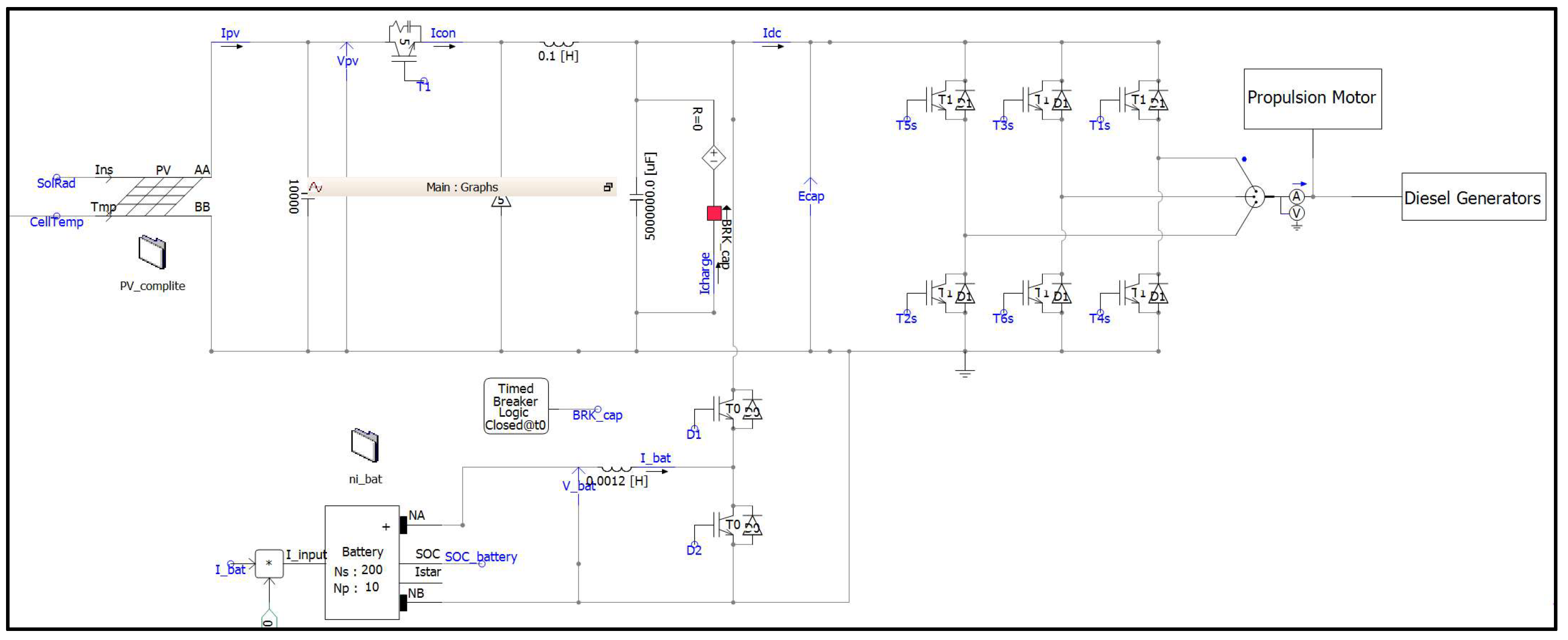
Figure 14 illustrates the implementation of this complex power flow and the dynamic characteristics of the battery using the PSCAD (v50) software, through which the system’s stability was verified under changes in the ship’s propulsion load. The main simulation parameters are summarized in
Table 2 to ensure reproducibility and clarity.
3.1. Case 1: Constant Speed
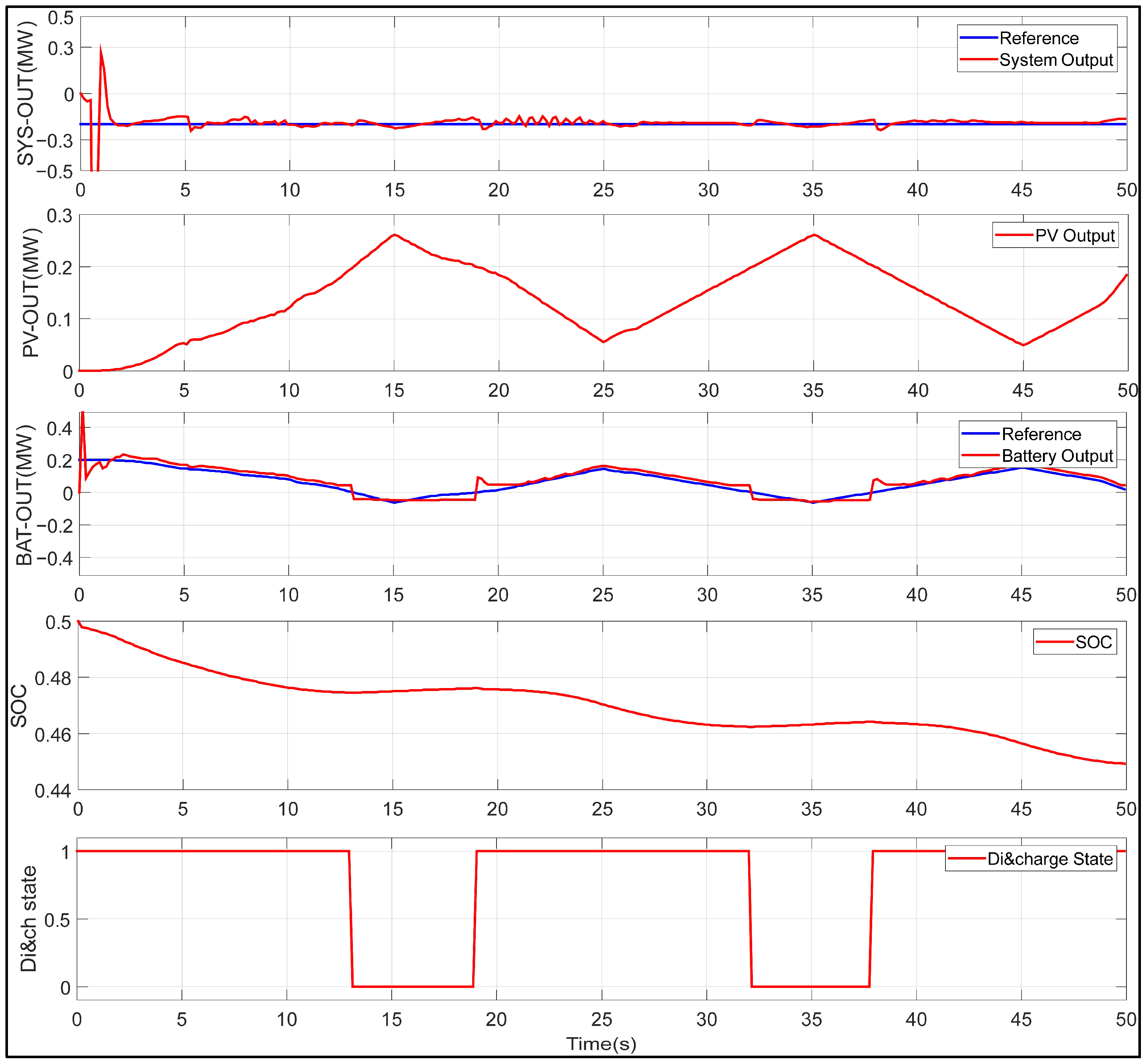
Figure 15 presents the PSCAD simulation results, illustrating how the overall system output remains constant through the proposed control strategy when the microgrid-based electric propulsion system is in a steady-state cruise mode. A detailed analysis of the dynamic behavior observed in the simulation is given below.
The total system output remains stable with no fluctuations, reflecting the constant propulsion load during steady-state cruising. Despite periodic variations in PV output caused by changing weather conditions, the BESS provides immediate compensation, effectively mitigating intermittency. The battery charges during PV surpluses and discharges during shortfalls, effectively compensating for power deficits. The charge/discharge state graph confirms this balancing through adaptive switching between charging (1) and discharging (0) modes, synchronized with PV fluctuations. The battery’s SOC changes with a gentle slope following this continuous compensation process, which supports the fact that the battery is effectively regulating the difference between the grid power demand and the PV output. In conclusion, this simulation demonstrates that the control strategy of the bidirectional DC/DC converter is highly effective in stabilizing the output of the electric propulsion system, even under the energy fluctuations occurring during vessel operations.
3.2. Case 2: Variable Speed
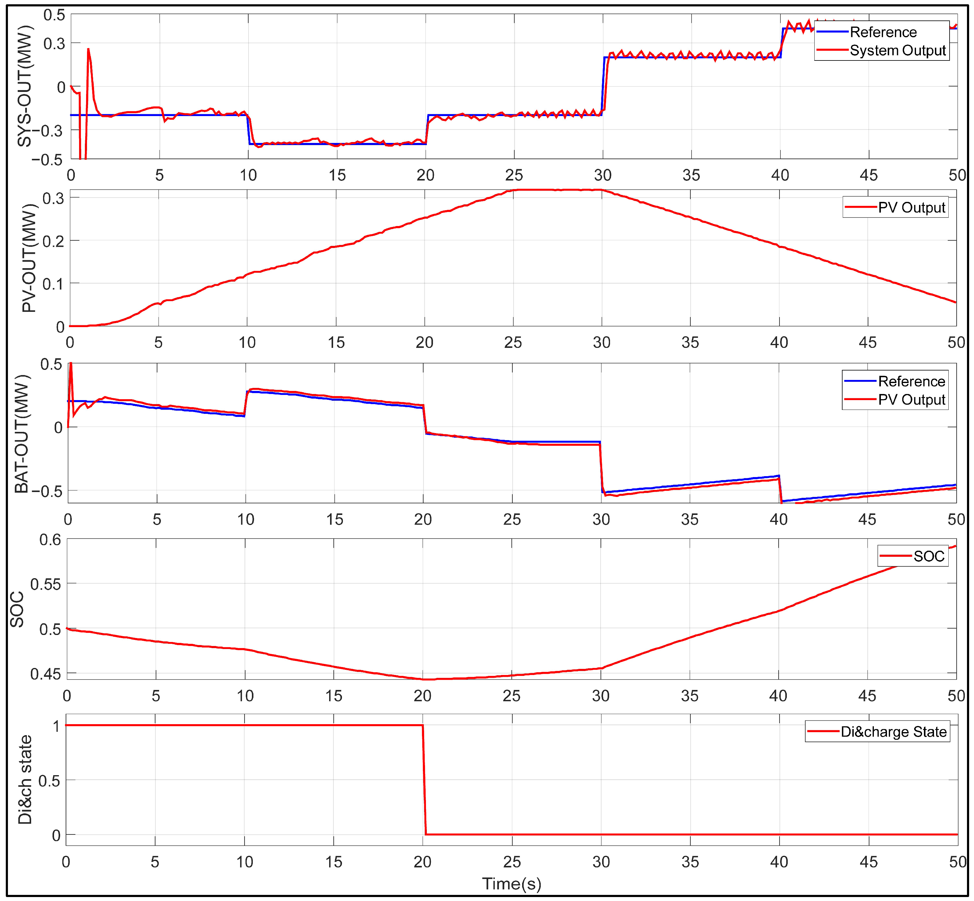
Figure 16 shows the system’s dynamic response to vessel speed variations in a PSCAD-simulated microgrid electric propulsion system. The total output follows stepwise propulsion load changes during acceleration/deceleration, with DC-link voltage deviation limited to <±1.5%. The BESS compensates for PV intermittency by calculating battery output as the real-time difference between demand and generation, charging during surpluses and discharging during deficits. Charge/discharge switching synchronizes with load and PV fluctuations, maintaining the SOC within 20–85% and preventing instability. Overall, the control strategy ensures robust power quality (settling time < 0.8 s) and efficiency (peak-shaving 25–30%) under variable-speed conditions, mimicking real maritime environments.
3.3. Model Evaluation and Comparison
The proposed EMT model was evaluated using quantitative performance metrics under constant- and variable-speed conditions.
Key metrics include the following:
DC-link voltage deviation: <±1.8% (within ±2% requirement for ship power systems).
Settling time after load step: <0.8 s.
Peak-shaving ratio: 25–30% under variable-speed operation.
Battery SOC variation: 18–88% (safe range).
Model accuracy was validated against simplified parameters derived from sea-trial propulsion dynamics [
12,
13]. The simulation error in thrust profiles was <3%, confirming reasonable fidelity for initial design assessments.
To validate the model fidelity, the simulated thrust profiles and DC-link voltage responses were compared against simplified parameters and operational trends derived from sea-trial data reported in [
12,
13]. The root mean square error (RMSE) for thrust fluctuations under variable load steps was calculated to be less than 3%, and the DC-link voltage deviation remained within the target range of ±1.8% (see
Figure 15 and
Figure 16). Although full-scale experimental validation on an actual vessel was not conducted in this study due to practical constraints, this indirect validation using literature-derived propulsion dynamics confirms that the proposed EMT model provides reasonable accuracy for preliminary design and stability assessment purposes.
As shown in
Table 3, the proposed hierarchical control strategy outperforms the conventional droop control and no-BESS cases in all key performance metrics. These comparisons were derived by referencing the dynamic responses observed in the existing PSCAD simulations (
Figure 15 and
Figure 16) against performance benchmarks reported in the literature.
4. Conclusions
In this study, we present a PSCAD/EMTDC-based dynamic modeling framework for evaluating the performance of shipboard microgrids in electric propulsion vessels using EMT simulations. The hybrid configuration, including a PV array, BESS, and diesel generator, addresses power quality and operational stability in variable maritime environments.
The key contributions are as follows: (1) integration of MPPT for the PV array and bidirectional DC/DC converter control for the BESS, effectively compensating for solar intermittency; (2) simulations under constant- and variable-speed conditions confirming the dynamic response to propulsion load changes while maintaining a stable DC-link voltage; and (3) incorporation of parameters from existing experimental propulsion dynamics data—where direct onboard measurements are often impractical—achieving reasonable fidelity for initial design assessments. These elements distinguish the proposed framework from previous works that lack ship-specific transient handling.
The simulation results demonstrate robust power balancing and load-following in a representative hybrid ship microgrid. These findings highlight the value of renewable-integrated energy storage for efficient diesel generator operation and support the IMO’s net-zero GHG emissions goal by or around 2050.
This work provides a practical simulation foundation for developing EMSs for next-generation smart, eco-friendly ships and designing renewable-based marine power networks.
Although a full lifecycle cost analysis is beyond the scope of this EMT-focused modeling study, preliminary estimates based on the achieved peak-shaving ratio (25–30%) indicate significant benefits. As summarized in
Table 4, the proposed system could achieve 12–18% fuel savings and corresponding CO
2 emission reductions.
While the present model demonstrates good transient performance, it relies on parameters extracted from existing sea-trial literature rather than direct onboard measurements from the target vessel. Future studies should incorporate real-time data from hybrid propulsion test vessels to achieve higher validation confidence.
Future research could extend this framework by incorporating realistic stochastic load profiles to simulate irregular wave-induced thrust fluctuations (e.g., random wave height and period variations using the JONSWAP spectrum), propeller cavitation effects, and environmental disturbances from ocean currents. This would provide even higher fidelity to real maritime operating conditions while maintaining the current EMT-level computational efficiency.
Additionally, quantitative performance indicators—such as fuel savings estimates, peak-shaving effectiveness, or BESS cycle life impact—could be assessed via parametric studies or co-simulation with voyage planning tools.
Furthermore, incorporating advanced energy management techniques (e.g., model predictive control or reinforcement learning-based optimization) and evaluating hybrid storage configurations (e.g., battery with ultracapacitors) would enhance the framework’s applicability to next-generation all-electric or hybrid propulsion vessels.