Article

A Reconfigurable Monopole Antenna Based on a Triangular Cylindrical Origami Structure

1
Department of Civil, Environmental and Mechanical Engineering—DICAM, University of Trento, 38123 Trento, Italy
2
Department of Electronics and Communication Engineering, Centre for Flexible Electronics and Advanced Materials, Amrita Vishwa Vidyapeetham, Kollam 690525, India
3
Fondazione Bruno Kessler (FBK), 38123 Trento, Italy
*
Author to whom correspondence should be addressed.
Electronics 2026, 15(13), 2914; https://doi.org/10.3390/electronics15132914
Submission received: 26 May 2026 / Revised: 29 June 2026 / Accepted: 1 July 2026 / Published: 3 July 2026

Abstract

This work presents the design of a deployable reconfigurable monopole antenna based on a triangular cylindrical origami structure (TCO). TCO structures are three-dimensional geometries able to modify their structure if subjected to specific solicitations. They are particularly useful for the design of deployable antennas in satellite communication applications. A TCO structure begins from a two-dimensional base composed of an N-faced polygon around which are triangles arranged in a circular pattern to give the structure a cylindrical shape once assembled. The structure is closed with an upper face that can move when stressed. In fact, by applying a force on the upper face, the structure can bend through a combined movement of rotation and translation, expanding or contracting its physical length and consequently the operative frequency. The use of a TCO structure provides a light, cheap, compact, and reconfigurable monopole antenna, particularly suitable for satellite applications. Moreover, by using multiple TCO segments that can be singularly activated, it is possible to control the antenna’s electrical length and consequently obtain a frequency reconfigurable antenna. To demonstrate the effectiveness of such a structure, an antenna prototype based on a TCO is been designed, fabricated, and numerically and experimentally assessed. The obtained results demonstrate the potentialities of such antenna, especially for satellite communication applications.

1. Introduction

It is well known that antennas play a key role in every communication system, and the significant advancements in terrestrial and satellite communication systems have required the development of light, compact, high-gain radiating systems [1,2,3]. In particular, satellite communications applications require very-high-gain antennas with a focused main beam and a very compact size [1]. Reflector and lens antennas are widely used in communication systems as these antennas are characterized by a focused beam pattern and very high gain. Although reflector and lens antennas, due to their high performance, are perfect candidates for terrestrial communication systems [2,4], they are often mechanically fragile, bulky, and typically too large to be compatible with small satellites and launcher vectors. Recent practical engineering applications make use of the ancient technique of paper folding called origami to obtain a compact and deployable structure. The origami concept can be used in various practical applications, e.g., refs. [5,6], ranging from architecture to robotics and medical devices [7]. In recent years, there has been a growing trend of utilizing the origami concept for the design of deployable and reconfigurable antennas [8,9,10]. The idea of origami was first used in satellite reflector antennas, which require miniaturized structures because of the small spaces of launcher vectors. The origami concept has also been used, integrated with electromagnetic theory, for the realization of reconfigurable antennas [11,12,13,14,15]. In particular, origami antennas gained popularity thanks to their ability to mechanically reconfigure themselves by changing their physical geometry and consequently changing their radiative properties. With the origami technique, it is possible to transform 2D structures into a range of 2D and 3D shapes by using different rigid foldability mechanisms. Origami applied to an antenna permits changing the antenna’s shape or element separation, obtaining control of various radiation performance parameters such as beam forming and scanning range. Origami antennas are multifunctional, and they have the potential to develop new reconfigurable electromagnetic systems with various transformational abilities [16,17,18,19,20,21]. A typical origami antenna is made by using paper or a flexible polymer as an antenna substrate and a conductive ink as metal parts, but the flexible substrate is not resistant to heavy mechanical stresses, and the metallic ink, such as copper-based ink, does not offer enough conductivity to guarantee good radiation performance [22]. Other techniques have been developed over the years to obtain three-dimensional structures and improve the robustness of these structures [23,24]. Some techniques employ different actuators for various folding and unfolding operations to achieve reconfigurable characteristics; they use servo motors, springs, or memory-form alloys [10]. Origami antennas offer the advantage of reconfigurable frequency by changing the antenna’s physical geometry. A particularly interesting three-dimensional origami structure is the triangular cylindrical origami structure, which could be composed of different elementary cells, each of which can be in two bistable states by applying a vertical or rotational force. The TCO cell is properly designed and is subjected to a phenomenon called bistability; in the absence of a mechanical solicitation, the cell remains stable. If a suitable force is applied to the structure, it can assume two states: compressed or deployed. Once a given state is reached, it is kept in the absence of further solicitations. In this paper, a deployable frequency reconfigurable multi-TCO monopole antenna is presented. The monopole’s effective electric length can be reconfigured by activating each TCO segment by means of a miniaturized actuator aimed at changing the state of the single TCO cell. In this way, it is possible to change the antenna’s electrical length and consequently its operating frequency. An antenna prototype made with four different TCO segments is designed, fabricated, and numerically and experimentally assessed, showing a frequency reconfigurability reached by using a three-dimensional multi-TCO structure. Concerning the innovations introduced in this work. It is well known that there are different applications of TCO structures for antenna design, such as Miura-ori, Yoshimura, or other origami mechanisms applied to a reconfigurable antenna. However, this structure requires accurate, precise and accurate actuators to guarantee mechanical stability, repeatability, and frequency selection stability. Thanks to the bistable behavior of the considered TCO cells, which always permit only two stable states, and consequently two fixed lengths, it is possible to obtain an accurate and repeatable frequency selection, To the best of the authors’ knowledge, nobody has used a multi-TCO structure with bistable behavior to obtain a reconfigurable radiating structure. The proposed prototype is intended as an auxiliary radiation system in case of failure of the principal antenna. The work is structured as follows: Section 2 reports the multi-TCO concepts, the related mathematical formulation, and the antenna structure. The monopole prototype is described in Section 3. Numerical and experimental assessments are reported in Section 4. The conclusions and suggestions for future developments are finally reported in Section 5.

2. The TCO Structure

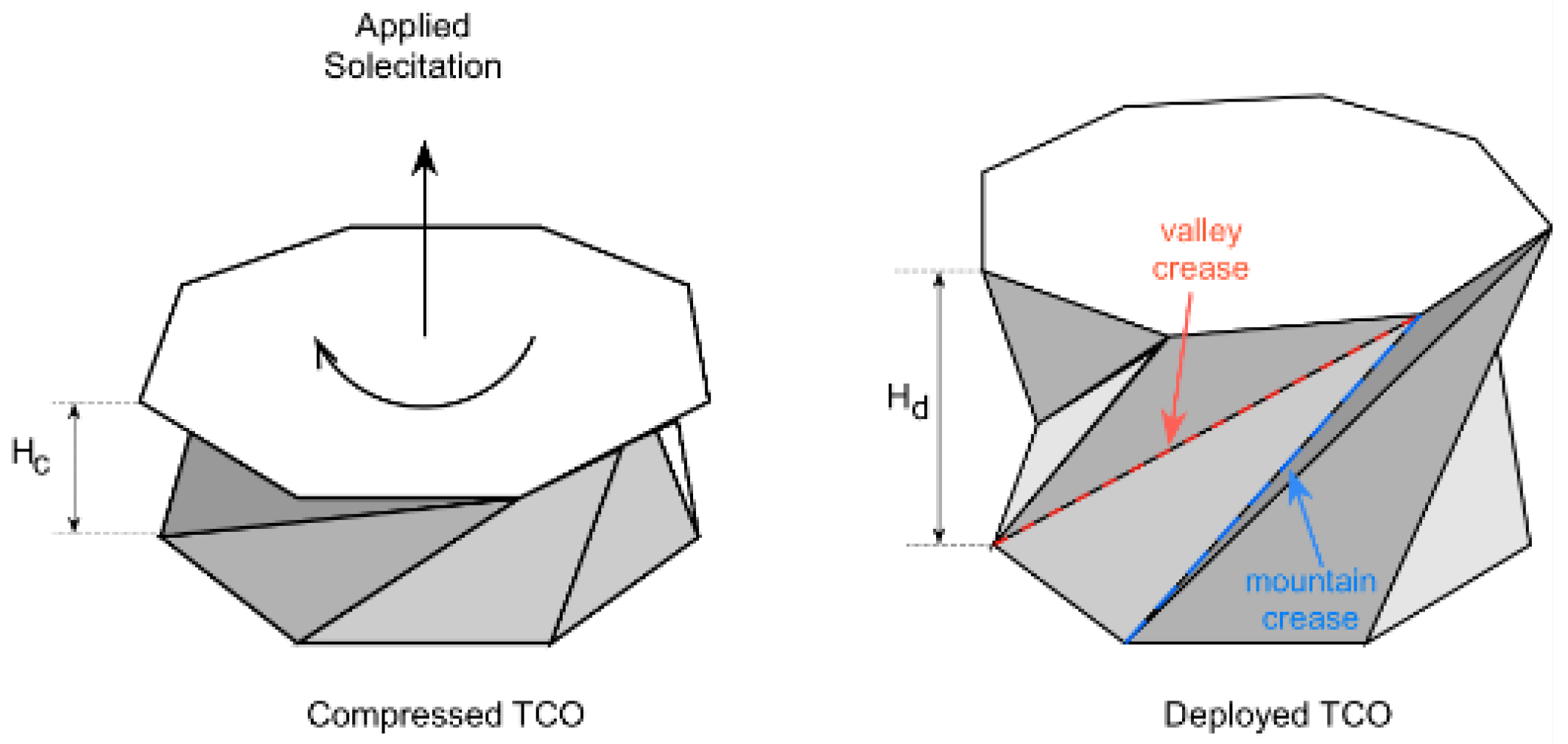
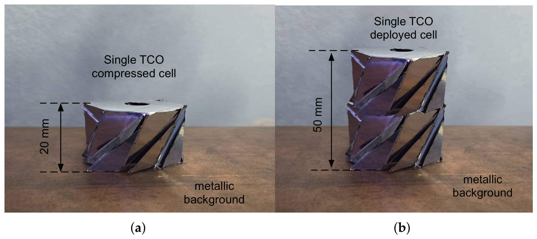
Let us start with a detailed description of the TCO cell. It is made by a couple of two-dimensional bases composed of a polygon with N faces, around which a set of triangles is arranged following a circular pattern to obtain a cylindrical structure once assembled. As shown in Figure 1, the bottom face is kept fixed while the upper face is free to move if stressed. In fact, by applying a force on this face, the structure can bend through a combined movement of rotation and translation [25]. In particular, by pushing the upper face downwards or by rotating it, the surrounding triangular faces incline and bend; these inclinations cause the vertices of the upper surface to move in a clockwise direction, effectively causing the face itself to rotate, in addition to the vertical translation downwards due to the force exerted. If the solicitation is too small, the structure will return to its starting configuration (the one at maximum height) like a spring under elastic compression; however, if the structure is subjected to a strong mechanical displacement, it will remain compressed in this new configuration, even once the force has stopped, and the TCO structure remains stable because it is in a situation of minimum potential energy: this phenomenon is called bistability [25,26]; that is, there are not one but two situations compressed and deployed where the structure, also in absence of forces, keeps its stability.
Concerning the TCO cell geometry, we used the same parameters reported in [25], where a detailed analysis of the TCO bistability behavior and all the information related to mechanical fatigue, repeatability, compression, and deployment forces are reported.

Antenna Structure

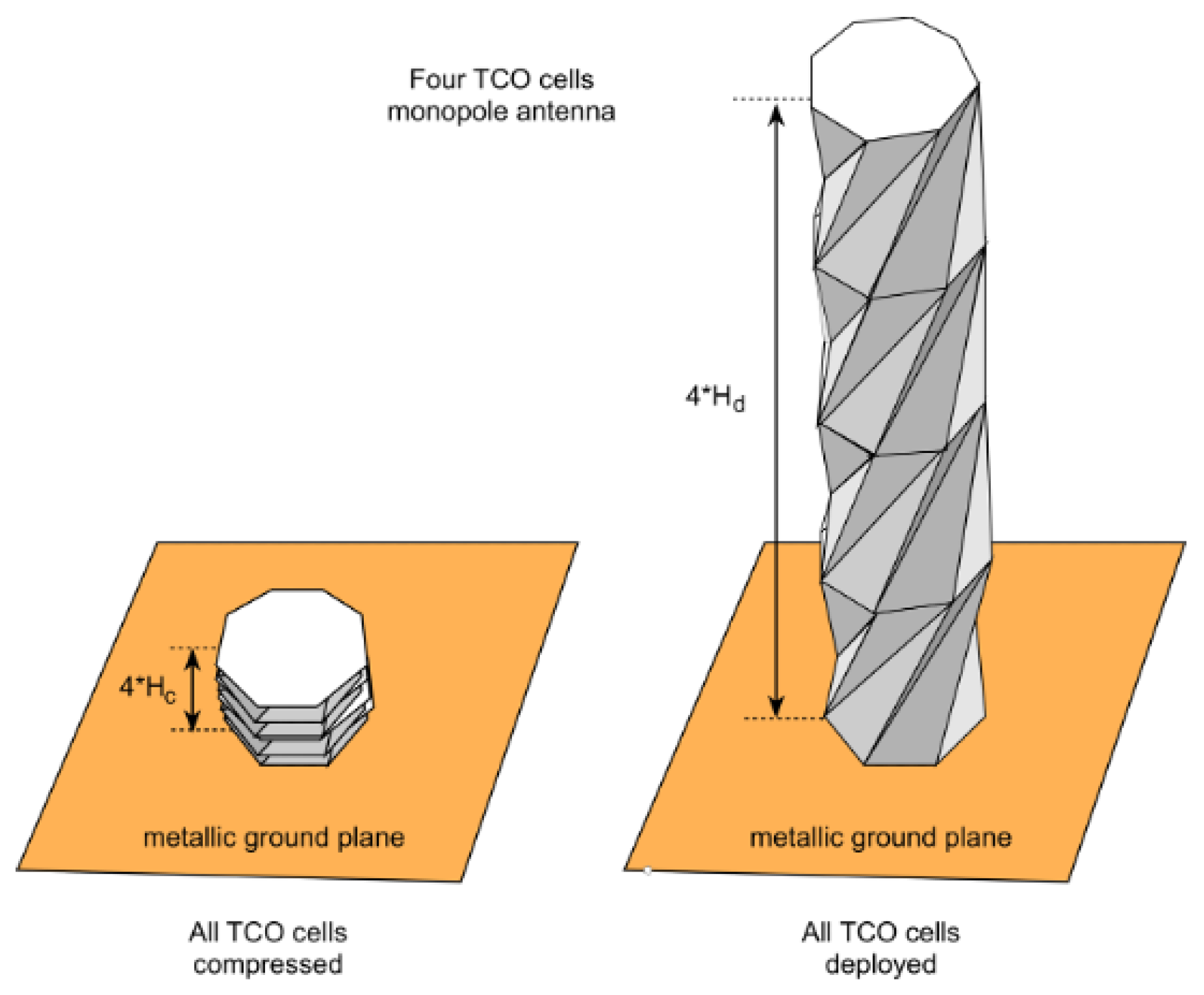
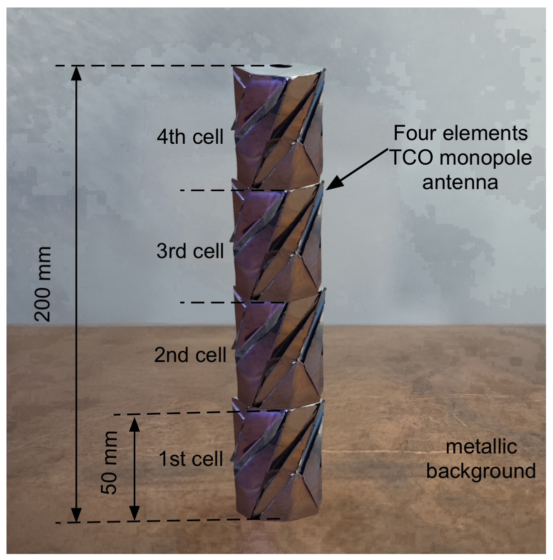
The antenna structure reported in Figure 2 is composed of four TCO cells, each characterized by H c = 0.02 m and H d = 0.05 m, and a metallic ground plane. The feeding is provided with a coaxial connector. Considering that each cell can be set to the compressed or deployed state, the antenna length can assume five different states corresponding to five different resonance frequencies, as reported in Table 1.
It is worth noting that the limited discrete operating states only depend on the number of considered TCO cells. It is certainly possible to increase the state’s number by adding further TCO cells. The radiative properties of such an antenna can be derived by considering the formulation reported in [27], as the hypothesis of a small-thickness conductor is not valid due to the horizontal dimension of the TCO cell. In particular, the following formula [27] provides the radiation pattern of an arbitrary-thickness monopole antenna with a coaxial feeding:
B P ( θ ) = 20 l o g 10 J 0 K 0 R s i n ( θ ) c o s ( K 0 H c o s ( θ ) ) ) c o s ( K 0 H ) J 0 K 0 R s i n ( θ ) 1 c o s ( K 0 H )
where K 0 = 2 π / λ is the free space wave number; λ is the wavelength; R is the radius of a TCO cell; H = n c H c + n d H d , with n c , and n d being the number of compressed and deployed TCO cells, respectively; and n = n c + n d is the dipole length, which depends on the TCO cell state. J 0 is the Bessel function of the first kind, zero order, defined as follows:
J 0 ( x ) = n = 0 ( 1 ) n x 2 n 2 2 n ( n ! ) 2
In particular, in [27], an accurate derivation of Equation (1), aimed at describing the behavior of an arbitrary-thickness dipole antenna, is reported. For the sake of completeness, we provide a comparison of the analytical results provided by (1) with a commercial electromagnetic simulator, obtaining a discrepancy less than 5%.

3. Prototype Description

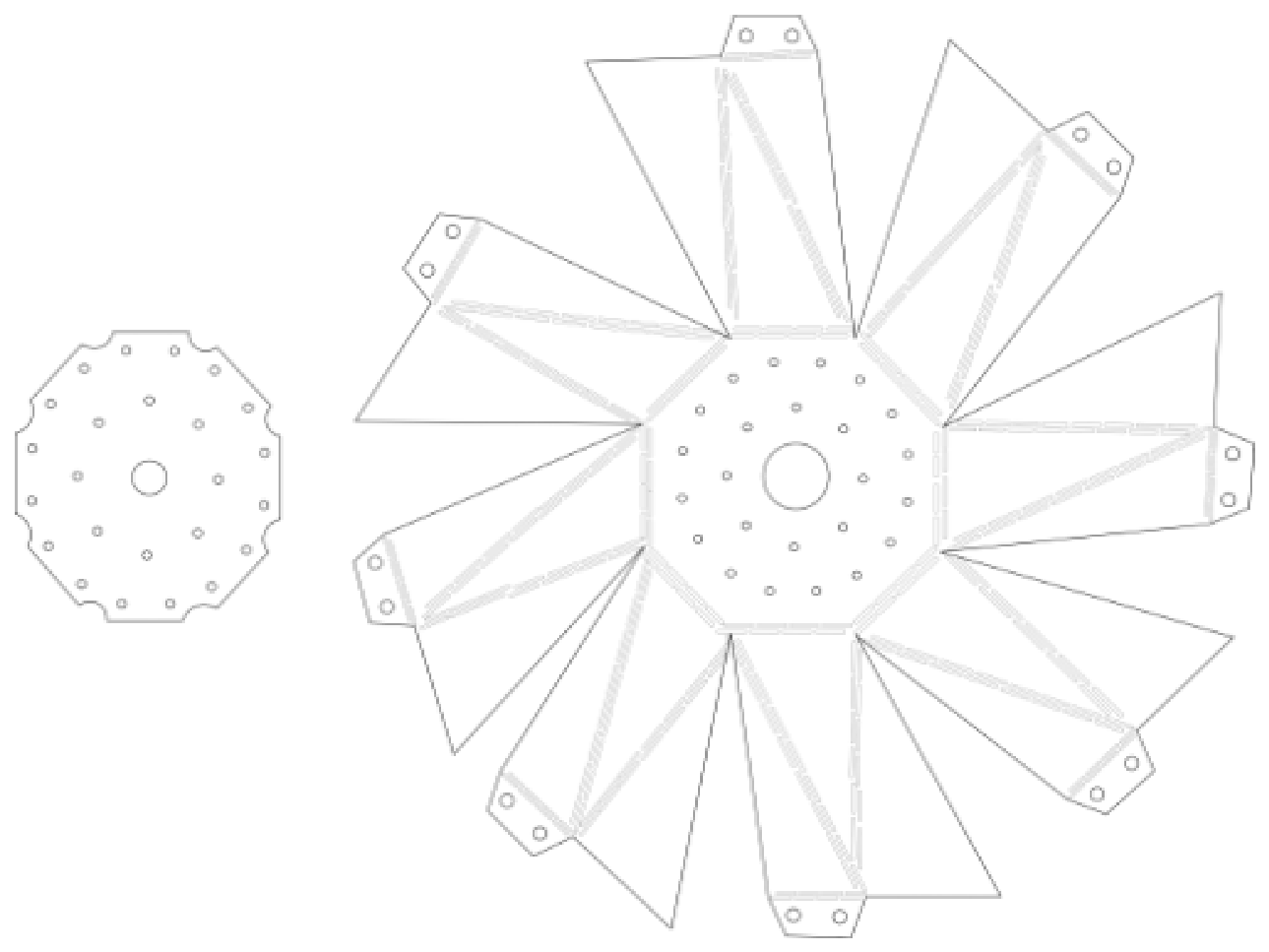
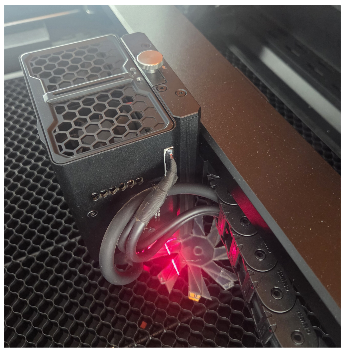
This section deals with the description of an antenna prototype based on four TCO segments and capable of assuming five different mechanical configurations that correspond to five different operative frequencies, which cover almost the entire UHF band. For the antenna prototype, a set of four bistable TCO elements is considered. Each TCO cell can assume two stable states, depleted or compressed, as described in Section 2. In particular, Figure 3 reports the CAD of a single TCO structure. The elements of the TCO cells were fabricated considering a plastic laminate coated with an aluminum metallization of 20 μm. The structure was obtained using an IR laser cutter (1.2 W) combined with a 20 W blue diode laser; the laser engraver’s resolution is 0.02 mm. Figure 4 shows the fabrication phase of a single TCO cell using a laser engraver. The TCO cell is assembled on a copper ground plane, and the two stable states are assessed. As it is an unbalanced antenna, due to the ground plane’s presence, no balun is required. In particular, the bistable states are shown in Figure 5a,b, respectively. Once fabricated, the four TCO cells are assembled to form the monopole structure. The main body of the monopole is hollow, and the actuators aim to change the state of the TCO cells that are inserted inside the hollow structure of the monopole. In particular, four micro-stepper electric engines are controlled by means of an ESP32 microcontroller and a ULN2003A driver (Espressif Shanghai China, Shanghai, China). To avoid the perturbation introduced by the actuators of the TCO cells, the stepper motors and the control circuits are embedded inside the TCO cells’ structure to create a perfect electromagnetic shield. The four TCO cells are connected and placed on a copper metallic ground plane. The feeding is provided with a subminiature type A coaxial connector (SMA). A photo of the four-element TCO cells’ monopole antenna is reported in Figure 6.

4. Numerical and Experimental Assessment

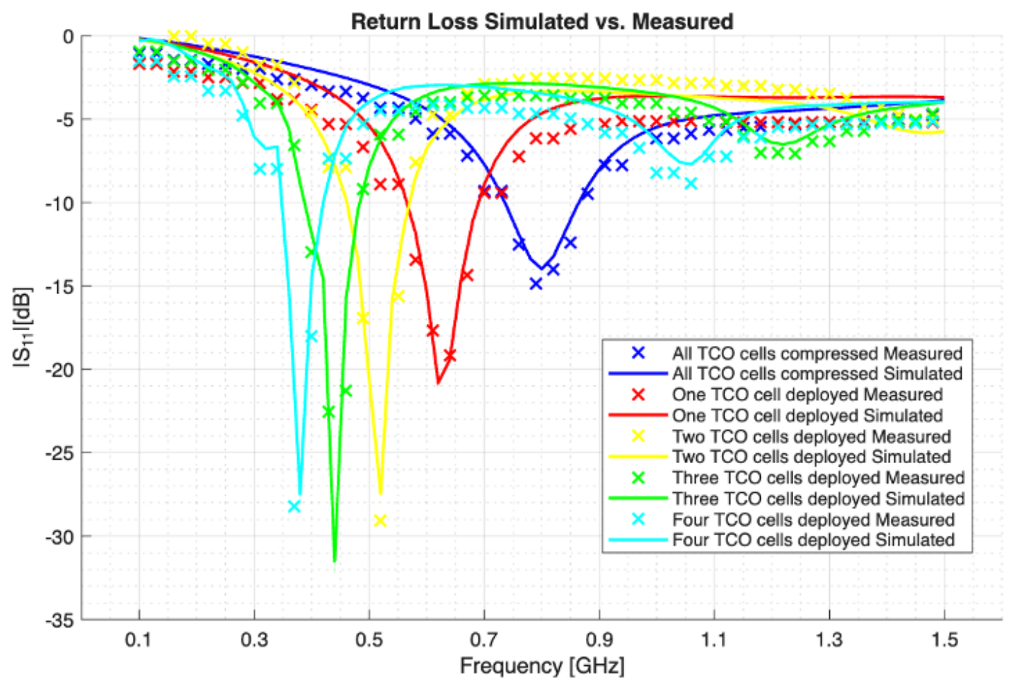
In this section, the TCO monopole antenna is numerically and experimentally assessed. The numerical data were obtained using ANSYS HFSS 2023 R1. The fabricated prototype was measured in an anechoic chamber for its reflection and radiation characteristics. The beam pattern in the different configurations was then collected along the E-plane with an angular step of 5 degrees. Figure 7 reports the simulated and measured reflection coefficient S 11 for all of the five TCO configurations. The agreement between simulated and measured data is quite good, and the S 11 remains well below −10 dB at the corresponding resonance frequency of the TCO configurations.
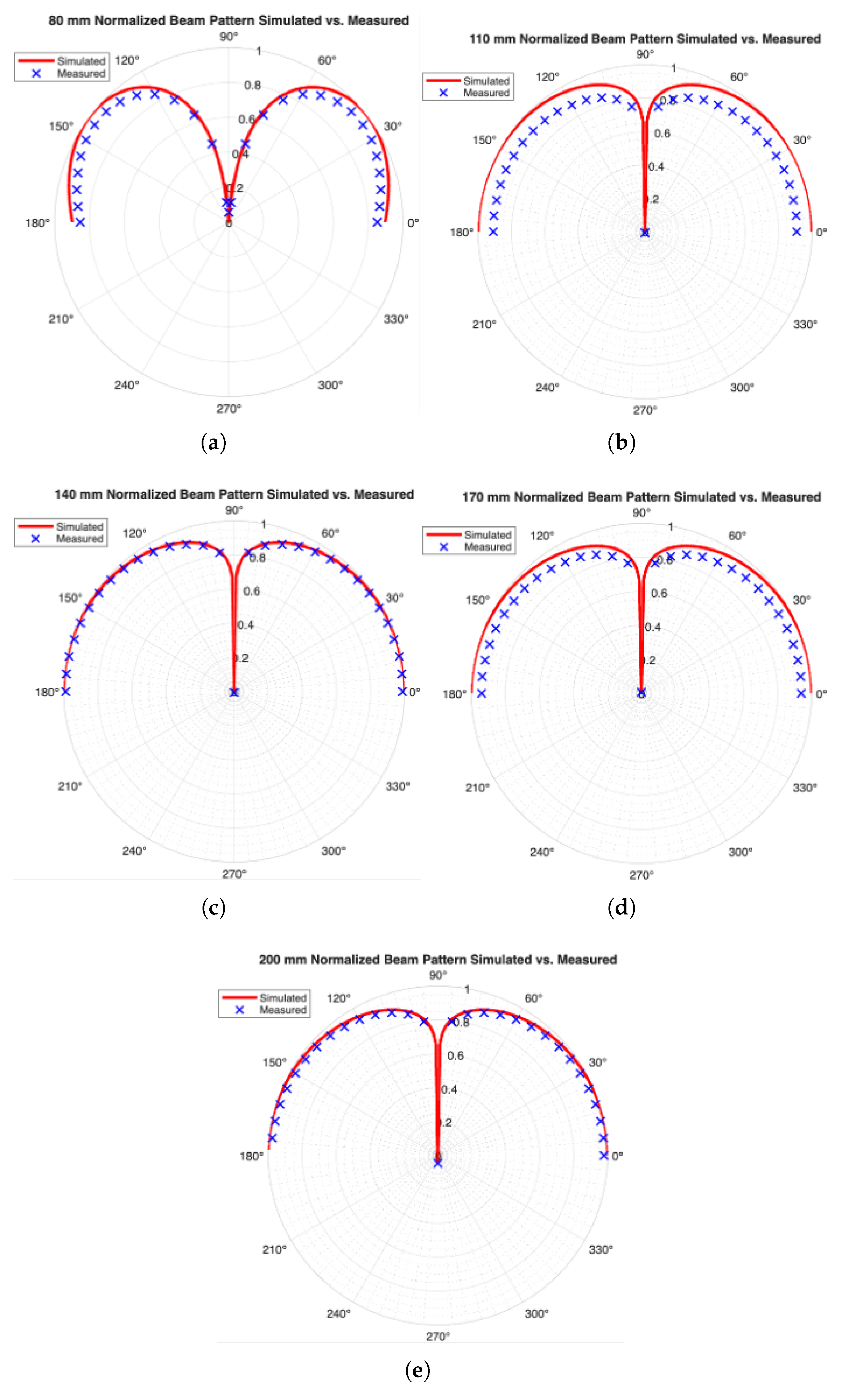
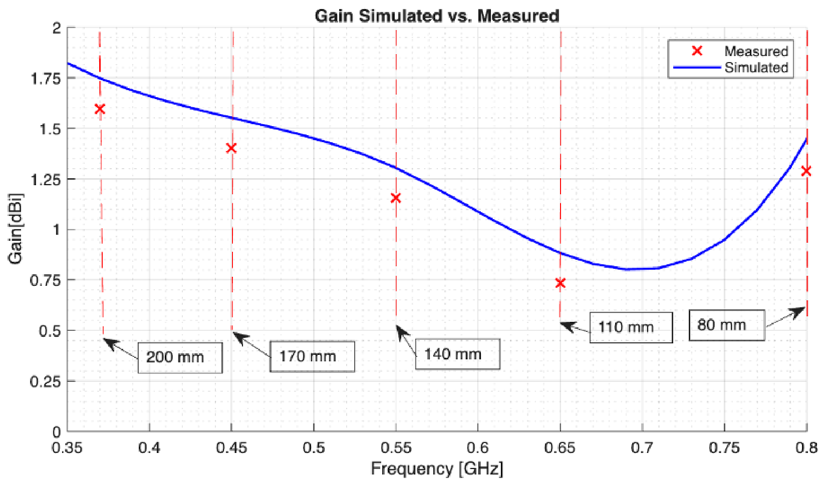
The comparisons between simulated and measured antenna beam patterns for the four TCO configurations are reported in Figure 8. The continuous lines represent the simulated data, while the crosses represent the measurements. The beam patterns were collected along the E-plane at ϕ = 90 , as the beam pattern along ϕ is isotropic. As can be noticed, the numerical and measured data are in good agreement. The beam patterns in the different TCO configurations present, as expected, a null in correspondence with the elevation angle θ = 90 (typical of a monopole antenna). The beam pattern is zero at θ > 180 due to the presence of the metallic ground plane. In Figure 9, the comparisons between the simulated and measured antenna gain are reported. The antenna gain in the different TCO configurations was measured using the well-known three-antennas method. The measurements differ from the synthetic data only by a small fraction of dBi. Certainly, due to the low gain, the proposed antenna is not suitable as a principal satellite antenna system, but it can be considered as an auxiliary system that can be activated in case of failure of the principal antenna. This is quite common in satellite design. However, it is worth noting that the obtained antenna gain is compatible with the gain of a standard monopole antenna, considering that variations of +/−1 dB during the gain measurements are quite common.

5. Conclusions

A reconfigurable monopole antenna based on a triangular cylindrical origami structure feeder is presented. The antenna structure can be efficiently compressed and then easily deployed at different electrical lengths by applying a simple solicitation by means of linear or rotational actuators, such as a small stepped motor. An antenna prototype was designed, fabricated, and numerically and experimentally assessed. The obtained experimental results were quite satisfactory, and they demonstrated the potentialities of multi-section TCOs, especially for satellite communication applications.

Author Contributions

Conceptualization, M.D., S.M. and V.M.; methodology, M.D., S.M. and V.M.; validation, V.M., S.M. and M.D.; writing—original draft preparation, M.D., S.M. and V.M.; writing—review and editing; supervision, M.D., S.M. and V.M. All authors have read and agreed to the published version of the manuscript.

Funding

This research received no external funding.

Data Availability Statement

Data is contained within the article.

Conflicts of Interest

The authors declare no conflicts of interest.

References

  1. Kitsuregawa, T. Advanced Technology in Satellite Communication Antennas: Electrical & Mechanical Design; Artech House: New York, NY, USA, 1990. [Google Scholar]
  2. Thornton, J.; Huang, K.-C. Modern Lens Antennas for Communications Engineering-MAJ; 1. Aufl; Wiley-IEEE Press: Hoboken, NJ, USA, 2012. [Google Scholar]
  3. Matin, M.A. (Ed.) Wideband, Multiband, and Smart Antenna Systems; Springer International Publishing: Berlin/Heidelberg, Germany, 2021. [Google Scholar] [CrossRef]
  4. Sharma, S.K.; Rao, S.; Shafai, L. (Eds.) Handbook of reflector antennas and feed systems. In Theory and Design of Reflectors; Artech House: New York, NY, USA, 2013; Volume 1. [Google Scholar]
  5. Turner, N.; Goodwine, B.; Sen, M. A review of origami applications in mechanical engineering. Proc. Inst. Mech. Eng. Part C J. Mech. Eng. Sci. 2016, 230, 2345–2362. [Google Scholar] [CrossRef]
  6. Meloni, M.; Cai, J.; Zhang, Q.; Sang-Hoon Lee, D.; Li, M.; Ma, R.; Parashkevov, T.E.; Feng, J. Engineering Origami: A Comprehensive Review of Recent Applications, Design Methods, and Tools. Adv. Sci. 2021, 8, 2000636. [Google Scholar] [CrossRef]
  7. Ahmed, A.R.; Gauntlett, O.C.; Camci-Unal, G. Origami-Inspired Approaches for Biomedical Applications. ACS Omega 2021, 6, 46–54. [Google Scholar] [CrossRef] [PubMed]
  8. Kaddour, A.-S.; Velez, C.A.; Georgakopoulos, S.V. A Deployable and Reconfigurable Origami Reflectarray Based on the Miura-Ori Pattern. In Proceedings of the 2020 IEEE International Symposium on Antennas and Propagation and North American Radio Science Meeting, Montreal, QC, Canada, 5–10 July 2020; pp. 91–92. [Google Scholar] [CrossRef]
  9. Li, R.; Zhou, G.; Luo, P.; Zhao, Z. Design of Planar Antenna and Space Deployable Mast Based on a New 8r Origami Mechanism. SSRN 2024. [Google Scholar] [CrossRef]
  10. Donelli, M.; Menon, S.; Mulloni, V.; Marchi, G.; Dal Chiele, I. Origami Fresnel Zone Plate Lens Reflector Antennas for Satellite Applications. Electronics 2025, 14, 3892. [Google Scholar] [CrossRef]
  11. Molaei, A.; Liu, C.; Felton, S.M.; Martinez-Lorenzo, J. Origami Inspired Reconfigurable Antenna for Wireless Communication Systems (Version 1). arXiv 2018, arXiv:1805.10370. [Google Scholar] [CrossRef]
  12. Lin, M.-H.; Lin, C.-C.; Lin, S.-M.; Chang, C.-C.; Lin, S.-C.; Wu, J.-W.; Chang, S.-F. Advanced Beam Reconfiguration in Horn Antennas Through Origami-Based Design. In Proceedings of the 2025 19th European Conference on Antennas and Propagation (EuCAP), Stockholm, Sweden, 30 March–4 April 2025; pp. 1–4. [Google Scholar] [CrossRef]
  13. Zhu, B.; Zhang, W.; Song, L. A Reconfigurable Beam-Scanning Origami Reflectarray Antenna. In Proceedings of the 2025 18th IEEE United Conference on Millimeter Waves and Terahertz Technologies (UCMMT), Nanjing, China, 25–28 August 2025; pp. 1–3. [Google Scholar] [CrossRef]
  14. Zhang, X.; Yan, N.; Luo, Y.; Ma, K. Pattern-Reconfigurable Circularly Polarized Multibeam Reflectarray Using a Height-Adjustable Origami Structure. In Proceedings of the 2025 IEEE MTT-S International Conference on Numerical Electromagnetic and Mul-tiphysics Modeling and Optimization (NEMO), Tianjin, China, 29 July–1 August 2025; pp. 1–3. [Google Scholar] [CrossRef]
  15. Anelli, F.; Loconsole, A.M.; Losito, R.; Prudenzano, F. Broadband Circularly Polarized Antenna Array via Metasurface and Partially Emptied Substrate. IEEE Access 2025, 13, 158316–158321. [Google Scholar] [CrossRef]
  16. Munawar, S. Reconfigurable Origami Antennas: A Review of the Existing Technology and its Future Prospects. Int. J. Wirel. Microw. Technol. 2020, 10, 34–38. [Google Scholar] [CrossRef]
  17. Shah, S.I.H.; Lim, S. Review on recent origami inspired antennas from microwave to terahertz regime. Mater. Des. 2021, 198, 109345. [Google Scholar] [CrossRef]
  18. Georgakopoulos, S.V.; Zekios, C.L.; Sattar-Kaddour, A.; Hamza, M.; Biswas, A.; Clark, B.; Ynchausti, C.; Howell, L.L.; Magleby, S.P.; Lang, R.J. Origami Antennas. IEEE Open J. Antennas Propag. 2021, 2, 1020–1043. [Google Scholar] [CrossRef]
  19. Yue, S. A Review of Origami-Based Deployable Structures in Aerospace Engineering. J. Phys. Conf. Ser. 2023, 2459, 012137. [Google Scholar] [CrossRef]
  20. Tang, P.; Li, X.; Yang, Y.; Khawale, R.P.; Chen, H.; Wang, Z.; Filipov, E. Design and Simulation of Origami-Inspired Multifunctional Waveguide Devices. In Proceedings of the 2025 International Applied Computational Electromagnetics Society Symposium (ACES), Orlando, FL, USA, 18–21 May 2025; pp. 1–2. [Google Scholar] [CrossRef]
  21. Fei, Z.; Xu, D.; Zhao, Y.; Han, Z.; Song, L.; Ma, R.; Guo, Y. From the Yoshimura origami pattern to foldable structures: Exploration of crease design. Thin-Walled Struct. 2025, 209, 112888. [Google Scholar] [CrossRef]
  22. Njogu, P.M.; Sanz-Izquierdo, B.; Jun, S.Y.; Kalman, G.; Gao, S.; Malas, A.; Gibbons, G.J. Evaluation of Planar Inkjet-Printed Antennas on a Low-Cost Origami Flapping Robot. IEEE Access 2020, 8, 164103–164113. [Google Scholar] [CrossRef]
  23. Biswas, A.; Zekios, C.L.; Georgakopoulos, S.V. A Dual-Band Origami FSS. In Proceedings of the 2019 IEEE International Symposium on Antennas and Propagation and USNC-URSI Radio Science Meeting, Atlanta, GA, USA, 7–12 July 2019; pp. 2023–2024. [Google Scholar] [CrossRef]
  24. Commisso, J.; Folkers, M.; Murphey, T. Spiral Wrapped Antenna Technology. In Proceedings of the 2025 IEEE Aerospace Conference, Big Sky, MT, USA, 1–8 March 2025; pp. 1–8. [Google Scholar] [CrossRef]
  25. Yasuda, H.; Tachi, T.; Lee, M.; Yang, J. Origami-based tunable truss structures for non-volatile mechanical memory operation. Nat. Commun. 2017, 8, 962. [Google Scholar] [CrossRef] [PubMed]
  26. Yasuda, H.; Yamaguchi, K.; Miyazawa, Y.; Wiebe, R.; Raney, J.R.; Yang, J. Data-driven prediction and analysis of chaotic origami dynamics. Commun. Phys. 2020, 3, 168. [Google Scholar] [CrossRef]
  27. Chang, D.; Harrison, C.; Aronson, E. Tubular monopole of arbitrary dimensions: The radiation field. IEEE Trans. Antennas Propag. 1969, 17, 534–540. [Google Scholar] [CrossRef]
Figure 1. Behavior of the single triangular cylindrical origami cell.
Electronics 15 02914 g001
Figure 2. Structure of the four TCO cells’ monopole antenna.
Electronics 15 02914 g002
Figure 3. CAD of a single TCO cell structure.
Electronics 15 02914 g003
Figure 4. Photo of the fabrication process of a single TCO cell with the laser engraver.
Electronics 15 02914 g004
Figure 5. Photo of a single TCO cell in compressed (a) and deployed states (b), respectively.
Electronics 15 02914 g005
Figure 6. Photo of the four TCO cells’ monopole antenna placed on the metallic ground plane. All the TCO cells are deployed.
Electronics 15 02914 g006
Figure 7. Antenna return loss for the different configurations. Simulated vs. measured data.
Electronics 15 02914 g007
Figure 8. E-plane beam patterns for the different TCO configurations. Simulated vs. measured data.
Electronics 15 02914 g008
Figure 9. Antenna gain for the different TCO configurations. Simulated vs. measured data.
Electronics 15 02914 g009
Table 1. Antenna TCO geometrical configurations.
Number of Deployed TCO CellsElectric Length (m)Resonant Frequ. (MHz)
00.08900
10.11700
20.14550
30.17450
40.20350
Disclaimer/Publisher’s Note: The statements, opinions and data contained in all publications are solely those of the individual author(s) and contributor(s) and not of MDPI and/or the editor(s). MDPI and/or the editor(s) disclaim responsibility for any injury to people or property resulting from any ideas, methods, instructions or products referred to in the content.