Article

5G-TSN Integrated Prototype for Reliable Industrial Communication Using Frame Replication and Elimination for Reliability

1
Fraunhofer Institute for Production Technology IPT, 52074 Aachen, Germany
2
Ericsson GmbH, Ericsson Allee 1, 52134 Herzogenrath, Germany
3
Moxa Inc., 13F., No. 3, Sec. 4, New Taipei Blvd., Xinzhuang Dist., New Taipei City 242, Taiwan
4
WZL|RWTH Aachen University, 52074 Aachen, Germany
*
Author to whom correspondence should be addressed.
Electronics 2025, 14(4), 758; https://doi.org/10.3390/electronics14040758
Submission received: 28 November 2024 / Revised: 29 January 2025 / Accepted: 11 February 2025 / Published: 15 February 2025
(This article belongs to the Special Issue 5G and Beyond Technologies in Smart Manufacturing, 2nd Edition)

Abstract

:
The stringent requirements of industrial communication, especially high reliability and real-time response, are regarded as the main bottlenecks for the widespread adoption of wireless technologies in industrial applications. The integration of 5G and Time-Sensitive Networking (TSN) protocols offers convergence of both wireless and various wired communication technologies for industrial applications. In this article, we describe our 5G and TSN integrated prototype, which achieves high reliability based on the IEEE 802.1CB Frame Replication and Elimination for Reliability (FRER) scheme. Different 5G systems have been used in various combinations to empirically study the benefits of FRER for 5G communication in real industrial environments. We evaluate the performance of our prototype and validate it for an industrial use case on Smart Sensors for Milling Processes, requiring a latency below 10 ms for 99.99% of the packets sent, which has been achieved in the measurements using FRER. This use case and the high requirements towards latency and reliability demonstrate the benefits of 5G integration with FRER for industrial production.

1. Introduction

Industrial production traditionally relies on wired solutions for communication among machines, controllers, and sensors. There are certainly benefits of using wired communication, such as high reliability, low latency, large data rates, and wireless interference-free operation. However, wired technologies lack the flexibility and scalability aspects desired in several industrial applications, which wireless solutions can offer. While wireless technology has traditionally shown limitations on reliability, data rates and timeliness aspects, 5G technology especially with Ultra-Reliable and Low Latency communication (URLLC) features and its integration with Time-Sensitive Networking (TSN) or Deterministic Networking (DetNet), tends to overcome these deficiencies [1,2,3,4], enabling a large range of use cases such as autonomous guided vehicles to remote control and monitoring of machines and actuators [5,6,7,8]. The usage of smart wireless sensors especially offers a lot of potential for industrial manufacturing, for example, in the context of condition monitoring, process monitoring, and control [9,10,11,12]. They offer an easy-to-use retrofitting solution, providing real-time insights of the machining process, monitoring a wide range of parameters such as vibration, acoustic emission, temperature, or humidity, enables to gather process insights detecting anomalies or signs of tool wear, to interact with the process, and to achieve higher efficiency, quality and lifetime of resources [13,14,15].
Closed-loop applications interacting with safety and control systems have high requirements for the communication infrastructure to avoid costly downtime or injuries. Wireless communication may suffer from outages and packet losses due to propagation losses and interference. The 5G protocol stack is designed to overcome successful packet reception errors through error control mechanisms. When packets need to be retransmitted as part of the error control mechanisms, these lead to higher transmission latencies. In this paper, we analyze the requirements for smart sensor use cases to see if 5G and TSN can meet the requirements [16,17,18]. For such analysis, a 5G and TSN prototype is being implemented, supporting Frame Replication and Elimination for Reliability (FRER) to increase the availability and reliability of the communication [19,20]. This prototype evaluates the impact of FRER on the communication performance for three different 5G setups combined with a wired network supporting different TSN standards.
For this purpose, the paper is structured as follows: Section 2 describes the use of smart sensors for milling processes in industrial manufacturing and their requirements for wireless communication. Pointing out the high relevance of reliable and stable communication for industrial production. In Section 3, prototype architecture and implementation are given. Different setups are described, combining different frequency spectrums and 5G systems to investigate the use of FRER for reliable and resilient 5G transmission. The detailed performance measurements carried out on the integrated prototype system for the use case requirements and a discussion of the results are presented in Section 4. Section 5 summarizes the paper and provides an outlook.

2. Wireless Sensors for Industrial Manufacturing

To achieve high-quality manufacturing processes, such as the milling of highly complex components, fast detection of deviations in the movement of the milling tool and a subsequent reaction within a few milliseconds are critical. Machine-integrated sensors can record process data and send this information to the machine’s controller. Applications involving advanced data analytics and real-time condition monitoring require cloud-based systems. Due to the complex machining process, with a lot of movement of workpieces and work tools, having a wired sensor system is impractical as wires can restrict motion, risk entanglement, and are prone to wear or damage in such dynamic environments. The current wireless options, such as 4G or Wi-Fi, do not provide the low latency, reliability, or bandwidth needed for industrial applications. Such industrial communication needs high reliability and a low latency wireless connection [15,16]. This article investigates a use case for anomaly detection for milling processes using intelligent sensor systems. The use case was designed to support benchmarking the suitability of 5G and FRER integration for industrial applications.

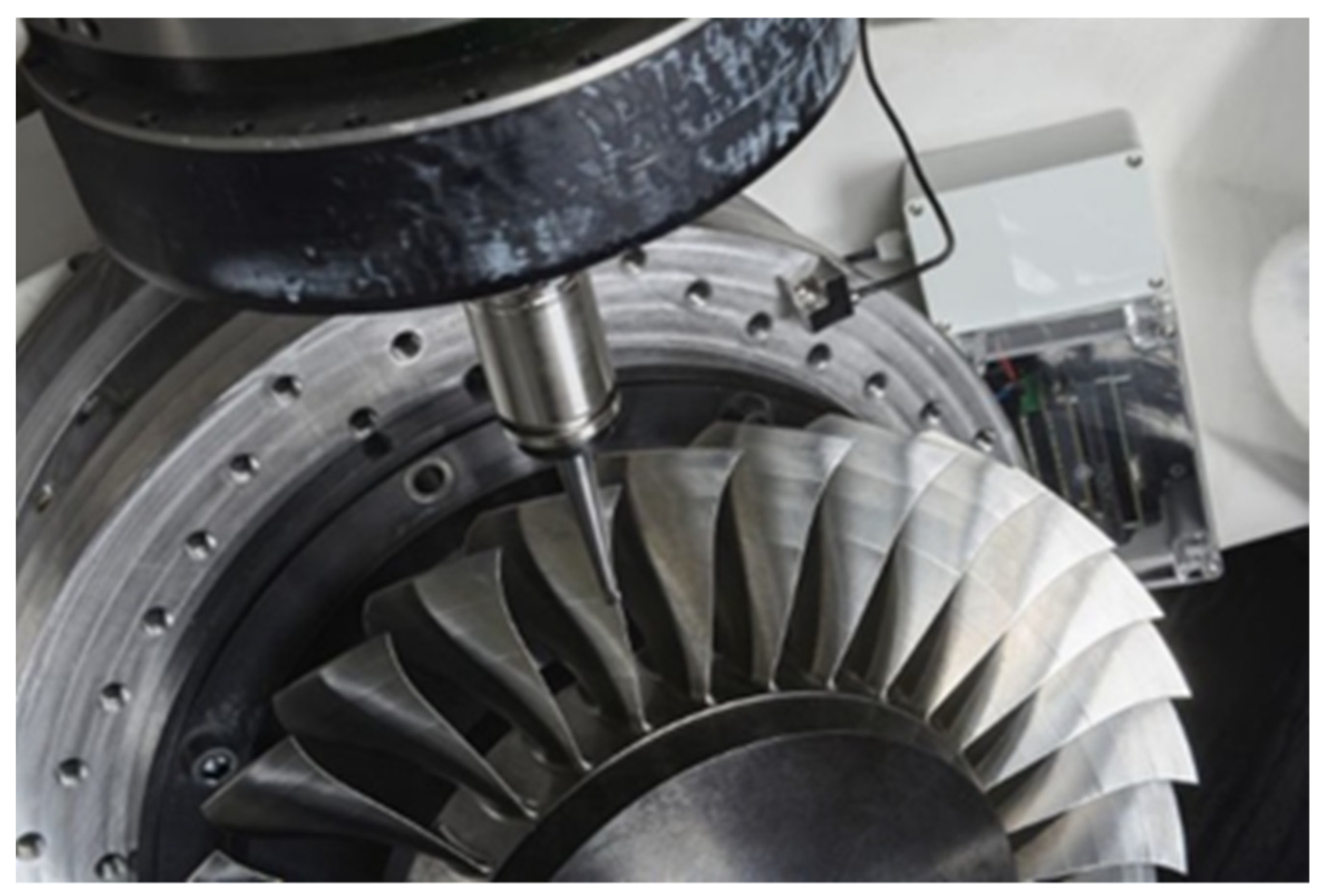
2.1. Tool Wear Detection

In a milling process, the quality of the tool determines the quality of the final surface finish of the product. However, the tool tends to wear down during the process, requiring additional work to reach the desired results. In some cases, tool chipping or breakage occurs, creating undesirable surface defects that are hard to restore. These tool chippings arise due to factors such as excessive load or forced action on the tool’s thermal crackdown during the process. These factors are unpredictable and need to be monitored. In rare instances, a tool may collide with the workpiece, damaging both. These tool collisions may occur due to a variety of reasons, such as deviation from the software model and the actual geometry of the workpiece and improper locking of the tool or the workpiece.
To prevent these disturbances from occurring during the production process, the machine controller application must continuously monitor the condition of the tool in real time and react to the condition change by adapting process parameters such as the spindle speed or exchanging the tool before it is worn out. A vision-based analysis is impractical since the milling application is complex, with the tool mounted with the spindle. The other option is to analyze the Acoustic Emissions generated by the tool interacting with the workpiece. These acoustic waves differ from regular vibration waves with a higher frequency range, from 10 kHz to 900 kHz. The acoustic wave induced by the tool has a spectral characteristic that differs depending on the condition of the tool. Thus, based on the changes in the spectral characteristics, it is possible to detect the condition of the tool. These waves are sensed by the so-called Acoustic Emission sensors, which are integrated directly into the workpiece, as shown in Figure 1.
The analog data are then sampled at very high frequencies, typically around 1 MHz, generating large amounts of data. These data are pre-processed for the spectral component and transmitted as a data packet. These data packets must be reliably transmitted in real time as the data packets contain the critical tool condition for the application controller to react to the changes. Due to the complex nature of the manufacturing process, with many movable parts, a wired solution using cables is not practical here since the cable needs to be considered in the process planning, increasing complexity and slowing it down. The 5G-enabled smart sensor and control with 5G are shown in Figure 2.
A smart sensor platform with a high-speed analog-to-digital converter (ADC) is used to digitalize the AE sensor signals that are to be transmitted. These digitalized data are then preprocessed within the Field Programmable Gate Array (FPGA) to extract the necessary features, such as the Frequency spectrum of the detected wave, while simultaneously providing data suppression. The extracted features are packed in a UDP data packet and transmitted to the machine controller. The machine controller comprises an edge device and a PLC. The data from the sensor are processed with respect to the machine data in the edge devices. Based on the analysis, control signals are generated and sent to the PLC. The PLC then controls the machine, creating a closed-loop system from the sensor to the machine.

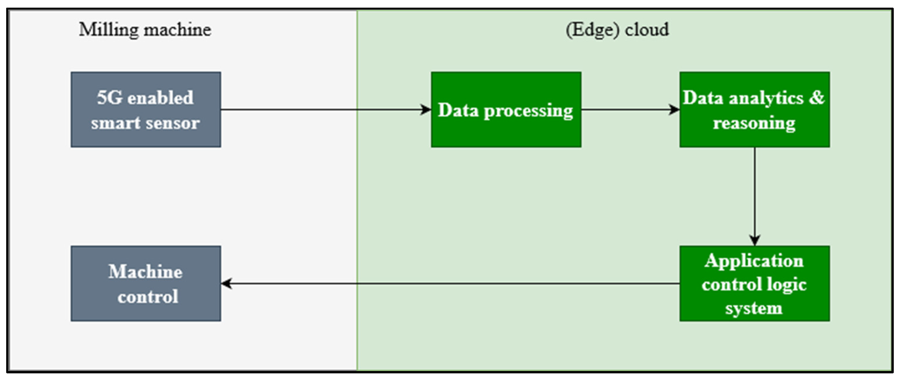
2.2. Communication Requirements of the Smart Sensors for Milling Processes Use Case

Using wireless smart sensors for monitoring milling processes enables a variety of use cases, such as collision detection, tool wear estimation, and tool breakage detection. Due to the criticality of the events that require to be detected, the requirements towards the data transmission from the sensor system are high. In Table 1, the industrial communication requirements for a high-precision milling process are given. Similar values can be found in the literature, varying depending on the specific use case [21,22,23]. These reference values will form the basis for the evaluation of the prototype.

3. 5G and TSN Integrated Prototype for Resilience and High Reliability

In this article, we describe the details of our 5G and TSN integrated prototype. Our integrated prototype includes 5G systems based on the 3GPP Release 15 operating in the mid-band frequency range of 3.7–3.8 GHz and 5G mmW system operating at 26 GHz besides a 5G pre-commercial system using the URLLC features specified in the 3GPP Release 16/17 operating in 28 GHz. Our integrated prototype is based on the commercial TSN switches supporting TSN protocols such as IEEE 802.1CB and IEEE 802.1Qbv. In this work, we focus on reliability enhancements for 5G using the Frame Replication and Elimination for Reliability (FRER) scheme based on IEEE 802.1CB.

3.1. 5G Non-Public Network on the Industrial Shopfloor

5G wireless communication is becoming highly important in smart manufacturing and enabling the digitization of industries [24]. We have conducted over-the-air (OTA) evaluation tests on three different types of 5G systems integrated with the FRER scheme on the Fraunhofer IPT shop floor.

3.1.1. 5G Mid-Band System Operating in 3.7–3.8 GHz

The 5G non-public network operates in the 3.7–3.8 GHz (5G n78 band) locally licensed industrial spectrum with 100 MHz of system bandwidth. Having multiple radio units at various locations on the ceiling provides excellent coverage in the whole factory hall of area ca. 3000 m2. The mid-band spectrum has very good propagation characteristics, including for non-line of sight connectivity. We have used Qualcomm x55 modem chipset-based terminal devices in our tests on this system.

3.1.2. 5G mmW System Deployment at 26 GHz

The 5G mmW non-public network operates at 26 GHz (5G n258 band) using a system bandwidth of 800 MHz. The 5G mmW system is well-suited for applications with high data rate demands and requiring low mobility. The mmW frequencies are prone to high path loss, and hence, directivity gains with narrow beamwidths are used. We used Qualcomm ×65-based devices in our OTA tests.

3.1.3. 5G URLLC Test System

The 5G URLLC (ultra-reliable low latency communication) system used in our experimental evaluation on the shopfloor is a standard compliant pre-commercial standalone test system. The 5G URLLC test system is configured to operate in 28 GHz (n261 5G band) with 200 MHz of system bandwidth. The 5G URLLC test system leverages various 3GPP Rel. 15/16/17 specifications on reliability enhancements and low latency [25]. Moreover, the 5G URLLC test system supports features such as Ethernet PDU sessions, Ethernet header compression, over-the-air (OTA) time synchronization, traffic classification, prioritization, and QoS mapping to allow easy integration with TSN protocols as specified by 3GPP [26,27]. We used a test 5G URLLC UE for our experiments on the shop floor.
The choice of 5G system operating frequencies in the sub-6 GHz and the mmW ranges is mainly attributed to the availability of frequency spectrum for industrial use and the industrial use-case deployment conditions. In Germany, the 3.7–3.8 GHz frequency range has been allocated by the Federal Spectrum Regulatory Authority (BNetzA) for local industrial use. Similarly, the 26 GHz range is available for non-public network deployments. The two frequency ranges have significantly different propagation characteristics, and their use depends upon the specific requirements of the industrial application and its deployment conditions. Most notably, the sub-6 GHz range shows, in general, better propagation characteristics compared to the mmW frequencies and is not as prone to blockage and penetration loss. mmW frequency range, on the other hand, has a significantly large available bandwidth that is well-suited for data-intensive applications. However, due to beamforming, these may require additional measures for non-LOS and beyond LOS propagation [28] and may not be well-suited to applications involving high mobility.

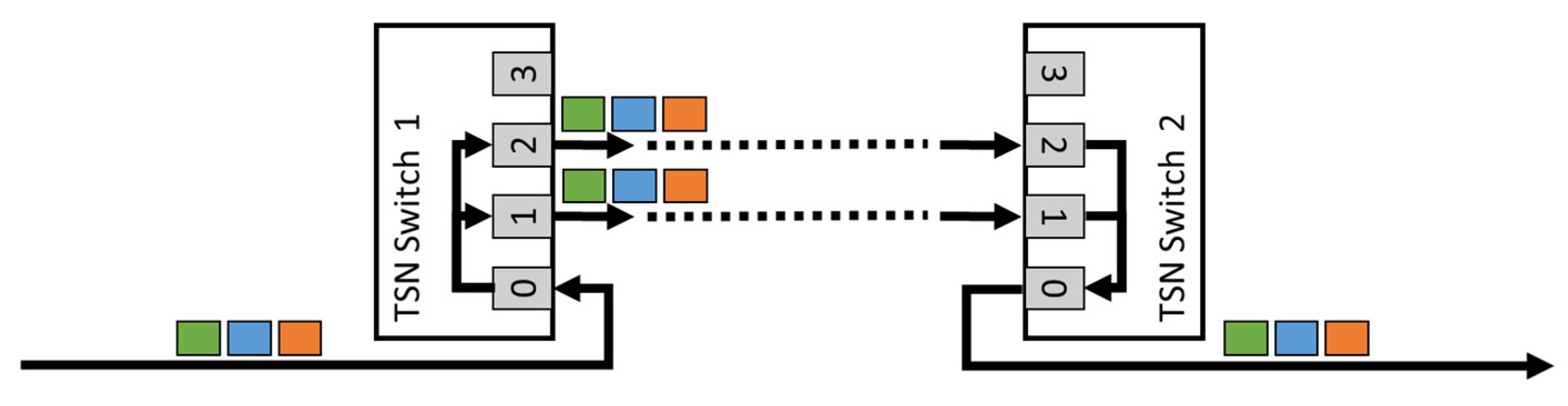
3.2. Setup of the Time-Sensitive Networking Environment

TSN is a set of IEEE standards aimed at enhancing Ethernet to support time-critical applications in industrial and automotive environments [29,30]. TSN aims at four different functions: Time synchronization, high availability and reliability, bounded latency, and resource management. Part of the set is IEEE 802.1CB-FRER [31], a standard that provides redundancy and fault tolerance in Ethernet networks by sending replicated frames and eliminating any redundant copies of the frame to enhance communication reliability as shown in Figure 3. To integrate the 5G mid-band deployment and the 5G mmW system deployment in the TSN network, a layer 2 to layer 3 tunnel has been used. The 5G URLLC testbed supports layer 2 traffic natively.

3.3. 5G-Industry Campus Europe in Aachen

The measurements have been carried out on the shop floor of the Fraunhofer IPT at the 5G-Industry Campus Europe (5G-ICE) in Aachen. The research infrastructure of the 5G-Industry Campus Europe covers around one square kilometer of the Melaten Campus of RWTH Aachen and a total of 7000 square meters of shopfloor and thus offers a large area for research into various industrial application scenarios such as cloud-based control, smart sensors, or logistics. The shop floor of the Fraunhofer IPT offers on 2.700 m2 shopfloor a large variety of machining tools and a real production environment. In Figure 4, the shop floor and the measurement setup are shown. It consists of different network data recorders that store the data packages with synchronized time stamps to alter the calculation of the jitter and latency. These data recorders are connected to the sender, the receiver, the switches, and the 5G-UEs.

3.4. Overall Architecture and Measurement Setup

Due to wireless channel outages, it may occur that all transmitted packets are not decoded correctly in the initial transmission attempt. The 5G protocol stack has an error control mechanism that detects and retransmits the incorrectly received packets. Moreover, variable delays in 5G communication may occur due to processing, signaling in the protocol stack, alignment with transmit opportunity, etc. The use of FRER with replicating data frames to be sent over multiple paths over 5G enhances reliability and helps in reducing packet delay variations as a side-effect. In this article, we evaluate five different setups using FRER to achieve the needed reliability for the use case.

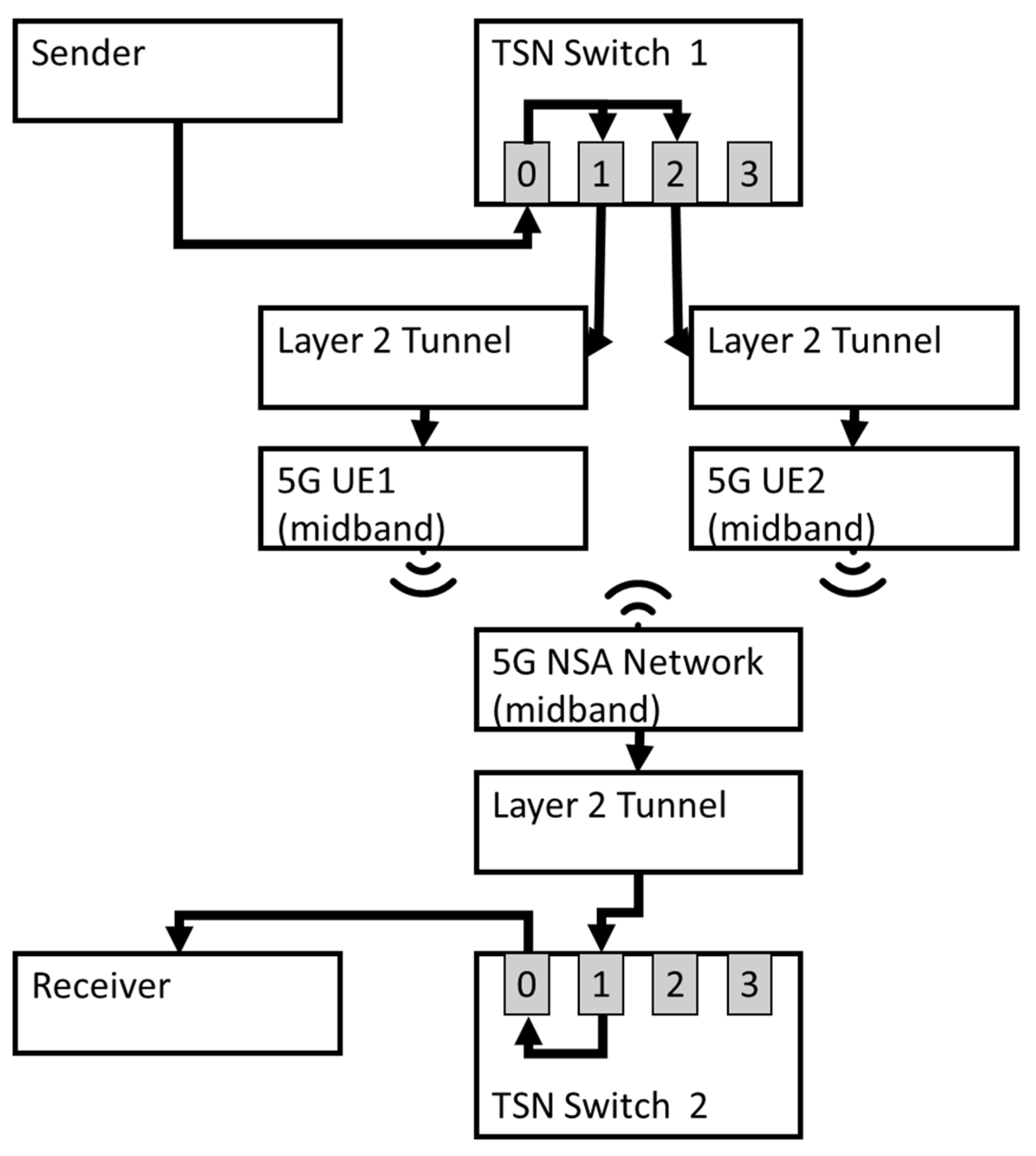
3.4.1. Setup 1: Using FRER for Redundant Transmissions on the Same 5G Mid-Band System

In production use cases, the use of a 5G system on an industrial shop floor, especially operating in mid-band (sub 6 GHz) frequencies, is becoming common. In Setup 1, as shown in Figure 5, we investigate the use of FRER when packets are replicated on multiple UEs belonging to the same network. As shown in Figure 4, data are transmitted via a TSN network integrated with the 5G system towards the receiver end. Please note that in our evaluation, we consider the sender and receiver endpoints on a PC with emulated data transmissions from the Milling Machine use case as described in Section 2. The data arrive from the sender to Switch 1 and is replicated and sent via Ports 1 and 2, sent via two different 5G-end devices to the 5G mid-band system using one core, and finally to Switch 2, which forwards only the first copy of the packet and discards any replicated copies of the packet. The timestamps of the data are measured after the replication and before the elimination to evaluate the effects of an increase in reliability for the 5G transmissions. The wireless propagation causes occasional link outages, which are rectified by the hybrid automatic repeat request (HARQ) retransmission scheme and via radio link control (RLC) retransmission mechanism in the 5G protocol stack [25]. The error control mechanisms mentioned above induce extra delays. The likelihood that errors are induced at the same time on multiple independent links using FRER is significantly reduced; thereby, an increase in reliability of the 5G transmissions is observed. Please note that the setup described above shows only the uplink transmissions. The same setup has also been used for downlink transmissions.

3.4.2. Setup 2: Redundant Transmissions Using FRER via Different 5G Mid-Band Systems

In Setup 2, as shown in Figure 6, we investigate the use of FRER using not one mid-band system as in Setup 1 but one for each replicated data packet. This creates a redundancy not only on the UE side but also on the network side. After replication in Switch 1, one packet is sent via a non-standalone (NSA) 5G system, and one packet is sent via a standalone (SA) 5G system. As in Setup 1, in Switch 2, only the first copy of the packet will be forwarded, and any redundant copy arriving later is discarded.

3.4.3. Setup 3: Redundant Transmissions via 5G URLLC Test System and 5G Mid-Band System

In Setup 2, the goal is to investigate what benefit FRER offers when different 5G systems are used. Therefore, the replicated data sent from Switch 1 will be sent parallel via the Release 15 mid-band system and the URLLC testbed to Switch 2 for elimination, as shown in Figure 7. The timestamps of the data were measured after replication and before elimination to determine the increase in the reliability of the 5G transmission. Please note that the URLLC test system natively supports Ethernet PDU sessions, and therefore, support for tunnel is not needed.

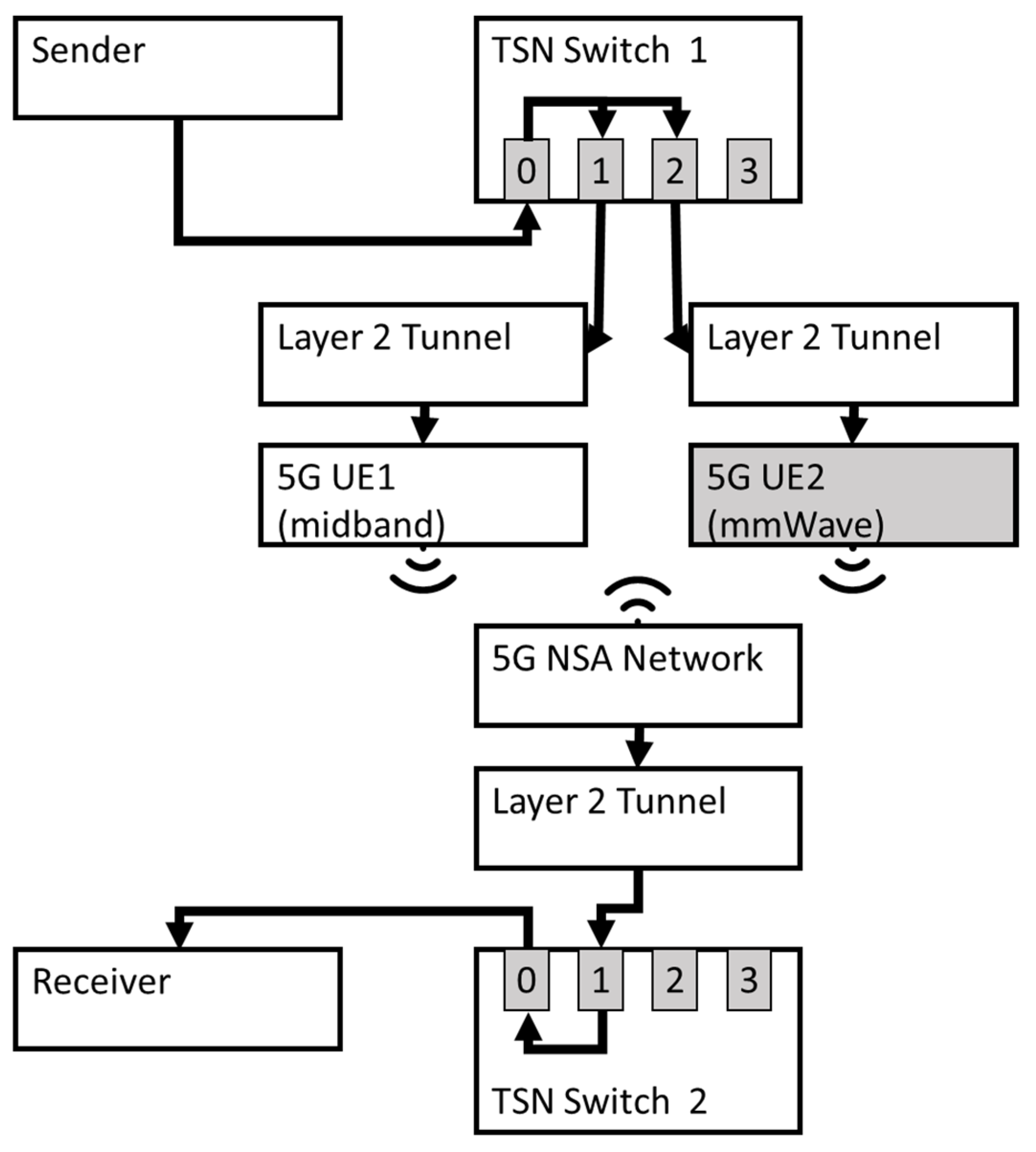
3.4.4. Setup 4: Redundant Transmission via 5G Mid-Band and 5G mmW Systems Sharing the Same Core Network

We investigated the use of two 5G systems operating in different frequencies. In particular, we use FRER-based redundancy for 5G systems operating in the 3.7–3.8 GHz (5G n78 band) and the 26 GHz (5G n258 band), as shown in Setup 4. Please note that in this setup, the two non-standalone 5G systems share the same core network. The replicated data sent from Switch 1 are sent in parallel via the Release 15 mid-band and 5G mmW systems, as shown in Figure 8. The timestamps of the data were measured after replication and before elimination to determine the reliability and packet delay variations in the 5G transmissions.

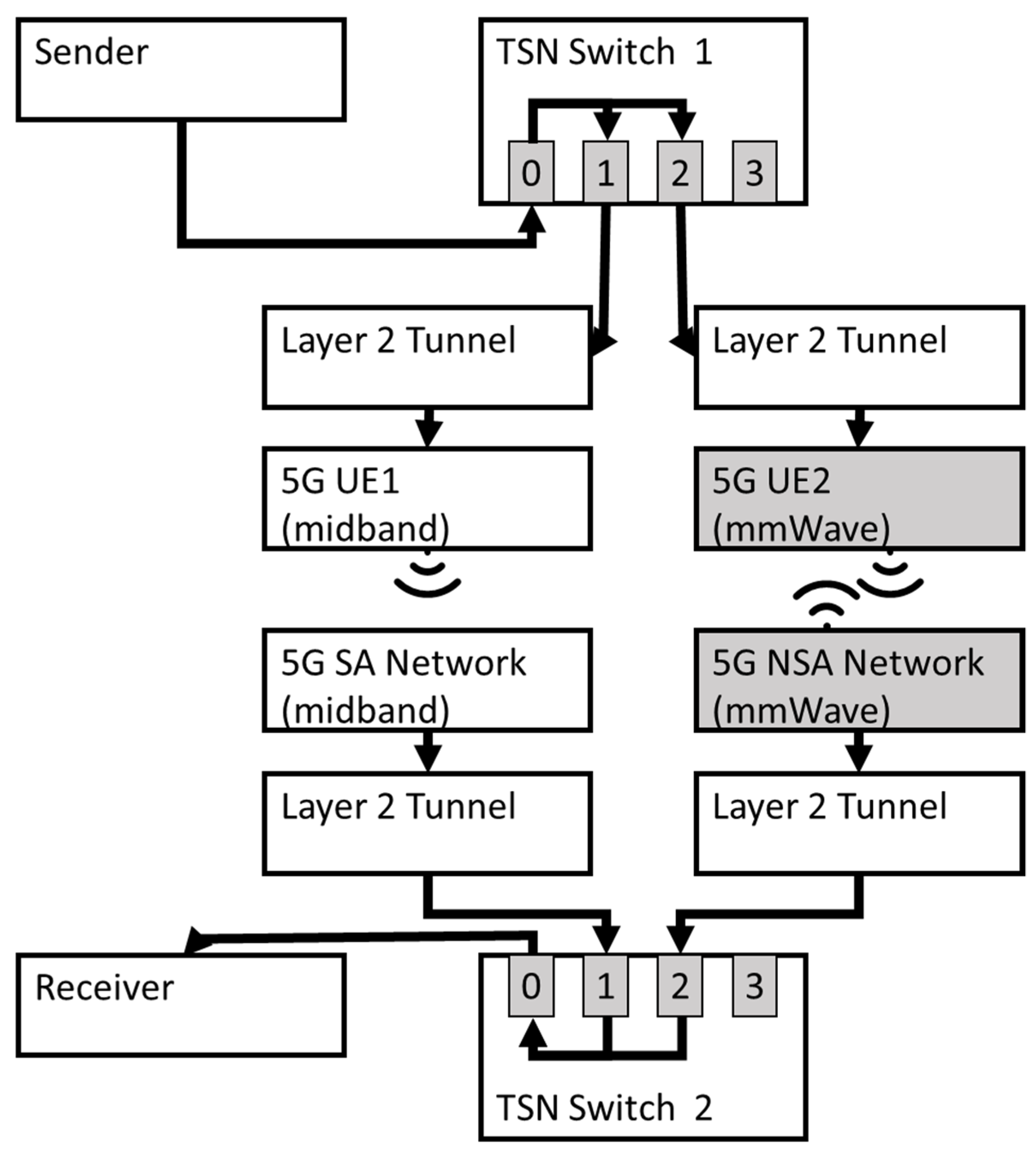
3.4.5. Setup 5: Redundant Transmission via 5G Mid-Band and 5G mmW Systems

In this setup, we use two different 5G networks operating in the 3.7–3.8 GHz (5G n78 band) and the 26 GHz (5G n258 band). Please note that compared to Setup 4, we have complete 5G system redundancy with independent core networks. The replicated data sent from Switch 1 are transmitted in parallel via 5G mid-band and 5G mmW systems, as shown in Figure 9. The timestamps of the data were measured after replication and before elimination operations.

4. Performance Results and Discussion

In this section, we describe the evaluation results on the reliability aspects in the three setups (cf. Section 3) with and without using FRER. All the measurements were conducted on an industrial shop floor to validate the use case prototype in a production environment. The tests have been performed with a 100-byte message size and a cycle time of 10 ms.

4.1. Evaluation of Setup 1: Using FRER for Redundant Transmissions in the Same 5G Mid-Band System

The results of Setup 1, using two mid-band connections and one core, are shown in Figure 10. The end-to-end latency of the individual UEs one and two are given in Figure 10a,b as a distribution over time. In Table 2, the performance results can be seen: UE1 with a mean latency of 6.39 ms and UE2 with 6.40 ms. The combined transmission after elimination on Switch 2 is shown in Figure 10c, with an average latency of 6.11 ms. By using FRER, the maximum latency for 99.99% of the values has dropped from 11.16 ms for UE1 and 10.95 for UE2 to 8.28 ms, meeting the use case requirements set to 10 ms for the 99.99th percentile value. The reduction of the latency can be explained by observations made in Figure 10. First, the distribution of the latency values for the individual UEs is much broader, and for the FRER-enabled pipeline, it is much more compact around the mean value. Furthermore, Figure 10a,b show outliers in the latency of up to 60 ms. These outliers can only be seen for the individual UE but not in the overall latency diagram. The use of replicated, parallel data streams smoothens the latency distribution and, therefore, the overall jitter of the communication. Larger spikes and outliers are eliminated.
As a result of Setup 1, the use of FRER improves the reliability of 5G transmissions. An interesting side effect of the improved reliability is the reduction of latency. Since FRER always selects the fastest packet to be transmitted, a path affected by disturbances such as hybrid automated repeat request re-transmissions (HARQ reTx), scheduling and processing delays, or UE internal delays will not affect the overall transmission. Further, it can be seen that the impact of using FRER in the same network enables a reliable transmission suitable for the described use case.

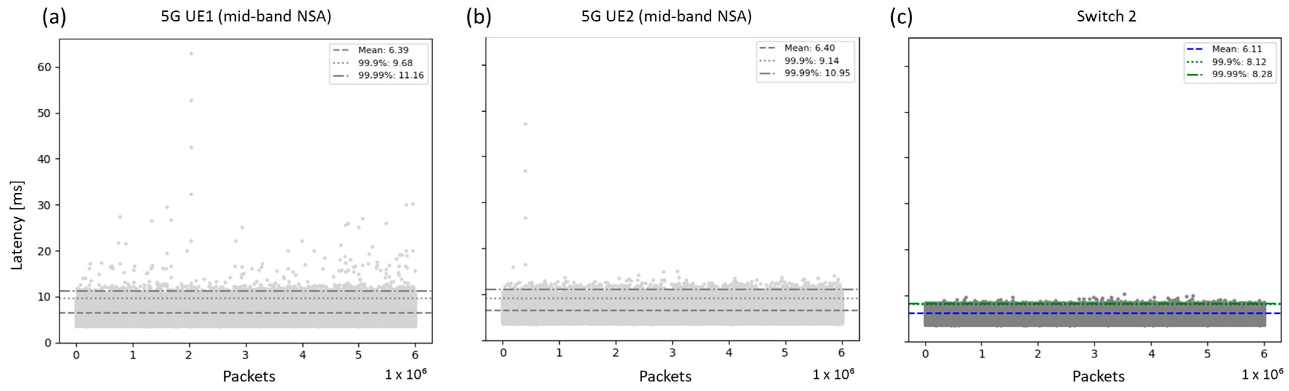
4.2. Evaluation of Setup 2: Redundant Transmissions Using FRER via Different 5G Mid-Band Systems

The results of Setup 2, using two different 5G mid-band systems, are shown in Figure 11. The end-to-end latency of the individual UEs one and two are given in Figure 11a,b as a distribution over time. The combined transmission after elimination on Switch 2 is shown in Figure 11c, with an average latency of 6.08 ms. By using FRER, the maximum latency for 99.99% of the values has dropped from 11.31 ms for UE1 and 11.10 for UE2 to 8.23 ms, again meeting the use case requirements set to 10 ms for 99.99% of messages. As in Setup 1, different outliers have been equalized by the second communication path, smoothening the overall latency and reducing the jitter of the communication. Especially, the communication via UE1 shows different spikes going up to 60 ms compared to fewer spikes in the communication of UE1. Still, UE2 could deliver packets in time to Switch 2 when a latency spike occurred in UE1, achieving an overall stable and reliable communication. Further, it can be seen in Figure 11c that the few smaller spikes left in the communication of Setup 1 could be eliminated in Setup 2. This can be explained by the increased redundancy due to the different 5G systems used. Latency spikes coming for the network were smoothed in Setup 2, where the spike only affected one communication path, whereas latency spikes in the network affected both communication paths in Setup 1.
As a result of Setup 2, the impact of FRER using redundant 5G systems can be seen. Again, the spikes of the different communication paths could be equalized using the redundant communication paths. Further, an improvement in communication quality could be achieved by using redundancy not only in end devices but also in the 5G system.

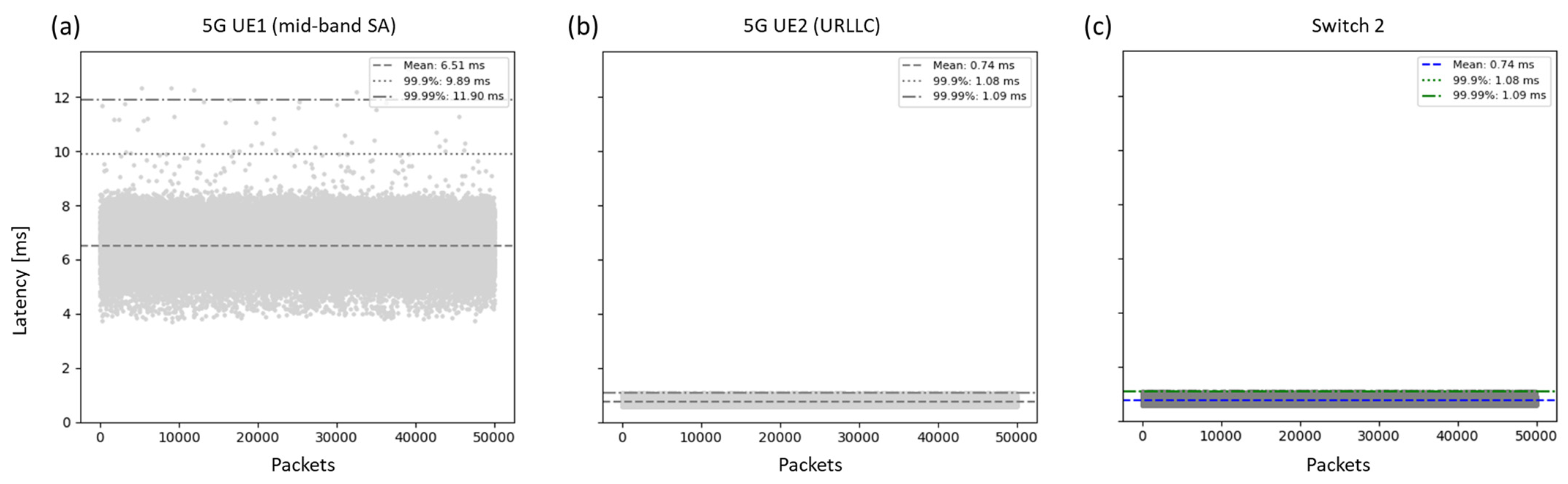
4.3. Evaluation of Setup 3: 5G URLLC Test System and 5G Mid-Band System

The results of Setup 3, using one 5G mid-band and one 5G mmW connection, are shown in Figure 12. The end-to-end latency of the individual UEs one and two are given in Figure 12a,b as a distribution over time. UE1 with a mean latency of 6.51 ms and UE2 with 0.72 ms. The combined transmission after elimination on Switch 2 is shown in Figure 12c, with an average latency of 0.72 ms. The mean latency and the 99.99% value for the overall pipeline are the same as for the URLLC values, the same as the latency over time diagram shown in Figure 12c. Since the URLLC has much shorter transmission times than the mid-band deployment, the messages always arrive earlier than the messages from UE1. Therefore, the messages from router 1 are always eliminated and have no impact on the overall performance of the setup. Only if there are packet losses in the URLLC testbed is the mid-band message not eliminated.
As a result of Setup 3, FRER has a large impact if being used for systems with similar performance but has almost no impact if systems with different performances are used. The low latency and high reliability of the URLLC testbed are outperforming the 5G mid-band system, therefore making the frame replication obsolete.

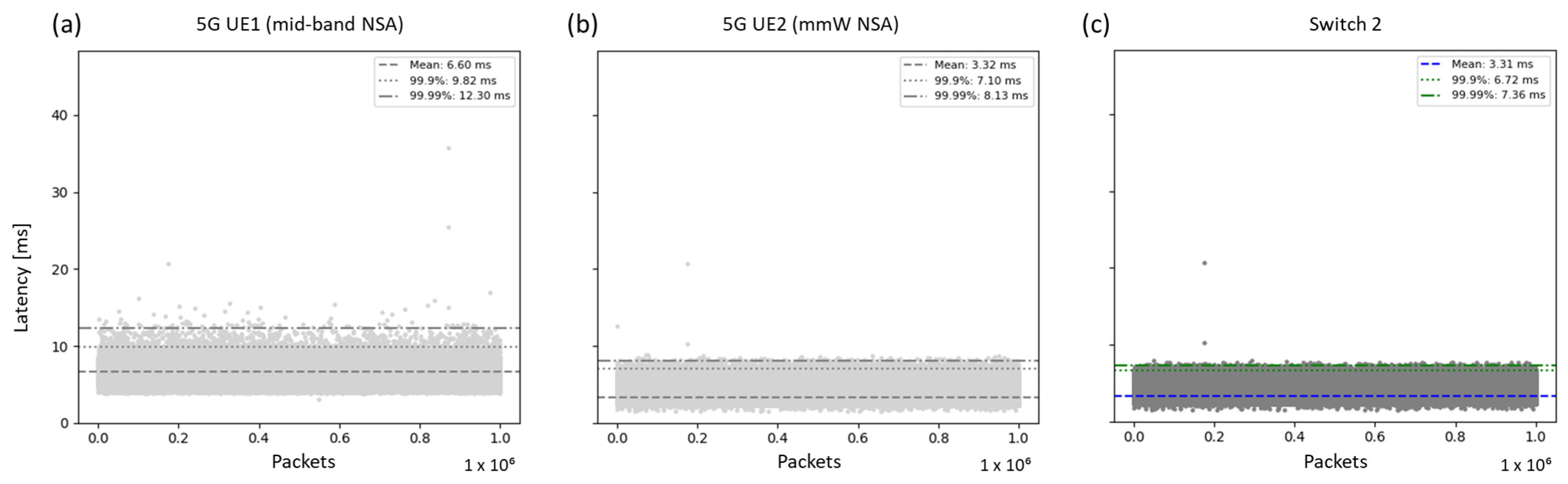
4.4. Evaluation of Setup 4: Redundant Transmission via 5G Mid-Band Deployment and 5G mmW System Deployment

The results of Setup 4, using one mid-band and one mmW connection, are shown in Figure 13. The end-to-end latency of the individual UEs one and two are given in Figure 13a,b as a distribution over time. UE1 with a mean latency of 6.60 ms and UE2 with 3.32 ms. The combined transmission after elimination on Switch 2 is shown in Figure 13c, with an average latency of 3.31 ms. Again, the mmW system has a shorter transmission time than the mid-band deployment. Therefore, the messages arrive earlier than the messages from UE1. The mid-band system is only used to equalize spikes occurring in the mmW transmission, reducing the mean latency and jitter compared to the sole mmW performance. This has a high impact on the 99.99% values, which dropped from 12.30 ms for UE1 and 8.13 ms for UE2 to 7.36 ms. However, this equalization can only happen if the latency spike is not caused by the 5G system, which is shared by both communication streams.
As a result of Setup 4, FRER has a limited impact if used for systems with different performances. Since the mmW system has a higher performance than the mid-band system, the mid-band system is used as the primary communication path only in the case of a latency spike.

4.5. Evaluation of Setup 4 with Introduced Disturbances: Redundant Transmission via 5G Mid-Band Deployment and 5G mmW System Deployment

To further evaluate the benefit of FRER for 5G communication, a second measurement using Setup 4 has been performed. This time, disturbances, in the form of a metal plate put in front of the antennas of UE2, have been introduced. The metal plate blocking the transmission partly simulates a workpiece or a metal housing of the milling machine blocking partly the signal. Outside the machine, this blocking can be caused by a crane, an autonomous guided vehicle (AGV), or a metal workpiece passing or being placed in front of the UE. Especially in industrial environments, a lot of metal components are moved and used; therefore, the use case is highly relevant for communication systems in industrial environments. The results of Setup 4 with introduced disturbances, using one 5G mid-band and one 5G mmW connection, are shown in Figure 14. The end-to-end latency of the individual UEs one and two are given in Figure 14a,b as a distribution over time. It can be seen how the performance of the mmW system drops when a metal plate is put in front of the UE, blocking the line of sight to the 5G base station radio unit. In Figure 14, the performance results can be seen: UE1 with a mean latency of 6.76 ms and UE2 with 4.13 ms. The mean latency of UE2 is much higher than in the previous trial due to the spikes in latency caused by the metal plate. The combined transmission after elimination on Switch 2 is shown in Figure 14c. The primary communication path changes when the mmW system is slowed down by the introduced interference, and the mid-band system takes over. As a result, despite the mmW system’s high average latency of 4.13 ms, the overall system has the lowest average latency of all three measured values with 3.47 ms and a latency of 9.24 ms for 99.99% of the messages meeting the use case requirements despite the introduced disturbances. Further, due to the introduced disturbances, six packets were not transmitted via the mmW system during the measurements, whereas in Switch 2, no packet loss could be identified. Again, the mid-band system has been used as the primary transmission path, equalizing the overall performance.
As a result of Setup 4 with introduced disturbances, FRER has a large impact if being used in harsh environments with a lot of metal or large components being moved around. The overall pipeline achieved the lowest mean latency and could avoid packet loss using the mid-band system as a temporal primary communication path. Therefore, it can be observed that FRER can enhance communication reliability on industrial shop floors with radio propagation suffering from strong multipath, blockage, etc.

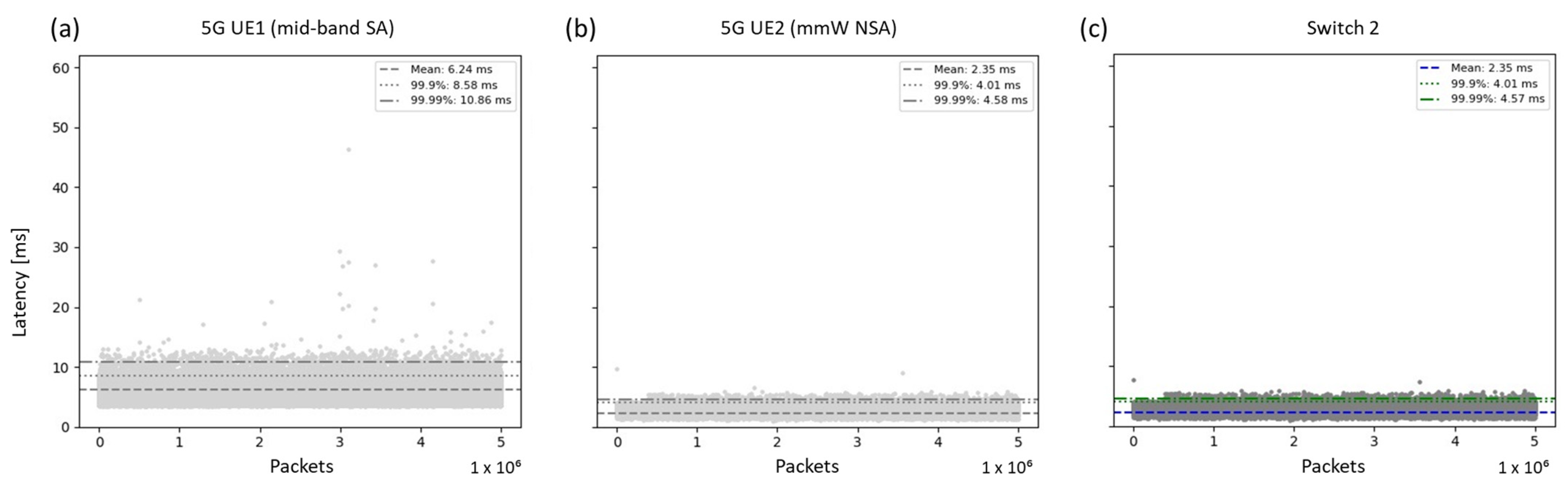
4.6. Evaluation of Setup 5: Redundant Transmission via 5G Mid-Band and 5G mmW Systems

The results of Setup 5, using one mid-band and one mmW system, are shown in Figure 15. The end-to-end latency of the individual UEs, one and two, are given in Figure 15a,b as a distribution over time. UE1 with a mean latency of 6.24 ms and UE2 with 2.35 ms. The combined transmission after elimination on Switch 2 is shown in Figure 15c, with an average latency of 2.35 ms. With the shorter transmission time of the mmW system compared to the mid-band system, the impact of FRER is very limited. Similar to Setup 4, it can be seen that different spikes in the mmW plot have been equalized by the mid-band system. Further, compared to Setup 4, no latency spike could be detected in all three plots. Due to the very high degree of redundancy, there was no shared resource that could create a latency spike accruing in both communication paths.

4.7. Evaluation of the Results Regarding the Smart Sensor Use Case

In Section 2, the Smart Sensors for Milling Processes use case has been discussed, motivating the utilization of 5G in combination with FRER for achieving reliable communication. Aside from this specific use case, highly reliable communication plays an important role in industrial communication. Data from wireless smart sensors or interconnected actuators in production can be used in a variety of cases. The communication requirements in Section 2 focus on use cases with a latency below 10 ms, a high reliability of 99.99%, and a data size between 128 and 1024 bytes.
Table 2, an overview of the measurement results related to the use case requirements discussed in Section 2, is given. The industrial use-case requirements are met every time FRER is used, underlining its impact on communication reliability. In Setup 1 and Setup 2, it has been shown that the reduction of outliers in the communication caused by disturbances in one of the communication paths increases the reliability of the system and reduces the overall jitter and latency. Both setups meet the use case requirements when using FRER but do not meet the requirements with one single communication path. As shown in Table 2. Setup 1 achieved a latency of 8.28 ms using FRER and only 11.16 ms and 10.95 ms for the single path communication. Aside from the overall improvement of the communication quality, it can be seen that some single paths also meet the communication requirements, but with larger spikes in communication, for example, Path 2 in Setup 4 and Setup 5. The only path meeting the communication requirements without spikes is the URLLC test system used in Setup 3. Further, the advantages of FRER in challenging industrial environments for radio signal propagation with moving objects and metal housings can be seen in Setup 4 with introduced disturbances. Having line of sight, Path 2 meets the industrial requirements in Setup 4, but as soon as disturbances due to blockage occur, the overall reliability is seen to be compromised, and the communication needs to rely on Path 1 to maintain reliable communication. Using FRER, the resilience of the communication regarding external influences such as the blocking of an antenna by a crane, metal housing, or a passing AGV has been increased, and so has the reliability. Such external disturbances can occur in industrial environments, especially for moving systems such as the wireless sensor mounted on a workpiece or tool inside a machine chamber or a moving object such as a crane or forklift.
Overall, it has been shown that the requirements for the Smart Sensors for Milling Processes use case could be met using 5G and FRER even in environments with challenging radio propagation conditions on an industrial shop floor. Using single communication may be vulnerable to wireless communication-related disturbances. These may cause undesirable outliers, which lead to unmet reliability targets for the use case. Using both paths in parallel creates resilience towards those disturbances, increasing reliability. The requirements of the Smart Sensors for Milling Processes use cases, having 10 ms latency for 99.99% of messages is a common value for a number of industrial use cases. Fieldbus protocols such as PROFINET [32] have similar requirements; for example, PROFINET RT (Real Time), used for data exchanged directly via the Ethernet protocol, is used to implement applications in which the cycle times are in the >10 ms range [33,34]. While redundancy is costly in terms of extra hardware and spectrum usage for a wireless system, the benefits in terms of increased reliability become essential in many industrial applications as we have empirically evaluated for the investigated Smart Sensors for Milling Processes use case.
The results of the measurements show, on the one hand, an increased reliability of the communication using the redundant paths. On the other side, the setups used show the different needs for more hardware and spectral resources when using various configurations. Whereas TSN networks typically incorporate multiple switches and redundant paths, 5G networks offer limited redundancy between the end device and the core network. Therefore, the use of FRER creates different setups that necessitate additional hardware. Thus, the choice of network architecture and level of redundancy directly influences the hardware needed and, therefore, the costs for the infrastructure.

5. Conclusions and Outlook

This article presents a 5G and TSN integrated prototype based on the IEEE 802.1CB Frame Replication and Elimination for Reliability (FRER) scheme. The prototype has been empirically evaluated for a Smart Sensors for Milling Processes use case. The use case demands highly reliable wireless communication for online monitoring and cloud-based decision-making, which warrants the use of a 5G communication system. While wired communication is not an option in this use case, there is also a need for continuously monitoring the condition of the tool in real-time and reacting accordingly to the condition of the tool, for instance, by adapting machining parameters such as the spindle speed or even exchanging the tool before it is worn out. In industrial environments with challenging radio propagation conditions, 5G communication may undergo packet delay variations, which become undesirable for use cases with reliable low latency communication demands. In this work, we have evaluated the use of redundant paths via FRER implemented on commercial off-the-shelf TSN switches. We have empirically studied the use of redundant 5G paths on the same as well as different 5G systems operating in both 3.7–3.8 GHz and 26 GHz frequency ranges. Our experimental results indicate that while redundant paths require additional hardware and spectral resources, the likelihood of redundant paths concurrently undergoing communication anomalies due to radio propagation and other factors is very rare. The results obtained for the different setups indicate that FRER is very useful in meeting the low latency and high reliability target of the investigated tool condition monitoring use-case with the requirement of lower latency with a 99.99 percentile. Especially with introduced disturbances, FRER greatly improves the reliability in communication in harsh environments such as industrial production. The use of redundant transmission enhances the robustness of communication in the event of a failure and reduces latency and communication behavior. Overall, it can be seen that the usage of FRER enables reliable communication within the requirements set by the industrial use case, which is not the case for most single communication paths. Further, it has been discussed how the requirements described, 10 ms for 99.99% of all packets, are highly relevant for industrial communication.
Thus, redundancy enabled by FRER for 5G communication has been shown to meet the demanding communication reliability and latency targets of the Smart Sensors for Milling Processes use-case even for the challenging radio propagation conditions on an industrial shop floor. All the empirical results in this work have been obtained in a real production environment with various 5G systems. We have obtained a large measurement sample size (typically a few million samples) for each experimental test to ensure the high statistical significance of the presented empirical results in this article. Except for the 5G URLLC test system, all the results have been obtained on commercially available equipment, including a 5G network, 5G UEs, and FRER-enabled TSN switches. With these results, future use cases benefiting from reliable wireless communication can be implemented. The integration of 5G-FRER in real scenarios using fieldbus protocols could be one possible future work. Further investigating the impact of FRER on the connectivity of moving devices, for example, on an AGV, would bring further insights. This signifies the applicability of our detailed test results and analysis in today’s industrial use cases. We believe that the test results and their analysis in this article provide valuable insights to researchers and engineers aiming to apply deterministic 5G communication in mission-critical use cases.

Author Contributions

Conceptualization and validation, P.E.K. and J.A.; methodology, software, formal analysis and research, P.E.K., J.A., M.L., P.M., C.-C.L. and J.-L.Y.; writing—original draft preparation, P.E.K., J.A., P.M., C.-C.L. and J.-L.Y.; supervision, R.H.S. All authors have read and agreed to the published version of the manuscript.

Funding

Parts of this research were funded by the EU project TARGET-X. The TARGET-X project has received funding from the Smart Networks and Services Joint Undertaking (SNS JU) under the European Union’s Horizon Europe research and innovation program under Grant Agreement No: 101096614. Parts of this work have been funded by the German Federal Office for Information Security (BSI) under project funding reference numbers 01MO23016A, 01MO23016B, 01MO23016C, 01MO23016D, and 01MO23016G (5G-Sierra). The authors are responsible for the content of this publication.

Data Availability Statement

The original contributions presented in this study are included in the article. Further inquiries can be directed to the corresponding author.

Conflicts of Interest

Author Junaid Ansari was employed by the company Ericsson GmbH. Authors Chi-Chuan (Eric) Liu and Jun-Lin (Larry) Yeh were employed by the company Moxa Inc. The remaining authors declare that the research was conducted in the absence of any commercial or financial relationships that could be construed as a potential conflict of interest.

References

  1. Larranaga, A.; Lucas-Estan, M.C.; Martinez, I.; Val, I.; Gozalvez, J. Analysis of 5G-TSN Integration to Support Industry 4.0. In Proceedings of the 25th IEEE International Conference on Emerging Technologies and Factory Automation (ETFA), Vienna, Austria, 8–11 September 2020. [Google Scholar]
  2. Gundall, M.; Huber, C.; Rost, P.; Halfmann, R.; Schotten, H.D. Integration of 5G with TSN as Prerequisite for a Highly Flexible Future Industrial Automation: Time Synchronization based on IEEE 802.1AS. In Proceedings of the 46th Annual Conference of the IEEE Industrial Electronics Society, Singapore, 18–21 October 2020. [Google Scholar]
  3. Abuibaid, M.; Ghorab, A.; Saruhan, A.A.; St-Hilaire, M.; Parsons, G.; Farkas, J.; Varga, B.; Moldován, I.; Máté, M.; Naqvi, S.H.R. Integration of DetNet/TSN Reliability Functions in 5G Systems: A Case Study and Measurements. In Proceedings of the IEEE Conference on Standards for Communications and Networking (CSCN), Munich, Germany, 6–8 November 2023. [Google Scholar]
  4. Ulbricht, M.; Senk, S.; Nazari, H.K.; Liu, H.-H.; Reisslein, M.; Nguyen, G.T.; Fitzek, F.H.P. TSN-FlexTest: Flexible TSN Measurement Testbed. IEEE Trans. Netw. Serv. Manag. 2024, 21, 1387–1402. [Google Scholar] [CrossRef]
  5. Kehl, P.; Ansari, J.; Jafari, M.H.; Becker, P.; Sachs, J.; König, N.; Göppert, A.; Schmitt, R.H. Prototype of 5G Integrated with TSN for Edge-Controlled Mobile Robotics. Electronics 2022, 11, 1666. [Google Scholar] [CrossRef]
  6. Ansari, J.; Hsiao, T.-s.; Jafari, M.H.; Varga, B.; Farkas, J.; Moldovan, I.; Goppert, A.; Schmitt, R.H. 5G enabled flexible lineless assembly systems with edge cloud controlled mobile robots. In Proceedings of the IEEE Annual International Symposium on Personal, Indoor and Mobile Radio Communications (PIMRC), Kyoto, Japan, 12–15 September 2022. [Google Scholar]
  7. Baumann, D.; Mager, F.; Wetzker, U.; Thiele, L.; Zimmerling, M.; Trimpe, S. Wireless Control for Smart Manufacturing: Recent Approaches and Open Challenges. Proc. IEEE 2021, 109, 441–467. [Google Scholar] [CrossRef]
  8. Deshpande, Y.; Diederich, P.; Luthfi, M.; Becker, L.; Fontalvo-Hernández, J.; Kellerer, W. Integrating Deterministic Networking with 5G. arXiv 2024, arXiv:2409.13400v1. [Google Scholar]
  9. Ramamurthy, H.; Prabhu, B.S.; Gadh, R.; Madni, A.M. Smart Sensor Platform for Industrial Monitoring and Control. In Proceedings of the IEEE Sensors, Irvine, CA, USA, 31 October 2005; pp. 1116–1119, ISBN 0-7803-9056-3. [Google Scholar]
  10. Chuang, S.-M.; Chen, C.-S.; Wu, E.H. Implementation of Non-intrusive Intelligent Sensor System and 5G Edge Computing Gateway for Smart Factory. In Proceedings of the IEEE 4th Eurasia Conference on IOT, Communication and Engineering (ECICE), Yunlin, Taiwan, 28–30 October 2022. [Google Scholar]
  11. Ostasevicius, V.; Karpavicius, P.; Jurenas, V.; Cepenas, M.; Cesnavicius, R.; Eidukynas, D. Development of universal wireless sensor node for tool condition monitoring in milling. Int. J. Adv. Manuf. Technol. 2020, 110, 1015–1025. [Google Scholar] [CrossRef]
  12. Aponte-Luis, J.; Gómez-Galán, J.A.; Gómez-Bravo, F.; Sánchez-Raya, M.; Alcina-Espigado, J.; Teixido-Rovira, P.M. An Efficient Wireless Sensor Network for Industrial Monitoring and Control. Sensors 2018, 18, 182. [Google Scholar] [CrossRef] [PubMed]
  13. Zhang, C.; Yao, X.; Zhang, J.; Jin, H. Tool Condition Monitoring and Remaining Useful Life Prognostic Based on a Wireless Sensor in Dry Milling Operations. Sensors 2016, 16, 795. [Google Scholar] [CrossRef] [PubMed]
  14. Mohamed, A.; Hassan, M.; M’Saoubi, R.; Attia, H. Tool Condition Monitoring for High-Performance Machining Systems-A Review. Sensors 2022, 22, 2206. [Google Scholar] [CrossRef] [PubMed]
  15. Xie, Z.; Li, J.; Lu, Y. An integrated wireless vibration sensing tool holder for milling tool condition monitoring. Int. J. Adv. Manuf. Technol. 2018, 95, 2885–2896. [Google Scholar] [CrossRef]
  16. Muzaffar, R.; Ahmed, M.; Sisinni, E.; Sauter, T.; Bernhard, H.-P. 5G Deployment Models and Configuration Choices for Industrial Cyber-Physical Systems—A State of Art Overview. Trans. Ind. Cyber-Phys. Syst. 2023, 1, 236–256. [Google Scholar] [CrossRef]
  17. Wang, D.; Sun, T. Leveraging 5G TSN in V2X Communication for Cloud Vehicle. In Proceedings of the 2020 IEEE International Conference on Edge Computing (EDGE), Beijing, China, 19–23 October 2020. [Google Scholar]
  18. Abuibaid, M.; Ghorab, A.H.; St-Hilaire, M.; Varga, B.; Farkas, J.; Moldovan, I.; Mate, M. Cloudification of Time-Sensitive Networking Reliability Functions: Challenges and Potential Solution Directions. IEEE Commun. Stand. Mag. 2022, 6, 30–37. [Google Scholar] [CrossRef]
  19. Pahlevan, M.; Obermaisser, R. Redundancy Management for Safety-Critical Applications with Time Sensitive Networking. In Proceedings of the IEEE International Telecommunication Networks and Applications Conference (ITNAC), Sydney, Australia, 21–23 November 2018. [Google Scholar]
  20. Ergenc, D.; Fischer, M. On the Reliability of IEEE 802.1CB FRER. In Proceedings of the IEEE INFOCOM 2021—IEEE Conference on Computer Communications, Vancouver, BC, Canada, 10–13 May 2021; pp. 1–10, ISBN 978-1-6654-0325-2. [Google Scholar]
  21. Lyczkowski, E.; Wanjek, A.; Sauer, C.; Kiess, W. Wireless Communication in Industrial Applications. In Proceedings of the 2019 24th IEEE International Conference on Emerging Technologies and Factory Automation (ETFA), Zaragoza, Spain, 10–13 September 2019; pp. 1392–1395, ISBN 978-1-7281-0303-7. [Google Scholar]
  22. Li, J.; Lu, N.; Li, C.; Xing, Y.; Li, W. Technical Solutions to Resolve Deterministic Requirements in the Industrial Site. In Proceedings of the 2022 International Conference on Information Processing and Network Provisioning (ICIPNP), Beijing, China, 15–16 September 2022; pp. 100–103, ISBN 978-1-6654-6405-5. [Google Scholar]
  23. Mohanram, P.; Passarella, A.; Zattoni, E.; Padovani, R.; König, N.; Schmitt, R.H. 5G-Based Multi-Sensor Platform for Monitoring of Workpieces and Machines: Prototype Hardware Design and Firmware. Electronics 2022, 11, 1619. [Google Scholar] [CrossRef]
  24. Soós, G.; Ficzere, D.; Seres, T.; Veress, S.; Németh, I. Business opportunities and evaluation of non-public 5G cellular networks—A survey. Infocommun. J. 2020, 12, 31–38. [Google Scholar] [CrossRef]
  25. Ansari, J.; Andersson, C.; de Bruin, P.; Farkas, J.; Grosjean, L.; Sachs, J.; Torsner, J.; Varga, B.; Harutyunyan, D.; König, N.; et al. Performance of 5G Trials for Industrial Automation. Electronics 2022, 11, 412. [Google Scholar] [CrossRef]
  26. 3GPP. TS 23.501. Available online: https://www.3gpp.org/ftp/Specs/archive/23_series/23.501/23501-h20.zip (accessed on 19 October 2024).
  27. 3GPP. TS 23.502. Available online: https://portal.3gpp.org/desktopmodules/Specifications/SpecificationDetails.aspx?specificationId=3145 (accessed on 19 October 2024).
  28. Danger, M.; Arendt, C.; Schippers, H.; Böcker, S.; Muehleisen, M.; Becker, P.; Caro, J.B.; Gjorgjievska, G.; Latif, M.A.; Ansari, J.; et al. Performance Evaluation of IRS-Enhanced mmWave Connectivity for 6G Industrial Networks. In Proceedings of the 2024 IEEE International Symposium on Measurements & Networking (M&N), Rome, Italy, 2–5 July 2024; pp. 1–6, ISBN 979-8-3503-7053-9. [Google Scholar]
  29. Farkas, J.; Lo Bello, L.; Gunther, C. Time-Sensitive Networking Standards. IEEE Commun. Stand. Mag. 2018, 2, 20–21. [Google Scholar] [CrossRef]
  30. Finn, N. Introduction to Time-Sensitive Networking. IEEE Commun. Stand. Mag. 2022, 6, 8–13. [Google Scholar] [CrossRef]
  31. IEEE Std 802.1CB-2017. Available online: https://1.ieee802.org/tsn/802-1cb/ (accessed on 14 November 2024).
  32. PROFINET. Available online: https://www.profinet.com/ (accessed on 19 October 2024).
  33. Ferrari, P.; Flammini, A.; Marioli, D.; Taroni, A. Experimental evaluation of PROFINET performance. In Proceedings of the IEEE International Workshop on Factory Communication Systems, Vienna, Austria, 22–24 September 2004. [Google Scholar]
  34. Wu, X.; Xie, L. On the Wireless Extension of PROFINET Networks. In Proceedings of the IEEE VTS Asia Pacific Wireless Communications Symposium (APWCS), Singapore, 28–30 August 2019. [Google Scholar]
Figure 1. A smart sensor is attached to a turbine blade integrated disk during the milling process. In the center of the figure, the turbine blade can be seen, and in the top right corner, the sensor box with the electronics and the sensor connected to it can be seen.
Electronics 14 00758 g001
Figure 2. Architecture of a 5G-based AE sensor for tool condition monitoring and control.
Electronics 14 00758 g002
Figure 3. Illustration of the IEEE 802.1CB-FRER mechanism.
Electronics 14 00758 g003
Figure 4. Experimental setup at one of the shop floors of the 5G-Industry Campus Europe, Aachen, with experimental setup.
Electronics 14 00758 g004
Figure 5. Setup 1: FRER setup for redundant transmissions in the same 5G mid-band system.
Electronics 14 00758 g005
Figure 6. Setup 2: Redundant transmissions using FRER via different 5G mid-band systems.
Electronics 14 00758 g006
Figure 7. Setup 3: Using FRER for redundant transmission in the 5G mid-band and URLLC testbed deployment.
Electronics 14 00758 g007
Figure 8. Setup 4: Using FRER for transmission via 5G mid-band and 5G mmW systems sharing the same core network.
Electronics 14 00758 g008
Figure 9. Setup 5: Redundant transmission via 5G mid-band and 5G mmW systems.
Electronics 14 00758 g009
Figure 10. Latency of the transmission. (a) Latency for packets sent by 5G UE1 (mid-band), (b) latency for packets sent by 5G UE2 (mid-band), and (c) latency of the first packet arriving at Switch 2.
Electronics 14 00758 g010
Figure 11. Latency of the wireless transmission. (a) Latency for packets sent by 5G UE1 (mid-band NSA), (b) latency for packets sent by 5G UE2 (mid-band SA), and (c) latency of the first packet arriving at Switch 2.
Electronics 14 00758 g011
Figure 12. Latency of the wireless transmission. (a) Latency for packets sent by 5G UE1 (mid-band), (b) latency for packets sent by 5G UE2 (URLLC), and (c) latency of the first packet arriving at Switch 2.
Electronics 14 00758 g012
Figure 13. Latency of the wireless transmission. (a) Latency for packets sent by 5G UE1 (mid-band NSA), (b) latency for packets sent by 5G UE2 (mmW NSA), and (c) latency of the first packet arriving Switch 2.
Electronics 14 00758 g013
Figure 14. Latency of the wireless transmission. (a) Latency for packets send by 5G UE1 (mid-band), (b) latency for packets send by 5G UE2 (mmW) with introduced disturbances, and (c) latency of the first packet arriving at Switch 2.
Electronics 14 00758 g014
Figure 15. Latency of the wireless transmission. (a) Latency for packets sent by 5G UE1 (mid-band SA), (b) latency for packets sent by 5G UE2 (mmW NSA), and (c) latency of the first packet arriving Switch 2.
Electronics 14 00758 g015
Table 1. Communication requirements of the smart sensors use case.
Use CaseLatencyReliability
Smart Sensors for Milling Processes<10 ms99.99%
Table 2. Summary of the measurement results.
SetupPath 1 Path 2 Switch 2
99.99% LatencyRequirements Met99.99% LatencyRequirements Met99.99% LatencyResult
midband NSA + midband NSA11.16 msNot met10.95 msNot met8.28 msRequirements met
midband NSA + midband SA11.46 msNot met18.78 msNot met8.43 msRequirements met
midband SA + URLLC11.83 msNot met1.09 msMet1.09 msRequirements met
midband NSA + mmW NSA12.30 msNot met6.31 msMet with spikes6.29 msRequirements met with one spike
midband SA + mmW NSA with disturbances11.64 msNot met27.49 msNot met9.24 msRequirements met
midband SA + mmW NSA10.86 msNot met4.58 msMet4.57 msRequirements met
Disclaimer/Publisher’s Note: The statements, opinions and data contained in all publications are solely those of the individual author(s) and contributor(s) and not of MDPI and/or the editor(s). MDPI and/or the editor(s) disclaim responsibility for any injury to people or property resulting from any ideas, methods, instructions or products referred to in the content.

