1. Introduction
Approximate computing is an emerging computing technique that enables improvement in speed and reduction in power compared to accurate computing [
1,
2]. However, the improvement in performance comes at the cost of some loss in the accuracy and so it is important to guarantee an acceptable compromise between gains in performance and sacrifice in accuracy in approximate computing. Approximate computing has been considered for many practical applications such as multimedia [
3], digital signal processing [
4], big data and analytics [
5], neuromorphic computing [
6], neural networks for artificial intelligence and machine learning [
7], software engineering [
8], memory storage [
9], low power graphics processing [
10], etc. A significant amount of research on approximate computing has focused on the design of approximate arithmetic circuits such as approximate adders and multipliers [
11]. This is understandable given that addition and multiplication are frequently encountered in processing units [
12]. For example, it has been found that additions represent nearly 80% of the operations performed in an ARM’s arithmetic and logic unit [
13], and adders and multipliers were found to contribute about 80% of the total power consumption of a fast Fourier transform processor [
14].
This paper makes a comparative analysis of the efficacy of various approximate adders for a digital image compression application by replacing accurate addition in the DCT computation with approximate addition to determine an optimum approximation. Almurib et al. [
15] implemented approximate DCT-based image compression; however, by considering three levels of processing, with the first level involving integer additions and, in some cases, logical right or left shifts, the second level filtering select frequencies which cannot be detected by human senses and the third level considering approximate adders to compute the DCT. However, in [
15], only a few full-custom transistor level inaccurate full adders were considered to realize the inexact part; a simple and slow ripple carry adder was used to realize the exact part of an approximate adder and popular generic approximate adder topologies were ignored. In contrast, we considered utilizing generic approximate adder topologies involving a high-speed exact part and inexact parts, which are suitable for realization in both ASIC- and FPGA-based design environments. Our focus is on determining an optimum approximate adder architecture for DCT computation with respect to a digital image compression application. Besides, there are methods for approximate DCT computation in the literature, which have considered the use of low-complexity approximate matrices [
16,
17,
18,
19,
20]. However, a discussion of these is beyond the focus and scope of this work.
The rest of this paper is organized as follows.
Section 2 describes various approximate adder architectures. The performance of different approximate adders for digital image compression is discussed in
Section 3.
Section 4 gives the error metrics of approximate adders and the design parameters of accurate adder and approximate adders which were implemented in ASIC and FPGA design environments. Finally,
Section 5 concludes the paper.
2. Approximate Adders
Approximate adders are broadly classified as static approximate adders and dynamic approximate adders. Static approximate adders incorporate a fixed approximation and generate deterministic sum outputs. Static approximate adders enable assured reductions in design parameters such as delay, power, and area compared to the accurate adder, however the performance gain is achieved at the expense of some compromise in the accuracy. Dynamic approximate adders incorporate a variable approximation and may produce accurate or approximate sum outputs based on need. However, to achieve this, dynamic approximate adders additionally employ an error detection and correction logic to evaluate and alter the error distance between the actual sum and the generated sum to adjust the approximation on the fly. However, the use of an additional error detection and correction logic in dynamic approximate adders and any associated increases in their computation cycles might become counterproductive to achieving significant reductions in their design parameters compared to the accurate adder. For a practical video encoding application, it was observed in [
21] that the savings in power achieved by a dynamic approximate hardware is comparable to a static approximate hardware. This paper focuses on static approximate adders which are suitable for both ASIC- and FPGA-based implementations.
Static approximate adders typically have two parts, namely an exact part and an inexact part [
4]. The inexact part processes least significant adder input bits and produces least significant sum output bits. The exact part processes more significant adder input bits and produces more significant sum output bits. In general, an N-bit adder is bi-partitioned such that P least significant input bit pairs are allocated to the inexact part and (N–P) more significant input bit pairs are allocated to the exact part. Accurate addition is performed in the exact parts of approximate adders while the logical operations performed in the inexact parts of approximate adders would depend on their respective architectures.
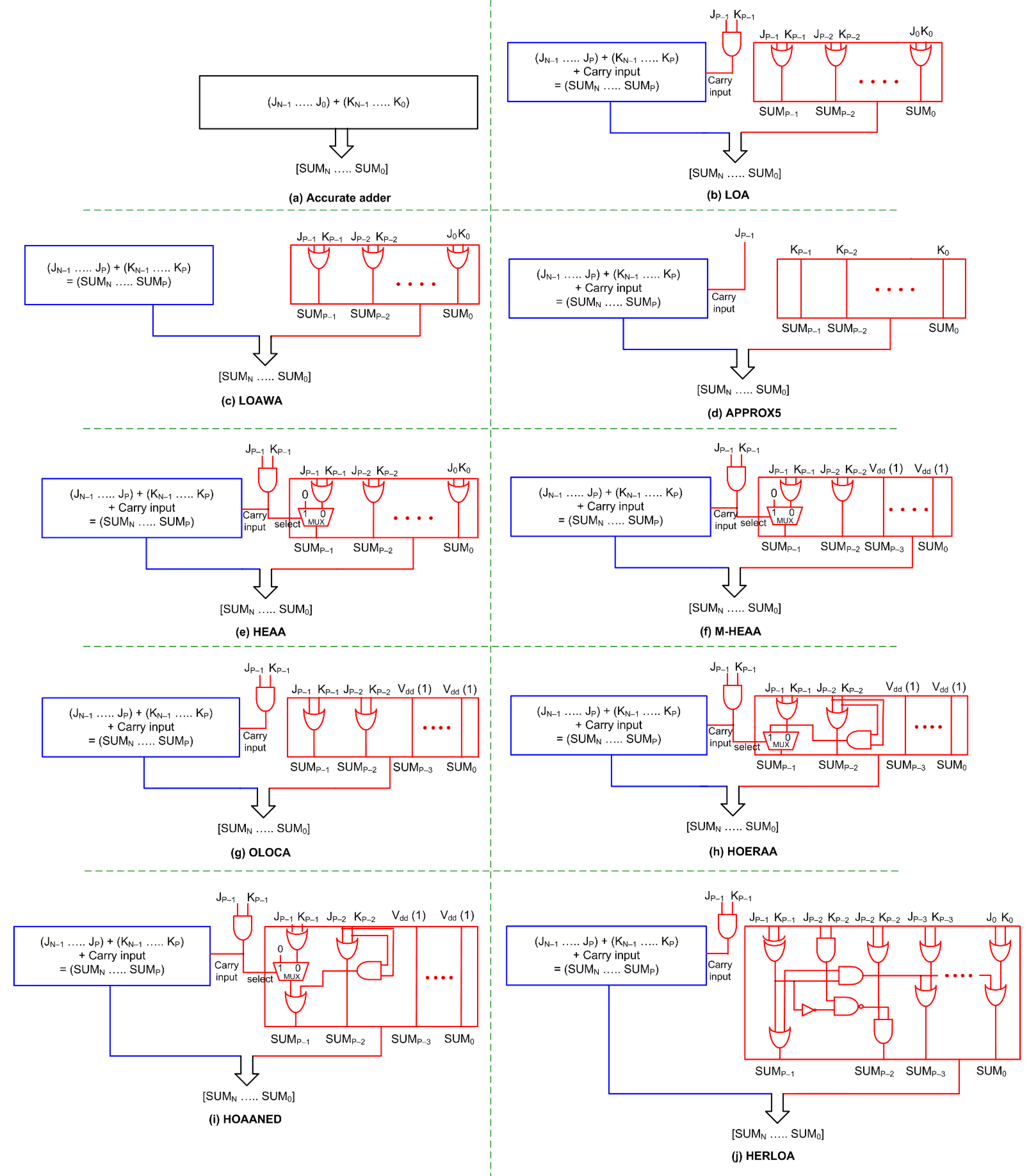
Figure 1 portrays block-level schematics of the accurate adder and various approximate adders which are considered for implementing image compression.
to
represent the most significant bit to the least significant bit of an N-bit adder input, and
. to
represent the most significant bit to the least significant bit of the other adder input.
Figure 1a depicts the accurate adder which can be implemented using a high-speed adder architecture. The exact part of the approximate adders can also be implemented using a high-speed adder similar to the accurate adder.
Figure 1b–j portrays N-bit approximate adders containing (N–P)-bit exact parts and P-bit inexact parts. In
Figure 1b–j, the exact part is depicted in blue and comprises input bits ranging from
to
and
to
. The inexact part is depicted in red, which comprises input bits ranging from
to
and
to
. The exact part of an approximate adder may or may not receive a carry input from the inexact part depending upon its architecture.
In this paper, the accurate adder shown in
Figure 1a and the exact part of the approximate adders shown in
Figure 1b–j are realized using a high-speed carry look-ahead adder (CLA) [
22] for an ASIC-type implementation, and using ahigh-speed native accurate FPGA adder for an FPGA-based implementation. Since the exact parts of the approximate adders are identical, the following discussion is only concerned with the inexact parts of the approximate adders shown in
Figure 1.
Reference [
23] presented a lower part OR approximate adder called LOA, shown in
Figure 1b, where sum bits
to
are calculated by performing a bitwise-OR between the corresponding input bits. LOA performs bitwise AND between
and
of the inexact part to generate and provide a carry input to the exact part.
Figure 1c shows another approximate adder [
24], referred to as LOAWA in [
25], which is similar to LOA but is different in that no carry input is provided from the inexact part to the exact part.
Reference [
26] presented an approximate adder called APPROX5 in [
25], which is shown in
Figure 1d, which forwards input bits
. up to
as the respective sum bits
to
of the inexact part and supplies the input bit
as the carry input to the exact part. Input bits
. up to
. are not used and discarded in APPROX5.
The approximate adder shown in
Figure 1e viz. HEAA [
27], as it is called in [
25], performs bitwise-AND between
. and
; if this results in binary 0, no carry input is provided to the exact part and the inexact part of HEAA would be the same as LOA and LOAWA; however, if binary 1 is the result, HEAA differs in that the sum bit
. is set to 0, while the logic of the remaining sum bits from
to
would be the same as LOA and LOAWA.
Figure 1f depicts M-HEAA [
28] that is derived from an architectural modification of HEAA in which the (P–2) least significant sum bits of the inexact part are set to 1 while the rest of the logic of M-HEAA is the same as HEAA.
Approximate adder OLOCA [
29], shown in
Figure 1g, is obtained based on a modification of LOA in that the (P–2) least significant sum bits of the inexact part are set to 1 while the rest of the logic of OLOCA is the same as LOA.
Approximate adder HOERAA [
25] is shown in
Figure 1h, which features a carry input provided from the inexact part to the exact part that is the same as LOA, HEAA, M-HEAA, and OLOCA. As with M-HEAA and OLOCA, the (P–2) least significant sum bits of the inexact part are set to one in HOERAA. Sum bit
is calculated by performing bitwise-OR between
and
. Sum bit
is produced as the output of a 2:1 multiplexer (MUX), whose select input is the carry input given to the exact part. If the select input is 0, the logical-OR of
and
is produced as
, and if the select input is 1, the logical-AND of
and
is produced as
.
Approximate adder HOAANED [
30] is shown in
Figure 1i that also features a carry input supplied from the inexact part to the exact part similar to LOA, HEAA, M-HEAA, OLOCA, and HOERAA. The logic of
up to
of HOAANED is the same as M-HEAA, OLOCA, and HOERAA. As with HEAA, M-HEAA, and HOERAA, HOAANED also has a MUX in the logic corresponding to
, whose select input is the carry input given to the exact part. If the MUX select input is 0,
and
are OR-ed and
and
are AND-ed, and these two are finally OR-ed to produce
. On the contrary, if the MUX select input is 1, the logical AND of
and
is produced as
.
Another approximate adder called HERLOA, presented in Reference [
31], is shown in
Figure 1j, which features a unique logic circuit used to produce the sum bits of the inexact part. However, the carry input supplied from the inexact part to the exact part has the same logic as LOA, HEAA, M-HEAA, OLOCA, HOERAA, and HOAANED.
In the next section, the performance of the accurate adder is compared with the performance of the approximate adders for digital image compression.
3. Digital Image Compression
Digital images of size 512 × 512 pixels with a grayscale resolution of 16-bits were considered for image compression using MATLAB.
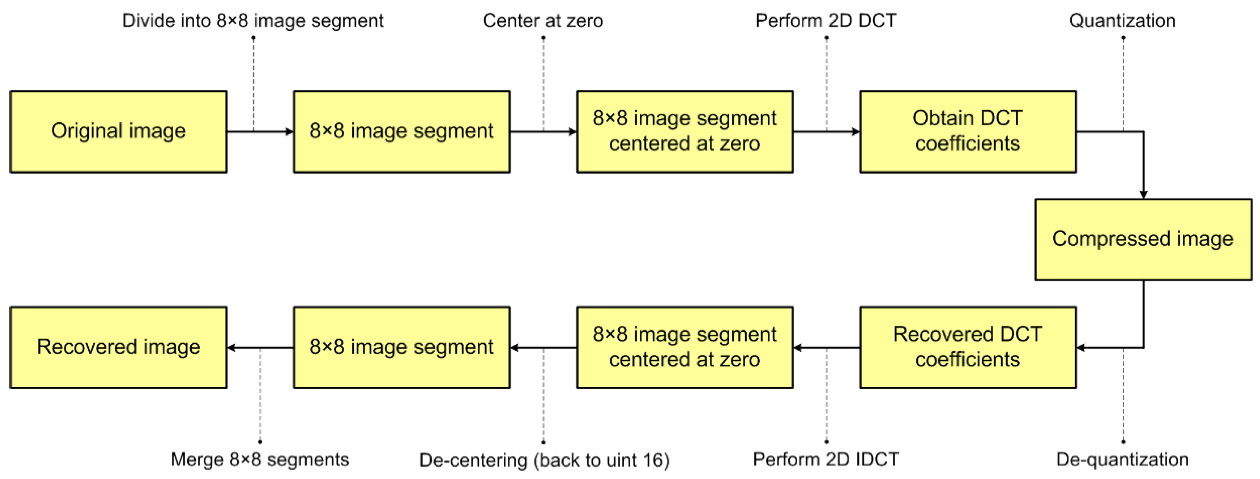
Figure 2 shows a block diagram illustrating the step-by-step procedure involved in JPEG-based image compression and recovery; the mathematical model underlying this procedure is discussed in [
32] and we have used the same for this work.
An original digital image is first divided into a number of 8 × 8 image segment blocks. Next, the grayscale values of these 8 × 8 image segments are centred at zero; in other words, the 16-bit grayscale values are converted from a range of
to
to the range of
to
by subtracting
from all the grayscale pixel values in the 8 × 8 image segment. The zero centering is required to ensure that, after performing a 2D discrete cosine transform (DCT), the lower frequency components would be present on the upper-left corner of the 8 × 8 segment and the higher frequency components would be present on the lower-right corner of the 8 × 8 segment. This is required to ensure that the essential information about an image is not lost during the quantization. The next stage involves the application of a 2D-DCT. During this stage, the multiples of sines and cosines and the sum of the multiples of sines and cosines are stored as constants, since the same values are used for all the 8 × 8 image segments. Accurate multiplication is performed to calculate the product of constant coefficients with the DCT inputs. The calculation of sum/difference of DCT inputs is performed using the accurate adder shown in
Figure 1a and using the approximate adders shown in
Figure 1b–j separately to comparatively analyze the performance of accurate adder and approximate adders based on the resulting quality of compressed images. The next step involves the element-wise division of each 8 × 8 block with the recommended 8 × 8 JPEG quantization matrix [
33] to obtain the compressed image.
To recover the image from a compressed format, the reverse procedure is applied. De-quantization is followed by 2D inverse DCT (IDCT), which is performed by utilizing the built-in IDCT function in MATLAB for both the dimensions on 8 × 8 image segments, and then de-centering is performed by adding to convert the range of pixel values back to the range of 0 to ). Finally, the 8 × 8 image segments are merged to recover the original image in a visual form.
The sizes of accurate adder and approximate adders used for 2D-DCT calculation in image compression are 21-bits. While using 20-bit adders for image compression, a loss of information is observed due to a bit overflow that occurs during the addition. Therefore, 21-bits is found to be an optimum adder length for 16-bit digital image compression.
We considered the La Silla image [
34] and the Black Hole image [
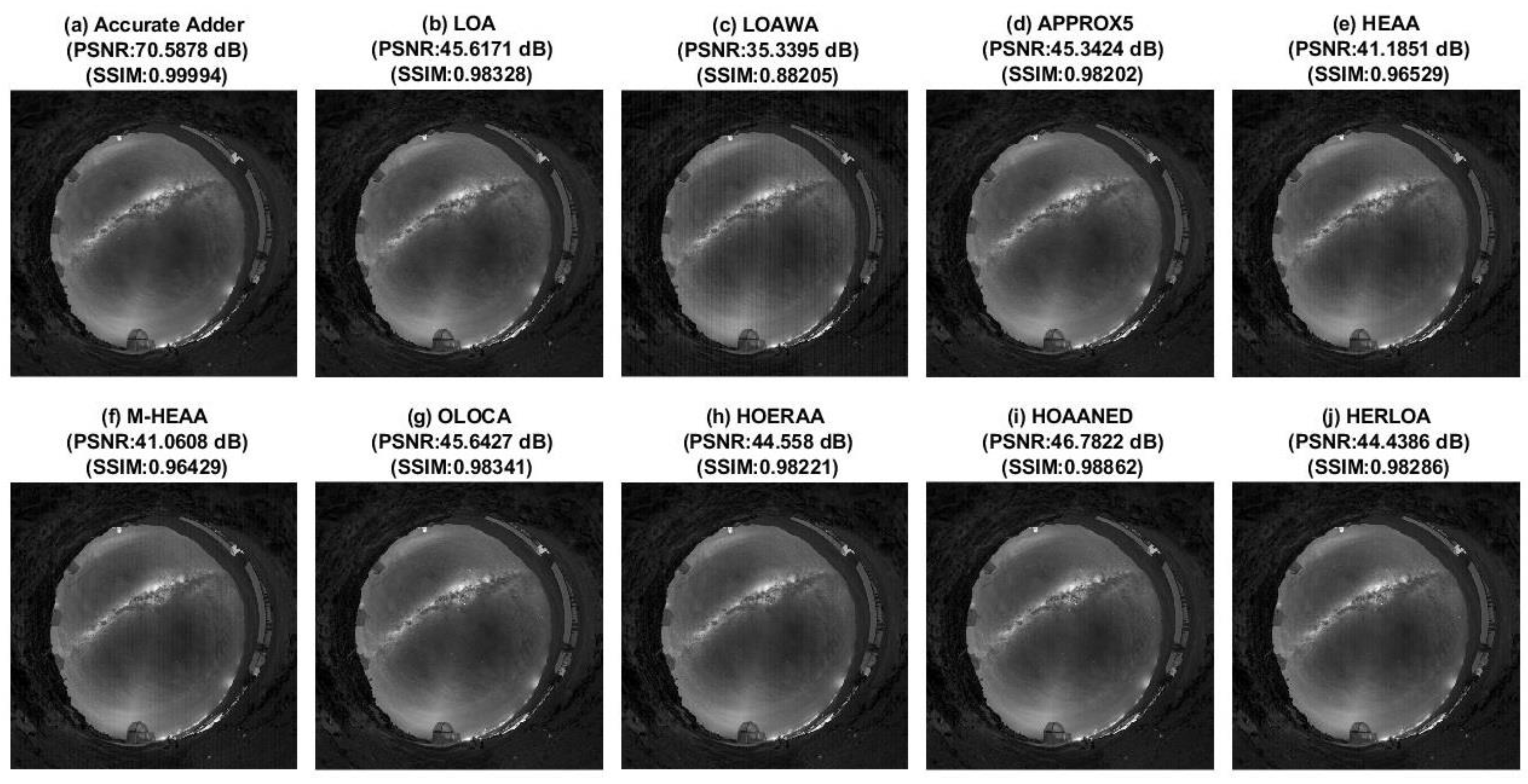
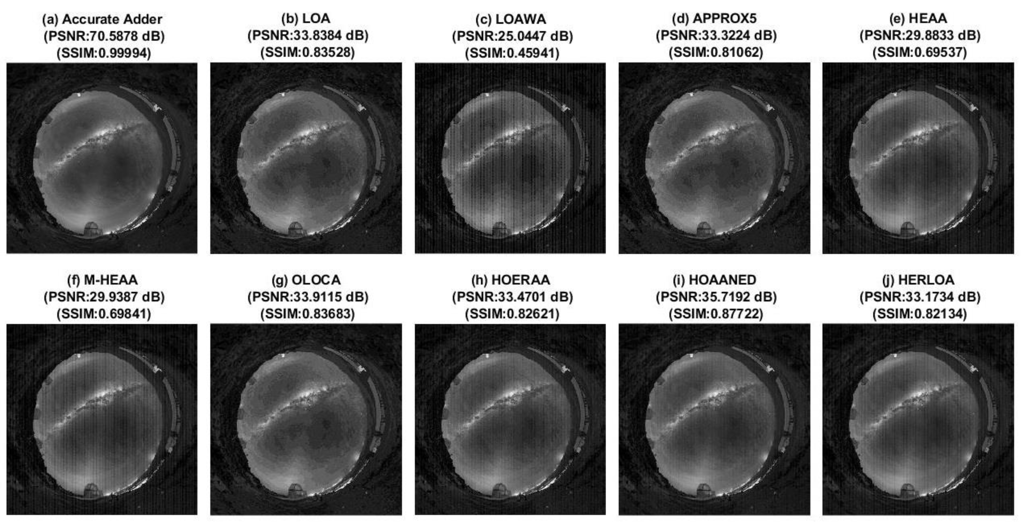
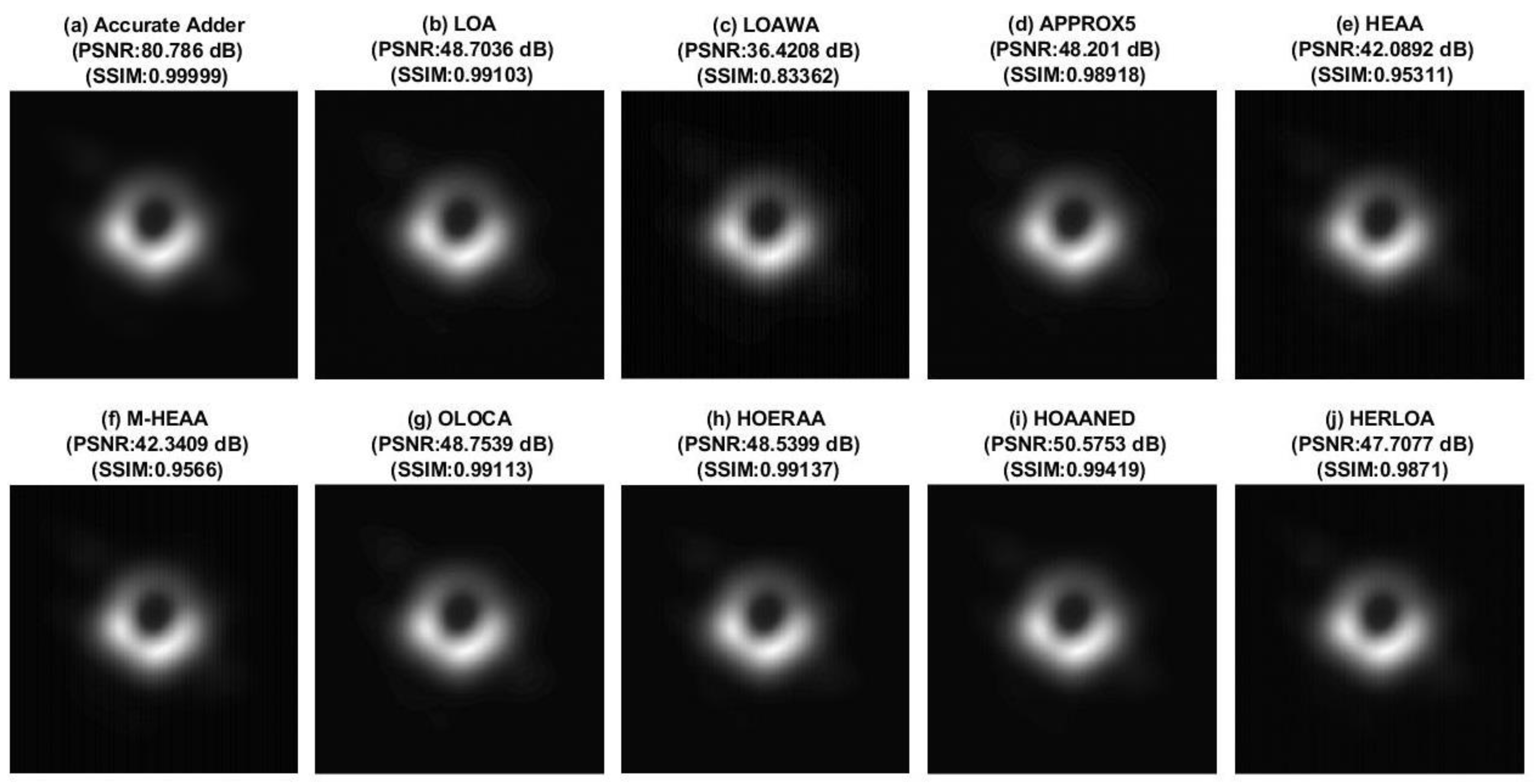
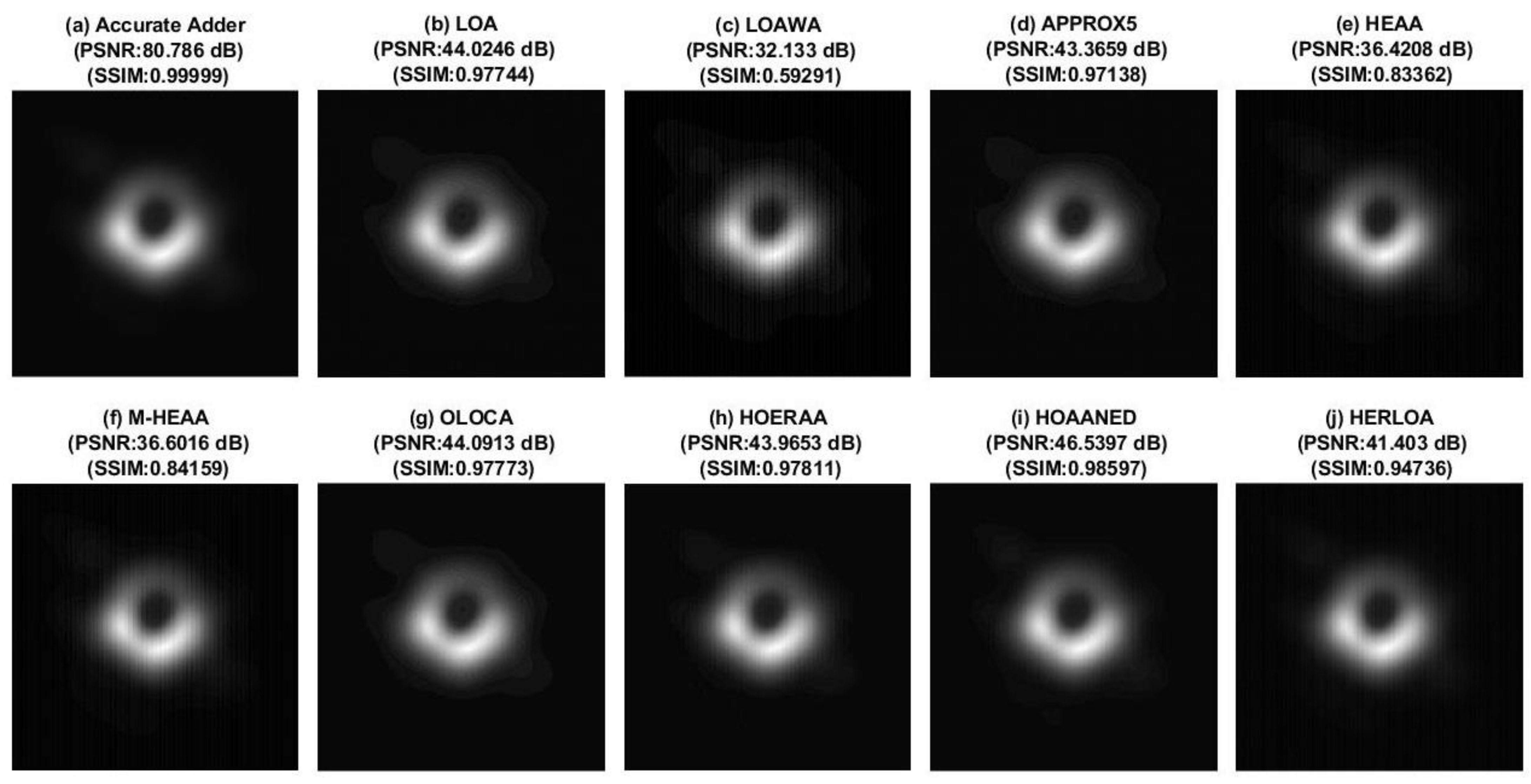
35] for image compression, which are 16 × 3-bit RGB images imported from the European Southern Observatory database. Pre-processing is performed to convert the images into 16-bit 512 × 512 grayscale images before performing compression. The results of image compression and recovery using 21-bit accurate adder and approximate adders for 2D-DCT calculation for the 16-bit La Silla image are shown in
Figure 3,
Figure 4 and
Figure 5. The compressed images obtained using the approximate adders, shown in
Figure 3,
Figure 4 and
Figure 5, consider the use of 10-bits, 11-bits, and 12-bits, respectively, for the inexact part. In
Figure 3,
Figure 4 and
Figure 5, the type of adder used, and the peak signal to noise ratio (PSNR) and structural similarity index metric (SSIM) of the compressed images, are mentioned along with the respective images for a ready reference.
PSNR [
36] and SSIM [
37] are widely used figures of merit in digital image processing. An image with less distortion, which is indicative of less noise, is preferable, as it would enable a high signal to noise ratio. For image processing, PSNR > 30 dB is generally considered to be preferable [
36]. SSIM quantifies the structural similarity of an image of interest in comparison with a reference (original) image. SSIM could vary from decimal 0 to 1, with 0 indicating a complete mismatch and 1 indicating a complete match between the image of interest and the original image. Both PSNR and SSIM are preferred to be high for digital image processing.
The accurate adder recovers the original La Silla image and Black Hole image, with SSIM practically equal to 1, and this is due to the accurate computation. With respect to the La Silla image,
Figure 3 shows many images of reasonably good quality, except for
Figure 3c, which has a slight distortion.
Figure 4 showcases many images of acceptable quality with less distortion, except for
Figure 4c,e,f. Although
Figure 3 is preferable to
Figure 4 overall, a higher approximation, which would also yield an acceptable output quality, is preferred, as that would lead to a greater reduction in the physical design parameters [
25,
30]. Thus,
Figure 4 is said to represent an optimum approximation which is preferable, and
Figure 3 is said to represent an under-approximation.
In
Figure 5, except
Figure 5a, which was obtained through accurate computation, the rest of the images from
Figure 5b–j, which were obtained by approximate computation, are visibly more distorted compared to
Figure 5a, and they are not of an acceptable quality. This is due to over-approximation, which is reflected in
Figure 5.
In general, over-approximation cannot meet the desired output quality, therefore it is not preferred. Under-approximation would improve the accuracy/output quality (here, image quality), but would reduce the savings achievable in the design parameters, therefore it may not be preferable. Hence, an optimum approximation that would guarantee an acceptable accuracy while enabling optimum savings in the design parameters is preferable.
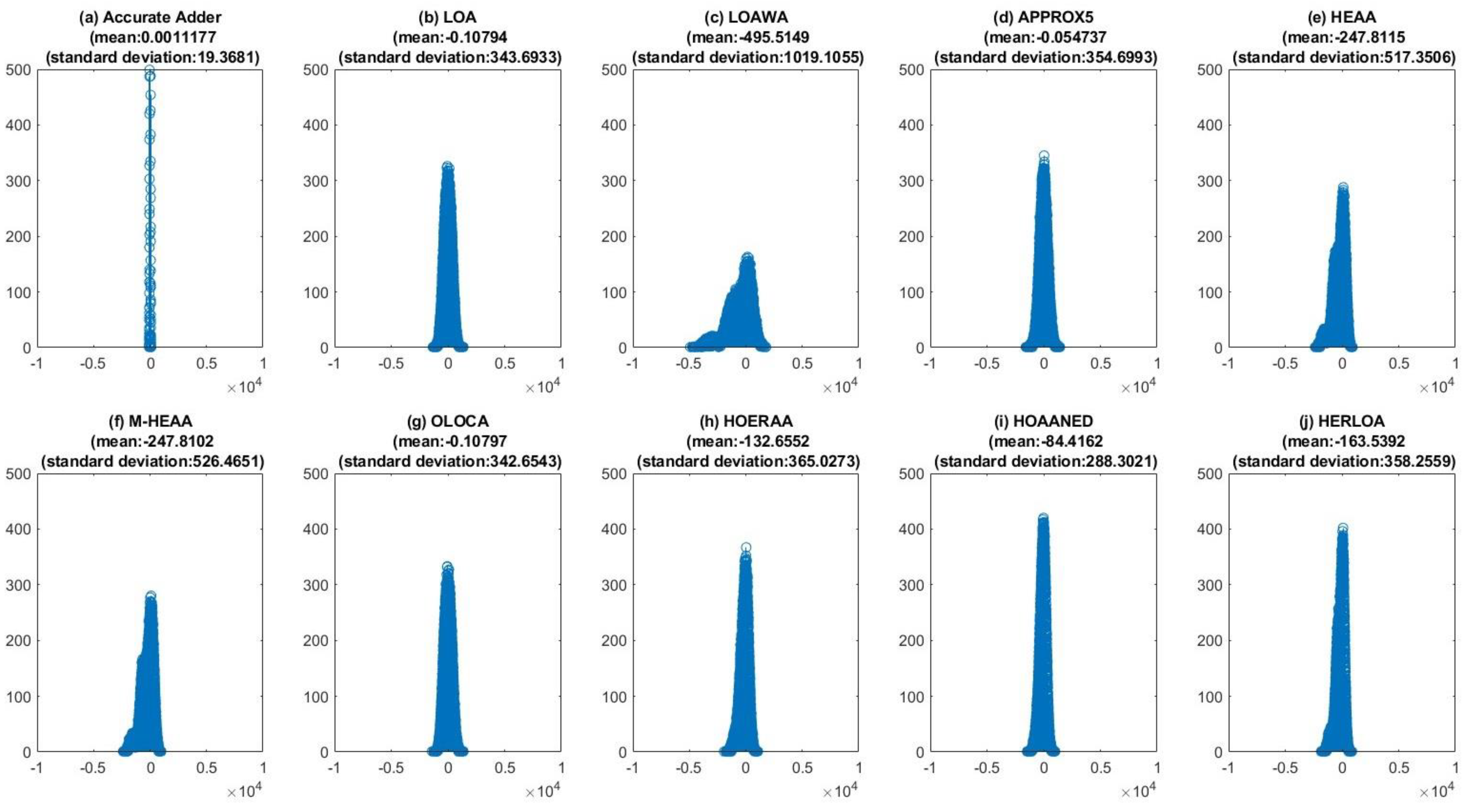
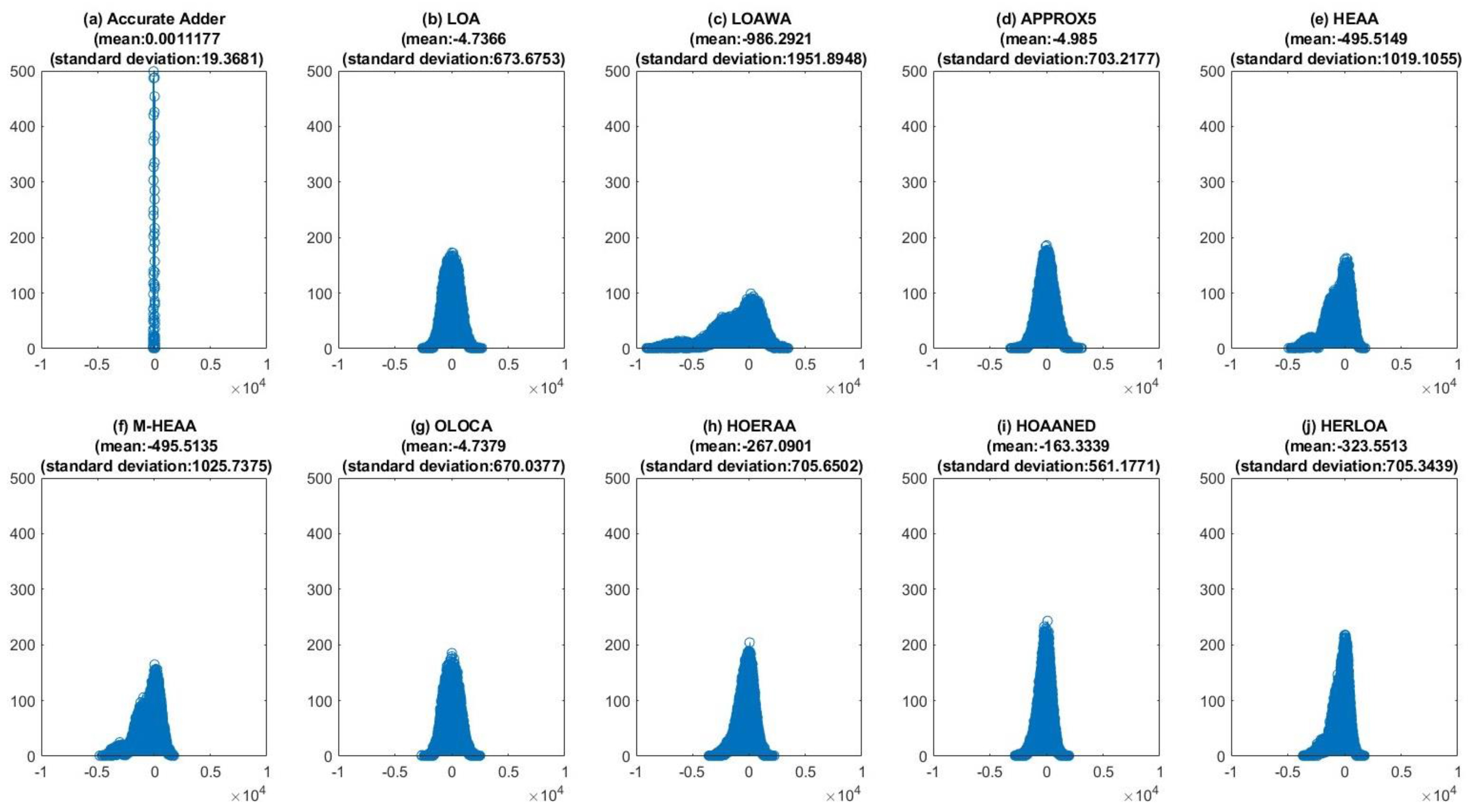
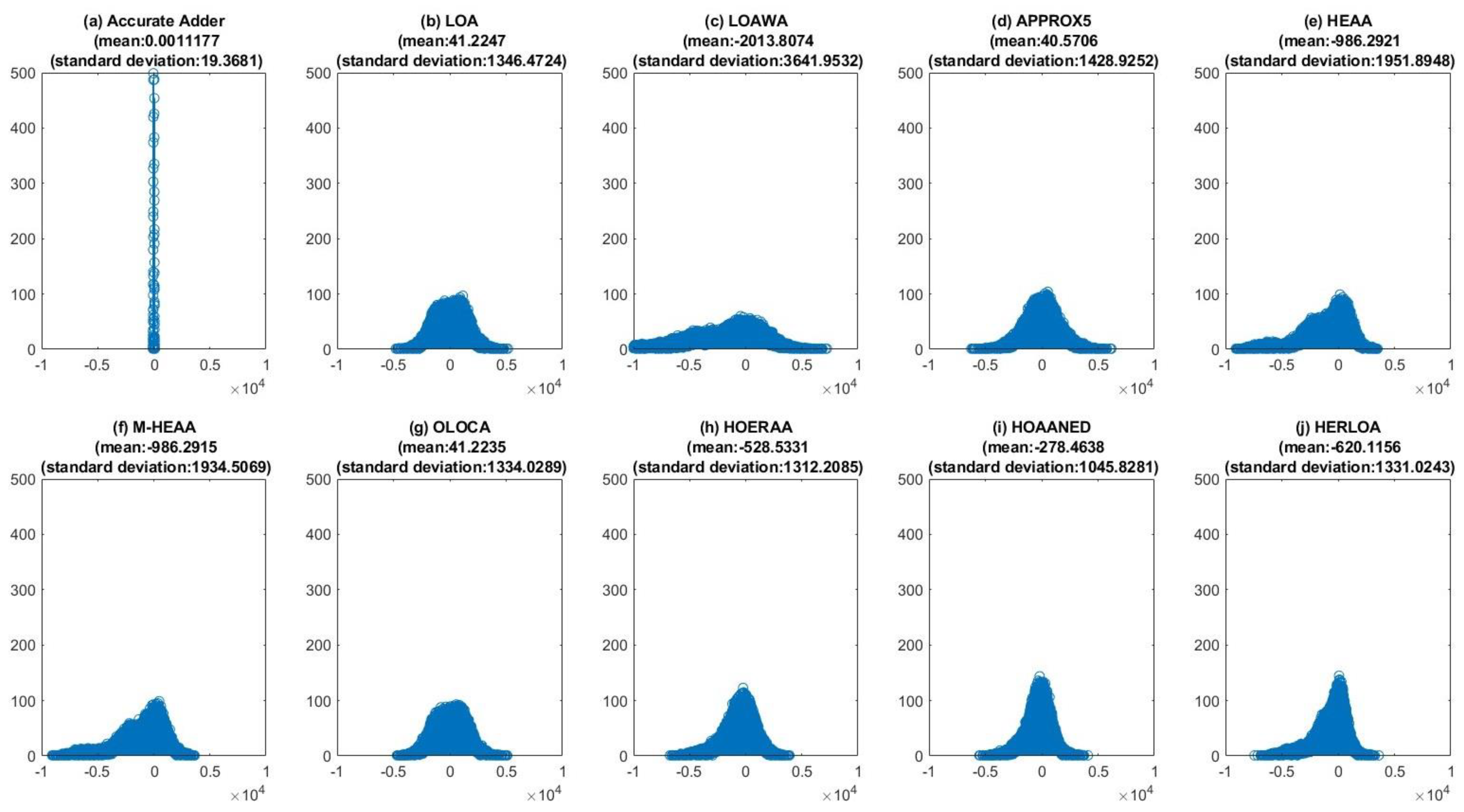
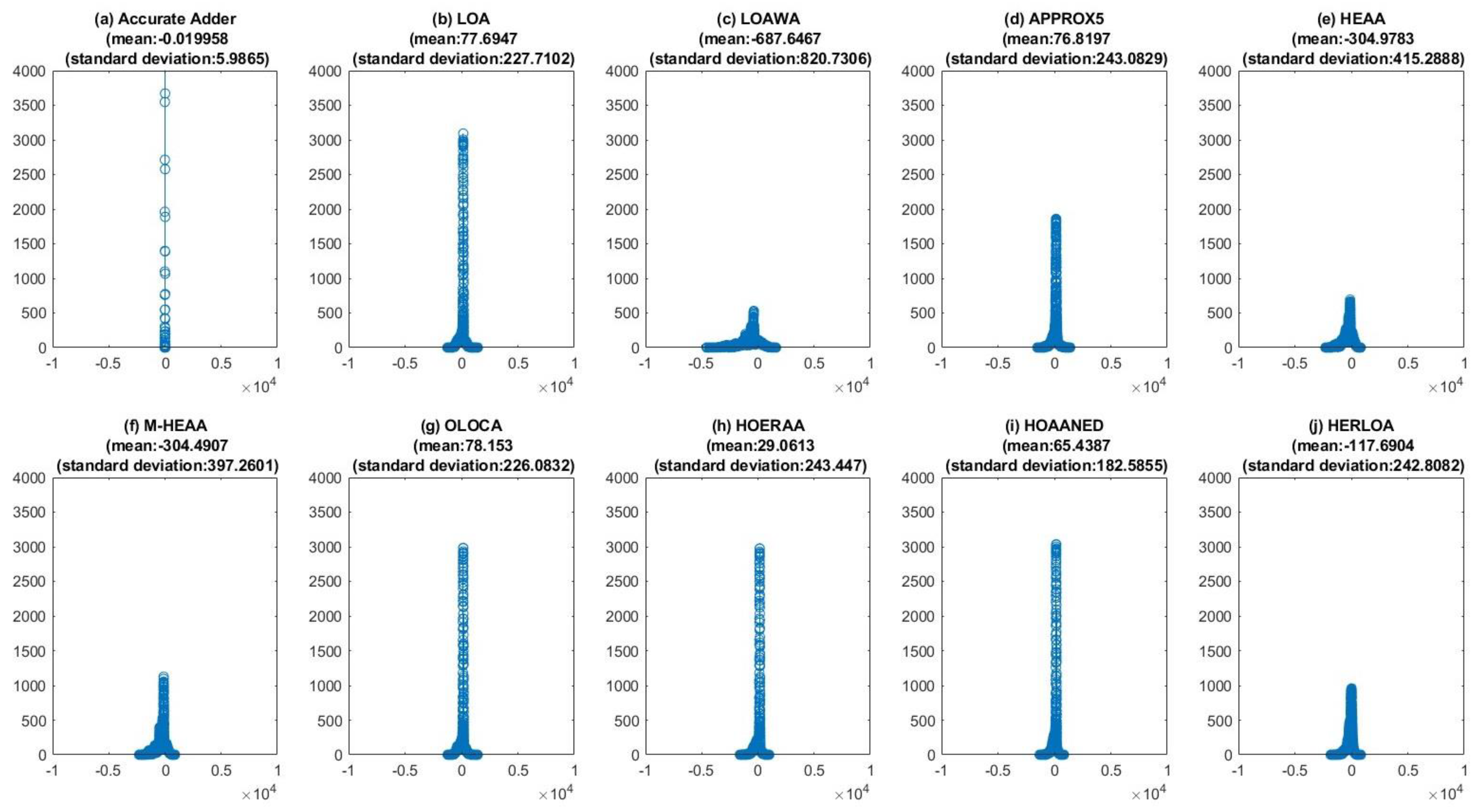
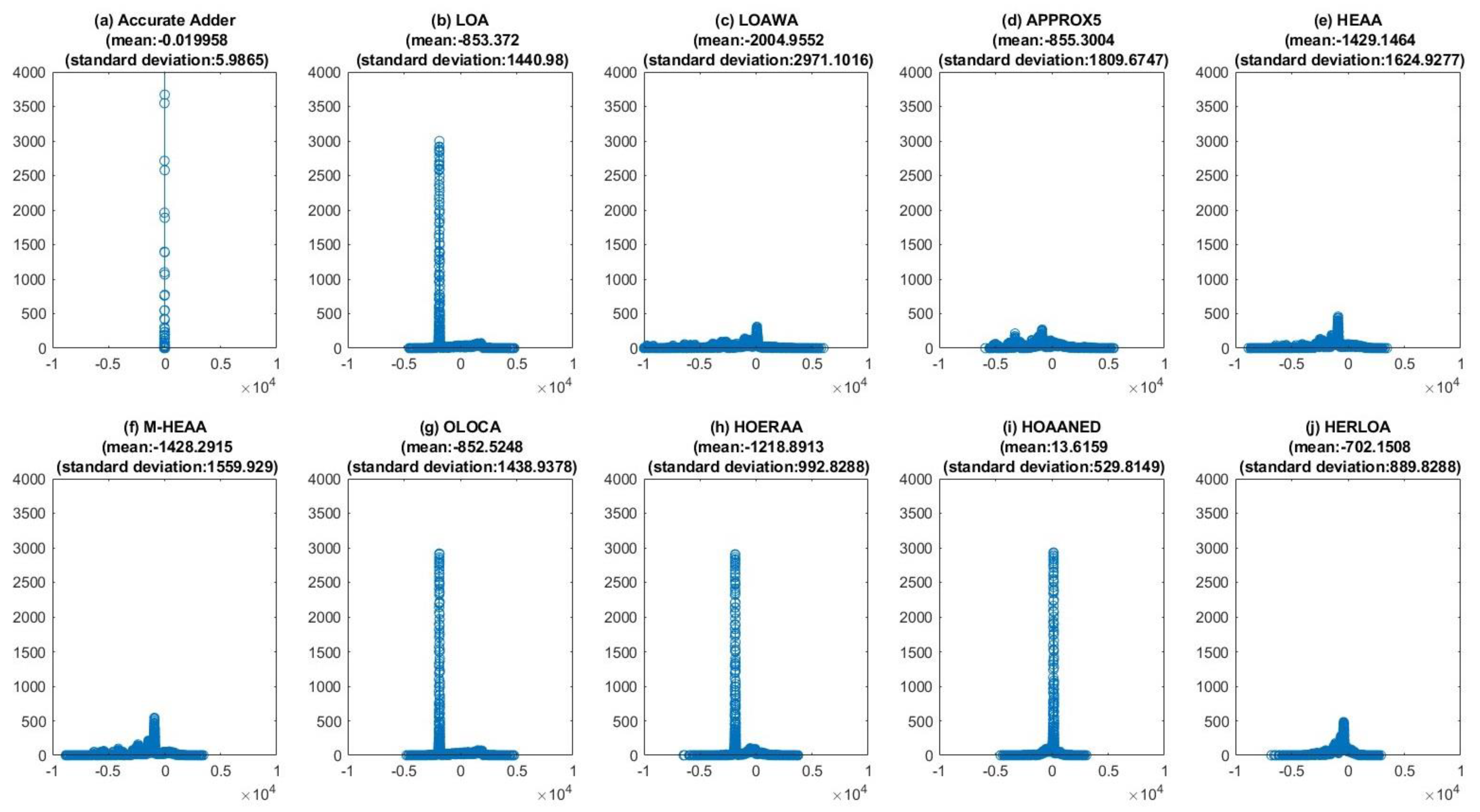
Figure 6,
Figure 7 and
Figure 8 portray the difference in pixel values (DPV) [
36] between the La Silla image compressed using accurate and approximate adders and the original La Silla image.
Figure 6,
Figure 7 and
Figure 8 correspond to approximate adders having 10-, 11-, and 12-bit inexact parts, respectively. In all the DPV plots, the difference between the respective pixel values of the original image and the compressed image is plotted on the
x-axis, and the number of pixels associated with the corresponding DPV is plotted on the
y-axis.
Figure 6a,
Figure 7a and
Figure 8a are the same, which correspond to the image compressed using the accurate adder. In fact, the number of pixels having a zero DPV in
Figure 6a,
Figure 7a and
Figure 8a compared to the original image is close to 6000. This is very high compared to the number of pixels with a zero DPV for the images compressed using different approximate adders. Hence, to precisely capture the DPV for images compressed using approximate adders, and to maintain a uniformity in the Y-axis scale, the Y-axis of the DPV plot corresponding to the accurate adder was curtailed. Nevertheless, this is not an issue, since the DPV plots of approximate adders are of interest and the DPV plot of the accurate adder is only shown for a visual comparison.
Some important observations can be drawn from
Figure 6,
Figure 7 and
Figure 8. Ideally, the image compressed using the accurate adder, shown in
Figure 6a,
Figure 7a and
Figure 8a, should have zero mean and zero standard deviation; however, a very small mean (0.0011177) which is almost zero and a small standard deviation of 19.3681 result for the image compressed using the accurate adder compared to the original image. This is because JPEG image compression is basically a lossy compression technique, and so a negligible DPV manifests, which is the reason for a non-zero mean and a non-zero standard deviation of
Figure 6a,
Figure 7a and
Figure 8a. While moving from
Figure 6,
Figure 7 and
Figure 8, a flattening trend in the DPV plots of the approximate adders can be observed. This essentially implies that the number of pixels having a non-zero DPV increases with an increase in the approximation, which is rather obvious and is to be expected.
Figure 6,
Figure 7 and
Figure 8 uniformly show that the number of pixels having a zero DPV is greater for the images compressed using HOAANED (i.e.,
Figure 6i,
Figure 7i and
Figure 8i) compared to the images compressed using other approximate adders. Though the DPV plots corresponding to the images compressed using HERLOA (
Figure 6j,
Figure 7j and
Figure 8j) have nearly the same number of pixels with a zero DPV as HOAANED, HOAANED consistently reports lower mean and standard deviation values compared to HERLOA for the different approximation scenarios. Hence, HOAANED is preferable to the other approximate adders, which is in agreement with the inference derived from
Figure 3,
Figure 4 and
Figure 5.
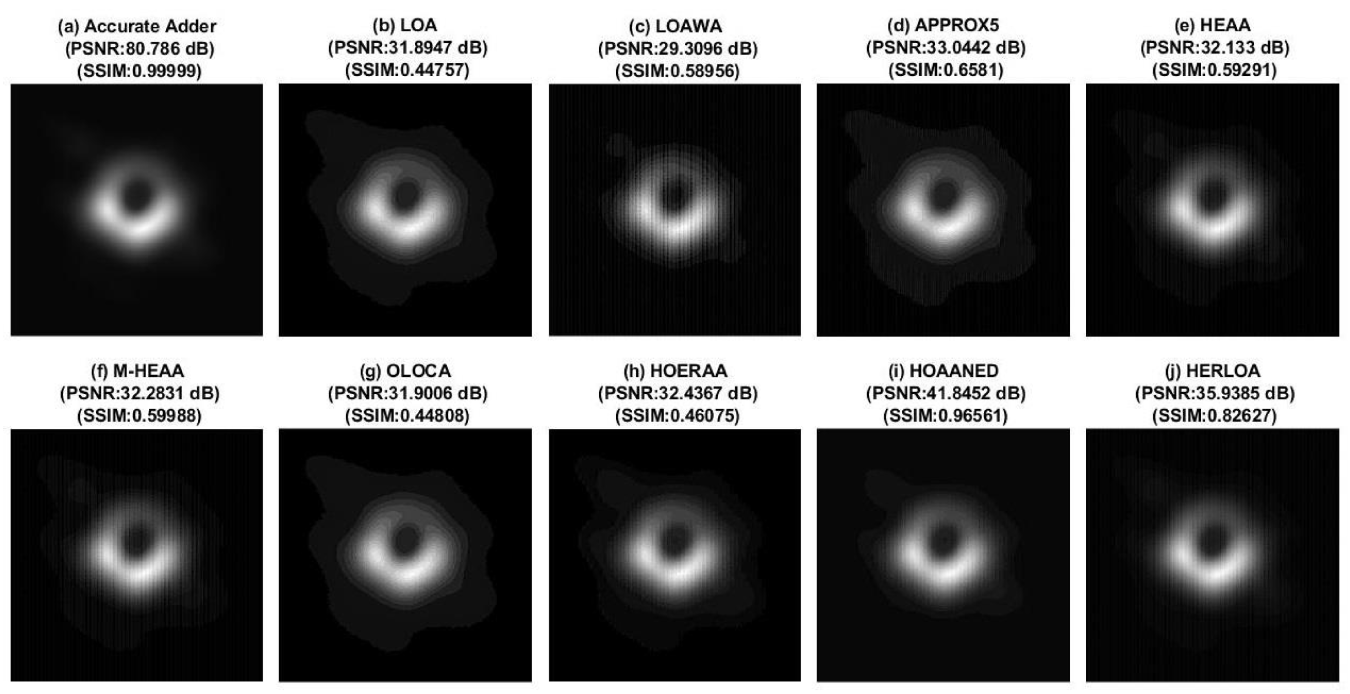
The results of image compression and recovery using 21-bit accurate adder and approximate adders for 2D-DCT calculation for the 16-bit Black Hole image are shown in
Figure 9,
Figure 10 and
Figure 11. The compressed images obtained using the approximate adders shown in
Figure 9,
Figure 10 and
Figure 11 consider the use of 10-bits, 11-bits, and 12-bits, respectively, for the inexact part. In
Figure 9,
Figure 10 and
Figure 11, the type of adder used and the PSNR and SSIM of the compressed images are mentioned along with the respective images for a ready reference.
With respect to the Black Hole image,
Figure 9 shows many images of reasonably good quality, except for
Figure 9c,f, which has noticeable distortions.
Figure 10 shows some images of acceptable quality with less distortion, except for
Figure 10c,e,f. Although
Figure 9 is preferable compared to
Figure 10 overall, as mentioned previously, a higher approximation that would yield an acceptable output quality is preferable, as that would lead to a greater reduction in the design parameters after physical implementation. Hence,
Figure 10 is said to represent an optimum approximation, which is preferable, while
Figure 9 is said to represent an under-approximation. In
Figure 11, except
Figure 11a, which was obtained through accurate computation, the rest of the images from
Figure 11b–j, which were obtained by approximate computation, are visibly more distorted compared to
Figure 11a, and they are not of an acceptable quality. This is due to over-approximation, and
Figure 11 reflects this condition. Given these, a 21-bit adder with an 11-bit inexact part is determined to be an optimum-approximation, i.e., acceptable approximation, and
Figure 4 and
Figure 10 correspond to an optimum approximation. Importantly, from
Figure 4 and
Figure 10, we note that HOAANED, referring to
Figure 4i and
Figure 10i, results in minimum error upon image recovery after compression and it facilitates higher PSNR and SSIM for the compressed images compared to the PSNR and SSIM of the compressed images obtained using other approximate adders. Hence, HOAANED is preferable to its counterparts.
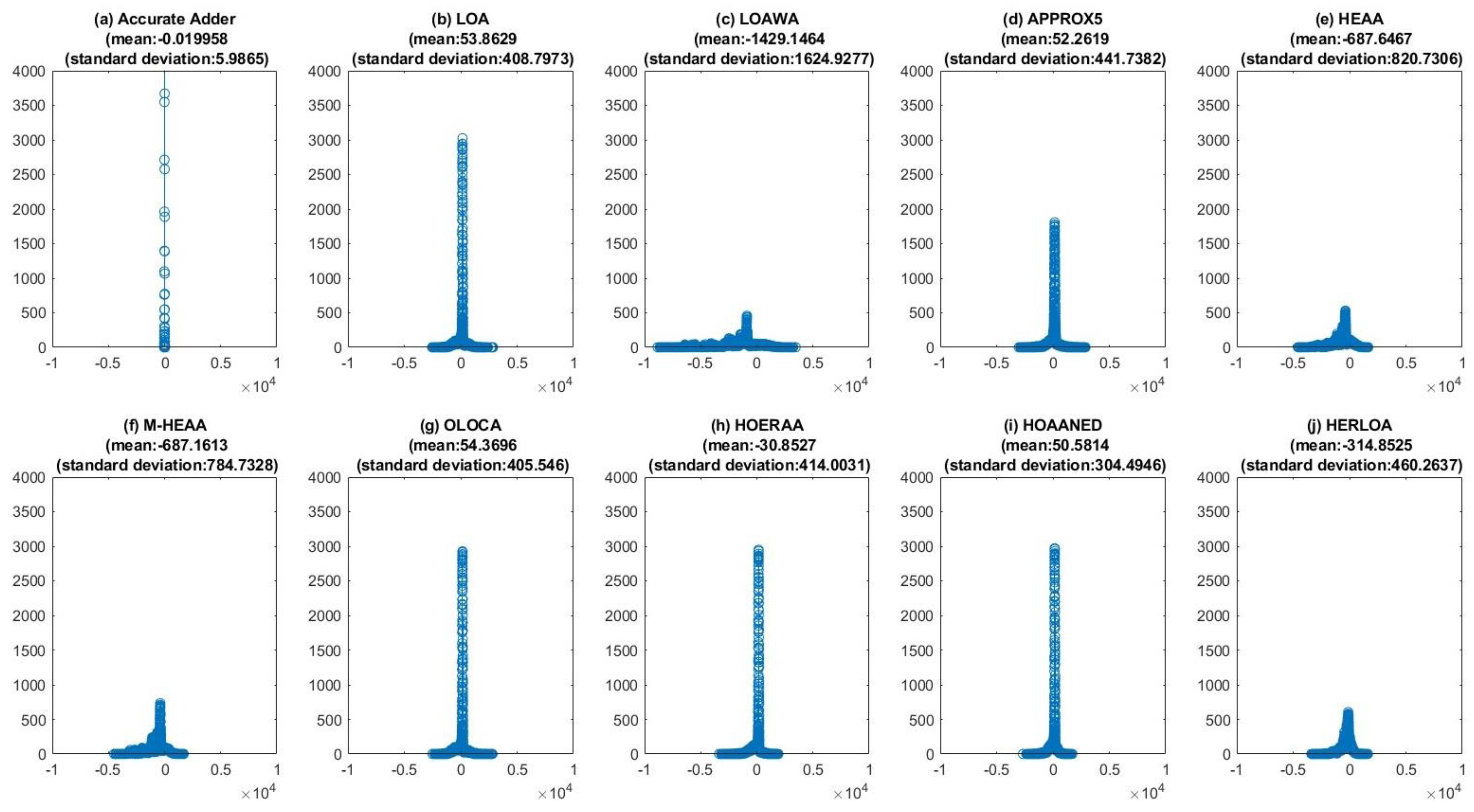
Figure 12,
Figure 13 and
Figure 14 portray the DPV plots of the compressed Black Hole image using accurate and approximate adders in comparison with the original Black Hole image.
Figure 12,
Figure 13 and
Figure 14 correspond to approximate adders having 10-, 11-, and 12-bit inexact parts respectively.
Figure 12a,
Figure 13a and
Figure 14a are the same, which correspond to the image compressed using the accurate adder, and a non-zero mean and a non-zero standard deviation are associated with them due to the lossy JPEG image compression. In fact, the number of pixels that have a zero DPV in
Figure 12a,
Figure 13a and
Figure 14a compared to the original image is found to be close to 20,000. This is much higher compared to the number of pixels that have a zero DPV for the images compressed using different approximate adders. Hence, to precisely capture the DPV for images compressed using various approximate adders, and to maintain a uniformity in the Y-axis scale, the Y-axis of the DPV plot corresponding to the accurate adder has been curtailed. Nevertheless, this is not an issue, since the DPV plots of approximate adders are of interest and the DPV plot of the accurate adder is only shown for a visual comparison. While moving from
Figure 12,
Figure 13 and
Figure 14, a flattening trend in the DPV plots of the approximate adders can be observed, as observed in
Figure 6,
Figure 7 and
Figure 8, which implies that the number of pixels that have a non-zero DPV increases with an increase in the approximation.
Figure 12,
Figure 13 and
Figure 14 also uniformly show that the number of pixels that have a zero DPV is greater for the images compressed using HOAANED (i.e.,
Figure 12i,
Figure 13i and
Figure 14i) compared to the images compressed using other approximate adders. Hence, HOAANED is preferable to the other approximate adders for image compression, which is in agreement with the inference derived from
Figure 9,
Figure 10 and
Figure 11.
The original size of the La Silla image before compression is 491 KB, and the original size of the Black Hole image before compression is 379 KB. The impact of compression on La Silla and Black Hole images using a 21-bit accurate adder and different 21-bit approximate adders with an 11-bit inexact part is presented in
Table 1. While almost all of the approximate adders enable good image compression than the accurate adder, a relatively better image compression is achieved using HOAANED, which is substantiated by the high PSNR and SSIM attained, which is evident from
Figure 3,
Figure 4,
Figure 5,
Figure 9,
Figure 10 and
Figure 11Referring to
Table 1 and
Figure 4a,i and
Figure 10a,i, we note that the La Silla image compressed using HOAANED has a 10.2% smaller file size than the image compressed using the accurate adder, and the Black Hole image compressed using HOAANED has a 70.2% smaller file size than the image compressed using the accurate adder. Typically, when JPEG compression is performed using DCT, very high frequency information which cannot be easily distinguished by a human eye is lost, which results in a lossy compression. This high frequency information loss is more pronounced in the case of the Black Hole image compared to the La Silla image, which is the likely reason for the greater compression achieved for the Black Hole image.
4. Error Metrics and Design Parameters of Approximate Adders
In the previous section, it was noted that the image compression of a 21-bit approximate adder with an 11-bit inexact part represents an acceptable/optimum approximation. Given this, we supplied one million randomly generated input vectors to the accurate adder and approximate adders to calculate their respective sums and subsequently estimate the error. We calculated popular error metrics such as the mean error distance/mean absolute error (MAE) and root mean square error (RMSE) of the approximate adders. MAE and RMSE were calculated using Equations (1) and (2), respectively [
38], given below, where L is the number of random input vectors that is equal to one million. In Equations (1) and (2),
denotes the sum produced by an approximate adder and
denotes the sum produced by the accurate adder.
Table 2 gives MAE and RMSE values corresponding to different 21-bit approximate adders with an 11-bit inexact part. Less MAE and RMSE are observed for HERLOA compared to the other approximate adders. However, HOAANED has a near-normal error distribution [
30], since its positive and negative error magnitudes almost cancel out, which is the reason for its practically zero average error.
The accurate adder and approximate adders were implemented in ASIC- and FPGA-based design environments, and their design parameters were estimated to make a comparison. The ASIC-type implementation utilized the gates of a 32–28 nm CMOS standard cell library [
39]. A typical case high V
t library specification with a supply voltage of 1.05 V and an operating junction temperature of 25 ℃ was considered. Fanout-of-4 drive strength was applied on all the output ports, i.e., the sum bits, and default wire loads were considered. Synthesis, simulation, and estimation of the design parameters were performed using Synopsys EDA tools.
The accurate adder and various approximate adders were first described structurally in Verilog HDL and then synthesized using Design Compiler with speed set as the optimization goal. Functional simulations were performed using VCS by supplying a test bench consisting of about one thousand randomly generated input vectors, which were supplied at a data rate of 1 ns, i.e., 1 GHz. The total (average) power dissipation was estimated by taking into account the switching activity which was captured during functional simulation. PrimeTime, PrimePower, and Design Compiler were used to estimate the critical path delay, total power dissipation, and total area (cells area plus interconnect area) of the adders.
Structurally, a half-adder and five 4-bit CLAs were used to describe a 21-bit accurate adder, while a 2-bit CLA without/with the carry input and two 4-bit CLAs were used to describe the 10-bit exact parts of approximate adders. The CLA design presented in [
22] was used to realize the accurate adder and the exact parts of the approximate adders for an ASIC-based implementation. The standard design parameters estimated are given in
Table 3.
Table 3 reports a significant decrease in delay, area, and power dissipation for the approximate adders compared to the accurate adder. Since the approximate adders have only a 10-bit exact part in contrast to the accurate adder, which is of size 21 bits, their critical path delay would therefore be substantially less. All the approximate adders have the same-sized inexact part, therefore their critical path delay would typically be the same. The logic design of the inexact parts of approximate adders differs, therefore some differences manifest in their area and power dissipation. Nevertheless, since the logic of the inexact parts of approximate adders is reduced compared to the accurate adder, they potentially occupy less area and dissipate less power, as seen in
Table 3. In the previous section, HOAANED was stated to be preferable for image compression, and, from
Table 3, it is found to achieve a 27.1% reduction in delay, 46.4% reduction in area, and 50.3% reduction in power compared to the accurate CLA.
For an FPGA implementation, the accurate adder and approximate adders were described behaviorally in Verilog HDL and synthesized and implemented on an Artix-7 FPGA (Xilinx part: xc7a100tcsg324-3) using Xilinx Vivado design tool (version: 2018.3). The addition operator was used to describe the accurate adder and the exact parts of the approximate adders—this resulted in the utilization of the fast carry logic embedded in an FPGA slice to realize the accurate adder and the exact parts of the approximate adders for high-speed. The ‘Flow_AreaOptimized_high’ strategy was used for synthesis and the default implementation strategy was used. A pair of registers was provisioned before the adder’s inputs and a register was provisioned following the adder’s outputs. The pair of registers before the adder’s inputs help to isolate the adders from the physical inputs-outputs, and this helps to avoid input-output delay and input-output routing delay from impacting the adder’s speed. The estimated FPGA design parameters such as minimum clock period (equivalent to critical path delay), total on-chip power consumption, and the number of LUTs and flip-flops (also called registers) are given in
Table 4.
Similar to
Table 3,
Table 4 also shows a reduction in the design parameters of approximate adders compared to the accurate adder for the same reasons discussed previously. The reduced exact part of the approximate adders compared to the accurate adder leads to a reduction in their minimum clock period. The reduced logic of the inexact part of the approximate adders results in less resource consumption (fewer LUTs and/or registers) and less on-chip power compared to the accurate FPGA adder. As HOAANED was observed to be preferable for image compression in
Section 3, from
Table 4, it is noted that HOAANED achieves an 8% reduction in delay, 19.7% reduction in power, and requires 47.6% less LUTs and 42.2% less registers compared to the accurate native FPGA adder.
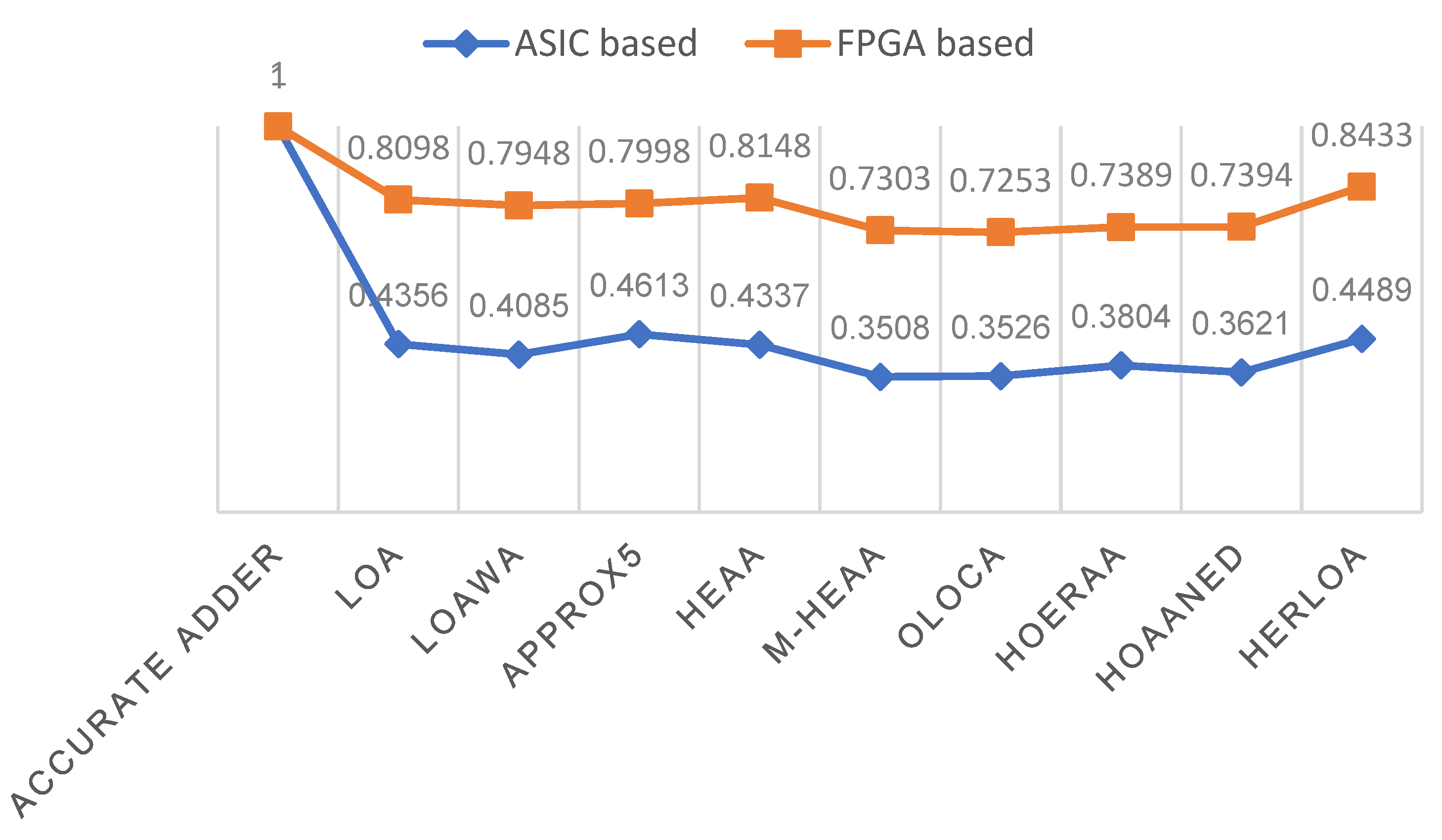
Usually, the product of power and delay (PDP) is computed as a generic figure of merit to quantify the low power/energy efficiency of a digital logic design. The smaller the values of power and delay are, the more desirable; therefore, PDP is also desirable to be less for a digital logic design. Given this, we calculated the PDP for the ASIC- and FPGA-based implementations of accurate adder and approximate adders and normalized them. To normalize the PDP, the highest PDP (which pertains to the accurate adder) is considered as the reference, and this reference was used to divide the PDPs calculated for the accurate adder and the approximate adders. This procedure was followed to normalize the PDPs of ASIC- and FPGA-based implementations separately, and the normalized PDP plots of accurate adder and approximate adders are shown in
Figure 15, which reflect a similar trend. Given that HOAANED is preferable (as noted from
Section 3), it achieves a 26.1% reduction in PDP compared to the accurate adder for an FPGA-based implementation and a 63.8% reduction in PDP compared to the accurate CLA for an ASIC-type implementation.


