Abstract
In wireless applications, such as radars, tens of MHz signals need to be quantized using an analog-to-digital converter (ADC) with a large dynamic range. The detected signal amplitude can be random, with a small or large amplitude. In addition, the dynamic performance is degraded by capacitor mismatches. A 16-bit 120 MS/s pipelined ADC implemented in a 180 nm complementary metal–oxide–semiconductor (CMOS) process is presented in this work. We propose a multi-level dither technique that can significantly enhance the ADC linearity. The injected dither also helps improve the linearity when the ADC handles an input signal with a small amplitude. Traditional dither injection leads to an increase in the amplifier output swing. A counteracting dither injection scheme, both in sub-flash ADC and the multiplying digital-to-analog converter (MDAC), is proposed to remedy this issue. Moreover, capacitor mismatches in the first three pipeline stages are calibrated in a foreground way. The inter-stage residue gain accuracy is guaranteed by a gain-boosting amplifier. To demonstrate the effectiveness of the dither scheme, we obtained the dynamic performance of the ADC with a small input signal (−12 dBFS). The proposed calibration and dither injection technique improved the spurious-free dynamic range (SFDR) from 77 dBc to 85 dBc with −12 dBFS input. With −1 dBFS input, the SFDR remained at over 85 dBc, reaching up to the Nyquist input frequency. Therefore, the dither scheme enhances the dynamic performance when the ADC handles a signal with small amplitude.
1. Introduction
In wireless communication points, such as a base station or radar system, a large spurious-free dynamic range (SFDR) is essential to avoid interference from adjacent channels. In addition, tens of MHz of bandwidth are needed to cover the wideband input signal, thereby demanding a sample rate of >100 MHz [1,2,3,4,5,6]. A pipelined structure is usually employed in these scenarios [7,8,9,10,11,12]. All the pipeline stages operate concurrently, thereby enhancing the overall speed. Moreover, the inter-stage gain improves the accuracy because non-idealities in the back-end stages are attenuated by the gain in the preceding stages. However, two main factors limit the dynamic performance in pipelined analog-to-digital converters (ADCs). A capacitor mismatch in the multiplying digital-to-analog converter (MDAC) causes a bit-weight error. At the point of each comparator threshold, this bit-weight error leads to missing code or non-monotonicity [13]. In addition, the residue gain in the analog domain is requested to match the gain in the digital domain. Otherwise, quantization error leakage happens in the pipeline stage, severely deteriorating the dynamic performance [14]. Analog techniques can remedy the above issues but have a high cost [15,16,17,18]. Recently, the digital method has become preferable to resolve the bit-weight deviation problem, especially as complementary metal–oxide–semiconductor (CMOS) technology is now developing rapidly [19,20,21,22,23,24,25]. In [19,20,21], calibration speed was enhanced using a complicated digital algorithm with a large hardware cost. In [22,23], higher harmonics were calibrated, but the convergence speed was quite low since many parameters need to be calculated. In [24], the ADC was split and the analog circuit complexity significantly increased.
In [1,13], the authors proposed to solve the calibration of capacitor mismatch by switching the MDAC capacitors one by one. Then, all the error codes can be calculated and stored. The ADC output is reconstructed by adding or subtracting these error codes. However, the calibration accuracy is limited by the back-end ADC accuracy and the digital truncation error. Additionally, an input signal with a small amplitude is prone to a differential non-linearity (DNL) error caused by capacitor mismatch. Therefore, if the calibration accuracy is limited, the small signal conversion is degraded. To improve the linearity of the ADC, the dither technique is usually employed [26,27,28]. It provides several virtual comparison thresholds, which enhance the linearity, especially when the input signal amplitude is small. However, the injected dither decreases the signal range, thereby degrading the dynamic performance. Additionally, dither injection causes an increment in the residue signal, which degenerates the amplifier linearity. Moreover, the detailed circuit of the dither injection was not given.
This work proposes a multi-level dither technique that is implemented in a 16-bit 120 MS/s pipelined ADC. The proposed dither injection scheme is employed in both the flash sub-ADC and the MDAC parts. The voltage swing increment of the flash dither and MDAC dither are counteracted by each other. The dither signal in the residue signal path is subtracted in the digital domain, thus avoiding any dither leakage issue. The architecture of the whole ADC and the proposed dither scheme are introduced in Section 2. Section 3 gives the circuit implementation of the dither injection method in a 16-bit 120 MS/s pipelined ADC. The measurement results are given in Section 4. Finally, a conclusion is provided in Section 5.
2. Architecture of the Proposed Dither Injection Scheme
The linearity improvement effect relies on the number of the dither level [28,29]. We employ the theory in the 16-bit pipelined ADC, in which each stage consists of a flash sub-ADC and an MDAC. As shown in Figure 1, the first two stages resolve more bits than the latter stages owing to a trade-off between the power efficiency and circuit complexity [27]. Capacitor mismatches in the first three stages are calibrated, whereas the capacitor matching accuracy is enough in the back-end stages. The residue gain accuracy is guaranteed by the gain-boosting technique, thus avoiding a complicated background calibration algorithm [17]. For instance, the amplifier output in the first pipelined stage needs a 12-bit accuracy for the back-end stage. Therefore, the loop gain and bandwidth should achieve over 72 dB and 310 MHz, respectively. The proposed dither technique is adopted in the first pipeline stage, and the dithering effect is propagated to all the later pipeline stages.
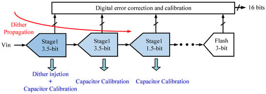
Figure 1.
Block diagram of the proposed analog-to-digital converter (ADC).
Figure 2 illustrates a diagram of the first pipeline stage. The input signal (Vin) is sampled simultaneously by the sub-ADC with flash structure and the DAC capacitor (Cs). The sub-ADC employs 16 comparators, and their outputs (D) are used to switch the 16 capacitors in the MDAC directly, thereby saving time and improving the speed.
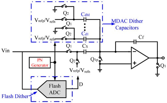
Figure 2.
Schematic of the first pipeline stage with flash dither and multiplying digital-to-analog converter (MDAC) dither.
With this structure, the amplifier output can be approximately expressed as
where Ci is the ith sampling capacitor, and Vref is the reference voltage. Vref equals the difference between the top reference (Vrefp) and the bottom reference (Vrefn). Cf is the feedback capacitor. It can be seen that the amplifier output is confined to the range from −1/2Vref to 1/2Vref. With the traditional dither injection scheme, the amplifier output exceeds this range [11]. Herein, we propose to inject the dither signal in both the sub-ADC and the DAC capacitor, which are called flash dither and MDAC dither in this work, respectively. The flash dither is realized by shifting the thresholds, which is explained in the next section. The DAC dither is implemented with an added capacitor array, which is switched by a multi-bit pseudo number (PN) generator. Note that the dither effect can be propagated along the pipeline chain, so it can also benefit the back-end pipeline stages.
3. Dither Injection Scheme and Its Circuit Implementation
Residue transfer curves are employed to explain the proposed counteracting dither technique. In Figure 3a, the black wave represents an ideal residue–input relationship curve, and the colored dots show the uniformly distributed dither injection locations. Figure 3a only shows six levels for simplicity. In Figure 3b, one level of dither around the threshold Vth1 is exemplified to depict the proposed counteracting dither technique.
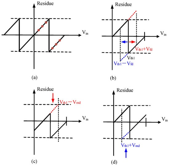
Figure 3.
Residue transfer curves (a) with dither injection locations (b) with a positive or negative flash dither (c) with a positive flash dither and a negative MDAC dither (d) with a negative flash dither and a positive MDAC dither.
The red arrow means a positive dither injection, and the blue one means a negative dither injection, both in the sub-ADC. Note that the dither injection causes the residue to exceed the original swing. The voltage swing due to the flash dither now ranges from −Vref/2 − Vfd to Vref/2 + Vfd, where Vfd is the flash dither amplitude. This voltage swing increment occupies the redundancy range that is otherwise allocated for other non-ideal factors, such as noise and offset. In addition, the inter-stage amplifier induces non-linearity owing to this larger voltage swing. To remedy this issue, we propose a counteracting dither technique. In Figure 3c,d, we inject a dither signal in the MDAC, and the direction is opposite to the flash dither. As shown in Figure 3c, the flash dither is positive (+Vfd) while a negative one (−Vmd) is injected, and thus the residue swing restores to the original range. The other case is shown in Figure 3d. Consequently, if Vfd equals Vmd, the maximum amplifier output remains the same if no dither signal is injected. The flash dither can linearize the injected pipeline stage, while the MDAC dither can be propagated to the back-end stages. The above dither injection scheme for Vth1 is simultaneously executed in all the 16 comparators in the flash ADC. The residue signal is randomized, so spurs from some uncalibrated factors are broken into the noise floor. The flash dither does not influence the final conversion result because it is corrected by the redundancy. Nevertheless, the MDAC dither must be precisely subtracted in the digital domain to avoid any dither leakage.
The number of the dither level determines the effect of the linearity improvement. We employ a 10-bit level MDAC dither. These dither levels are uniformly distributed in each sub-range. To realize the abovementioned counteracting dither technique, we modify the original MDAC and sub-ADC. The MDAC dither is realized by a capacitor array controlled by a dither generator and logic circuit, as shown in Figure 4. The least significant bit (LSB) of the MDAC dither is Vsub/2M, where Vsub is the sub-range voltage, and M is the MDAC dither bit used. Note that the LSB of the MDAC dither amplitude is quite small. As a result, the dither DAC consists of a capacitor array with bridge capacitors, which can attenuate the weight of the capacitors and realize the small dither amplitude. In Figure 4, Cb2 attenuates the weights of C0 and C1, while Cb1 can attenuate the weights of C0 to C5 furthermore. The dither DAC is switched by a controller, as shown in Figure 5. The multi-level dither signal is generated by linear feedback shift registers (LFSR) designed in the digital domain [30].
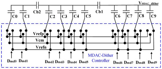
Figure 4.
Circuit of the MDAC dither.

Figure 5.
Circuit of the MDAC dither controller.
Only a 1-bit MDAC dither controller is exemplified for simplicity. Q1 and Q2 are the sampling phase and the amplifying phase, respectively. During the sampling phase, Q1 is high, and the bottom plate of the corresponding dither capacitor is switched to a common mode voltage (Vcm). Then, during the amplifying phase, Q1 becomes low, and Q2 is high. The controlling signal Top or Bot becomes valid, according to the dither generator outputs (Dmdp and Dmdn). Therefore, the controller output switches the bottom plate of the dither capacitor to Vrefp or Vrefn, realizing the MDAC dither function. The controller output configuration during the amplifying phase is shown in Table 1.

Table 1.
The controller output.
The flash sub-ADC contains 16 comparators, as shown in Figure 6. During the sampling phase (Q1), the input signal (Vs = Vip − Vin) and the reference voltages are sampled to C1 and C2, respectively. For instance, the ith comparator samples the differential reference voltages Vthp[i] and Vthn[i], respectively. The charge on these capacitors during the sampling phase are expressed as:
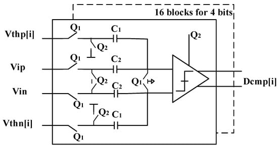
Figure 6.
Circuit of the 4-bit flash ADC with 16 comparators.
After the sampling ends, Q2 becomes high, and the input signals and reference voltages are all grounded. According to the principle of charge conservation, the differential input of the comparator core circuit is:
where Vth is the differential threshold voltage. It is noted that the capacitor mismatches in flash sub-ADC only causes an equivalent comparator offset, which can be absorbed by inter-stage redundancy. The comparator consists of a preamplifier and a latch [31,32]. In traditional flash ADCs, the threshold voltage can be generated by a simple voltage buffer. In this work, these threshold voltages are dithered, as in Figure 7.
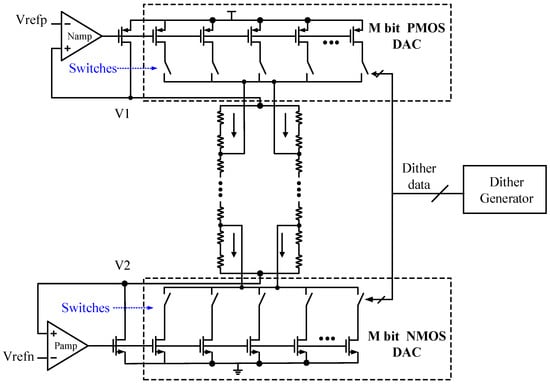
Figure 7.
Circuit schematic of the dithered threshold generator for the 16 comparators.
The proposed flash dither scheme employs a resistor DAC with different bias currents, which are controlled by the dither generator output. As in Figure 7, a traditional voltage buffer is modified to implement the flash dither. Owing to the two negative feedback loops, V1 and V2 are nearly equal to Vrefp and Vrefn, respectively. All the 16 comparator thresholds are obtained from the two resistor chains. In this work, we added one resistor to each end of the resistor chain and two controlled currents to flow through the middle resistors. Ia and Ib are complementary, their sum is I and they are controlled by the N-bit dither codes. Therefore, these two currents flow into or out of the buffer, determined by the dither bit. The dither voltage can be calculated as follows:
Then, all the 16 comparator thresholds increase or decrease simultaneously, thereby realizing multi-level dither injection in the flash ADC. Note that the same dither bits are employed to control the flash dither and the MDAC dither so that the voltage swing increment is counteracted. Although the mismatch between these two dither injections causes a small swing incensement, it can be tolerated by the inter-stage redundancy.
4. Measurement Results
The proposed 16-bit 120 MS/s pipelined ADC with this novel dither scheme was implemented on a 180 nm CMOS process. Figure 8 illustrates the layout photo and the corresponding chip photo. The whole ADC takes up about 3.5 × 1.9 mm2, and the circuit for flash dither and MDAC dither occupies about 1.54 mm2, which is 23% of the whole ADC. The unit capacitor of the first stage is 18.6 × 20 μm2. When the extra area is allocated for the capacitor, the matching accuracy is still worse than 16-bit according to the PDK file. The ADC consumes 347 mW, in which the additional circuit for the dither scheme only occupies about 5 mW. Figure 9 depicts the power spreadsheet of the main building blocks.
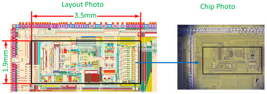
Figure 8.
Layout photo of the proposed ADC and its chip photo.
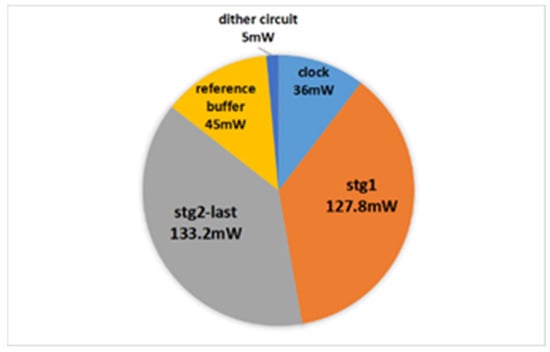
Figure 9.
Power spreadsheet of the main building blocks.
To demonstrate the effectiveness of the dither scheme, we obtained the dynamic performance of the ADC with a small input signal (−12.7 dBFS). As shown in Figure 10, without calibration or dither injection, the SFDR was about 78 dBc. This result is mainly due to a capacitor mismatch. With capacitor mismatch calibration, the SFDR improved to 81 dBc, as depicted in Figure 11. However, the small signal is prone to the residual uncalibrated error, and thus it only achieved a 3 dB improvement. In Figure 12, it can be seen that the SFDR could be significantly enhanced to 85 dB thanks to the proposed flash dither and MDAC dither.
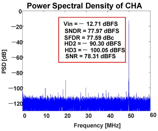
Figure 10.
Dynamic performances before calibration (where SFDR is the spurious-free dynamic range, and SNDR is the signal-to-noise-and-distortion ratio).
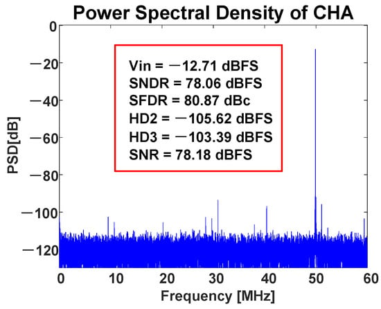
Figure 11.
Dynamic performances after calibration but without dither injection.
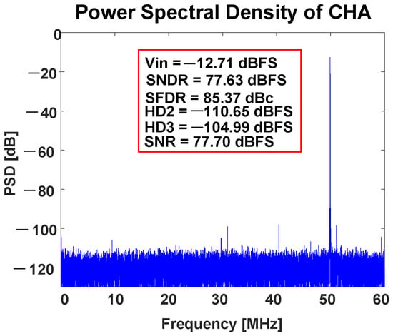
Figure 12.
Dynamic performances with calibration and dither injection.
With a large input signal (about −1 dBFS), the dynamic performance relied mainly on the analog front end. As depicted in Figure 13, after calibration, the SFDR of the ADC with a low frequency input could obtain about 90 dBc. Even with Nyquist input, the SFDR remained at over 85 dBc.
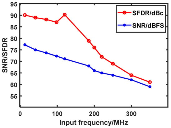
Figure 13.
Dynamic performances with different input frequencies.
The capacitor mismatch also degraded the differential non-linearity (DNL) and integral non-linearity (INL). With the proposed calibration and dither injection scheme, DNL improved from 0.4 LSB/−0.41 LSB to 0.39 LSB/−0.41 LSB, and INL improved from 8.3 LSBs/−6.3 LSBs to 3.2 LSBs/−4.5 LSBs, as depicted in Figure 14 and Figure 15. According to the measurement results, the Walden figure of merit (FoM) was 416 fj/conv-step.
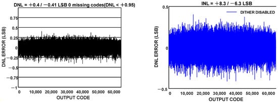
Figure 14.
DNL and INL results without calibration or dither.
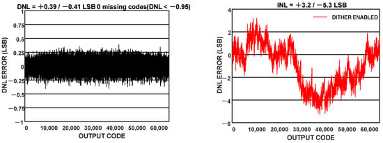
Figure 15.
DNL and INL results with calibration and dither.
Table 2 illustrates the comparison results with prior works that focused on similar ADC types. Note that only [27] and this work cared about the dynamic performance with a small input signal. Compared to [27], the FoM value in our work was more competitive. Moreover, the schemes proposed in [1,13] could barely handle a large input signal, as no dither injection was employed. Comprehensively, the proposed calibration and dither scheme greatly improve the dynamic performance and produce a relatively better FoM value.

Table 2.
Performance of the Proposed ADC and Comparison with Previous Works.
5. Conclusions
A novel dither injection method using both flash and MDAC was proposed and verified in a 16-bit 120 MS/s pipelined ADC. The flash dither can linearize the first stage, while the MDAC dither propagates to the back-end ADC. The voltage swing increment is counteracted by other increments, significantly maintaining the linearity of the residue amplifier. The dither scheme enhances the dynamic performance when the ADC handles a signal with small amplitude. The proposed calibration and dither injection technique improved the SFDR from 77 dBc to 85 dBc with −12 dBFS input. With −1 dBFS input, the SFDR remained at over 85 dBc, reaching up to the Nyquist input frequency. Compared with the previous works, the proposed work achieves a competitive FoM value while quantizing a small input signal with high dynamic performance.
Author Contributions
Conceptualization, J.W.; methodology, J.W. and H.X.; software, J.W.; validation, X.C. and T.L.; formal analysis, J.W.; investigation, H.X.; resources, J.W.; data curation, T.L.; writing—original draft preparation, J.W.; writing—review and editing, J.W.; visualization, H.X.; supervision, H.X.; project administration, H.X.; funding acquisition, J.W. All authors have read and agreed to the published version of the manuscript.
Funding
This work is supported by a SOC project that needs to maintain secrecy.
Data Availability Statement
The data presented in this study are available on request from the corresponding author.
Acknowledgments
Thanks to those engineers who contributed to the layout and testing work.
Conflicts of Interest
The authors declare no conflict of interest. The funders had no role in the design of the study.
References
- Zheng, X.; Wang, Z.; Li, F.; Zhao, F.; Yue, S.; Zhang, C.; Wang, Z. A 14-bit 250 MS/s IF Sampling Pipelined ADC in 180 nm CMOS Process. IEEE Trans. Circuits Syst. I Regul. Pap. 2016, 63, 1381–1392. [Google Scholar] [CrossRef]
- Murmann, B.; Boser, B.E. A 12-bit 75-MS/s Pipelined ADC Using Open-Loop Residue Amplification. IEEE J. Solid-State Circuit 2003, 38, 2040–2050. [Google Scholar] [CrossRef]
- Liu, H.-C.; Lee, Z.-M.; Wu, J.-T. A 15-b 40-MS/s CMOS Pipelined Analog-to-Digital Converter with Digital Background Calibration. IEEE J. Solid-State Circuit 2005, 40, 1047–1056. [Google Scholar] [CrossRef]
- Fang, B.-N.; Wu, J.-T. A 10-Bit 300-MS/s Pipelined ADC with Digital Calibration and Digital Bias Generation. IEEE J. Solid-State Circuit 2013, 48, 670–683. [Google Scholar] [CrossRef]
- Wu, J.; Chen, C.-Y.; Li, T.; He, L.; Liu, W.; Shih, W.-T.; Tsai, S.S.; Chen, B.; Huang, C.-S.; Hung, B.J.-J.; et al. A 240-mW 2.1-GS/s 52-dB SNDR Pipeline ADC Using MDAC Equalization. IEEE J. Solid-State Circuit 2013, 48, 1818–1828. [Google Scholar]
- Brandolini, M.; Shin, Y.J.; Raviprakash, K.; Wang, T.; Wu, R.; Geddada, H.M.; Ko, Y.J.; Ding, Y.; Huang, C.S.; Shih, W.T.; et al. A 5 GS/s 150 mW 10 b SHA-Less Pipelined/SAR Hybrid ADC for Direct-Sampling Systems in 28 nm CMOS. IEEE J. Solid-State Circuit 2015, 50, 2922–2934. [Google Scholar] [CrossRef]
- Bogner, P.; Kuttner, F.; Kropf, C.; Hartig, T.; Burian, M.; Eul, H. A 14b 100 MS/s Digitally Self-Calibrated Pipelined ADC in 0.13 µm CMOS. IEEE J. Solid-State Circuit 2017, 53, 850–860. [Google Scholar]
- Ali, A.M.A.; Morgan, A.; Dillon, C.; Patterson, G.; Puckett, S.; Bhoraskar, P.; Dinc, H.; Hensley, M.; Stop, R.; Bardsley, S.; et al. A 16-bit 250-MS/s IF Sampling Pipelined ADC with Background Calibration. IEEE J. Solid-State Circuit 2010, 45, 2602–2612. [Google Scholar] [CrossRef]
- Ali, A.M.A.; Dinc, H.; Bhoraskar, P.; Dillon, C.; Puckett, S.; Gray, B.; Speir, C.; Lanford, J.; Brunsilius, J.; Derounian, P.R.; et al. A 14 Bit 1 GS/s RF Sampling Pipelined ADC with Background Calibration. IEEE J. Solid-State Circuit 2014, 49, 2857–2867. [Google Scholar] [CrossRef]
- Miyahara, Y.; Sano, M.; Koyama, K.; Suzuki, T.; Hamashita, K.; Song, B.-S. A 14b 60 MS/s Pipelined ADC Adaptively Cancelling Opamp Gain and Nonlinearity. IEEE J. Solid-State Circuit 2014, 49, 416–425. [Google Scholar] [CrossRef]
- Ali, A.M.A.; Dinc, H.; Bhoraskar, P.; Puckett, S.; Morgan, A.; Zhu, N.; Yu, Q.; Dillon, C.; Gray, B.; Lanford, J.; et al. A 14-bit 2.5 GS/s and 5 GS/s RF Sampling ADC with Background Calibration and Dither. In Proceedings of the 2016 Symposium on VLSI Circuits Digest of Technical Papers, Greensboro, NC, USA, 12–17 June 2016. [Google Scholar]
- Devarajan, S.; Singer, L.; Kelly, D.; Pan, T.; Silva, J.; Brunsilius, J.; Rey-Losada, D.; Murden, F.; Speir, C.; Bray, J.; et al. A 12-b 10-GS/s Interleaved Pipeline ADC in 28-nm CMOS Technology. IEEE J. Solid-State Circuit 2017, 52, 3204–3218. [Google Scholar] [CrossRef]
- Liu, H.; Sun, J.; Xu, H.; Zhang, L. A 16b 120MS/s Pipelined ADC Using an Auxiliary-Capacitor-Based Calibration Technique Achieving 90.5 dB SFDR in 0.18 μm CMOS. IEEE Trans. Circuits Syst.—II Express Briefs 2022, 69, 809–813. [Google Scholar] [CrossRef]
- Shu, Y.-S.; Song, B.-S. A 15-bit Linear 20-MS/s Pipelined ADC Digitally Calibrated with Signal-Dependent Dithering. IEEE J. Solid-State Circuit 2008, 43, 342–350. [Google Scholar] [CrossRef]
- Karanicolas, A.N.; Lee, H.-S.; Bacrania, K.L. A 15-b 1-Msample/s Digitally Self-calibrated Pipeline ADC. IEEE J. Solid-State Circuit 1993, 28, 1207–1215. [Google Scholar] [CrossRef]
- Chuang, S.-Y.; Sculley, T.L. A Digitally Self-Calibrating 14-bit 10-MHz CMOS Pipelined A/D Converter. IEEE J. Solid-State Circuit 2002, 37, 674–683. [Google Scholar] [CrossRef]
- Chiu, Y.; Gray, P.R.; Nikolic, B. A 14-b 12-MS/s CMOS Pipeline ADC with Over 100-dB SFDR. IEEE J. Solid-State Circuit 2004, 39, 2139–2151. [Google Scholar] [CrossRef]
- Peng, B.; Li, H.; Lin, P.; Chiu, Y. An Offset Double Conversion Technique for Digital Calibration of Pipelined ADCs. IEEE Trans. Circuits Syst.—II Express Briefs 2010, 57, 961–965. [Google Scholar] [CrossRef]
- Fan, J.-L.; Wang, C.-Y.; Wu, J.-T. A Robust and Fast Digital Background Calibration Technique for Pipelined ADCs. IEEE Trans. Circuits Syst.—I Regul. Pap. 2007, 54, 1213–1223. [Google Scholar] [CrossRef]
- McNeill, J.A.; Goluguri, S.; Nair, A. “Split-ADC” Digital Background Correction of Open-Loop Residue Amplifier Nonlinearity Errors in a 14b Pipeline ADC. In Proceedings of the 2007 IEEE International Symposium on Circuits and Systems, New Orleans, LA, USA, 27–30 May 2007. [Google Scholar]
- Ahmed, I.; Johns, D.A. An 11-Bit 45 MS/s Pipelined ADC with Rapid Calibration of DAC Errors in a Multibit Pipeline Stage. IEEE J. Solid-State Circuit 2008, 43, 1626–1637. [Google Scholar] [CrossRef][Green Version]
- Panigada, A.; Galton, I. A 130 mW 100 MS/s Pipelined ADC with 69 dB SNDR Enabled by Digital Harmonic Distortion Correction. IEEE J. Solid-State Circuit 2009, 44, 3314–3328. [Google Scholar] [CrossRef]
- Sun, N. Exploiting Process Variation and Noise in Comparators to Calibrate Interstage Gain Nonlinearity in Pipelined ADCs. IEEE Trans. Circuits Syst.—I Regul. Pap. 2012, 59, 685–695. [Google Scholar] [CrossRef]
- Sarkar, S.; Zhou, Y.; Elies, B.; Chiu, Y. PN-Assisted Deterministic Digital Background Calibration of Multistage Split-Pipelined ADC. IEEE Trans. Circuits Syst.—I Regul. Pap. 2015, 62, 654–661. [Google Scholar] [CrossRef]
- Rakuljic, N.; Galton, I. Suppression of Quantization-Induced Convergence Error in Pipelined ADCs With Harmonic Distortion Correction. IEEE Trans. Circuits Syst.—I Regul. Pap 2013, 60, 593–602. [Google Scholar] [CrossRef]
- Fetterman, H.S.; Martin, D.G.; Rich, D.A. CMOS Pipelined ADC Employing Dither to Improve Linearity. In Proceedings of the IEEE 1999 Custom Integrated Circuits Conference, San Diego, CA, USA, 19 May 1999. [Google Scholar]
- Devarajan, S.; Singer, L.; Kelly, D.; Decker, S.; Kamath, A.; Wilkins, P. A 16-bit, 125 MS/s, 385 mW, 78.7 dB SNR CMOS Pipeline ADC. IEEE J. Solid-State Circuit 2009, 44, 3305–3313. [Google Scholar] [CrossRef]
- Pan, H.; Abidi, A.A. Spectral Spurs due to Quantization in Nyquist ADCs. IEEE Trans. Circuits Syst.—I Regul. Pap. 2004, 51, 1422–1439. [Google Scholar] [CrossRef]
- ElShater, A.; Venkatachala, P.K.; Lee, C.Y.; Muhlestein, J.; Leuenberger, S.; Sobue, K.; Hamashita, K.; Moon, U.K. A 10-mW 16-b 15-MS/s Two-Step SAR ADC with 95-dB DR Using Dual-Deadzone Ring Amplifier. IEEE J. Solid-State Circuit 2019, 54, 3410–3420. [Google Scholar] [CrossRef]
- Hu, G.; Sha, J.; Wang, Z. High-Speed Parallel LFSR Architectures Based on Improved State-Space Transformations. IEEE Trans. VLSI Syst. 2017, 25, 1159–1163. [Google Scholar] [CrossRef]
- Xu, H.; Abidi, A.A. Analysis and Design of Regenerative Comparators for Low Offset and Noise. IEEE Trans. Circuits Syst. I Regul. Pap. 2019, 66, 2817–2830. [Google Scholar] [CrossRef]
- Shen, J.; Shikata, A.; Fernando, L.D.; Guthrie, N.; Chen, B.; Maddox, M.; Mascarenhas, N.; Kapusta, R.; Coln, M.C.W. A 16-bit 16-MS/s SAR ADC with On-Chip Calibration in 55-nm CMOS. IEEE J. Solid-State Circuit 2018, 53, 1149–1160. [Google Scholar] [CrossRef]
Publisher’s Note: MDPI stays neutral with regard to jurisdictional claims in published maps and institutional affiliations. |
© 2022 by the authors. Licensee MDPI, Basel, Switzerland. This article is an open access article distributed under the terms and conditions of the Creative Commons Attribution (CC BY) license (https://creativecommons.org/licenses/by/4.0/).