Abstract
Accompanying the advancement on the Internet of Things (IoT), the concept of remote monitoring and control using IoT devices is becoming popular. Digital smart meters hold many advantages over traditional analog meters, and smart metering is one of application of IoT technology. It supports the conventional power system in adopting modern concepts like smart grids, block-chains, automation, etc. due to their remote load monitoring and control capabilities. However, in many applications, the traditional analog meters still are preferred over digital smart meters due to the high deployment and operating costs, and the unreliability of the smart meters. The primary reasons behind these issues are a lack of a reliable and affordable communication system, which can be addressed by the deployment of a dedicated network formed with a Low Power Wide Area (LPWA) platform like wireless radio standards (i.e., LoRa devices). This paper discusses LoRa technology and its implementation to solve the problems associated with smart metering, especially considering the rural energy system. A simulation-based study has been done to analyse the LoRa technology’s applicability in different architecture for smart metering purposes and to identify a cost-effective and reliable way to implement smart metering, especially in a rural microgrid (MG).
1. Introduction
The traditional electro-mechanical energy meters have to be read manually by visiting the individual meters, which require separate time and labour to collect data from each consumer. Accompanying the advancement of digital technologies, digital energy meters are taking over the traditional electro-mechanical ones and provide significant advantages over traditional meters. They enable remote, real-time monitoring, for example, and also assist in more accurate reading than in traditional meters [1]. However, there are not any global standards defined yet for smart meter functionality. According to the European Smart Meters Industry Group (ESMIG), the modern digital meters should have remote metering, bidirectional communication, support of advanced tariff and billing applications, and remote energy supply control [2]. Smartly enabling the concept of the smart grid by implementing real-time monitoring is one of the best examples and applications in the current scenario. The main advantage of a smart grid is that it enables the bidirectional flow of energy between the customer and the grid utility [3]. It also enables the consumers to track and/or control their energy usage more effectively [4]. To enable the concept of the smart grid in rural microgrids there is a need for a robust communication system between the grid and the consumer, for which the smart energy meters are essential on the consumer side.
A smart metering architecture consists of four major parts: (a) smart meter, (b) data concentrator, (c) communication system, and (d) centralized management and control system. The function of a smart meter is to read the load consumption data and send it to the data concentrator. The data concentrator collects data from all of the meters connected to it. The data gathered by the data concentrator is sent to the central controller with the communication system’s help. The function of the central management and control unit is to manage and store the received data and coordinate between the data concentrator and smart meters [2]. Smart meters suffer from many issues in different areas, from installation to operation. The main problem related to smart meter reading is the communication system [5]. The communication methods used in smart metering in the past can be divided into different categories like Local Area Network (LAN) and Wireless LAN (WLAN) -based smart metering. Technologies like Bluetooth and ZigBee are some of the examples of WLAN. The ZigBee is a Radio Frequency (RF) communications standard based on IEEE 802.15.4, and it is the new wireless communication technology, representing a wireless sensor network. It is highly reliable and secure, having a low data rate, low power consumption, low cost, and fast reaction. However, its application area is limited due to its small range [1]. Ethernet LAN and Wi-Fi also suffer from limited range problems, limiting their application area [6]. The Global System for Mobiles (GSM) based on smart metering is a second-generation digital cellular system, which has a long-range and reliable data transmission capabilities. It has been used widely for smart metering purposes, but the GSM-based hardware is expensive to deploy and has high running costs [1,6]. The GSM has better speed than Long Range (LoRa) and is more reliable. However, the GSM is more expensive than LoRa to deploy and cannot be used in the places where the infrastructure is not previously available. The GSM has a continuous operation cost whereas LoRa does not. Here, the authors choose LoRa due to its non-licensed operating frequency, long-range, and low power consumption capability. The Low Power Wide Area Networks (LPWAN)-based smart metering are a new form of wireless communication networks that have emerged, which are promising and reliable long-range communication systems at low cost with only the expense of data throughput. It has a communication range greater than one kilometer, and its gateway could communicate with thousands of end-devices. This category includes Long Range Wide Area Network (LoRaWAN), Sigfox, NB-IoT, etc. [7].
This study focuses on smart metering and communication modes, where conventional communication systems are not accessible. Taking the current context, most rural communities are forced to adopt the isolated energy system as the source of energy, due to the complex geographical structure and the unfeasibility of extending the national electric grid [8,9]. However, the adopted concept has numerous challenges like system reliability, stability, high-cost, and a lack of proper monitoring and supervision for smooth operation and maintenance [10,11]. The major reasons behind these issues are the poor architecture of the current energy system and its operational mechanism [4]. Most of the energy systems in rural areas are operating in manual mode, which needs to be changed by introducing smart concepts for their sustainable operation. Taking an example of a real site, developing countries like Nepal have initiated the concept of smart metering in microgrids (MGs). The first remote monitoring system was initiated in Nepal by the Alternative Energy Promotion Center (AEPC) [12]. The remote metering system was locally developed to monitor the voltage, frequency, and energy use of micro-hydropower plants, where the GSM-based communication systems were usually used to transmit the data [13,14]. These systems, however, are not in operational condition due to their unreasonable operation costs. Similarly, Gham Power, a solar company, also implemented a prepaid net metering system for a 35 kW solar MG, installed in the small community of Harkapur at Okhaldhunga District. This system was locally designed and then fabricated in China [12,15]. This metering system also uses a GSM-based communication system for data transmission. Similarly, Renewable World, an international non-governmental organization (INGO) working in Nepal, also is using the prepaid net metering system for monitoring water consumption. The smart meters face many challenges in their deployment and operation due to high hardware deployment and running costs as they use GSM-based technology to communicate, which needs to be continuously recharged. Regarding Nepal, Internet Service Provider (ISPs) mainly provide services in city areas whereas, in rural areas, internet service is rarely available. Although GSM services are available in most areas, due to their high deployment and operating costs, GSM-based smart meters are not economically feasible [16,17]. Regarding this case, LoRa technology can be a suitable solution to be implemented in a rural area like in Nepal.
Here, the authors aim to solve the discussed challenges by using LoRa mesh technology. To extend the range of the communication network in remote areas for smart metering, the LoRa mesh network is proposed and studied. The authors propose algorithms that can be implemented in node and gateway hardware for efficient communication within the remote MGs. The LoRa devices in a mesh network are then simulated and verified, which meets the required specifications for smart metering purposes. This article is organized as follows: Introduction and practices in use for smart metering are discussed in the first section. LoRa Technology, its current applications in smart metering, and its limitations are discussed in the second section. How LoRa mesh technology can be implemented in smart metering, and its advantages over current practices are discussed in the third section. Outcomes of the study are discussed in the fourth section, and the conclusions are discussed in the fifth section. Though described in detail, the following are the main contributions of this paper:
- (a)
- This paper discusses the implementation of the LoRa mesh concept in smart metering for efficient communication in the rural energy system (i.e., rural MGs), where traditional communication techniques have numerous drawbacks. This study finds that the LoRa mesh concept can address the issues efficiently, faced with existing communication mechanisms.
- (b)
- Efficient approaches are proposed to work with LoRa devices and technologies. This study finds that the proposed approaches can be implemented in the smart meters and in gateway hardware for network formulation and operation. The proposed approaches have been verified via simulation and are presented in the results section.
2. LoRa Technology
LoRa is a wireless communication technology that uses frequency-shift-based-modulation called LoRa modulation to transmit signals. It is designed to provide long-range communication with low power and a slow data rate. It uses the free ISM band (the Industrial, Scientific, and Medical radio band) to communicate, and uses the sub-gigahertz radio frequency bands like 433 MHz, 868 MHz, and 915 MHz. The communication range of LoRa can reach up to 10 km in line of sight, depending upon the Spreading Factor (SF) used. Due to its unique modulation technique, it allows users to negotiate between data rate and range by varying the SF. The relation between data rate and SF is given by Equation (1) [18].
where, BW is the bandwidth, Rb is the data rate, and SF is the Spreading Factor. When the range increases, then the data rate has to be decreased and vice versa. The LoRa devices also can be changed to gaussian frequency shift keying (GFSK) mode to get a higher data rate. However, GFSK cannot provide the long-range capabilities of LoRa modulation. Accompanying the change in SF, the time on-air (TOA) also changes. Considering different SFs with LoRa modulation and GFSK modulation, the TOA can be calculated using Equations (4) and (5) Where NP number of permeable symbols, SW is length of synchronization word, CR is coding rate, DE is data rate optimization, CRC is cyclic redundancy check, IH is operation mode and PL is length of the physical layer payload [19]. The performance of LoRa devices for different modulation techniques, SFs, and bandwidth are tabulated in Table 1.

Table 1.
The capacity of LoRaWAN [19].
Regarding GFSK:
Concerning the LoRa modulation technique, changing the SF changes the data rate capacity as well as the range of the network. The data rate and the range of the network are inversely proportional to each other, which can be seen in Figure 1. The maximum size of a packet that can be successfully transmitted by a node to another node depends upon the distance between the two nodes. The distance that a user is going to put between two nodes depends upon the range supported by them. Therefore, for different SFs, the maximum supported packet sizes are also different; the maximum packet size supported by different SFs can be seen in Figure 2 [20].
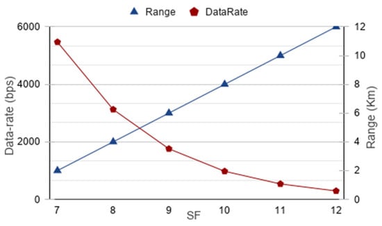
Figure 1.
Range versus data-rate in different Spreading Factors (SFs) [21].
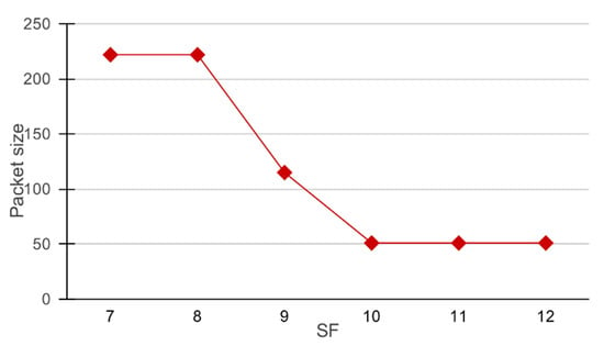
Figure 2.
Spreading Factor (SF) versus maximum packet size in LoRa.
The smart meters require a long-range and low communication rate, making LoRa a perfect choice for this application. There are some communication modules, like Libelium SX1272, which uses LoRa modulation and provides optional frequency bands, coding rates, and transmission rates [19,22]. Nowadays, LoRa technology is widely used for Internet of Things (IoT) purposes [23]. The IoT devices represent a network of interconnected devices. It is estimated that, by the next decade, the number of these devices will reach about 125 billion. Currently, IoT devices use LoRa technology widely, especially in sectors like electricity and agriculture, and in automation purposes, due to their long-range communication capabilities [1,24]. Due to its numerous features like low power-usage, long-range, and adaptive data rate capability, LoRa has a wide range of applications. Figure 3 shows the different areas of application of LoRa with specific applications [25,26].
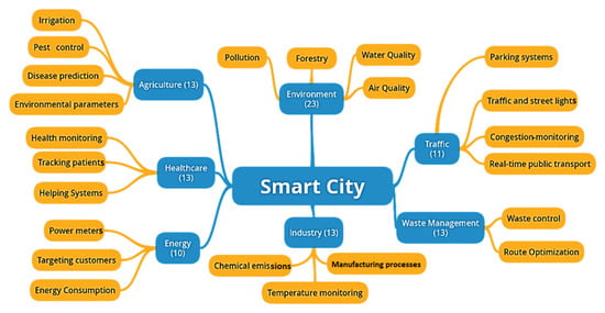
Figure 3.
Application of LoRaWAN.
Regarding these applications, a LoRa end device directly communicates with the gateway to transfer the data to the cloud. Each end device should be placed within the range of the gateway for a successful transfer of data. Taking a higher layer perspective, the current application of LoRa uses stars-of-stars topology that permits the end nodes to connect to the gateways through direct links, as shown in Figure 4 [27,28]. The most common architecture of the LoRaWAN used nowadays can be seen in Figure 4.
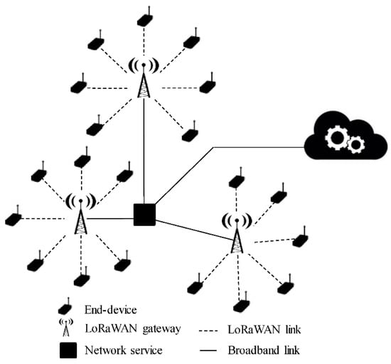
Figure 4.
Stars-of-stars topology.
A LoRa network is typically setup in a stars-of-stars topology where gateways pick up the message broadcasted by the end-devices or nodes and forward them over an internet protocol-based network to a network server. A network server is a software application running over one or more servers. The network servers have the knowledge of nodes and their owners. The messages are encrypted and can only be decrypted by the destination node or the network server [7]. LoRaWAN devices are mainly used in three operation modes depending upon the energy consumption and download speed. The Class A devices offer greater energy saving, since they stay in sleep mode most of the time and are just able to receive transmissions after each uplink connection by opening a listening window. Class B devices have default reception windows within the gateway, and the Class C devices are continuously listening to the channel so they can receive a downlink connection at any time [25,27,28].
LoRaWAN is one of the examples of a Low Power Wide Area Network (LPWAN) technology that appears to be very suitable for smart metering thus, the LoRaWAN can be used to create a mesh network for smart metering. It is a novel modulation technique that enables it to communicate over long distances and it has over 50 communication channels. The LoRa architecture consists of LoRa devices, gateways, and an application server, as shown in Figure 5 [29]. The function of a LoRa device is to read the sensor data and transmit it to the gateway for further operation. The LoRa device also is able to read the commands from the gateway and respond accordingly. A gateway is connected to multiple devices, whose function is to establish the communication between the LoRa devices and the application server. The application server manages the collected data from all the devices [13,29]. Figure 6 shows the star topology of the LoRaWAN, in which each node is connected to the network with the help of gateways. A gateway is placed at an appropriate location where all of the required nodes can connect to it. All the nodes send their data to the gateway, and the gateway uploads the data to the cloud [7]. The star topology is useful when it is feasible to place multiple gateways at required locations. Concerning the case of rural areas where the internet is not available, the proposed systems may fail to operate successfully. Hence, to solve this problem, the LoRa-based mesh network is suitable for the case of remote areas. Regarding a mesh network, each node can act as a repeater to relay information to the neighboring node, so in the case of the meters where gateway signals cannot reach, the meters in between them act as a bridge to fill the communication gap [5,24].
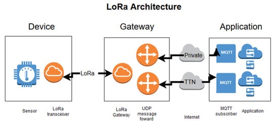
Figure 5.
Architecture of LoRa technology.
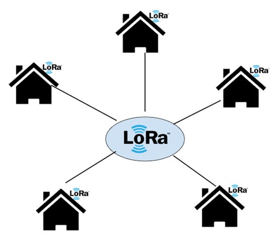
Figure 6.
LoRaWAN star topology.
3. Method
LoRaWAN has been purposed in many previous research works to be implemented for smart metering in which a stars-of-stars topology was used [24,30,31]. Stars-of-stars topology can be implemented in urban areas where gateways can be placed in convenient places. However, in rural areas where gateways cannot be placed at required locations due to the unavailability of a reliable communication infrastructure using mesh topology in such situations allows for flexible placement locations for gateways, and also allows for a larger coverage area. Mesh architecture helps to increase the range of the LoRa network. LoRa based infrastructure can be deployed and operated at a lower cost than previously discussed technologies, which addresses the limitation of previously discussed communication methods regarding smart metering. Using mesh configuration, rather than installing additional nodes for hard-to-reach places, allows intermediate nodes to be used to relay information to the gateway. A LoRa mesh-based smart metering system will form an interconnected mesh of smart meters. When there is a connection between a smart meter and a gateway, it directly sends the data to the gateway, otherwise it uses intermediate nodes to connect to the gateway.
First, during the simulation, smart meters were installed in the respective locations and, if any smart meter was not able to connect itself to the network after the installation, a relay node was installed by manually selecting a suitable location. Regarding hard-to-reach meters, the intermediate nodes were placed to connect the gateways. Figure 7 shows the purposed architecture for smart metering, Figure 8 shows how the networks can be formed depending upon the node density to reduce interference between the neighboring networks, and Figure 9 shows the simulated sample network of 20 nodes. To verify the required specifications of the LoRa mesh network for smart metering purposes, the simulation-based analysis of LoRa mesh topology was performed in the network simulation 2 (NS2) simulator. A simulation to determine the response of the network regarding the packet delivery ratio (PDR) and the end–end delay with an increase in the number of nodes was performed, and how the PDR was affected by the packet size was determined. The area of the simulation environment was considered to be 20 × 20 km2. The LoRa has a data transfer speed from 146.1 bps to 45,660 bps, depending upon the spreading factor (SF) and modulation technique [18]. According to a study, it was found that an average smart meter generates and receives traffic of 3185 and 272 bytes per day [32], respectively. Simulations were done to determine whether the network could satisfy these conditions. Figure 10, Figure 11, Figure 12 and Figure 13 show the flowcharts of the programs that were implemented in the nodes and gateways.
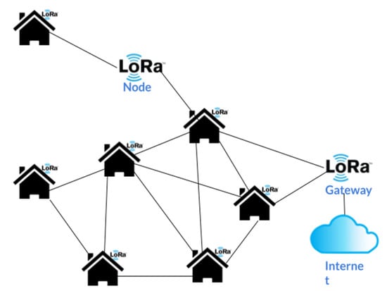
Figure 7.
LoRaWAN mesh architecture.
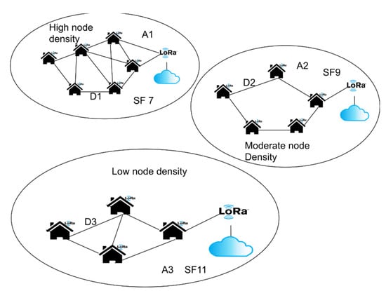
Figure 8.
Network management in large scale.
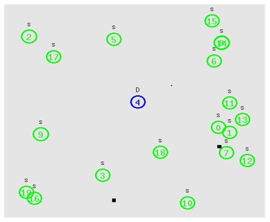
Figure 9.
Network simulation 2 NS2 simulation.
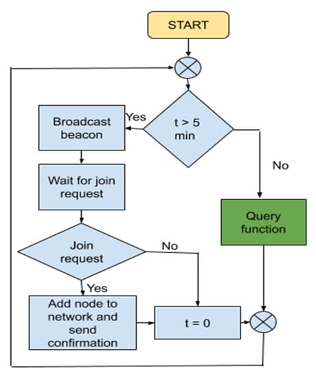
Figure 10.
Operation of a Gateway.
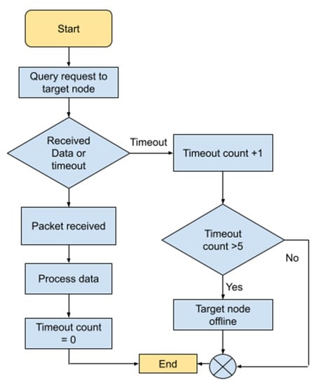
Figure 11.
Query function.
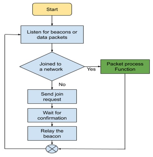
Figure 12.
Operation of a Node.
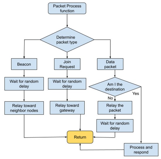
Figure 13.
Packet process function.
Depending upon the location of the application, the node density and number of nodes in the network are going to be different. When the application area is rural, the density of houses is going to be low, so the distance between nodes will be large and a higher SF needs to be used. Similarly, for an urban area, a lower SF needs to be used. When a network size becomes too large, the network will not be able to meet the number of data packets to be extracted per day. Considering such a case, the network either has to decrease the SF to increase the network speed or split the network in two. When a network needs to be split in two, the two neighboring networks will have to use different channels and SFs, depending upon the size and density of the network, to avoid interference, as shown in Figure 8. Regarding Figure 8, three networks with a different number of nodes are shown where A1, A2, and A3 are the areas of the nodes and D1, D2 and D3 are the average distance between the nodes in respective networks. (A1 < A2 < A3 and D1 < D1 < D3). It shows that the network in which nodes were closely packed could support a large number of nodes because they used a low SF, which allowed them to use a higher speed. Concerning a network in which nodes were far apart, they had to use a higher SF, which could support fewer nodes.
The simulation was done for an area of 20 × 20 km2 for different SFs in different node density conditions. The geographic nature of the application area was considered flat while performing the simulation. Environmental conditions like clouds, mist, and humidity were not taken into account due to their everchanging nature. The range and data rate of each node in the simulation were defined according to the data in Figure 1. Figure 9 shows the instance of simulation of 20 nodes in a mesh configuration in the NS2 network simulator.
The mesh network considered for the simulation contained a central gateway and nodes. The function of the central gateway was to generate invitation beacons to register new nodes to the network. The gateway used an algorithm to generate the beacon signals periodically, as shown in Figure 10. Once it generated an invitation beacon, it waited and listened to join the requests from the nodes. When it received join requests, it added the node to the network and sent the confirmation signal to the corresponding node. It also sent query requests to nodes for data packets.
Then, the gateway was used to connect the network to the internet. Shown in Figure 10, the function of the gateway was to periodically broadcast invitation beacons that registered the new nodes to the network and execute the data query function to extract data from the respective nodes as required. Similarly, the query function sent query requests to the target nodes turn-by-turn to extract data from the respective nodes, as shown in Figure 11. When the target node did not respond to the query request within a time limit, then the target node was considered offline and the algorithm moved on to the other nodes for data extraction.
Conversely, the nodes were always listening to the beacons, data packets, and/or join requests, as shown in Figure 12. When a node received a beacon: (a) if it was already connected to the network, it executed the packet processing function; (b) if not, it connected itself to the network by sending join requests to the gateway. The nodes were programmed in such a way that, while retransmitting a beacon, they updated and included the path through which the beacon arrived at that particular node. Therefore, when sending the join request, it used the path included in the beacon to define the path of the join request signal. Then it waited for the confirmation from the gateway, got the confirmation that it was registered to the network and retransmitted the invitation beacon signal. While retransmitting the beacon, it also included the path from which the beacon was received so the receiving nodes knew the path through which to respond to the gateway. When the node was already registered to the network, it executed the packet process function. Shown in Figure 13, the task of the packet process function was to determine what type of data packet was the received signal. When it was a beacon, it waited for the random delay, included the updated path of the arrival of the beacon, waited for a random time, and retransmitted the signal along with the updated path. When it was a join request from a node then it read the path to the gateway from the received signal and relayed the signal according to the path. Similarly, if it was a data request signal from the gateway then it determined the target node; if it was the target node then it sent the requested data packet to the gateway. When it was not the target node, then it retransmitted the signal accordingly.
4. Results and Discussion
Here, a mesh network of LoRa devices was simulated using an NS2 network simulator, and the LoRa frequency used was 912 MHz at a 125 kHz bandwidth. The capacity of the network was analyzed for different Spreading Factors (SFs). The analysis was done to determine whether the network could be used for smart metering with standard smart metering requirements. A network was simulated for different speeds from 146 bps to 5469 bps for an area of 20 × 20 km2 and a buffer size of 512 bytes for each node, where data extraction was done periodically. The range and speed of each node were defined according to Table 1, and the nodes were positioned randomly in the simulated area.
Figure 14 presents the end-to-end delay of the transmitted signal for different SFs with a different number of nodes. It shows how the average end-to-end delay of signal transmission increased with an increase in several nodes in a network, and how the end-to-end delay also varied with the different SFs. Each data in Figure 14 is an average of 25 transmissions while collecting data at a 20-s interval. Figure 15 shows how the package delivery ratio (PDR) changed and Figure 14 shows how the end-to-end delay changed with the change in SF and the number of nodes. Considering Figure 15, it can be seen that, although at a lower SF and a low number of nodes, the PDR was high but, with the increase in SF and the number of nodes, the PDR decreased rapidly. Due to the decrease in the PDR with respect to the increase in SF and nodes in the network, the gateway had to send multiple data requests to the respective node to get a single packet extracted successfully. Even with the decrease in the PDR, regarding Figure 16 it can be seen that the minimum successful data extraction period for a SF of 12 and a network of 250 nodes was 750 s, which is more than enough for smart metering purposes [21,24]. Figure 16 shows how the minimum possible data extraction period varied for a node if the master node extracted the data from each node turn-by-turn. It can be seen in Figure 16 that, with the increase in the number of nodes and SF, the minimum successful data extraction period increased accordingly. Regarding a network consisting of 250 nodes and operating at a SF of seven, the minimum successful data extraction period will be 230 s.
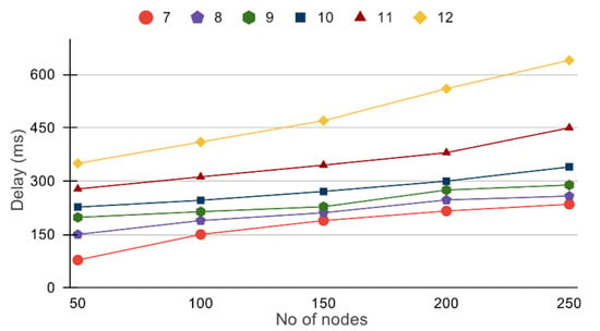
Figure 14.
Number of nodes versus end–end delay.
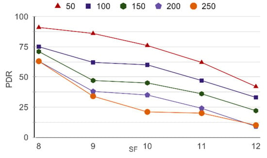
Figure 15.
SF versus PDR for a different number of nodes.
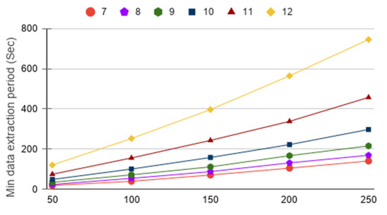
Figure 16.
Minimum data extraction period for a different number of nodes at different Spreading Factors (SFs).
Similarly, for a SF of 11, the data extraction period will be 435 s. When a network is not meeting the minimum data extraction period requirement, then we either need to decrease the SF or split the network into two separate networks. When there is a condition where the network needs to be split into two, then it needs to be done in such a way that the signals do not interfere with each other. Regarding signal interference reductions between neighboring networks, they can be assigned different SFs, or they can be divided in terms of geographical terrain for minimum signal interference. Considering the simulation, a minimum time interval at which nodes can communicate with the gateway is calculated and presented in Figure 16.
An average meter generates traffic of 3185 bytes per day and receives 227 bytes per day [21]. According to the studies [21,24], an average meter can generate 3.185 Kbytes of data per day. It will take a different number of transmissions to satisfy 3.185 Kbytes of data per day per node based upon the SF of the node due to different packet size capacities at different SFs, as shown in Figure 17. Taking these factors into consideration, a minimum number of transmissions required per day for networks consisting of different SFs is obtained and shown in Figure 18. It can be observed that the maximum number of packet transmissions required at the lowest data rate was 62 bps. This condition is met even by a network consisting of the lowest data rate. Regarding the simulated network size, the network easily meets the required conditions for smart metering. The above data suggests that the mesh network of LoRa devices can be used for smart metering purposes.
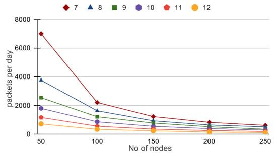
Figure 17.
Packet per day versus number of nodes in different SF.
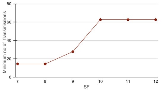
Figure 18.
Minimum number of transmissions required per node for networks consisting of different Spreading Factors (SFs).
5. Conclusions
This paper discussed how LoRa devices can be used for smart metering. The study proposed a mesh configuration of LoRa devices be implemented in a smart metering system. The study evaluated the algorithm to be used by gateways and nodes to rout and manage data packets based on a simulation. The simulation results verified how the system will perform when implemented for smart metering purposes under various conditions like different Spreading Factors (SFs) and nodes. Based on the results, we found that the LoRaWAN in a mesh configuration achieves the required specifications to be implemented for smart metering in rural microgrids (MGs).
The simulation does not consider conditions like non-uniform geographical terrain and external noise, however, so the system may behave a little differently in real implementation. During this analysis, the maximum number of devices simulated in a mesh were 250, for which the purposed system meets the required specifications from the simulation. Once the system reaches a critical number of smart meters in a network, the system will not be able to maintain the required specifications due to the limited bandwidth of LoRa devices. Further studies need to be conducted to address these issues. However, the proposed method can be implemented even in areas where no commercial communications systems are available. It requires less deployment cost as it minimizes the number of gateways by using mesh topology. Furthermore, the operational cost of the proposed concept is significantly less compared to the traditional approaches as the traditional approaches involve external communication service providers.
Author Contributions
Conceptualization, A.M., Y.R. and A.S. (Ashish Shrestha); methodology, A.M., Y.R. and A.S. (Ajay Singh); software, A.M. and Y.R.; validation, A.T., P.K. and S.S.; formal analysis, A.M. and Y.R.; investigation, A.M. and Y.R.; resources, A.S. (Ashish Shrestha) and A.T.; writing—original draft preparation, A.M., Y.R., A.S. (Ashish Shrestha) and A.S. (Ajay Singh); writing—review and editing, A.M., Y.R., A.S. (Ashish Shrestha), A.S. (Ajay Singh), A.T., F.G.-L., P.K., S.S. All authors have read and agreed to the published version of the manuscript.
Funding
This research was funded by EnergizeNepal Project Office, Kathmandu University, grant number ENEP-RENP-II-19-03, and the APC was provided by Seokjoo Shin.
Data Availability Statement
Data related to this research is available on [33].
Acknowledgments
The authors are thankful to the Department of Electrical and Electronics Engineering and Center for Electric Power Engineering (CEPE), Kathmandu University to provide the requested information, laboratory supports, and kind cooperation during this research work.
Conflicts of Interest
There are no conflict of interest.
References
- Rahman, M.M.; Islam, M.O.; Salakin, M.S. Arduino and GSM based smart energy meter for advanced metering and billing system. In Proceedings of the 2015 International Conference on Electrical Engineering and Information Communication Technology (ICEEICT), Savar, Bangladesh, 21–23 May 2015; pp. 1–6. [Google Scholar]
- Uribe-Pérez, N.; Hernández, L.; De la Vega, D.; Angulo, I. State of the art and trends review of smart metering in electricity grids. Appl. Sci. 2016, 6, 68. [Google Scholar] [CrossRef]
- Depuru, S.S.S.R.; Wang, L.; Devabhaktuni, V.; Gudi, N. Smart meters for power grid—Challenges, issues, advantages and status. In Proceedings of the 2011 IEEE/PES Power Systems Conference and Exposition, Phoenix, AZ, USA, 20–23 March 2011; pp. 1–7. [Google Scholar]
- Shrestha, A.; Bishwokarma, R.; Chapagain, A.; Banjara, S.; Aryal, S.; Mali, B.; Thapa, R.; Bista, D.; Hayes, B.P.; Papadakis, A. Peer-to-Peer Energy Trading in Micro/Mini-Grids for Local Energy Communities: A Review and Case Study of Nepal. IEEE Access 2019, 7, 131911–131928. [Google Scholar] [CrossRef]
- Wibisono, G.; Saktiaji, G.P.; Ibrahim, I. Techno economic analysis of smart meter reading implementation in PLN Bali using LoRa technology. In Proceedings of the 2017 International Conference on Broadband Communication, Wireless Sensors and Powering (BCWSP), Jakarta, Indonesia, 21–23 November 2017; pp. 1–6. [Google Scholar]
- Das, H.; Saikia, L. GSM enabled smart energy meter and automation of home appliances. In Proceedings of the 2015 International Conference on Energy, Power and Environment: Towards Sustainable Growth (ICEPE), Shillong, India, 12–13 June 2015; pp. 1–5. [Google Scholar]
- Laveyne, J.; Van Eetvelde, G.; Vandevelde, L. Application of LoRaWAN for smart metering: An experimental verification. Int. J. Contemp. Energy 2018, 4, 61–67. [Google Scholar]
- Shrestha, A.; Rana, L.B.; Singh, A.; Phuyal, S.; Ghimire, A.; Giri, R.; Kattel, R.; Karki, K.; Jha, S.K. Assessment of electricity excess in an isolated hybrid energy system: A case study of a Dangiwada village in rural Nepal. Energy Procedia 2019, 160, 76–83. [Google Scholar] [CrossRef]
- Shrestha, A.; Singh, A.; Khanal, K.; Maskey, R. Potentiality of off-grid hybrid systems for sustainable power supply at Kathmandu University campus. In Proceedings of the 2016 IEEE 6th International Conference on Power Systems (ICPS), New Delhi, India, 4–6 March 2016; pp. 1–6. [Google Scholar]
- Shrestha, P.; Shrestha, A.; Adhikary, B. Comparative analysis of grid integration on distributed energy system. In Proceedings of the 5th International Conference on Developments in Renewable Energy Technology, Kathmandu, Nepal, 29 March 2018; pp. 29–31. [Google Scholar]
- Sah, S.; Shrestha, A.; Papadakis, A. Cost-effective and reliable energy system for Kathmandu University complex. In Proceedings of the 11th International Conference on Deregulated Engineering Market Issues, Nicosia, Cyprus, 20–21 September 2018; pp. 20–21. [Google Scholar]
- AEPC. A Year in Review. Available online: https://www.aepc.gov.np/uploads/docs/2018-06-20_Annual%20Report%20FY%202069-070%20(2012-2013).pdf (accessed on 10 August 2020).
- Shrestha, A.; Rajbhandari, Y.; Khadka, N. Status of Micro/Mini-Grid Systems in a Himalayan Nation: A Comprehensive. IEEE Access 2020, 8, 120983–120998. [Google Scholar] [CrossRef]
- Shrestha, P.; Shrestha, A.; Shrestha, N.T.; Papadakis, A.; Maskey, R.K. Assessment on Scaling-Up of Mini-Grid Initiative: Case Study of Mini-Grid in Rural Nepal. Int. J. Precis. Eng. Manuf. Green Technol. 2021, 8, 217–231. [Google Scholar] [CrossRef]
- Badran, O.; Mekhilef, S.; Mokhlis, H.; Dahalan, W. Optimal reconfiguration of distribution system connected with distributed generations: A review of different methodologies. Renew. Sustain. Energy Rev. 2017, 73, 854–867. [Google Scholar] [CrossRef]
- Georgilakis, P.S.; Hatziargyriou, N.D. A review of power distribution planning in the modern power systems era: Models, methods and future research. Electr. Power Syst. Res. 2015, 121, 89–100. [Google Scholar] [CrossRef]
- Marahatta, A.; Rajbhandari, Y.; Shrestha, A.; Singh, A.; Gachhadar, A.; Thapa, A. Priority-based low voltage DC microgrid system for rural electrification. Energy Rep. 2021, 7, 43–51. [Google Scholar] [CrossRef]
- Reynders, B.; Meert, W.; Pollin, S. Power and spreading factor control in low power wide area networks. In Proceedings of the 2017 IEEE International Conference on Communications (ICC), Paris, France, 21–25 May 2017; pp. 1–6. [Google Scholar]
- Petäjäjärvi, J.; Mikhaylov, K.; Pettissalo, M.; Janhunen, J.; Iinatti, J. Performance of a low-power wide-area network based on LoRa technology: Doppler robustness, scalability, and coverage. Int. J. Distrib. Sens. Netw. 2017, 13, 1550147717699412. [Google Scholar] [CrossRef]
- Semtech. Tech Papers and Guides. Available online: https://lora-developers.semtech.com/library/tech-papers-and-guides/lora-and-lorawan/ (accessed on 10 January 2021).
- Alliance, L. A Technical Overview of LoRaWAN. Available online: https://www.tuv.com/media/corporate/products_1/electronic_components_and_lasers/TUeV_Rheinland_Overview_LoRa_and_LoRaWANtmp.pdf (accessed on 10 November 2015).
- Libelium. Waspmote—LoRa 868MHz 915MHz—SX1272 Networking Guide. Available online: https://usermanual.wiki/Document/waspmotelora868mhz915mhzsx1272networkingguide.548782060/html (accessed on 10 February 2017).
- Sarker, V.K.; Queralta, J.P.; Gia, T.N.; Tenhunen, H.; Westerlund, T. A survey on LoRa for IoT: Integrating edge computing. In Proceedings of the 2019 Fourth International Conference on Fog and Mobile Edge Computing (FMEC), Rome, Italy, 10–13 June 2019; pp. 295–300. [Google Scholar]
- Cheng, Y.; Saputra, H.; Goh, L.M.; Wu, Y. Secure smart metering based on LoRa technology. In Proceedings of the 2018 IEEE 4th International Conference on Identity, Security, and Behavior Analysis (ISBA), Singapore, 11–12 January 2018; pp. 1–8. [Google Scholar]
- Andrade, R.O.; Yoo, S.G. A comprehensive study of the use of LoRa in the development of smart cities. Appl. Sci. 2019, 9, 4753. [Google Scholar] [CrossRef]
- Cattani, M.; Boano, C.A.; Römer, K. An experimental evaluation of the reliability of lora long-range low-power wireless communication. J. Sens. Actuator Netw. 2017, 6, 7. [Google Scholar] [CrossRef]
- Sanchez-Iborra, R.; Sanchez-Gomez, J.; Ballesta-Viñas, J.; Cano, M.-D.; Skarmeta, A.F. Performance evaluation of LoRa considering scenario conditions. Sensors 2018, 18, 772. [Google Scholar] [CrossRef]
- Pasolini, G.; Buratti, C.; Feltrin, L.; Zabini, F.; De Castro, C.; Verdone, R.; Andrisano, O. Smart city pilot projects using LoRa and IEEE802. 15.4 technologies. Sensors 2018, 18, 1118. [Google Scholar] [CrossRef] [PubMed]
- TTN LoRa Architecture. Available online: https://things4u.github.io/Projects/SingleChannelGateway/DeveloperGuide/1_LoRa_Architecture/architecture.html (accessed on 1 June 2016).
- Varsier, N.; Schwoerer, J. Capacity limits of LoRaWAN technology for smart metering applications. In Proceedings of the 2017 IEEE International Conference on Communications (ICC), Paris, France, 21–25 May 2017; pp. 1–6. [Google Scholar]
- Helder, F.; Dester, P.S.; Stancanelli, E.M.G.; Cardieri, P. Feasibility of Alarm Events upon Smart Metering in LoRa Networks. In Proceedings of the 2019 16th International Symposium on Wireless Communication Systems (ISWCS), Oulu, Finland, 27–30 August 2019; pp. 480–484. [Google Scholar]
- Luan, W.; Sharp, D.; LaRoy, S. Data traffic analysis of utility smart metering network. In Proceedings of the 2013 IEEE Power & Energy Society General Meeting, Vancouver, BC, Canada, 21–25 July 2013; pp. 1–4. [Google Scholar]
- Marahatta, A. LoRa Data. 2021. Available online: https://github.com/anpmht/Lora_data (accessed on 10 January 2021).
Publisher’s Note: MDPI stays neutral with regard to jurisdictional claims in published maps and institutional affiliations. |
© 2021 by the authors. Licensee MDPI, Basel, Switzerland. This article is an open access article distributed under the terms and conditions of the Creative Commons Attribution (CC BY) license (http://creativecommons.org/licenses/by/4.0/).