Article

Novel Switching Frequency FCS-MPC of PMSG for Grid-Connected Wind Energy Conversion System with Coordinated Low Voltage Ride Through

by
Asmaa A. Ghany
1,2,
E. G. Shehata
1,
Abo-Hashima M. Elsayed
1,
Yahia S. Mohamed
1,
Hassan Haes Alhelou
3,4,*,
Pierluigi Siano
5,* and
Ahmed A. Zaki Diab
1,*
1
Department of Electrical Engineering, Minia University, Minia 61111, Egypt
2
Department of Electrical Engineering, Beni-Suef University, Beni-Suef 62521, Egypt
3
School of Electrical and Electronic Engineering, University College Dublin, Belfield, Dublin 4, Ireland
4
Department of Electrical Power Engineering, Tishreen University, 2230 Lattakia, Syria
5
Department of Management & Innovation Systems, University of Salerno, 84084 Salerno, Italy
*
Authors to whom correspondence should be addressed.
Electronics 2021, 10(4), 492; https://doi.org/10.3390/electronics10040492
Submission received: 23 January 2021 / Revised: 8 February 2021 / Accepted: 16 February 2021 / Published: 19 February 2021
(This article belongs to the Special Issue Voltage Stability of Microgrids in Power Systems)

Abstract

:
The integration of wind energy systems (WECS) into the power grid through power electronic converters should ensure the high performance of the control system. In spite of several advantages of conventional Finite control set-model predictive controller (FCS-MPC), variable switching frequency and high computational burden are considered its main drawbacks. In this paper, a fast FCS-MPC of a machine side converter (MSC) of direct-driven permanent magnet synchronous generator (PMSG) based wind turbines for wind energy conversion system is proposed. The wind energy conversion system has been realized using a direct driven PMSG and a full-scale back-to-back power converter. The proposed controller is designed to reduce the required calculations in each horizon. In addition, the performance of conventional FCS-MPC is compared with the proposed method, and an improvement in total harmonic distortion spectra and simulation time required even when imposing a lower sampling frequency was found. To overcome the variable switching frequency problem, a modulation algorithm is introduced in the minimization process of modulated FCS-MPC. To keep the proposed system attached to the utility during a fault, a coordinated pitch angle control and low voltage-ride through (LVRT) algorithm is designed and inserted in the vector control of the grid side converter (GSC) to supply reactive power to the grid during fault for ensuring safe operation of the inverter and meeting the grid code requirements. The effectiveness of the proposed controller is illustrated using simulation results under different operating conditions.

1. Introduction

The generation of wind power has been increasing rapidly in the last years. An adjustable speed wind energy conversion system (WECS) mostly includes a doubly fed induction generator (DFIG) and direct-driven permanent magnet synchronous generator (PMSG) full power converter. PMSG has many benefits in comparison with DFIG because of the elimination of the gearbox and the full decoupling between the grid and the generator [1]. Different control strategies have been submitted to regulate the generated power of PMSG. Field oriented control (FOC) and direct power control (DPC) are the most prevalent control strategies now. Despite good steady-state and dynamic performance of FOC, it is complicated due to PI tuning problems. On the other hand, DPC provides good performance, simplicity of control structure, and robustness against control parameter variations. However, the harmonic spectrum of the output current is large and its variable switching frequency complicates filter design [2,3].
For the above-mentioned reasons, Model predictive control (MPC) has recently been introduced [4,5,6]. MPC has various advantages, including simple control, absence of modulator, fast dynamic response, and ability to overcome non-linearity and multi-objectives control problems [7,8,9]. In [7], a model predictive based on direct power control for multi-objectives control has been introduced, which merges the converter switching frequency, minimizing power deviation and manipulates the system stability. Furthermore, A direct torque MPC model for multi-objective control is designed in [8] for decreasing the converter switching frequency and ripples of flux and torque of induction motors. In [9], a virtual flux evaluation based on direct power MPC is presented.
Finite control Set MPC (FCS-MPC) is commonly used for power converters control. Its concept is to predict the response of the system for each switching state, then evaluating a cost function and the switching state that provides minimum cost function will be taken as an optimum wherefore it is applied for the next control cycle. FCS-MPC provides easy implementation and online optimization, so it is applied in power and torque control of induction motors and grid power converters [8,9,10,11].
A comparative study of sliding mode controller, FCS-MPC, and PI controller schemes for machine side converter based on rotor flux orientation of PMSG has been presented in [12]. Despite its several merits, variable switching frequency, large harmonic content in the current and high computational burden are considered its main drawbacks [13,14,15,16]. Many solutions have been introduced to fix the switching frequency and reduce harmonic content of conventional FCS-MPC [14,15,16]. In [14], FCS-MPC for two-level grid connected converters operating with constant switching frequency has been accomplished through an optimal switching sequence of DPC. In [15], a constant switching frequency in FCS-MPC for the three-phase active-front-end rectifiers is studied; however, the proposed method is complex and needs large calculations of voltage converters. In [16], a Multiple-Vector FCS-Model Predictive Power Control is introduced for the grid-side converter control. Three types of FCS-MPC schemes with duty cycle optimizations are compared.
To obtain good and fast steady-state performance of FCS-MPC, the computational load needs to be released and the time of real implementation should not constitute a high percentage of the switching time for the sake of other functions accommodation such phase locked loop (PLL) and maximum power tracking. It is expected that the implementation duration using digital signal processing (DSP) or microcontroller is limited to 100 μs. Thus, for FCS-MPC algorithm, at least 52 μs is required for online calculations and evaluation of cost function and this will be time consuming. So, to overcome these limitations, a modulated MPC (M2MPC) with constant switching frequency and fast computation algorithm was presented in [17,18,19,20]. M2MPC is designed to control the three-phase active rectifier [17], seven-level cascade H-bridge [18,19] and matrix converter [20]. In spite of the proposed M2MPC provides fixed switching frequency, the power circuits of H-bridge and matrix converters are complex, and the proposed algorithm has a large computational load.
Because of large generated electric power from wind energy systems, so many countries have updated their grid codes to obtain a much more reliable and efficient wind power system [21,22,23,24]. The main important issue in the wind power generation is the low voltage ride through (LVRT), which is also named fault-ride through (FRT) [22]. Recently, one of the most common requirements in a wind power system is to keep the wind turbine connected to the grid during a fault without any failure and with minimum technical requirements taking only grid code specifications into account. Various research has developed methods for LVRT control [25]. In Ref. [26], a machine learning method is used where a fuzzy logic control method is applied to guarantee the grid stability as it uses the data from the wind turbine and an energy storage system to obtain a stable and reliable operation during grid fault, but it requires high installation cost and large constraints for batteries charging and discharging. The concept of LVRT is to keep the wind energy conversion system attached to the grid during system faults and to inject the system with reactive power to recover the grid from the voltage dip. PMSG wind energy system has high power extraction at different wind speeds, which enhances LVRT requirements and makes it the most promising trend for high power wind turbines [24].
In Reference [27], a multi-objective control for wind turbine power system is studied using a ranking and sorting approach without utilizing scaling factor tuning process. Meanwhile, an FCS-MPC with a small number of commutations for line current balancing is executed in [28]. However, the quality function needs to be enhanced to improve the current spectrum. Also, a model predictive direct torque control without utilizing weighting gains for PMSG wind power system is studied in [29], which reduces the computational time and overcomes the effect of parameter variations. Furthermore, a fixed switching frequency FCS-MPC algorithm synthesized by system delay compensation is applied for two-level converters in [30]. The system enhanced computational efficiency by reducing the number of sectors in the controller. An FCS-MPC for torque control based permanent magnet synchronous machine drives has been implemented in [31] to reduce the real-time implementation but, the effect of inverter switching sequence on efficiency is not considered.
To obtain a fixed switching frequency and to reduce harmonics in output waveforms of a two-level voltage source converter (VSC), a modulated FCS-MPC with constant switching frequency and fast computation is presented in this paper and compared with its conventional FCS-MPC scheme. The proposed algorithm reduces the number of sectors from six to one and this will increase the calculation efficiency. The control algorithm is applied to the generator-side converter of PMSG. Furthermore, a simplified approach for coordinated low voltage ride through capability is studied to enhance the WECS responsibility throughout the grid voltage sag. The principle of the coordinated LVRT algorithm depends on changing the active and reactive power injected in the grid-by-grid side converter during a fault in conjunction with pitch angle control to ensure that the wind speed and DC voltage is held within its constraints. In this approach, the performance of LVRT of a PMSG wind turbine is achieved without the need for hardware components since the power of PMSG is controlled by the grid power and a reactive power is delivered to support the grid voltage during fault conditions depending on grid code specifications [32]. The main contributions of this paper are as follows:
  • Overcoming the variable switching frequency of the two-level converter problem by designing a modulation algorithm that obtains a fixed switching frequency.
  • A coordinated pitch angle control and low voltage-ride through (LVRT) algorithm is designed and inserted in the vector control of the grid side converter (GSC) to supply reactive power to the grid during fault for ensuring safe operation of the inverter.
  • A comparison with conventional FCS-MPC is made to show the effectiveness of the proposed method.
This paper is arranged as follows. First, the principle of wind energy conversion system and the mathematical modeling of direct driven permanent magnet synchronous generator and grid-side converter are established. Then, the modulated model predictive control algorithm is explained in detail in comparison with conventional FCS-MPC. Finally, simulation results through a MATLAB/Simulink Package for the proposed algorithm in both steady-state and transient operation are presented to confirm the system effectiveness.

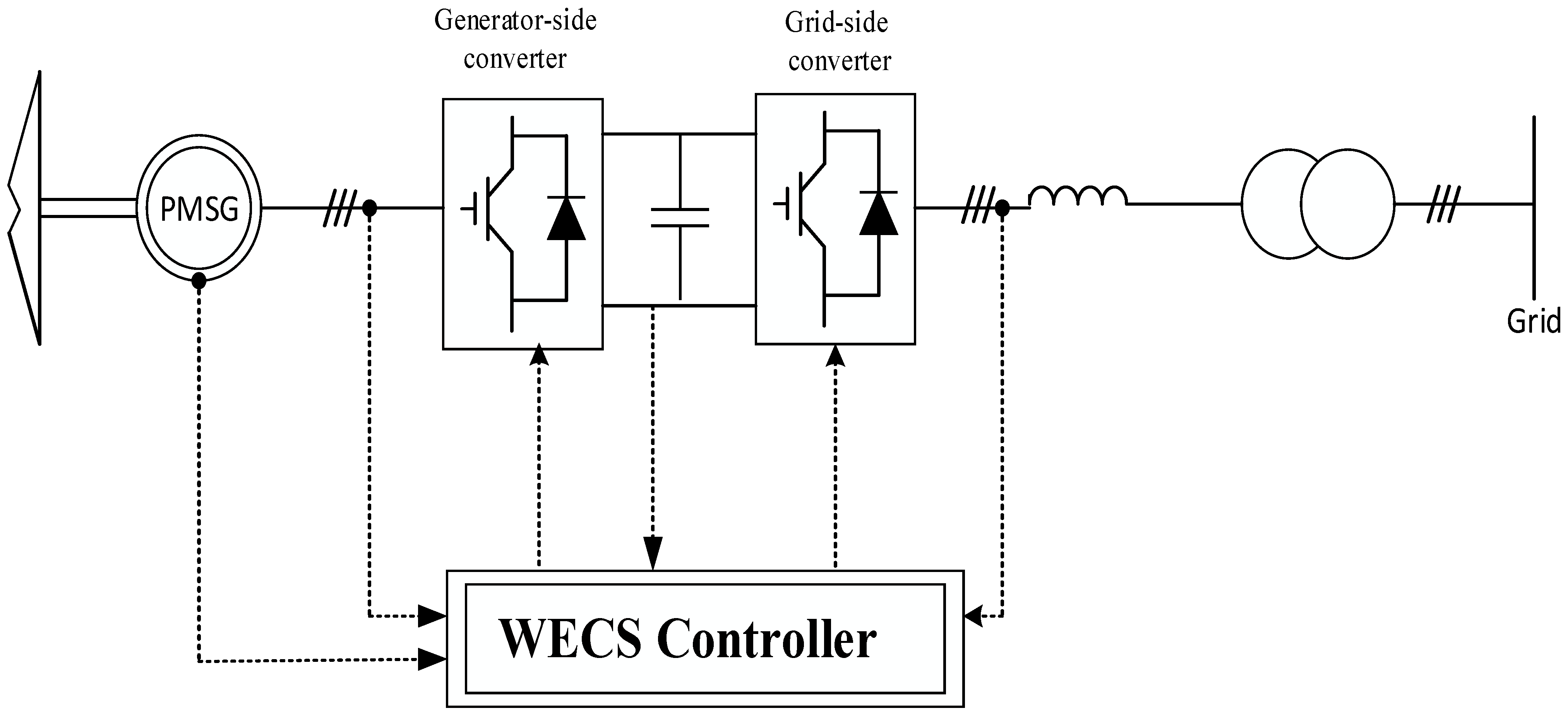
2. Principle of Wind Energy Conversion System

The single line diagram of kinetic to electric energy conversion system based on direct driven PMSG and full-scale back-to-back power converter is illustrated in Figure 1. First, kinetic energy is converted to variable frequency power via PMSG. In direct driven PMSG, the gearbox is eliminated, and the generator is directly coupled to the wind turbine system [33]. The generated power is then transferred to the power system grid after conversion to fixed frequency through AC-DC-AC converters, i.e., Machine-side Converter (MSC) and Grid-side Converter (GSC). The first one is controlled to regulate generator output power and rotational speed while the other achieves power factor control and dc-link voltage stability [1].
The mechanical power ( P m ) which can be extracted from wind turbine rotor blades rotating through an area A r with speed V w can be formulated as follows [23]:
P m = 1 2 C p A r ρ   V w 3
where ρ represents air density, and C p is the wind turbine power coefficient, which ranges between 0.32 and 0.52 according to the new generation of high-power WTs [22,23].

3. Mathematical Modeling of Direct-Driven Permanent Magnet Synchronous Generator

For the sake of simplicity, the higher-order harmonic component effect will be excluded, and the mathematical equation of PMSG in d q a x e s   rotating reference frame can be written in the following form [27]:
V s d = R s   i s d + d φ s d d t ω e   φ s q
V s q = R s   i s q + d φ s q d t + ω e   φ s d
φ s d = L d i s d + φ r
φ s q = L q   i s q
T e = 3 2   P ( φ s d   i s q φ s q i s d )

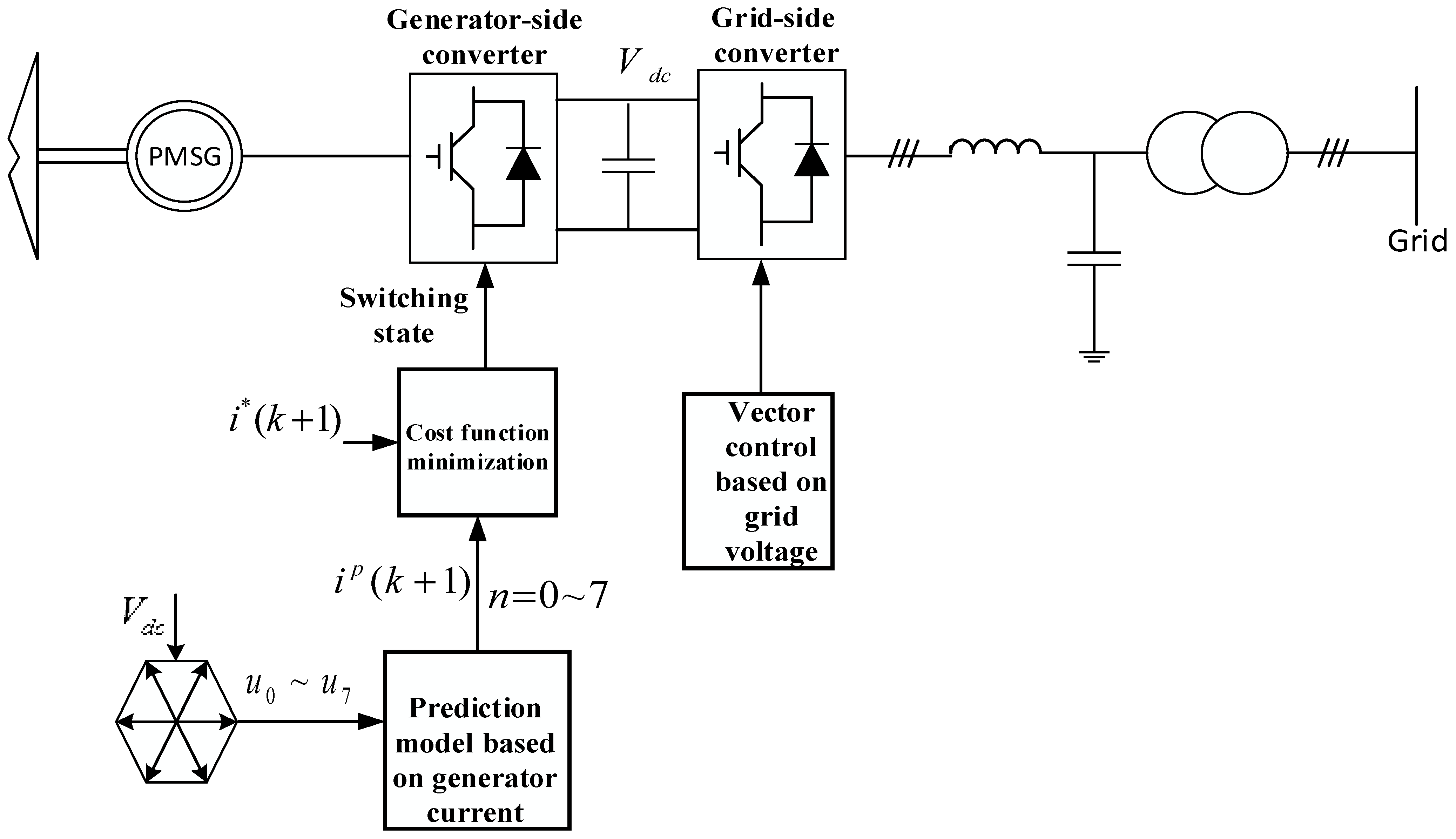
4. Modelling of Machine Side Converter

For its simplicity, a two-level three-phase converter is proposed as a machine side converter where eight switching states’ voltage vectors can be generated and are profiled in Figure 2.
By means of the switching state functions, the phase voltages can be formulated as
[ V a V b V c ] = 1 3 [ 2 1 1 1 2 1 1 1 2 ] S V d c
where the switching states of the inverter are S = [ S a S b S c ] T and
S i = { 1   i f   t h e   t o p   s w i t c h   o f   l e g   i t h   i s   O N 0   i f   t h e   b o t t o m   s w i t c h   o f   l e g   i t h   i s   O N
The output voltages in the stationary reference frame (αβ) in the term of switching states can be expressed as
[ V α V β ] = 2 3 [ 1 1 2 1 2 0 3 2 3 2 ] S V d c
Similarly, the representation of output voltages in d q   reference frame in the term of switching states is as follows
V d q = C 1 C 2 S V d c
where C 1 = [ c o s θ s i n θ s i n θ c o s θ ] and C 2 = 2 3 [ 1 1 2 1 2 0 3 2 3 2 ] .

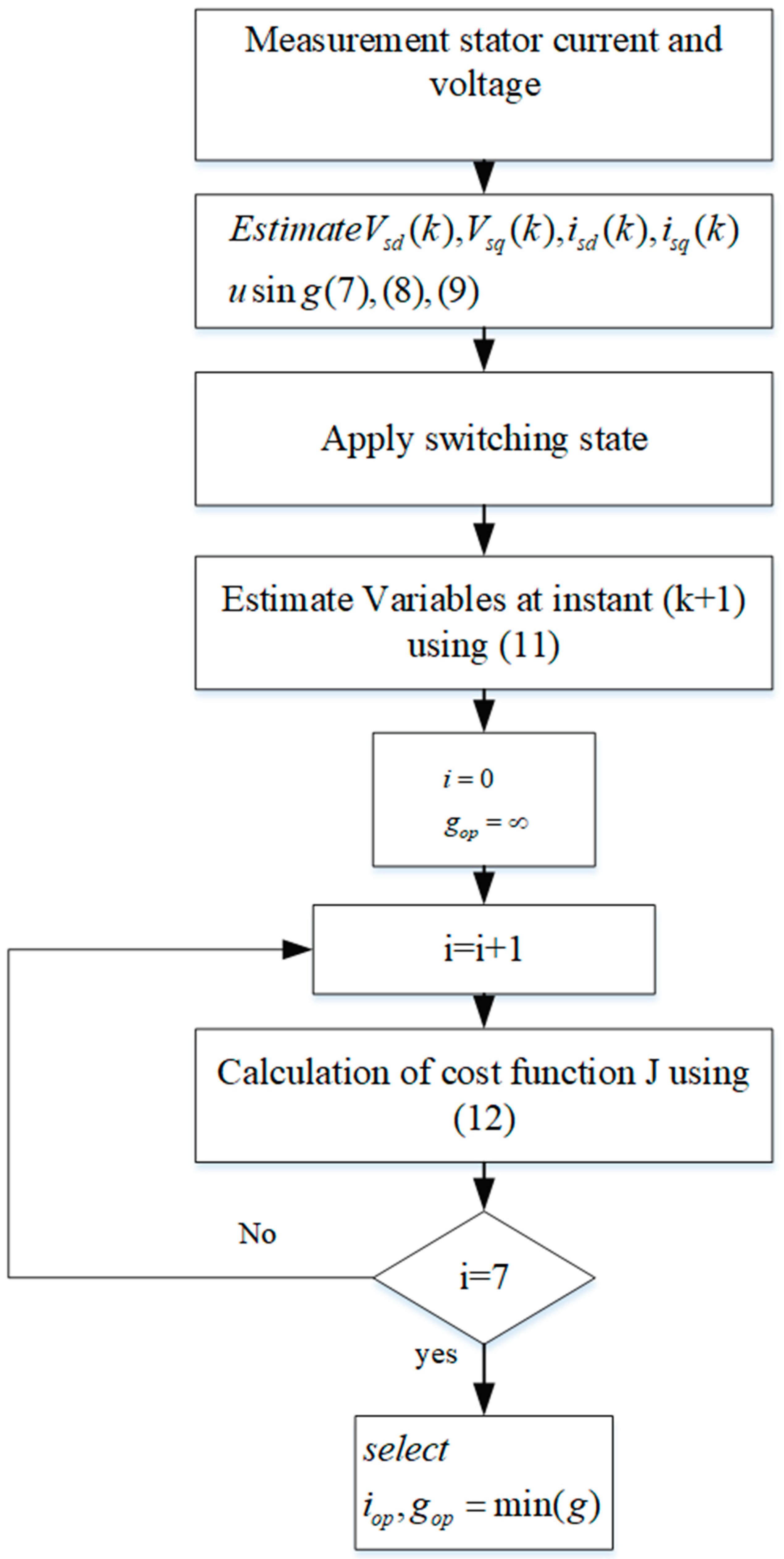
5. Conventional FCS-MPC of the MSC Scheme

Finite control set model predictive control depends on the prediction of system ability to the variation of control parameters to obtain minimum error in the next one or more sampling time. The output of this control is in a discrete form. It can be applied to the converter directly after minimizing the cost function that represents the square of the error between the reference and its predicted value of current at time instant ( k + 1 ) , as depicted in Figure 3.
The FCS-MPC uses the concept of discrete-time model to predict current values at a future sampling period. For discretization, the well-known forward Euler method with sampling time T s is applied to the time-continuous model Equations (2) and (3).
[ i s d ( k + 1 ) i s q ( k + 1 ) ] = [ 1 R s T s L d ω e L q T s L d ω e L d T s L q 1 R s T s L q ] [ i s d ( k ) i s q ( k ) ]   +   [ 0 ω e φ r T s L q ] + [ T s L d 0 0 T s L q ] [ V s d ( k ) V s q ( k ) ]
MSC model Equation (9) is combined with the discrete model of PMSG Equation (10), and the combined model can be expressed as:
[ i s d ( k + 1 ) i s q ( k + 1 ) ] = [ 1 R s T s L d ω e L q T s L d ω e L d T s L q 1 R s T s L q ] [ i s d ( k ) i s q ( k ) ] + [ 0 ω e φ r T s L q ] + [ T s L d 0 0 T s L q ] C 1 C 2 V d c
After evaluating the predictions, a cost function has to be developed to find the optimal control actions. The cost function equation of the proposed FCS-MPC is formulated as
J = ( i d * ( k + 1 ) i d ( k + 1 ) ) 2 + ( i q * ( k + 1 ) i q ( k + 1 ) ) 2
As shown in Figure 2, there are eight voltage vectors (VVs); two zero VVs and six non-zero VVs. Consequently, conventional FCS-MPC needs to evaluate eight prediction currents and eight cost functions that enlarge the computational load, especially for long step predictions [29].
The time sequence of the model predictive control for analog to digital implementation is performed in Figure 4. At sampling time ( k ) the converter is sampled by an analog to digital converter (ADC) and this process is ended at time t 1 then, the main algorithm is applied at t 2 and the switching vectors of the converter is generated at instant ( k + 1 ) . Accordingly, the voltage vectors employed at instant ( k ) is delayed and applied to the controller at instant ( k + 1 ) . In summary, the computational delay due to digital implementation through DSP or microcontroller can be compensated by shifting the discrete equations of the model one sampling time T s as will be highlighted in the next sections. A flow chart for the conventional FCS-MPC algorithm is illustrated in Figure 5.

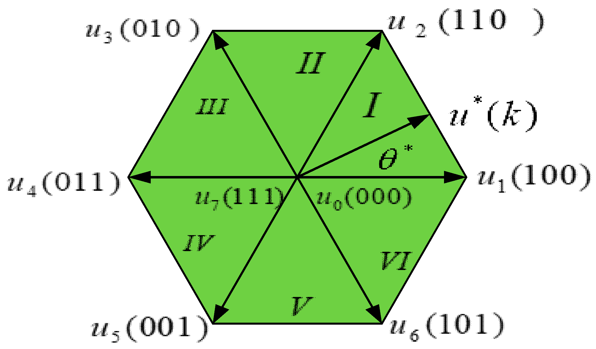
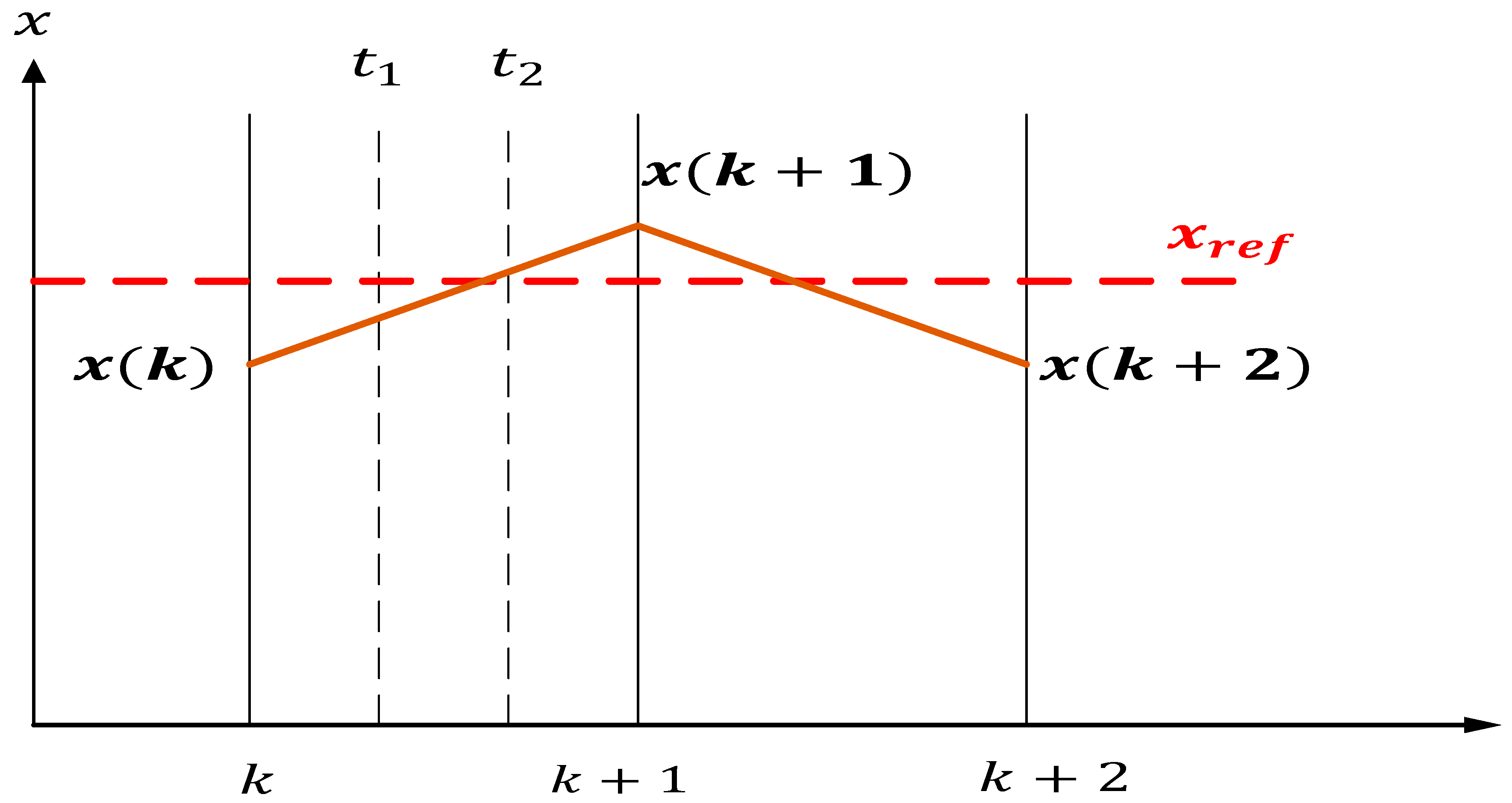
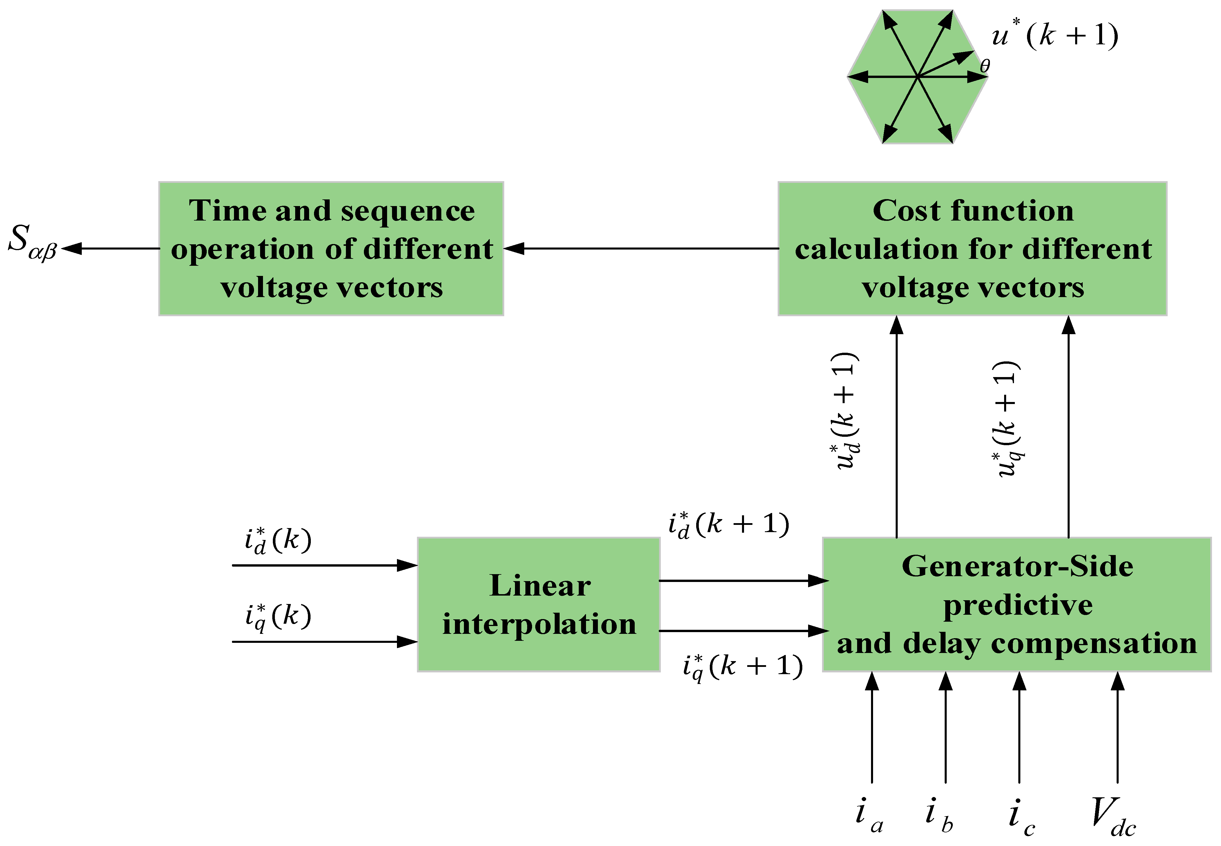
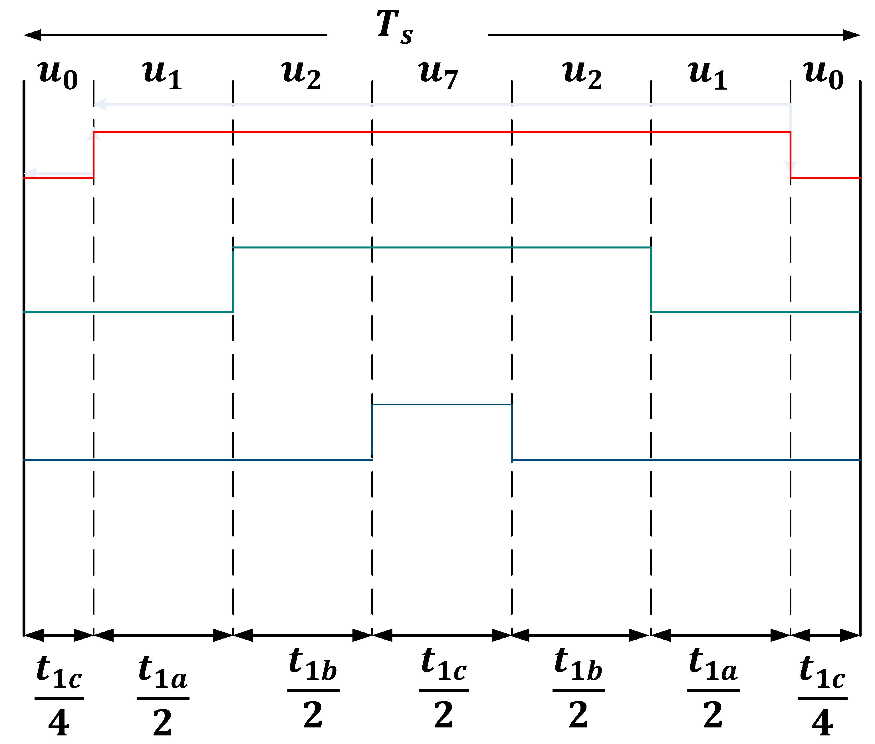
6. Proposed Modulated Model Predictive Control for the MSC

As previously described, the conventional FCS-MPC needs to repeat the calculations of the prediction current eight times during each horizon. Also, the output current contains many ripples, and the harmonic spectrum is distributed in a spread range of frequency which complicate the design of the filter [30]. So, to fix the switching frequency, modulated model predictive control MMPC is proposed. Figure 6 shows a taxonomy of the proposed MMPC for machine side converter. The d q   components of reference currents   i d * ( k + 1 ) and i q * ( k + 1 ) in rotating reference frame at instant ( k + 1 ) can be represented using linear interpolation theorem as follows:
The reference currents at instant time ( k + 1 )
i d * ( k + 1 ) = 3 i d * ( k ) 3 i d * ( k 1 ) 3 i d * ( k 2 )
i q * ( k + 1 ) = 3 i q * ( k ) 3 i q * ( k 1 ) 3 i q * ( k 2 )    
Similarly, the reference currents at instant time ( k + 2 )
i d * ( k + 2 ) = 3 i d * ( k + 1 ) 3 i d * ( k ) 3 i d * ( k 1 )    
i q * ( k + 2 ) = 3 i q * ( k + 1 ) 3 i q * ( k ) 3 i q * ( k 1 )    
The actual currents prediction at instant time ( k + 1 )
i d ( k + 1 ) = 3 i d ( k ) 3 i d ( k 1 ) 3 i d ( k 2 )      
i q ( k + 1 ) = 3 i q ( k ) 3 i q ( k 1 ) 3 i q ( k 2 )    
From the previously written equations, the predicted voltage vectors in discrete-time form which is used to obtain the future values of the output variables on one sampling time T s can be written based on normal forward Euler approximation [11,34]
[ u d * ( k + 1 ) u q * ( k + 1 ) ] = [ R s L d T s ω e   L q ω e   L d R s L q T s ] [ i d ( k + 1 ) i q ( k + 1 ) ] + [ L d T s 0 0 L q T s ] [ i d * ( k + 2 ) i q * ( k + 2 ) ] + [ 0 ω e   φ r ]
Using Equation (9), the voltage vectors of the converter according to the switching states can be expressed as:
[ u d ( k + 1 ) u q ( k + 1 ) ] = 2 3 V d c [ cos θ sin θ sin θ cos θ ] [ 1 1 2 1 2 0 3 2 3 2 ] [ S a ( k + 1 ) S b ( k + 1 ) S c ( k + 1 ) ]
To obtain a fast and perfect current tracking, the cost function based on the predicted and output voltage vectors of the converter [29]
g = | u d * ( k + 1 ) u d ( k + 1 ) | + | u q * ( k + 1 ) u q ( k + 1 ) |
For the convenience of description of the proposed MMPC to obtain fixed switching frequency, take the first sector of Figure 2 as an example where u 1 ,   u 2   and   u 0   o r   ( u 7 ) are the voltage vectors of this sector. The corresponding cost functions of these vectors are g 1 a ,   g 1 b   and   g 1 c , respectively. Meanwhile, the operation time of these voltage vectors can be derived from the next equations [30]:
t 1 a = T s g 1 b g 1 c g 1 a g 1 b + g 1 b g 1 c + g 1 c g 1 a
t 1 b = T s   g 1 a g 1 c g 1 a g 1 b + g 1 b g 1 c + g 1 c g 1 a
t 1 c = T s   g 1 b g 1 a g 1 a g 1 b + g 1 b g 1 c + g 1 c g 1 a
T s = t 1 a + t 1 b + t 1 c
From the concept of FCS-MPC operating with a constant switching frequency, the sector cost function ( G ) of the first sector can be written as:
G 1 = 3 1 g 1 a + 1 g 1 b + 1 g 1 c
A similar concept can be applied to obtain other voltage vectors and their corresponding sector cost functions will be G 2 ,   G 3 ,   G 4 ,   G 5   and   G 6 . The sector which provides minimum G will be selected as the optimum one and its corresponding voltage vectors will be applied in the next control cycle.
The desired sector and its corresponding sequence time can be determined, so the number of sectors for FCS-MPC will be decreased from six to one. Consequently, the computational load will be suppressed, and its efficiency will be greatly improved.
In order to eliminate the converter output current and voltage harmonics, the operating time of the voltage vectors should be distributed in a similar way as will be seen below. Also, suppose that the reference voltage vector is presented in the first sector, the switching pattern can be arranged as: 000, 100, 110, 111, 110, 100, and 000. Hence, its sequence time is illustrated in Figure 7.
The desired voltage vectors will be obtained by knowing the reference voltage vector location u r e f * ( k ) = u d * ( k ) + j   u q * ( k ) according to Equation (19) and the following flow chart can easily explain the proposed MMPC algorithm (see Figure 8).

7. Modelling and Control of Grid-Side Converter

The grid-side converter mathematical modeling in d q rotating reference frame can be obtained from [35]:
d d t [ i d g i q g ] = [ R g L g ω g ω g R g L g ] [ i d g i q g ] + [ 1 L g 0 0 1 L g ] [ v d c v q c ] + [ 1 L g 0 0 1 L g ] [ v d g v q g ]
On the other hand, grid-side converter active and reactive power can be expressed in terms of dq components of grid voltages and currents as below:
P g = 3 2 ( V d g i d g + V q g   i q g   )
Q g = 3 2 ( V q g i d g V d g i q g )
The DC-link voltage should be kept constant. When a grid voltage dip condition occurs, DC-link voltage can suffer some variation but is still close to its nominal value via suitable protection or controller. Consequently, the grid-side converter can be considered completely separated and decoupled from the machine-side converter [28]. Block diagram of vector control of grid side converter Low voltage ride through (LVRT) algorithm is given in Figure 9. Low voltage ride through algorithm will be explained in the next section.

8. Coordinated Low Voltage-Ride through Algorithm

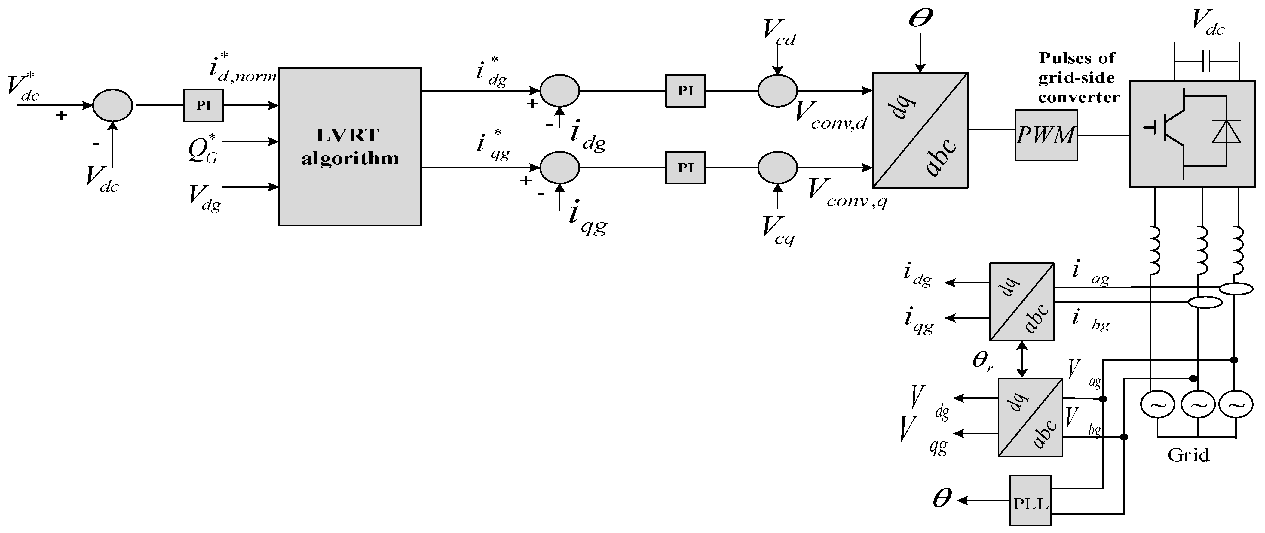
8.1. Control Strategy of Grid Side Converter

From the E-ON grid code, the LVRT will operate when there is a grid voltage dip. Suppose the grid voltage reduces below 90% of its nominal value. In that case, the system has to inject 2% reactive current for every 1% voltage dip and if it decreased below 50%, rated reactive current should be supplied to retain the system stability. Figure 10a shows the generation of d q a x i s reference currents for the grid-side converter during LVRT operation depending on E-ON German code [24].

8.2. Pitch Angle Control Strategy

As discussed in Section 2, the pitch angle has a great effect on the performance of the power coefficient C p , i.e., the output power extracted from wind turbine can be controlled through a pitch angle controller. When pitch angle increases, C p will be reduced and consequently, the mechanical power will be reduced. Figure 10b shows how the controller can regulate the pitch angle in case of grid voltage dip. When the rotor speed exceeds its reference value, or the controller detects a voltage dip, immediately, the pitch angle increases to reduce the rotor speed and hence the mechanical power.

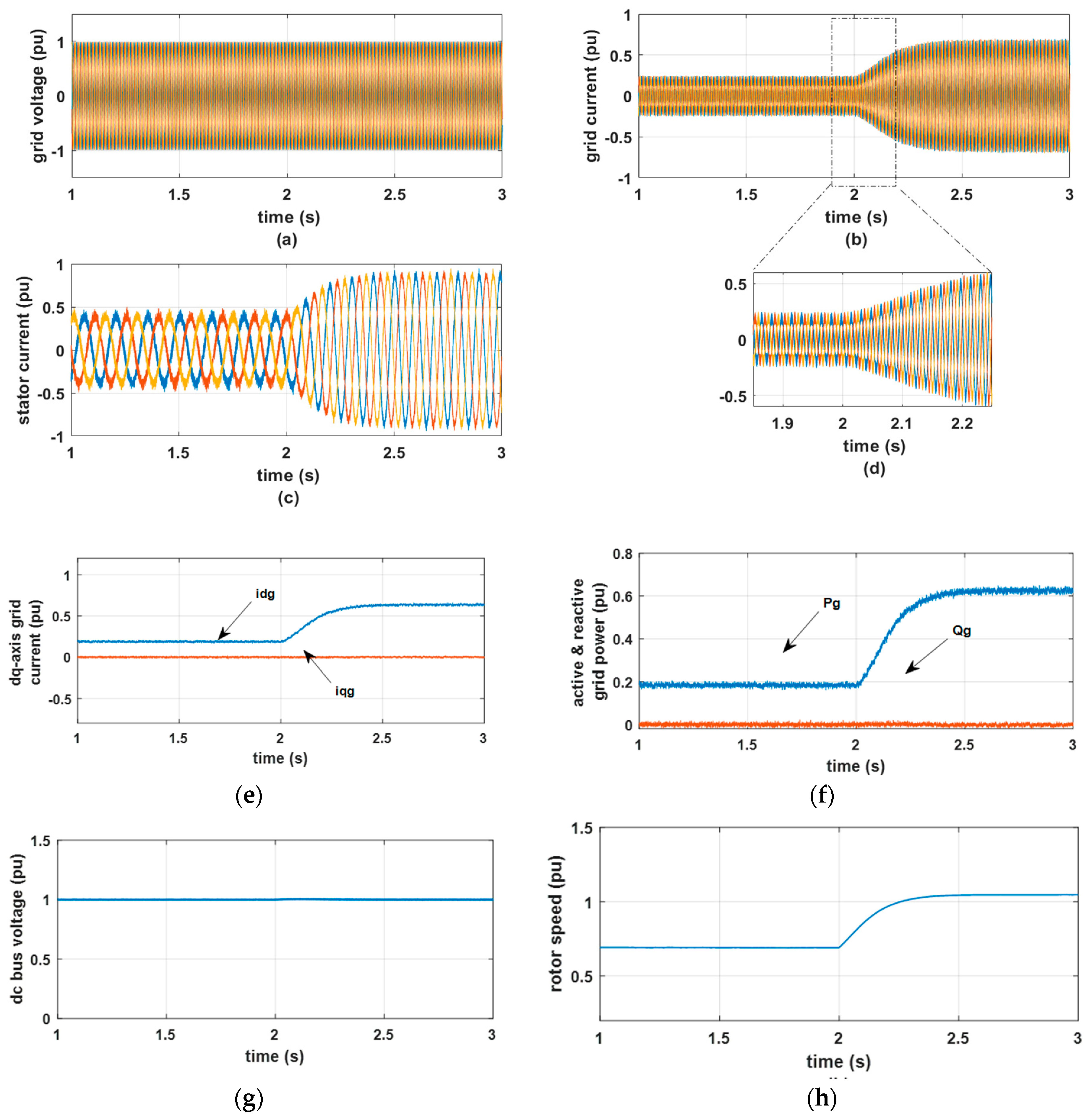
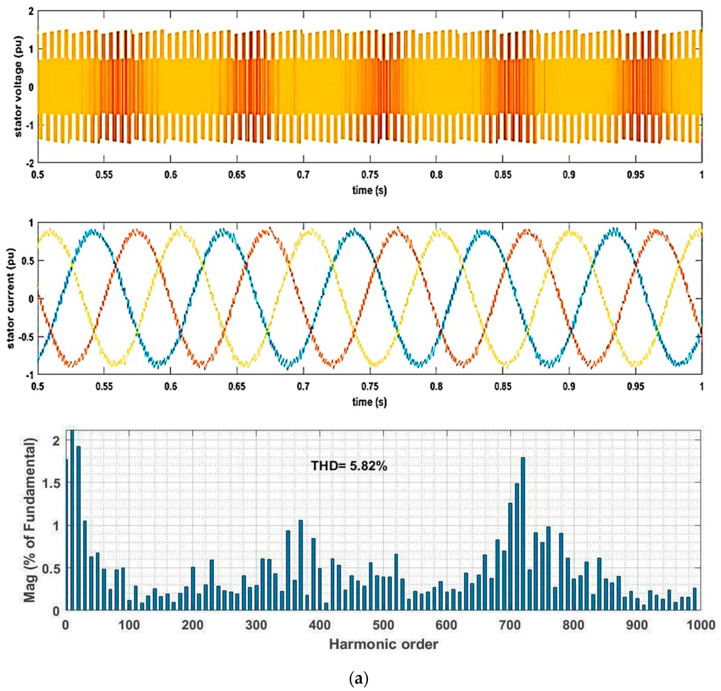
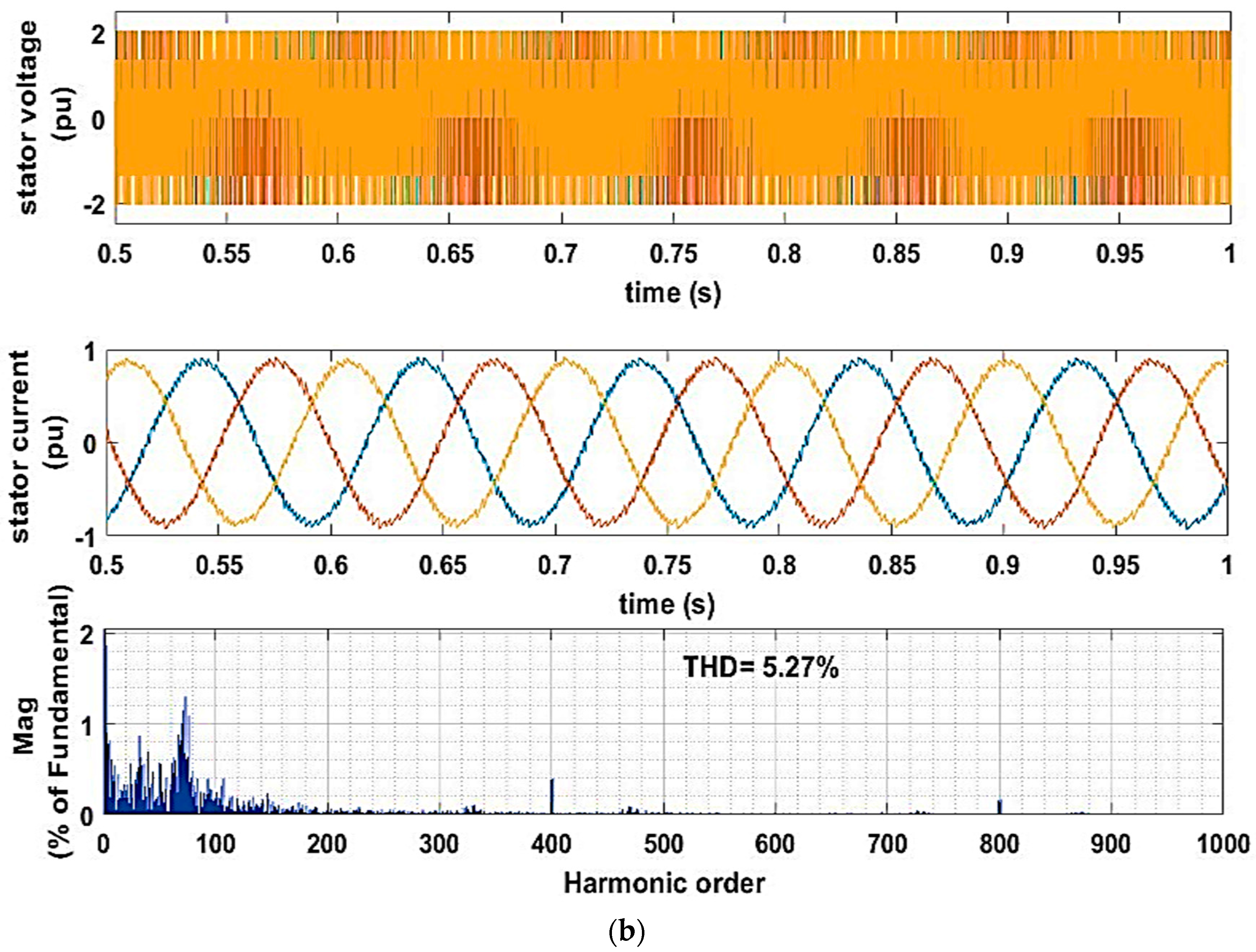
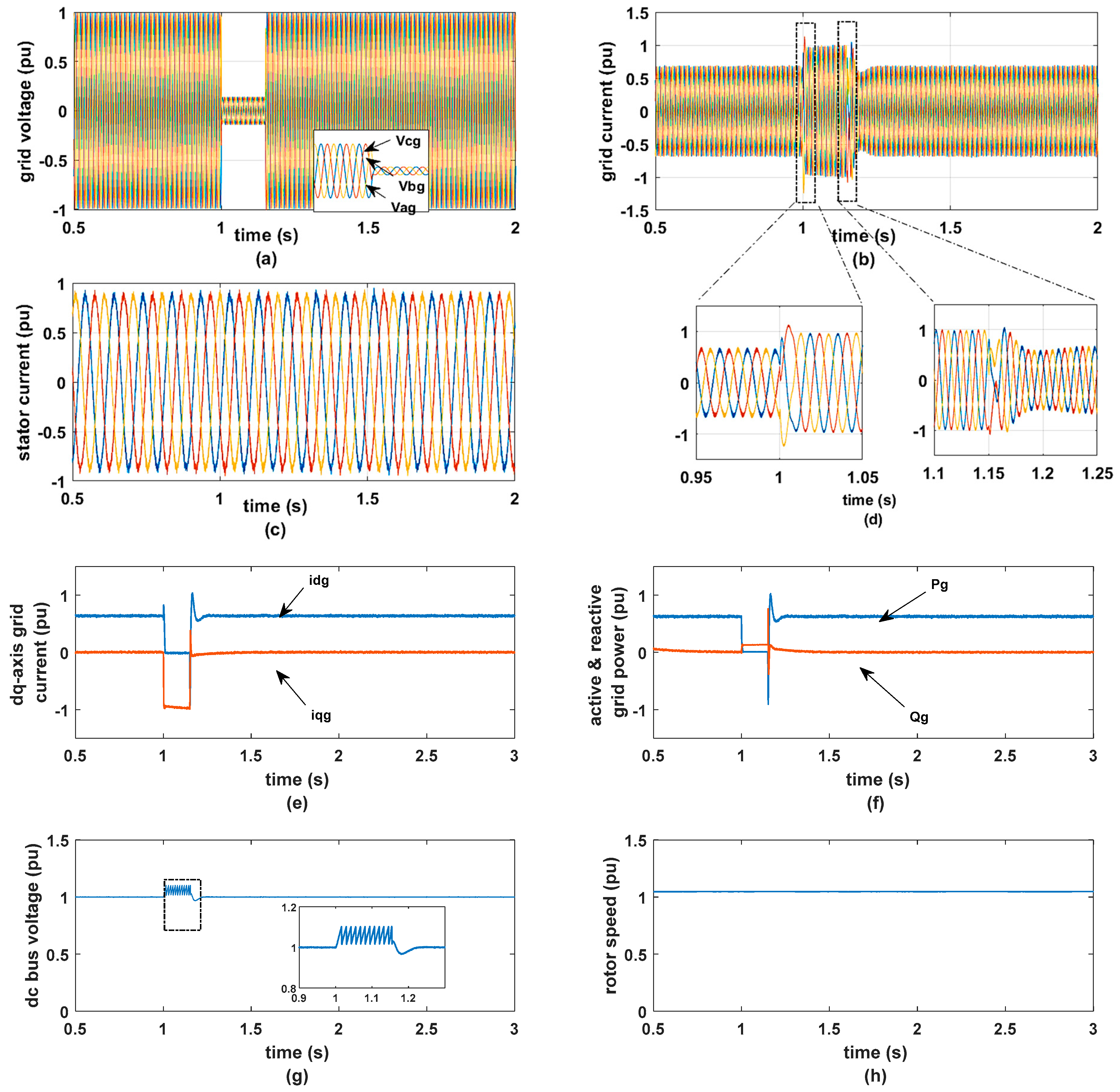
9. Simulation Results and Case Studies

In order to verify the performance of the proposed overall scheme during three-phase grid voltage dip, simulation modeling is designed via MATLAB/Simulink package. The simulation tests are carried out during transient and steady-state operation with the LVRT capability applied to the grid-side converter. Furthermore, the control performance of the conventional FCS-MPC is illustrated and compared with the control performance of the proposed MMPC. The simulation results are executed at a sampling time of T_s = 1/10,000 s while the switching frequency of the generator-side converter is noted as 4 kHz.
Case 1: For balanced grid voltage operation, the proposed MMPC algorithm performance under step increase in wind speed from 8 m/s to 12 m/s at time t = 2 s will be evaluated as shown in Figure 11.
Figure 11a–h represent the response characteristics of three-phase grid phase voltages, grid currents, stator current, zoom of grid current, dq-axis grid current, active and reactive grid power, dc bus voltage and rotor speed, respectively. All these figures are plotted in pu values for simplicity. Figure 11a,b displays the waveforms of the grid voltage and current where the grid voltage seems very smooth and have no disturbance despite the step increase in wind speed at t = 2 s. Also, the grid current tracks this variation well and it takes about 150 ms to reach its desired value, as illustrated in Figure 11d.
The PMSG stator current represented in Figure 11c also tracks the wind speed increase but it contains some harmonics which will affect the electromagnetic torque. However, under the decoupling between the generator and grid-side converters, these harmonics will not transfer to the grid. Since the system operates at unity power factor, the reactive power supplied to the grid is 0 pu. The PMSG-WECS gives only active power (Figure 11f). Moreover, this is also illustrated from the zero value of q-axis grid current. The grid has only d-axis component value, which follows the wind speed increment as presented in Figure 11e. The magnitude of DC-bus voltage in Figure 11g is maintained at its nominal value with a small overshoot and dip during the application and removal of grid fault. Figure 11h shows the PMSG rotor speed, which can mutate to wind speed variation without any oscillation.
To compare the quality for the traditional and proposed schemes in more details, the voltage and current spectra for machine side converters and total harmonic distortions (THDs) are shown in Figure 12a,b, respectively. The results show that the proposed algorithm enhances the steady-state performance than the conventional FCS-MPC. The total harmonic distortion (THD) of stator current is reduced from 5.82% to 5.27%, respectively. On the other hand, the current harmonic spectrum is concentrated over the switching frequency and its multiple such 4 kHz and 8 kHz eases the filter design. This is similar to space vector modulation PWM. In a word, these results substantiate that the MMPC with fixed switching frequency can be used in power conversion system efficiently as it reduces the converter computational effort and hence more efficiency compared to conventional FCS-MPC.
To better illustrate the comparison results, this section summarizes the aspects of both presented methods in terms of their THD, total execution time of simulation, and controller and reduction in time required as listed in Table 1. Since in the conventional FCS-MPC, only one voltage vector is applied during the whole sampling time, which results in a variation in switching frequency. The proposed MMPC applies two active and one zero voltage vectors during the sampling time based on the switching pattern in Figure 7. Thus, the computational efforts associated with the calculation of duty cycle are smaller than the conventional FCS-MPC because of the reduction in simulation and controller time.
Case 2: The effectiveness of the proposed modulated model predictive control (MMPC) with the grid-side LVRT controller is enabled ( i d g *   ( k ) = i d g , L V R T * ( k ) ,   i q g * ( k ) = i q g ,   L V R T * ( k ) ) in this case of study. Moreover, the pitch angle controller is also enabled as described in Figure 10. The control scheme is tested under transient operation with a fixed wind speed of 12 m/s and a three-phase grid voltage dip is applied from rated value to 10% of its rated at t = 1 s with a duration of 150 ms. The corresponding results of a fixed switching frequency MMPC algorithm are depicted in Figure 13.
During grid voltage dip (Figure 13a), the magnitude of grid current should increase to a higher value, but with the presence of LVRT controller, its value is limited to rated ( 1   pu ) as profiled in Figure 13b. A fast and reasonably accurate transient response with no overshoot or dip in grid current during applying and removal of grid fault as shown in Figure 13d. Also, the PMSG stator current has no response to the voltage dip, as shown in Figure 13c.
As can be seen from Figure 13b–h, the WECS could maintain the system stable under fixed wind speed so the power generation system could provide active power to the grid without any compliance. Since the system operates at unity power factor, reactive power delivered to the grid is 0 pu and the PMSG-WECS gives only active power. However, throughout the voltage dip, the active power injected into the grid decreases to zero ( i d g = 0 ) (Figure 13e), and according to power balance, this power will be stored in the dc bus capacitor. So, the PMSG should inject the system with reactive power to hold the grid voltage and prevent the dc bus voltage value from increasing above its threshold and distortion.
Thus, with the operation of LVRT, the q-axis grid current in Figure 13e is increased to a rated value (1 pu) during voltage dip and recover back to its zero value with less overshoot after fault clearance. Meanwhile, the magnitude of dc bus voltage in Figure 13g is maintained at its nominal value but with a small overshoot and dip during the application and removal of grid fault but still within its safe limits. Figure 13h highlights the PMSG rotor speed which does not mutate to the grid voltage fault, which proved that the proposed algorithm is able to operate during all possible cases without any failure to the WECS.

10. Conclusions

This paper proposed a novel MMPC of a PMSG wind energy system, which overcomes the variable switching frequency problem in the conventional FCS-MPC. Compared to FCS-MPC, the proposed MMPC gives lower THD in stator current and lower simulation time required for implementation. In addition, the operation with MMPC gives a fixed switching frequency, and lower ripple in the stator current, which reduces the ripple contents in active and reactive grid power and provides a more concentrated THD spectrum; hence, the filter design will be simple. Moreover, to compensate for the injected reactive power into the grid during faults and enhance the performance during the grid voltage dip, a coordinated LVRT algorithm, which is applied in the grid side converter, in addition to a pitch control to inject reactive power to keep the wind speed and DC-link voltage within its limits without additional expensive hardware, has been designed.
Computer simulations have been executed to evaluate the effectiveness of the proposed control strategy. The results show that the proposed MMPC has a fast transient response and smooth operation during wind speed variation and symmetrical grid fault. Moreover, it has good performances in terms of low THD in the stator currents and good robustness compared with the conventional MPC during different operation conditions.

Author Contributions

Conceptualization, A.A.G., E.G.S., A.-H.M.E. and A.A.Z.D.; methodology, A.A.G., E.G.S., A.-H.M.E. and A.A.Z.D.; software, A.A.G., E.G.S. and A.A.Z.D.; validation, A.A.G., E.G.S., H.H.A. and A.A.Z.D.; formal analysis, A.A.G., E.G.S., H.H.A. and A.A.Z.D.; investigation, E.G.S., Y.S.M., and A.A.Z.D.; resources, A.A.G., E.G.S., Y.S.M. and A.A.Z.D.; data curation, A.A.G., E.G.S., A.-H.M.E. and A.A.Z.D.; writing—original draft preparation, A.A.G., A.-H.M.E. and A.A.Z.D.; writing—review and editing, A.A.G., Y.S.M., P.S. and A.A.Z.D.; visualization, A.A.G. and A.A.Z.D.; administration, E.G.S., Y.S.M., A.-H.M.E. and A.A.Z.D.; funding acquisition, E.G.S., Y.S.M., H.H.A., P.S. and A.A.Z.D. All authors have read and agreed to the published version of the manuscript.

Funding

This research received no external funding.

Conflicts of Interest

The authors declare no conflict of interest.

Nomenclature

VariableDefinition
Pmmechanical power
ρair density
Cpthe wind turbine power coefficient
ArBlade swept area
VwWind speed
Vsd, Vsqdqaxis stator voltage of the generator
isd, isqdqaxis stator current of the generator
φsd, φsqdqaxis stator flux linkage
Ld, Lqdqaxis synchronous inductance
Teelectromagnetic torque
Rsstator resistance
Pnumber of pole pairs
φrrotor flux linkage.
ωeangular rotor speed.
Vdg, Vqgdq component of grid voltages
idg, iqgdq component of grid currents
Rg, LgFilter resistance and inductance
vdc, vqcdq component of grid-side converter voltages and is determined by the switching function S
ωgGrid voltage angular frequency.

References

  1. Mishra, R.; Saha, T.K. Performance Analysis of Model Predictive Technique Based Combined Control for PMSG-Based Distributed Generation Unit. IEEE Trans. Ind. Electron. 2020, 67, 8991–9000. [Google Scholar] [CrossRef]
  2. Zhang, Y.; Qu, C. Direct Power Control of a Pulse Width Modulation Rectifier Using Space Vector Modulation Under Unbalanced Grid Voltages. IEEE Trans. Power Electron. 2015, 30, 5892–5901. [Google Scholar] [CrossRef]
  3. Zhang, Y.; Qu, C. Table-based Direct Power Control for Three-Phase AC/DC Converters Under Unbalanced Grid Voltages. IEEE Trans. Power Electron. 2015, 30, 1. [Google Scholar] [CrossRef]
  4. Kalmbach, O.; Dirscherl, C.; Hackl, C.M. Discrete-Time DC-Link Voltage and Current Control of a Grid-Connected Inverter with LCL-Filter and Very Small DC-Link Capacitance. Energies 2020, 13, 5613. [Google Scholar] [CrossRef]
  5. Sebaaly, F.; Sharifzadeh, M.; Kanaan, H.Y.; Al-Haddad, K. Multilevel Switching Mode Operation of Finite Set Model Predictive Control for Grid-Connected Packed E-Cell (PEC) Inverter. IEEE Trans. Ind. Electron. 2020, 1. [Google Scholar] [CrossRef]
  6. Lyu, J.; Ma, B.; Yan, H.; Ji, Z.; Ding, J. A Modified Finite Control Set Model Predictive Control for 3L−NPC Grid−Connected Inverters Using Virtual Voltage Vectors. J. Electr. Eng. Technol. 2019, 15, 121–133. [Google Scholar] [CrossRef]
  7. Hu, J.; Zhu, J.; Lei, G.; Platt, G.; Dorrell, D.G. Multi-Objective Model-Predictive Control for High-Power Converters. IEEE Trans. Energy Convers. 2013, 28, 652–663. [Google Scholar]
  8. Miranda, H.; Member, S.; Cortés, P.; Yuz, J.I.; Rodríguez, J.; Member, S. Predictive Torque Control of Induction Machines Based on State-Space Models. IEEE Trans. Ind. Electron. 2009, 56, 1916–1924. [Google Scholar] [CrossRef]
  9. Antoniewicz, P.; Kazmierkowski, M.P. Virtual-Flux-Based Predictive Direct Power Control of AC/DC Converters with Online Inductance Estimation. IEEE Trans. Ind. Electron. 2008, 55, 4381–4390. [Google Scholar] [CrossRef]
  10. Geyer, T.; Papafotiou, G.; Morari, M. Model Predictive Direct Torque Control—Part I: Concept, Algorithm, and Analysis. IEEE Trans. Ind. Electron. 2009, 56, 1894–1905. [Google Scholar] [CrossRef]
  11. Papafotiou, G.; Kley, J.; Papadopoulos, K.G.; Bohren, P.; Morari, M. Model Predictive Direct Torque Control—Part II: Implementation and Experimental Evaluation. IEEE Trans. Ind. Electron. 2008, 56, 1906–1915. [Google Scholar] [CrossRef]
  12. Shehata, E. A comparative study of current control schemes for a direct-driven PMSG wind energy generation system. Electr. Power Syst. Res. 2017, 143, 197–205. [Google Scholar] [CrossRef]
  13. Abad, G.; Rodriguez, M.Á.; Poza, J. Two-Level VSC Based Predictive Direct Torque Control of the Doubly Fed Induction Machine with Reduced Torque and Flux Ripples at Low Constant Switching Frequency. IEEE Trans. Power Electron. 2008, 23, 1050–1061. [Google Scholar] [CrossRef]
  14. Vazquez, S.; Marquez, A.; Aguilera, R.; Quevedo, D.; Leon, J.I.; Franquelo, L.G. Predictive Optimal Switching Sequence Direct Power Control for Grid-Connected Power Converters. IEEE Trans. Ind. Electron. 2015, 62, 2010–2020. [Google Scholar] [CrossRef] [Green Version]
  15. Gendrin, M.; Gauthier, J.-Y.; Lin-Shi, X. A Predictive Hybrid Pulse-Width-Modulation Technique for Active-Front-End Rectifiers. IEEE Trans. Power Electron. 2017, 32, 5487–5496. [Google Scholar] [CrossRef]
  16. Zhang, Z.; Fang, H.; Gao, F.; Rodriguez, J.; Kennel, R. Multiple-Vector Model Predictive Power Control for Grid-Tied Wind Turbine System With Enhanced Steady-State Control Performance. IEEE Trans. Ind. Electron. 2017, 64, 6287–6298. [Google Scholar] [CrossRef]
  17. Tarisciotti, L.; Zanchetta, P.; Watson, A.; Clare, J.C.; Degano, M.; Bifaretti, S. Modulated Model Predictive Control for a Three-Phase Active Rectifier. IEEE Trans. Ind. Appl. 2015, 51, 1610–1620. [Google Scholar] [CrossRef]
  18. Tarisciotti, L.; Zanchetta, P.; Watson, A.; Bifaretti, S.; Clare, J.C. Modulated Model Predictive Control for a Seven-Level Cascaded H-Bridge Back-to-Back Converter. IEEE Trans. Ind. Electron. 2014, 61, 5375–5383. [Google Scholar] [CrossRef]
  19. Zhang, Y.; Wu, X.; Yuan, X.; Wang, Y.; Dai, P. Fast Model Predictive Control for Multilevel Cascaded H-Bridge STATCOM with Polynomial Computation Time. IEEE Trans. Ind. Electron. 2016, 63, 1. [Google Scholar] [CrossRef]
  20. Vijayagopal, M.; Zanchetta, P.; Empringham, L.; De Lillo, L.; Tarisciotti, L.; Wheeler, P. Control of a Direct Matrix Converter With Modulated Model-Predictive Control. IEEE Trans. Ind. Appl. 2017, 53, 2342–2349. [Google Scholar] [CrossRef]
  21. Yaramasu, V.; Wu, B.; Alepuz, S.; Kouro, S. Predictive Control for Low-Voltage Ride-Through Enhancement of Three-Level-Boost and NPC-Converter-Based PMSG Wind Turbine. IEEE Trans. Ind. Electron. 2014, 61, 6832–6843. [Google Scholar] [CrossRef]
  22. Liserre, M.; Cardenas, R.; Molinas, M.; Rodriguez, J. Overview of Multi-MW Wind Turbines and Wind Parks. IEEE Trans. Ind. Electron. 2011, 58, 1081–1095. [Google Scholar] [CrossRef]
  23. Carrillo, C.J.; Montaño, A.O.; Cidras, J.; Díaz-Dorado, E. Review of power curve modelling for wind turbines. Renew. Sustain. Energy Rev. 2013, 21, 572–581. [Google Scholar] [CrossRef]
  24. Erlich, I.; Bachmann, U. Grid code requirements concerning connection and operation of wind turbines in Germany. In Proceedings of the IEEE Power Engineering Society General Meeting, San Francisco, CA, USA, 16 June 2005; pp. 1–5. [Google Scholar]
  25. Irtija, N.; Sangoleye, F.; Tsiropoulou, E.E. Contract-Theoretic Demand Response Management in Smart Grid Systems. IEEE Access 2020, 8, 184976–184987. [Google Scholar] [CrossRef]
  26. Kim, C.; Kim, W. Coordinated Fuzzy-Based Low-Voltage Ride-Through Control for PMSG Wind Turbines and Energy Storage Systems. IEEE Access 2020, 8, 105874–105885. [Google Scholar] [CrossRef]
  27. Wang, Y.; Yu, M.; Li, Y. Improved multi-objective model predictive control of permanent magnetic synchronous generator wind power system. J. Renew. Sustain. Energy 2015, 7, 053104. [Google Scholar] [CrossRef]
  28. Calle-Prado, A.; Alepuz, S.; Bordonau, J.; Nicolas-Apruzzese, J.; Cortes, P.; Rodriguez, J. Model Predictive Current Control of Grid-Connected Neutral-Point-Clamped Converters to Meet Low-Voltage Ride-Through Requirements. IEEE Trans. Ind. Electron. 2015, 62, 1503–1514. [Google Scholar] [CrossRef] [Green Version]
  29. Guo, L.; Zhang, X.; Yang, S.; Xie, Z.; Wang, L.; Cao, R. Simplified model predictive direct torque control method without weighting factors for permanent magnet synchronous generator-based wind power system. IET Electr. Power Appl. 2017, 11, 793–804. [Google Scholar] [CrossRef]
  30. Yang, Y.; Wen, H.; Li, D. A Fast and Fixed Switching Frequency Model Predictive Control with Delay Compensation for Three-Phase Inverters. IEEE Access 2017, 5, 17904–17913. [Google Scholar] [CrossRef]
  31. Xie, W.; Wang, X.; Wang, F.; Xu, W.; Kennel, R.M.; Gerling, D.; Lorenz, R.D. Finite-Control-Set Model Predictive Torque Control with a Deadbeat Solution for PMSM Drives. IEEE Trans. Ind. Electron. 2015, 62, 5402–5410. [Google Scholar] [CrossRef]
  32. Nadour, M.; Essadki, A.; Nasser, T. Improving low-voltage ride-through capability of a multimegawatt DFIG based wind turbine under grid faults. Prot. Control. Mod. Power Syst. 2020, 5, 1–13. [Google Scholar] [CrossRef]
  33. Diab, A.A.Z.; Hassan, M.S.; Shoyama, M. Modified Adaptive Sliding Mode Control for Sensorless Direct-Drive Permanent Magnet Synchronous Generator Wind Turbines based on Fuzzy Logic Control. In Proceedings of the 2019 IEEE 4th International Future Energy Electronics Conference (IFEEC), Singapore, 25–28 November 2019; pp. 1–8. [Google Scholar]
  34. Xia, C.; Liu, T.; Shi, T.; Song, Z. A Simplified Finite-Control-Set Model-Predictive Control for Power Converters. IEEE Trans. Ind. Inform. 2014, 10, 991–1002. [Google Scholar] [CrossRef]
  35. Yaramasu, V.; Wu, B.; Chen, J. Model-Predictive Control of Grid-Tied Four-Level Diode-Clamped Inverters for High-Power Wind Energy Conversion Systems. IEEE Trans. Power Electron. 2014, 29, 2861–2873. [Google Scholar] [CrossRef]
Figure 1. Kinetic to electric energy conversion system based on direct-driven permanent magnet synchronous generator (PMSG) topology.
Electronics 10 00492 g001
Figure 2. Voltage vectors of the two-level voltage source converter.
Electronics 10 00492 g002
Figure 3. Traditional schematic diagram of finite control set-model predictive controller (FCS-MPC) system.
Electronics 10 00492 g003
Figure 4. Time sequence for the model predictive control for digital implementation.
Electronics 10 00492 g004
Figure 5. Flow chart of a conventional FCS-MPC system.
Electronics 10 00492 g005
Figure 6. Proposed taxonomy of modulated model predictive control for the MSC.
Electronics 10 00492 g006
Figure 7. Switching Pattern of voltage vectors for sector 1.
Electronics 10 00492 g007
Figure 8. Flow chart of the proposed modulated model predictive control (MMPC) system.
Electronics 10 00492 g008
Figure 9. Vector control of grid side converter.
Electronics 10 00492 g009
Figure 10. Coordinated low voltage-ride through (LVRT) algorithm: (a) Control structure of grid side converter; (b) Pitch control structure diagram.
Electronics 10 00492 g010
Figure 11. Simulation results of proposed scheme under step change of wind speed: (a) grid voltage; (b)grid current; (c) stator current; (d) Zoom of grid current; (e) dq-axis of grid current; (f) active and reactive grid power; (g) dc bus voltage; (h) rotor speed.
Electronics 10 00492 g011
Figure 12. Simulation results: Comparison of machine-side converter voltage, current spectra and total harmonic distortions (THDs) for (a) conventional FCS-MPC and (b) Proposed MMPC.
Electronics 10 00492 g012aElectronics 10 00492 g012b
Figure 13. Simulation results of proposed MMPC under three phase grid voltage dip and grid-side converter LVRT capability.
Electronics 10 00492 g013
Table 1. Summarized valuation.
FCS_MPCMMPC
THD%5.82%5.27%
Total Execution time of Simulation (s)329.67160.98
Execution time of controller (s)1.54680.7553
Reduction in time (%)51.17%
Publisher’s Note: MDPI stays neutral with regard to jurisdictional claims in published maps and institutional affiliations.

