Article

Low Voltage Ride Through Controller for a Multi-Machine Power System Using a Unified Interphase Power Controller

1
Department of Electrical Engineering, Arak Branch, Islamic Azad University, Arak 39518-79224, Iran
2
Department of Electrical Engineering, Tafresh University, Tafresh 39518-79611, Iran
3
Department of Electrical Engineering, Faculty of Engineering, Arak University, Arak 38156-8-8349, Iran
4
College of Engineering and Science, Victoria University, Melbourne 3047, Australia
*
Authors to whom correspondence should be addressed.
Electronics 2021, 10(5), 585; https://doi.org/10.3390/electronics10050585
Submission received: 11 January 2021 / Revised: 21 February 2021 / Accepted: 27 February 2021 / Published: 3 March 2021
(This article belongs to the Special Issue Voltage Stability of Microgrids in Power Systems)

Abstract

:
In recent years, grid-connected photovoltaic (PV) power generations have become the most extensively used energy resource among other types of renewable energies. Increasing integration of PV sources into the power network and their dynamic performances under fault conditions is an important issue for grid code requirements. In this paper, a PV source as a unified interphase power controller (UIPC) is used to enhance the low voltage ride through (LVRT) and transient stability of a multi-machine power system. The suggested PV-based UIPC consists of two series voltage inverters and a parallel inverter. The UIPC injects the required active and reactive power to prevent voltage drop under grid fault conditions. Accordingly, a dynamic control system is designed based on proportional-integral (PI) controllers for the PV-based UIPC to operate in both normal and fault conditions. Simulations are done using Matlab/Simulink software, and the performance of the PV-based UIPC is compared with the conventional unified power flow controller (UPFC). The results of this study indicate the more favorable impact of the PV-based UIPC on the system compared to UPFC in improving LVRT capabilities and transient stability.

1. Introduction

Distributed generations (DGs) can be defined as small-scale energy resources that are connected to distributed networks near local consumers [1]. These sources include wind turbines (WTs), small hydropower generations, gas turbines, photovoltaics (PVs), microturbines, fuel cells, geothermal energy, and so on [2]. DGs are located closer to the end-users to improve the power quality and reliability of the power system. Moreover, DGs can provide significant benefits in energy efficiency, emissions reductions, voltage profile, and component lifetimes [3]. However, with the high penetration of DGs, the stability of networks can be affected.
Today, many countries use PV systems to provide clean energy with low operating and maintenance costs [4]. PV systems are connected to the main grid using inverters to convert DC to AC power [5]. To incorporate the PVs into the main grid efficiently, low-voltage ride-through (LVRT) is suggested for PV systems [6]. According to the new grid code requirements, grid-connected PV systems should remain connected to the power system in normal circumstances [6]. LVRT capability refers to the ability to maintain and connect power sources to the grid during a fault or short circuit. Therefore, this capability can help to prevent network blackout during grid faults [7]. In addition to staying connected to the power grid, the solar system must inject the reactive power needed to recover the grid voltage. However, with the increasing use of solar systems in the power network, concerns about their stability are increasing.
With the development of power electronic equipment, the use of these devices for controlling the network, compensating reactive power, and improving transient stability has been expanded. Static compensators, active power filters, and unified power flow controllers are common examples of these devices. With this new equipment, the power grid receives the required reactive power to recover the voltage and increases the reliability under abnormal conditions. Under fault circumstances, the grid is subject to voltage drop and severe oscillations. Power electronic devices can react quickly by injecting the required active/reactive power and improving the LVRT in the power network.
Many papers have been published on LVRT controllers. In [8], using a unified power flow controller (UPFC), the LVRT is improved for a WT during voltage fluctuation. The UPFC consists of series and parallel voltage source converters. In [9], a WT using the UPFC remains connected to the network to improve the transient stability during abnormal conditions. A comprehensive review of the LVRT capability enhancement using flexible alternating current transmission system (FACTS) under fault circumstances has been performed in [10]. In [11], the authors discussed the impact of the UPFC on wind turbines and the enhancement of LVRT capability. Additionally, in [12,13], the LVRT is developed by using a static synchronous compensator (STATCOM) in wind sources with different turbines and generators. The capability of LVRT in the presence of a PV solar source without any control equipment is investigated in [14]. The proposed adaptive control algorithm can be effective in increasing the capability of LVRT capability in a network including several PVs. In [15], a solar source connected to the main grid with a boost converter and an additional transformer is used to enhanced the LVRT capability. In [16], using sequence components, the reactive power is controlled for improving the LVRT capability. In [17], the stability of a wind source using a static reactive power compensator and an adaptive fuzzy controller is ensured. In [18], the grid voltage profile is improved by the STATCOM and the hysteresis controller.
As mentioned above, the UPFC has great ability in coping with transient instabilities and compensating for active/reactive power under abnormal situations. In general, the applications of this equipment can be summarised as voltage control, power compensation control, and phase shift control, simultaneously [19]. Unified interphase power controller (UIPC) is also one of the newest FACTS devices. In such a new device, the phase shift transformers have been eliminated and replaced with power electronics [20,21]. This power controller has three voltage source converters consists of two series converters and one parallel converter. Series inverters by series voltage injection can change the phase angle of the bus voltage to which it is connected. The parallel converter can compensate the bus voltage using the capacitive link; hence, the active power required by the series inverter is provided. All of these converters are connected to a DC capacitor link [22].
Previous research has indicated that various FACTS devices have a positive influence on the LVRT in power systems. Most studies in the field of the LVRT have only focused on WT-based UPFC. However, the UIPC has the ability to deliver the active and reactive power requirements of the main grid, perform voltage compensation, and keep sources joined to the grid by increasing the transient stability level. Hence, the applicability of the UIPC for PVs needs to be investigated and important parameters for increasing LVRT capability under abnormal conditions are evaluated.
A PV-based UIPC to enhance LVRT ability for a multi-machine power system is proposed in this paper. It consists of two series voltage inverters and a parallel inverter. The suggested UIPC has the ability to inject the needed active/reactive powers to avoid voltage drop under grid fault situations. For this objective, a dynamic controller is designed for the PV-based UIPC. The suggested controller can effectively enhance the stability under grid fault circumstances.
The rest of this paper is as follows. The UIPC is presented in Section 2. The proposed controller is described in Section 3. Results and discussion are provided in Section 4. Lastly, the conclusion is given in Section 5.

2. The UIPC Operation

The integrated inter-phase power controller, or UIPC, consists of two series voltage converter and one parallel converter. Series inverters act as the inductance and reactance branches, which can change the voltage phase. These converters perform active power exchange between the source and the network at the connection point. The DC-link and parallel converter provide the required power for series converters. All three converters have a common DC link capacitor [23]. Figure 1 shows the model of the UIPC. It can be seen that the series inverters change the primary bus voltage angle (Vs) by injecting the series voltage with the specified amplitude and the angle in each branch. These voltages are named Vse1 and Vse2, according to their converters. Moreover, Vr is the connection point voltage. From Figure 1, the value of the magnitude and the voltage of the branches of the series converter is
| V s e i | = 1 2 V s sin ( φ i )
θ s e i = θ s φ i + π 2                           i = 1 , 2
where φ i , θ s , and V s are the amount of the phase change, the angle, and voltage bus, respectively.
The parallel converter controls both the UIPC bus voltage and the DC link voltage to provide the active power needed to swap between two other series converters. Note that XL and XC values of the series branches at the main system frequency (50 Hz) must be equal to each other. Figure 2 displays the circuit of the UIPC, including the equivalent series circuit and parallel converters as well as transformers.
The value of series transformer losses depends on Rse, and parallel converter losses are related to Rsh, as shown in Figure 2. Given these losses, the power exchange equation between series and parallel converters is
P s e 1 + P s e 2 + P s h = 0
where Pse1 and Pse2 are active powers of series converters and Psh is the parallel converter’s power, which can be defined as
P s e 1 = R e [ V s e 1 i u L + R s e i u L 2 ]
P s e 2 = R e [ V s e 2 i u c + R s e i u c 2 ]
P s h = R e [ V s h i s h + R s h i s h 2 ]
where losses of the transformers are modelled by Rse and voltage source converters are modelled by Rsh.
For the series converter, the current can be written as
i u = i u L + i u c = V s φ 1 V r δ j X L + V s φ 2 V r δ j X c
Considering the equality of impedances and rewriting the following equation:
i u = V s X sin ( α ) β α = φ 1 φ 2 2 β = φ 1 + φ 2 2
Therefore, the UIPC can be considered as an independent current source on the basis of the phase angle inserted from the series converters. The active and reactive power injections into the network shown in Figure 1 can be expressed as follows:
P r = 2 | V s | | V r | X sin ( α ) cos ( δ + β )
Q r = 2 | V s | | V r | X sin ( α ) sin ( δ + β )
These equations show that the amount of active and reactive power, and the apparent power produced by the UIPC depends on the difference and the sum of the angles of the series converter phases.

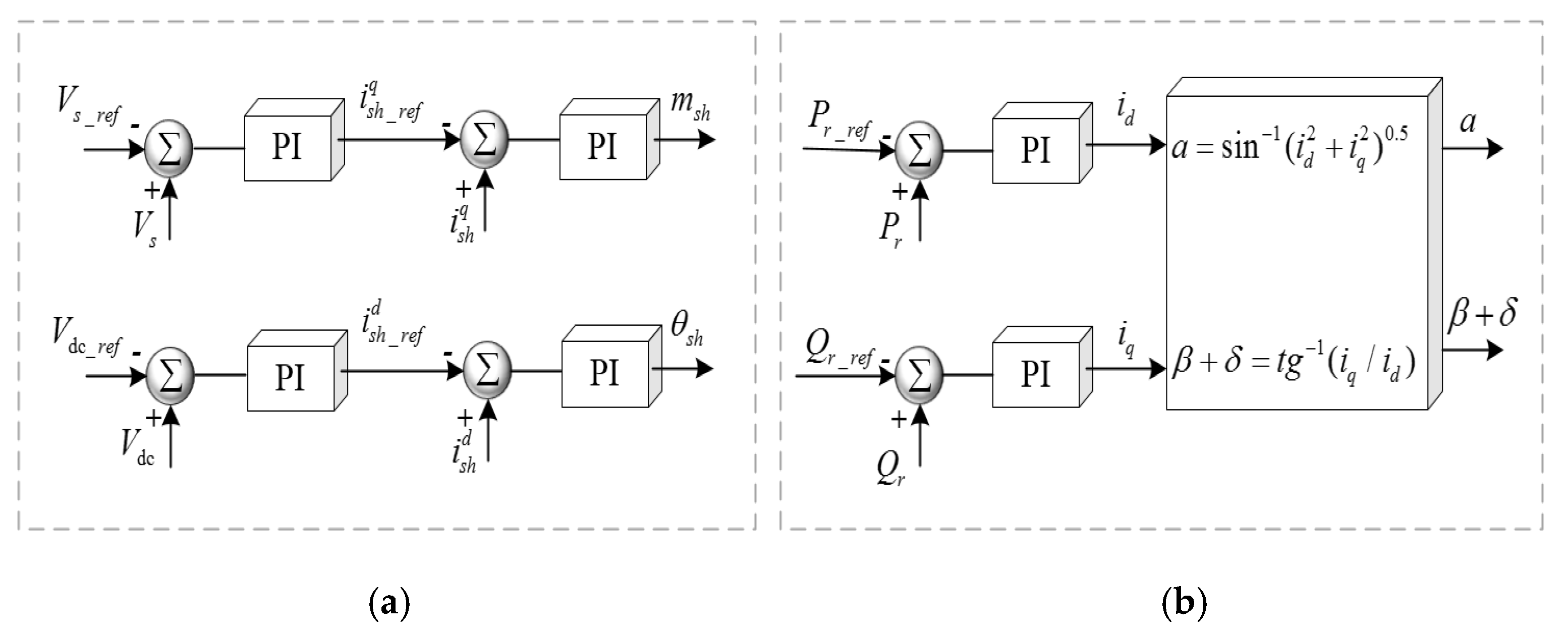
3. Proposed Controller
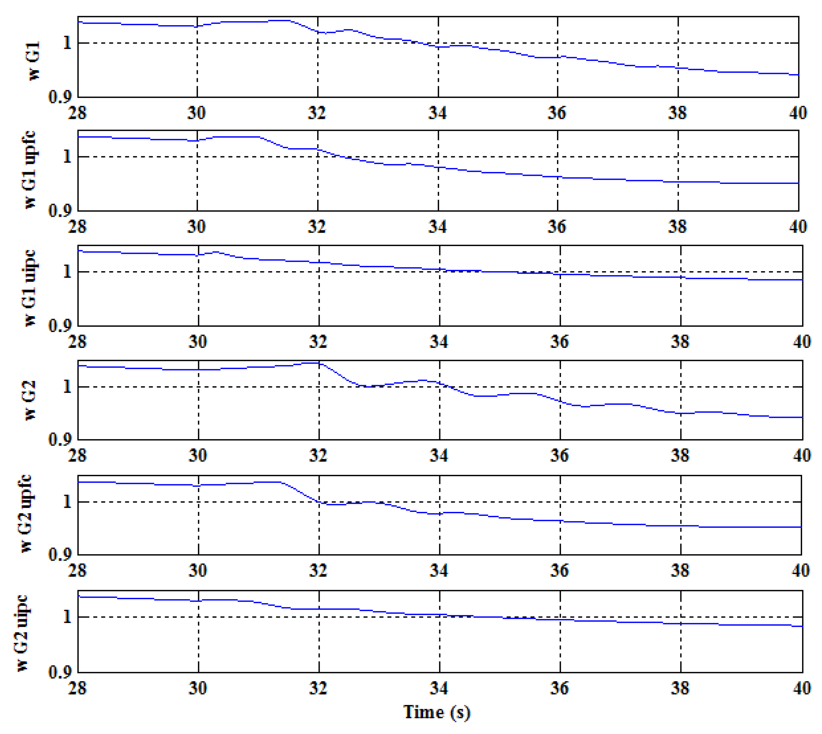
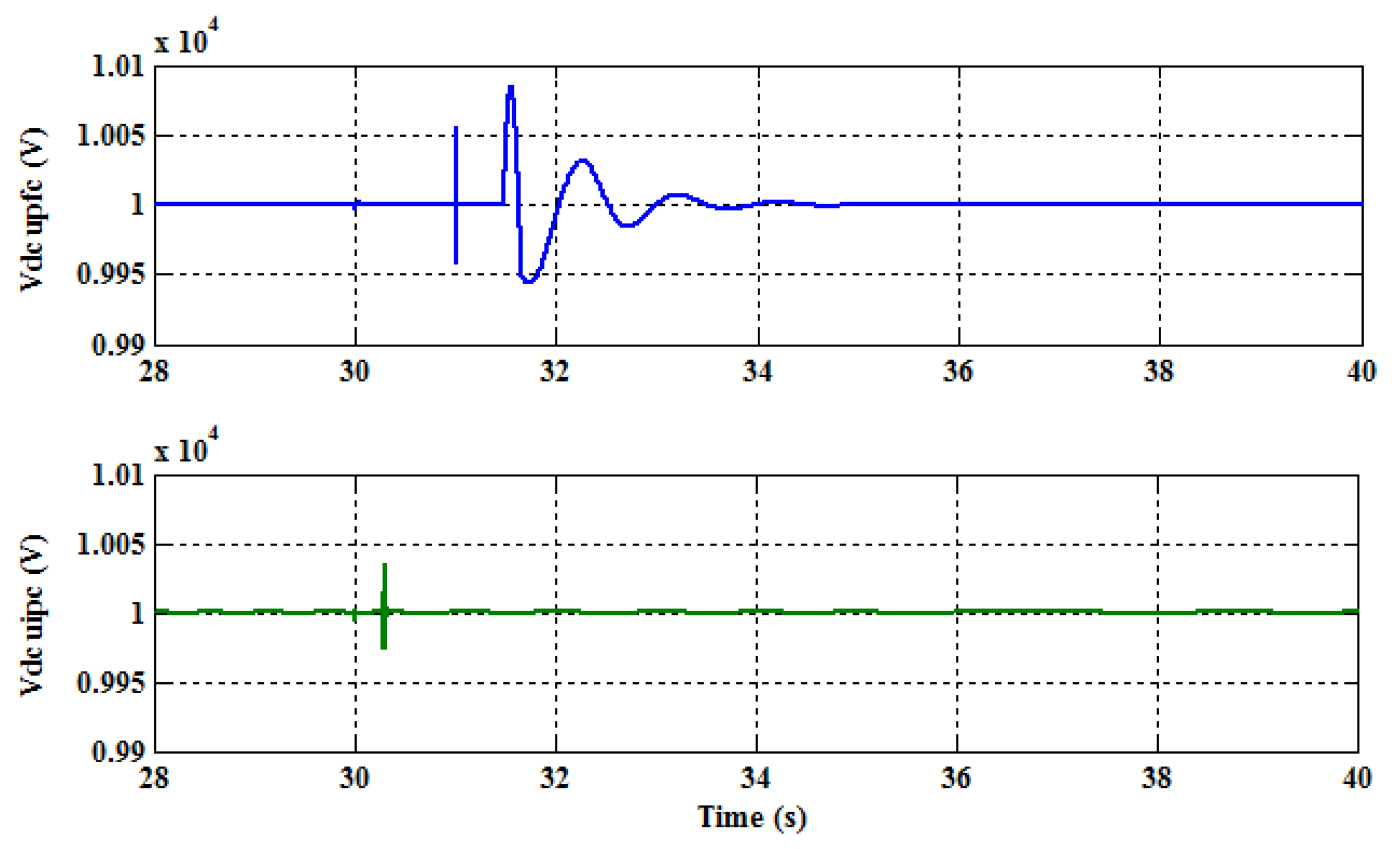
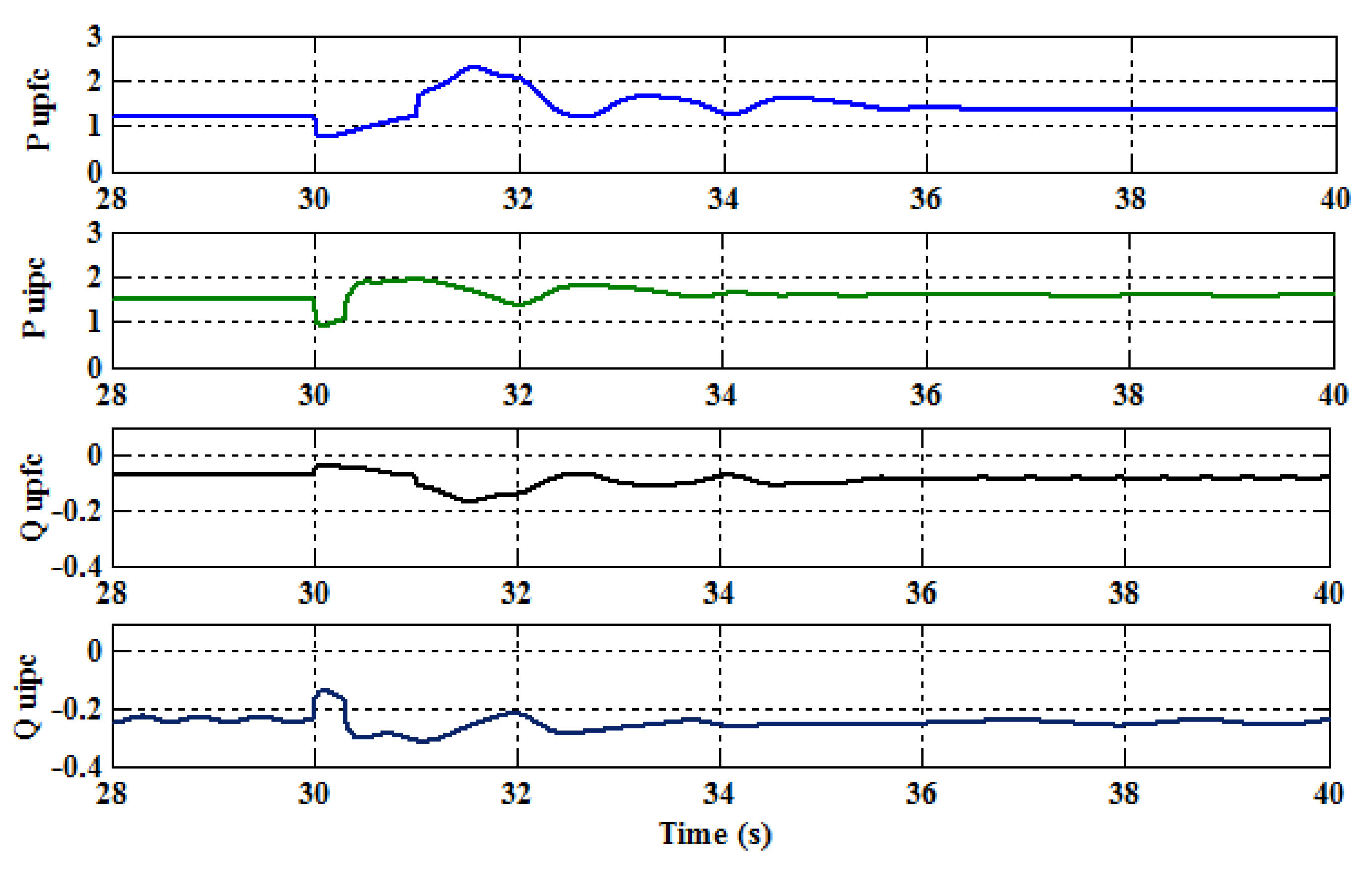
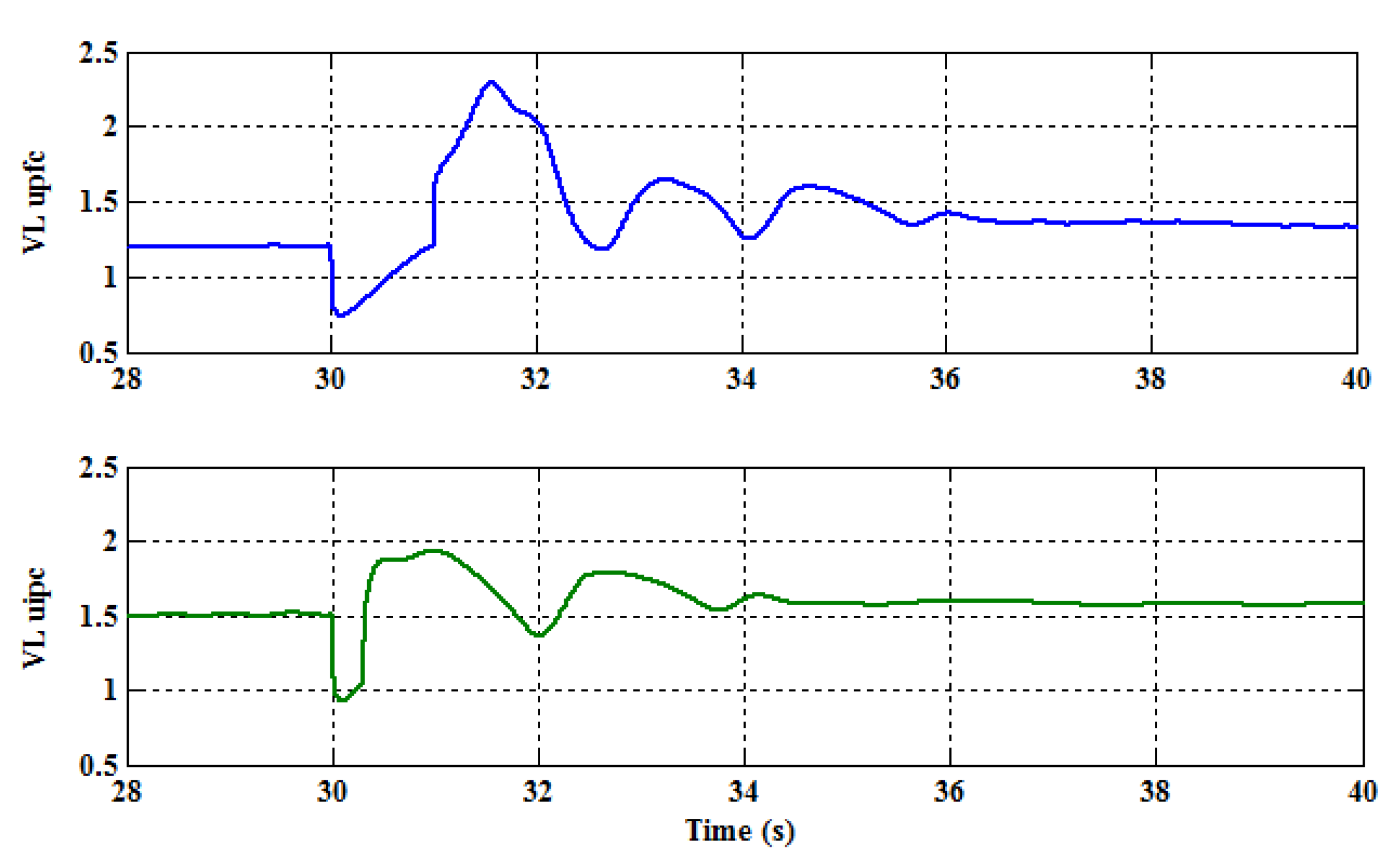
In this section, the proposed controller is described. For the derivation of the dynamic mathematical model, the model of the UIPC given in [21] is used. The ideal lossless inverter at the fundamental frequency is modeled using a dc voltage-controlled ac voltage source. The output apparent power for each UIPC branch can be written as [21]
S _ k = P k + j Q k = V _ r . I k * _
I _ k = j B e q k ( V _ s V _ s e k V _ r )               f o r   k = 1   a n d   2
The active/reactive power of the UIPC can be obtained as
P r = k = 1 , 2 P k = 2 V s V r k = 1 , 2 B e q k sin ( δ s r φ k )
Q r = k = 1 , 2 Q k = 2 V s V r k = 1 , 2 B e q k cos ( δ s r φ k )
where B e q is the equal susceptance. More details about the model is given in [21].
Considering X e q 1 = X e q 2 or B e q 1 = B e q 2 , (13) and (14) are rewritten as
P r = 2 V s V r B e q 1 sin ( α ) cos ( δ s r β )
Q r = 2 V s V r B e q 1 sin ( α ) sin ( δ s r β )
where α and β can be defined as
( α = φ 2 φ 1 2 ) a n d ( β = φ 2 + φ 1 2 )
Using (15) and (16), the following equation can be defined
P r 2 + Q r 2 = 4 V s 2 V r 2 B e q 1 2 sin 2 ( α )
Q r P r = tan ( β δ s r )
The Equations (18) and (19) indicate the dependency of the apparent output power as well as the ratio of the reactive to active power on α and β, respectively. In other words, the apparent power can be controlled using α. In addition, active and reactive powers (operating point) are regulated via β for constant apparent power. Consequently, the apparent power and one of the active or reactive power can be adjusted by tuning α and β at the same time. The phase angle of the ac voltage of the shunt converter is in charge of adjusting the exchanged active power between the shunt device and the ac network. Furthermore, the voltage amplitude of the UIPC can be regulated using the amplitude of the ac voltage of the shunt converter.
The block diagram of the proposed controller is displayed in Figure 3. The control system is divided into two parts: the series and parallel converter controllers. The parallel converter controls the amplitude of the bus voltage and DC link voltage to provide the required power by the series converter. The value of the bus voltage and the DC link can be regulated by varying the mesh modulation value (msh) and the angle of fire (θsh) at the PWM switch shown in Figure 3.
According to Figure 3b, the reference current in the d-component can be obtained by comparing the measured active power and the active power reference and then compensating through a proportional-integral (PI) controller [24]. Likewise, the reactive power reference (Qe_ref) is compared with the actual value and compensated using a PI controller to provide the q-component of the reference current for the switching. The gains of a PI controller can be obtained by the trial and error method [20,25,26].
Then, based on the equations in Figure 3, the angle values needed to switch the series converter are attained. According to Figure 3a, the amplitude of the current is determined by α and the point of reactive power operation is obtained using β . The amount of reactive power produced or the amount of output current is limited by the rated current of the series converters. The proposed controller is capable of operating under balanced grid fault conditions (three-phase to ground faults). For unbalanced grid fault conditions like single-phase to ground faults, it is necessary to compensate positive, negative, and zero sequences currents, separately.

4. Results

In this part, simulations are accomplished to confirm the efficiency of the proposed LVRT method. The test system includes a power system with four generators (G) in two symmetrical zones. The PV-based UIPC is linked to the 6th bus. The test system, including the conventional generators in two symmetrical zones and the solar system with UIPC, is shown in Figure 4. For better comparison, the performance of the suggested UIPC is compared with the UPFC. As seen, the UIPC is connected to the main grid using a transformer. To confirm the effectiveness of the offered technique, the performance of the PV-based UIPC is compared with the PV-based UPFC.
By using this scheme, the PV inverter can behave similarly to conventional synchronous generators. The parameters of UIPC are given in Table 1. It is noteworthy that these parameters are the same for both UIPC and the UPFC.
In this simulation, it is assumed that the PV system can compensate for the test system under abnormal conditions. To establish the voltage drop conditions and investigate the impact of the UIPC on improving the voltage drop, a three-phase-to-ground fault in line L3 occurs in the test system at t = 30 s. Then, breakers separate the short circuit fault quickly from the rest of the power system. Figure 5 displays the output power of Generator 1 (left side G1) in three different modes, including without compensator, with the UPFC, and with the UIPC. It is evident that after the short-circuit event, using the UIPC the oscillations in the output power can be minimised quickly. In other words, the PV-based UIPC shows a fast transient response and zero steady-state performance in comparison with the UPFC method in improving stability. According to the waveforms, the output power fluctuations are effectively reduced compared to the other two states. The UPFC can improve transient stability, but with a more significant delay than the UIPC.
Figure 6 also shows the output power of generator 2 (left side G2) in the three different states. As seen, PV-based UIPC shows enhanced stability performance in both transient and steady-state cases. It is obvious that after the fault, the fluctuations can be canceled very fast when using the UIPC. In fact, the UIPC indicates a fast transient response and zero steady-state, unlike the UPFC. The output power fluctuations are successfully mitigated compared to the other two states. The UPFC can enhance transient stability but with a more noteworthy delay than the UIPC. Figure 7 depicts the speed of generators 1 and 2 (left side G1 and G2) in three states using UIPC and UPFC and without using them. As seen, the UIPC effectively can reduce deviations and velocity fluctuations.
Figure 8 shows the DC-link voltage of the UIPC and UPFC. It can be seen that the DC-link voltage using the UIPC returns to its initial value quickly. However, the DC-link voltage returns to its original value after a few fluctuations using the UPFC. Figure 9 also displays the values of the active and reactive power outputs of the UIPC and UPFC. At the moment of the fault, the reactive power value increases to compensate for the voltage drop. It reaches its steady-state value after some fluctuations. Active power is also reduced at first with short-circuit occurrence, and after a number of swings and providing the power of the line requirement, the active power returns to its steady-state value. It can be seen that the performance of the UIPC is significantly faster than the UPFC.
Figure 10 demonstrates the voltage of these devices at the connection point. It can be seen that the UIPC reaches the steady-state very fast. Overall, UIPC shows better administration than the UPFC in improving transient stability.

5. Conclusions

Recently, PV systems have been widely used as green energy resources in distribution networks. However, the dynamic performances of PV systems under fault circumstances are a significant matter that needs to be resolved. In this study, the UIPC with a PV system to improve the transient stability and the LVRT capability is studied. The UIPC model consists of two series voltage source inverters and a parallel inverter equipped with PI controllers. The gains of a PI controller are obtained by trial and error method, and optimization of controller parameters is recommended for future works. The suggested method can improve the LVRT of the power system under abnormal conditions. For LVRT mode, the UIPC operates as a STATCOM for the main grid, capable of injecting active/reactive powers by controlling currents in the dq frame. The connecting point voltage can be compensated for by injecting reactive current to deal with LVRT needs. In addition, the use of UIPC, which is an interface between the PV system and the main grid, can increase the stability of the power system under grid fault and can also be compensated by injecting active power at the connecting point. Simulation results show that UIPC has superior performance in comparison with the UPFC for the power grid recovery and stability. It is suggested to compare the adoption of UIPC over UPFC in terms of costs and maintenance for future works.

Author Contributions

All authors participated equally to the conceptualization, methodology, implementation, writing, reviewing, and editing of the paper. All authors have read and agreed to the published version of the manuscript.

Funding

This research received no external funding.

Conflicts of Interest

The authors declare no conflict of interest.

References

  1. Moghaddam, M.J.H.; Kalam, A.; Miveh, M.R.; Naderipour, A.; Gandoman, F.H.; Ghadimi, A.A.; Abdul-Malek, Z. Improved Voltage Unbalance and Harmonics Compensation Control Strategy for an Isolated Microgrid. Energies 2018, 11, 2688. [Google Scholar] [CrossRef] [Green Version]
  2. Sa’Ed, J.A.; Amer, M.; Bodair, A.; Baransi, A.; Favuzza, S.; Zizzo, G. A Simplified Analytical Approach for Optimal Planning of Distributed Generation in Electrical Distribution Networks. Appl. Sci. 2019, 9, 5446. [Google Scholar] [CrossRef] [Green Version]
  3. Abdollahi, A.; Ghadimi, A.A.; Miveh, M.R.; Mohammadi, F.; Jurado, F. Optimal Power Flow Incorporating FACTS Devices and Stochastic Wind Power Generation Using Krill Herd Algorithm. Electronics 2020, 9, 1043. [Google Scholar] [CrossRef]
  4. Miveh, M.R.; Rahmat, M.F.; Mustafa, M.W.; Ghadimi, A.A.; Rezvani, A. An Improved Control Strategy for a Four-Leg Grid-Forming Power Converter under Unbalanced Load Conditions. Adv. Power Electron. 2016, 2016, 1–14. [Google Scholar] [CrossRef]
  5. Naderipour, A.; Abdul-Malek, Z.; Miveh, M.R.; Moghaddam, M.J.H.; Kalam, A.; Gandoman, F.H. A Harmonic Compensation Strategy in a Grid-Connected Photovoltaic System Using Zero-Sequence Control. Energies 2018, 11, 2629. [Google Scholar] [CrossRef] [Green Version]
  6. Kamil, H.S.; Said, D.M.; Mustafa, M.W.; Miveh, M.R.; Ahmad, N. Low-voltage ride-through for a three-phase four-leg photovoltaic system using SRFPI control strategy. Int. J. Electr. Comput. Eng. (IJECE) 2019, 9, 1524. [Google Scholar] [CrossRef]
  7. Hazari, R.; Mannan, M.A.; Muyeen, S.M.; Umemura, A.; Takahashi, R.; Tamura, J. Stability Augmentation of a Grid-Connected Wind Farm by Fuzzy-Logic-Controlled DFIG-Based Wind Turbines. Appl. Sci. 2017, 8, 20. [Google Scholar] [CrossRef] [Green Version]
  8. Alharbi, Y.M.; Yunus, A.M.S.; Siada, A.A. Application of UPFC to improve the LVRT capability of wind turbine generator. In Proceedings of the 2012 22nd Australasian Universities Power Engineering Conference (AUPEC), Bali, Indonesia, 26–29 September 2012; pp. 1–4. [Google Scholar]
  9. Ferdosian, M.; Abdi, H.; Bazaei, A. Improved dynamic performance of wind energy conversion system by UPFC. In Proceedings of the 2013 IEEE International Conference on Industrial Technology (ICIT), Cape Town, South Africa, 25–28 February 2013; pp. 545–550. [Google Scholar]
  10. Ibrahim, R.A.; Hamad, M.S.; Dessouky, Y.G.; Williams, B.W. A review on recent low voltage ride-through solutions for PMSG wind turbine. In Proceedings of the International Symposium on Power Electronics Power Electronics, Electrical Drives, Automation and Motion, Sorrento, Italy, 20–22 June 2012. [Google Scholar]
  11. Alharbi, Y.M.; Abu-Siada, A. Application of UPFC to improve the low-voltage-ride-through capability of DFIG. In Proceedings of the 2015 IEEE 24th International Symposium on Industrial Electronics (ISIE), Buzios, Brazil, 3–5 June 2015. [Google Scholar]
  12. Zhu, W.; Cao, R. Improved low voltage ride-through of wind farm using STATCOM and pitch control. In Proceedings of the 2009 IEEE 6th International Power Electronics and Motion Control Conference, Wuhan, China, 17–20 May 2009; pp. 2217–2221. [Google Scholar]
  13. Hossain, J.; Pota, H.; Ramos, R. Improved low-voltage-ride-through capability of fixed-speed wind turbines using decentralised control of STATCOM with energy storage system. IET Gener. Transm. Distrib. 2012, 6, 719. [Google Scholar] [CrossRef] [Green Version]
  14. Marinopoulos, A.G.; Papandrea, F.; Reza, M.; Norrga, S.; Spertino, F.; Napoli, R. Grid integration aspects of large solar PV installations: LVRT capability and reactive power/voltage support requirements. In Proceedings of the 2011 IEEE Trondheim PowerTech, Trondheim, Norway, 19–23 June 2011. [Google Scholar]
  15. Hasanien, H.M. An Adaptive Control Strategy for Low Voltage Ride Through Capability Enhancement of Grid-Connected Photovoltaic Power Plants. IEEE Trans. Power Syst. 2016, 31, 3230–3237. [Google Scholar] [CrossRef]
  16. Benz, C.H.; Franke, W.-T.; Fuchs, F.W. Low voltage ride through capability of a 5 kW grid-tied solar inverter. In Proceedings of the 14th International Power Electronics and Motion Control Conference EPE-PEMC 2010, Ohrid, Macedonia, 6–8 September 2010. [Google Scholar]
  17. Wang, L.; Truong, D.-N. Stability Enhancement of a Power System With a PMSG-Based and a DFIG-Based Offshore Wind Farm Using a SVC With an Adaptive-Network-Based Fuzzy Inference System. IEEE Trans. Ind. Electron. 2012, 60, 2799–2807. [Google Scholar] [CrossRef]
  18. Moghbel, M.; Masoum, M.A.S. D-STATCOM based on hysteresis current control to improve voltage profile of dis-tribution systems with PV solar power. In Proceedings of the 2016 Australasian Universities Power Engineering Conference (AUPEC), Brisbane, Australia, 25–28 September 2016; pp. 1–5. [Google Scholar]
  19. Rahman, M.; Ahmed, M.; Gutman, R.; O’Keefe, R.J.; Nelson, R.J.; Bian, J. UPFC application on the AEP system: Planning considerations. IEEE Trans. Power Syst. 1997, 12, 1695–1701. [Google Scholar] [CrossRef]
  20. Firouzi, M.; Gharehpetian, G.B.; Mozafari, S.B. Application of UIPC to improve power system stability and LVRT capability of SCIG-based wind farms. IET Gener. Transm. Distrib. 2017, 11, 2314–2322. [Google Scholar] [CrossRef]
  21. Pourhossein, J.; Gharehpetian, G.B.; Fathi, S.H. Unified interphase power controller (UIPC) modeling and its com-parison with IPC and UPFC. IEEE Trans. Power Deliv. 2012, 27, 1956–1963. [Google Scholar] [CrossRef]
  22. Mohamed, S.R.; Jeyanthy, P.A.; Devaraj, D.; Shwehdi, M.H.; Aldalbahi, A. DC-Link Voltage Control of a Grid-Connected Solar Photovoltaic System for Fault Ride-Through Capability Enhancement. Appl. Sci. 2019, 9, 952. [Google Scholar] [CrossRef] [Green Version]
  23. Naderipour, A.; Abdul-Malek, Z.; Ramachandaramurthy, V.K.; Kalam, A.; Miveh, M.R. Hierarchical control strategy for a three-phase 4-wire microgrid under unbalanced and nonlinear load conditions. ISA Trans. 2019, 94, 352–369. [Google Scholar] [CrossRef] [PubMed]
  24. Zin, A.A.M.; Naderipour, A.; Habibuddin, M.H.; Guerrero, J.M. Harmonic currents compensator GCI at the mi-crogrid. Electron. Lett. 2016, 52, 1714–1715. [Google Scholar]
  25. Zolfaghari, M.; Abedi, M.; Gharehpetian, G.B. Power Flow Control of Interconnected AC–DC Microgrids in Grid-Connected Hybrid Microgrids Using Modified UIPC. IEEE Trans. Smart Grid 2019, 10, 6298–6307. [Google Scholar] [CrossRef]
  26. Firouzi, M.; Gharehpetian, G.B.; Salami, Y. Active and reactive power control of wind farm for enhancement transient stability of multi-machine power system using UIPC. IET Renew. Power Gener. 2017, 11, 1246–1252. [Google Scholar] [CrossRef]
Figure 1. The actual model of unified interphase power controller (UIPC) equipment.
Electronics 10 00585 g001
Figure 2. Equivalent circuit of UIPC.
Electronics 10 00585 g002
Figure 3. Block diagram of the proposed control system: (a) series converter control and (b) parallel converter control.
Electronics 10 00585 g003
Figure 4. Photovoltaic (PV)-based UIPC connected to the main grid.
Electronics 10 00585 g004
Figure 5. The output power of Generator 1 (left side G1) in three different modes, including without compensator (P G1), with unified power flow controller (UPFC) (P G1upfc), and with UIPC (PG1uipc).
Electronics 10 00585 g005
Figure 6. The output power of Generator 2 (left side G2) in three different modes: without any compensator, with UPFC, and with UIPC.
Electronics 10 00585 g006
Figure 7. Speed of generators 1 and 2 (left side G1 and G2) in three states without a compensator, using UIPC and UPFC.
Electronics 10 00585 g007
Figure 8. DC-link voltage for the UPFC and UIPC.
Electronics 10 00585 g008
Figure 9. Active and reactive power outputs of the UIPC and UPFC.
Electronics 10 00585 g009
Figure 10. The output voltage of the UPFC and UIPC at the connection point.
Electronics 10 00585 g010
Table 1. Parameters of UIPC.
ParametersValues
Rated SEC150 MVA
Rated SEC250 MVA
Rated SHC50 MVA
XL = XC78.89 Ω
L280 mH
C38.18 uF
DC-link voltage (VDC)5 kV
Publisher’s Note: MDPI stays neutral with regard to jurisdictional claims in published maps and institutional affiliations.

