Abstract
Unmanned aircraft, which are more commonly known as drones, are nowadays extensively used in an ever increasing set of applications. In a wider system, the aircraft are usually associated to additional elements such as ground-based controllers. Furthermore, when these components form a network of elements that can communicate, the system is said to form an Unmanned Aircraft System (UAS). This system is particularly effective when the aircraft within are organized into swarms with sets of objectives to accomplish. The extensive use of swarms into UASs is more and more exploited nowadays due to the decreasing cost of those aircraft. In the present work we are interested in a particular application of UASs, namely their deployment in disaster scenarios for communications services provision to targets on the ground. These ground targets, however, are not part of the UASs and should not be confused with ground-based controllers. The present work does not only focus on coverage for ground targets but also on a guaranteed minimum number of covers for each target, which is called the redundancy requirement. The research work also ensures that the deployed UAS forms a unique connected component so that a steady stream of communication is kept with the targets to cover. Research work similar to the present perform the initial deployment of their aircraft in a different manner, either randomly, based on a predetermined grid formation, or using other elaborated methods. This work proposes a new solution based on the use of clustering algorithms, combined to a design of the problem formulated as a set cover optimization model. The clustering phase is used to discretize the search space and ease the optimization phase by locating regions of interest, and then a further procedure is applied, only when needed, to reconnect scattered connected components and guarantee connectivity in the networks. This way of doing it has achieved a deployment of UASs with maximum coverage for all targets, a guaranteed minimum number of covers for each of them, and results in a competitive computation time. The latter also allowed for more scalability by extending the tests to very large input instances.
1. Introduction
It is always a complicated task to know how serious a disaster scenario can be. Nobody can confidently assert that the consequences of an aftermath can be controlled. It can even be more dramatic when there are people trapped in isolated crowds that are unable to use their communication devices, often because of loss of network coverage. It has indeed been reported that in disaster scenarios people are usually unable to use their mobile and/or smart-phones in a normal way [1,2]. In order then to prevent such hardship, a lot of effort has been used to provide efficient responses, and among those we find the use of Unmanned Aircraft Systems (UASs), suggested for relief operations in disaster scenarios [3,4] and effective to monitor difficult-to-access regions [5].
Originally, UASs with a single aircraft were introduced. However, due to significant technological advancements, particularly improvements in wireless communication, the swarm in the UASs became larger, and with it the number of missions to accomplish. With these advancements the UASs were, for example, able to act as access points for users making calls or connecting to the Internet [6,7]. One such application can for instance be found in the deployment of UASs for provision of reliable communication services to fixed targets on the ground [8].
In this work, we consider these kinds of applications where the goal is to deploy a UAS for communication services provisions to targets on the ground.
Although the term aircraft (or even Unmanned Aerial Vehicles (UAVs)) is more widely used by the public, official institutions such as the International Civil Aviation Organization and the Single European Sky Air-Traffic-Management Research Joint, have adopted Unmanned Aircraft Systems as the terminology that better emphasizes the importance of elements other than just the aircraft (ground control stations, data links, etc.). For instance, in our context, ground-based control stations could be added to the UAS, and would regularly assemble new updates about the positions of moving ground targets in order to decide on new deployments. However, given that the transmission range of aircraft is usually high with respect to the expected mobility of ground nodes, and also that in a disaster scenario context most people are trapped, the expected mobility would be moderate and thus the changes between updates.
Considering then the deployment of UASs for communication provision to ground targets in a disaster scenario, a minimum guarantee of reliable services is required. With then the aim of establishing minimum conditions for safe communication, the present work mainly focuses on two requirements: the coverage and redundancy requirements [9]. These two requirements have for respective concern: (1) to maximize the number of targets covered, and (2) to strengthen the ability of a ground node to stay covered in the event of aircraft failure. Furthermore, to a lesser extent, the research work also considers a sharing of work between the aircraft in case of congestion.
This redundancy requirement is also often referred to as the k-coverage problem [10], where k is the minimum number of covers required for each target. Furthermore, although the coverage requirement is considered as the most significant objective in this work, the redundancy is also profitable for two already aforementioned reasons: (1) a ground node covered more than once can stay covered in the event of covers failure, (2) a heavily charged aircraft can be relieved of some ground targets and transfer them to other aircraft. We then focus on providing methods for the two components at the same time: coverage and redundancy requirement.
This work is contributing to the research by proposing a new strategy for dealing with the deployment of UASs, consisting in: finding good and limited potential locations for aircraft placements, and filter them by solving a set cover problem combining both the coverage and the redundancy requirement into a single mono-objective model. The approach consists of two principal procedures: (1) apply clustering methods to generate locations into areas of interest. These locations are obtained by iteratively considering shorter ranges for aircraft, which adds diversity in the search space. (2) run the optimization phase to further filter the generated locations and keep the ones that satisfy the best the coverage and redundancy requirements. Finally, when both the coverage and redundancy constraints are satisfied, an additional routine is applied, only when necessary, that builds a single connected component in order to satisfy the connectivity of the resulting network.
With this approach, we were able to achieve good results in a competitive computation time: full coverage for all the targets, a guaranteed k-coverage, and the connectivity of the overall UAS. Plus, since the solution provided results very fast for instances of moderate size, it allowed us to expand the tests and scale the solution to much larger search space, both on the number of targets to cover and on the size of the map.
This report is structured as follows: related work is presented in Section 2 and a formal description of the task under consideration in Section 3. We are presenting in Section 4 our proposed approach: the selected formulation for the problem (Section 4.1) and details on the approach we adopted to generate the required SCP instances (Section 4.2). In Section 5 we provide details on how the redundancy requirement is incorporated in the model and describe how we managed to guarantee the connectivity of our network. We present in Section 6 the results of our experiments, plus additional tests for the scalability of the solution, and we finally conclude in Section 7.
2. Related Work
There is already a considerable amount of material available on the subject of deployment of UASs. It is an issue that has been thoroughly studied, and many solutions are already available for several of its components, coverage in particular.
For instance, several approaches similar to ours are using clustering algorithms to find appropriate positions for the UASs. In [7], the authors use clustering methods to deploy their UAS in a context where aircraft are used to complement macrocell infrastructures in regions with high traffic of user equipment. In their work, the authors use the K-means clustering algorithm to deploy a predefined number of aircraft, which is function of the number of targets to offload from the macrocells and the maximum number of targets that can be simultaneously offloaded by a single aircraft. They subsequently seek macrocells with high numbers of user equipment connected to them, while also computing the distance of these macrocells to the aircraft so that they can identify macrocells to offload first. In our work we also consider this capacity constraint for the aircraft, even though it is not explicitly mentioned. For us, when an aircraft is overloaded, we provide a solution to ease congestion by constraining targets to be covered with more than one aircraft. Thus making possible the sharing of burden in the UASs.
In a more recent work [11], the authors propose a multiobjective optimization model which seeks to minimize the number of deployed aircraft while minimizing the data rate dissatisfaction of relays. In this research work, the idea relevant to our purpose is to take advantage of the position of ground targets to reduce the search space. The authors use a convex hull envelope to reduce their search space and position their UASs into a mesh formation on which they can apply genetic modifications using the NSGA-II elitist multiobjective evolutionary algorithm. The use of the mesh network allows them to easily apply genetic modifications while keeping the overall UAS connected. This work is also similar to our set cover model in the fact that their model has elements common with our model of reference: one of their two objectives is to minimize the number of used aircraft while constraining at least one of them to cover each ground node. The model, however, has its own specificity and cannot be presented as just a multiobjective problem integrating a set cover model.
Similarly to the two aforementioned works [7,11], our approach also takes advantage of the positions of ground targets to infer suitable positions for aircraft to be placed. However, unlike these works, our work does not impose any predefined number of partitions nor enforce a predefined network formation. We rather use different methods mainly consisting in generating as many varied potential partitions as it is possible to find. We then give the UASs the possibility to have a nondeterministic formation. Our approach can then be seen as more dynamic.
Each of the preceding choices have both advantages and drawbacks, particularly when used for our specific problem. In [7], applying a dynamic search, that is the ratio of the number of user equipment (ground targets) needed to offload, to the maximum capacity of aircraft, can avoid many hardships. However, if there is more user equipment found in a given partition than an aircraft can handle, there can never be overlaps of coverage. That means that only one aircraft can be deployed at the exact coordinates of one centroid (Voronoi cell), unless several aircraft are deployed at these precise coordinates. In other words, only the amount of user equipment that a single aircraft can handle can be offloaded. For our part, we approach the matter differently and use a dynamic assignment of the number of aircrafts to deploy. We were able to find a way of generating several different potential locations for the UAS, even in the coordinates already generated for some aircraft.
For [11], even though deploying a mesh network in a reduced search space can be beneficial on many points, in some cases this can cost a lot and not provide any improvement. That is the case when the targets to cover are largely spread over the map, or when there are large gaps between distinct connected components. For example, in our test instance of Section 6 that can be visualized in Figure 1, we have 125 ground targets in red, mainly aggregated into four regions but largely spread over the map. If we had used the approach of enclosing the search space into the convex hull of the target nodes, and placed the potential placement points for the UAS in a grid layout where the distance between two placements is equal to the range of the aircraft, just only one placement point on the bottom right of the map (the red point) would have been discarded. Moreover, depending on the distance used to fix neighbor aircraft in the UAS mesh network, a lot of them would be needed just for connecting the gaps between the separated connected components, without covering any ground target at all. The convex hull search space reduction would have returned roughly the entire map.
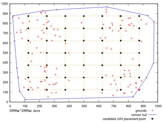
Figure 1.
Candidates for aircraft placement as a mesh network within a convex hull.
Another interesting work is [12]. In this research work, the authors have developed a biobjective linear model where one of the objective is to minimize the deployment cost of the UASs, and the other is to find the best altitude for an aircraft that provides the best coverage. Their model is also constrained to maintain full coverage of the targets on the ground, as well as a connectivity constraint in the resulting UASs. In their experiments they consider a 3D environment search space where the aircraft can have different altitudes but need to stay in range for coverage and communication requirements. However, as in [11], the UAS is placed in a grid formation. Furthermore, in spite of guaranteeing the connectivity of the UASs, these are still deployed in a rather rigid manner that can be very expensive when the different connected components are far apart.
The problem we are dealing with is also to be found in other domains related to our subject. It is indeed the case that different communities are actively endeavoring to tackle the coverage problem and alike issues. For instance, the coverage problem is widely studied in research for wireless sensor networks. A large collection of genetic ([10,13]) and evolutionary solutions ([9,14]) have been suggested to solve the coverage problem and other similar objectives. Likewise, exact approaches have also been used jointly with heuristics to solve for example the network lifetime maximization problem ([15,16]). This latter objective is not to provide simultaneous coverage but to maximize the total amount of time during which the targets are covered. This kind of problem is usually solved using a strategy of deploying more sensors than actually needed so that they can be able to switch between active and dormant sensors [16].
Nonetheless, it seemed to us that many of these work would have been even more productive if they had started with better initial solutions. In most of these works the initial deployment is performed either randomly ([9,16]), using predetermined formation ([11]) or through the use of more sophisticated methods, such as the Monte-Carlo method ([13]). So, further to the concern of finding good deployments to start with, we were able to provide an approach that finds good initial positions based on the coordinates of the ground nodes to cover. We suppose then that, prior to the deployment, a scan of the search space has been accomplished to collect the positions of all the ground nodes.
For instance, in [17], the authors use a particle swarm optimization based approach to fast-track positions of target nodes with potential convergence into areas with high amount of targets. Furthermore, in the same spirit, there are other solutions that could help detect or approximate the positions of isolated ground targets without being able to provide the full services that a UAS could. Using satellite images or low cellphone signal detection with a sweep of the search space can give a close representation of the positions of the targets.
The other criterion related to practical considerations for UASs deployments in disaster scenarios is to take into account the cost of physical equipment. High precision material for problems such as the one at hand are still far from being very accessible. Military and scientific grade navigation systems are the only ones able to provide very good accuracy and small error rate even for non static objects tracking. However, they often come at a very high cost. More common and cheaper equipment on the other hand are less reliable and usually subject to disruptions. So, depending on the acceptable degree of accuracy required by the deployment, that difference should always be remembered.
As a conclusion, when we compared our research work to those seen previously, we could see from experiments that we have yet to improve our approach in tackling the connectivity issue. Indeed, our goal being to ensure first full coverage and redundancy for the target nodes, the connectivity issue is tackled only afterwards and only if necessary. The method used for that matter can be perceived as too straightforward as it seeks to connect the spread components by iteratively linking the two closest. Still, even with this simple method we were able to obtain fast results of fully connected UASs with full coverage for a substantial number of targets scattered over large maps.
3. Problem Description
Presented briefly, the problem we intend to solve consists in deploying UASs to monitor (or cover) as many ground targets nodes as possible. We also assume that the size of the search space (the map) is known, and the positions of the ground targets too (given by their coordinates). For the objective of our model, we need to cover all the ground nodes with a minimum number of aircraft. Furthermore, in order to strengthen the covers we also enforce as a constraint a redundancy feature (or k-coverage), that ensures each target is covered with at least k covers.
More formally, we have a set U of k potential locations available for the deployment of the UAS: with their respective coordinates . The ground nodes (or targets), to cover are given by a set T of size n: with fixed coordinates within the limits of a two-dimensional map. Every potential location of U can only be established within the boundaries of the map, and we also assume a transmission range for every such location , that allows an aircraft assigned to that location to cover ground nodes within that transmission range, or communicate with other aircraft in other locations. We then have an undirected graph , where , and E is the set of edges expressing whether there is a connection target-aircraft or aircraft-aircraft. An edge is a pair , indicating whether a ground node is covered by an aircraft situated at a given location, or if two aircraft assigned to two different locations can share information. Such edges exist either if (1) and j is in the covering range of i (j is covered by i); or (2) and both aircraft are in the transmission range of each other. To this end, we use the disk model, or Boolean disk coverage model ([13,18]), to assess whether either of the conditions above hold:
The considered distance is the usual Euclidean distance: , where are the respective coordinates of i and j. And for symmetry breaking purposes, if a ground node v is covered by an aircraft located at u then and ; and if two aircraft at location and are in the range of each other, then for , and .
Regarding the redundancy requirement, a ground node i is said to have a redundancy, or accessibility of p, if it can be covered simultaneously from p different aircraft. One way of computing the total redundancy of the deployment of the UAS is, for each target to sum the number of deployed aircraft that cover it. In [9] for instance, the authors encoded such measurement, that they optimized under a multiobjective model. The optimization expression can be translated in our notation with (3), whereas if the expression is only needed for measurement purposes, (4) can be used. In our model, is used as a decision variable stating whether a given aircraft is activated at the potential location u in the deployment.
In the present work, we chose a different approach than using the redundancy as a specific objective in a multiobjective problem. We propose a simple mono-objective SCP approach consisting in minimizing the number of deployed aircraft in the UAS while guaranteeing a minimum redundancy for the targets. Furthermore, although (3) is not explicitly included in the model, it is used in Section 6 as a means of measurement to evaluate our experiments.
As stated, our work focuses mainly on the coverage and redundancy matters. Even though the connectivity constraint is also enforced on networks, this step is performed after obtaining a deployment that satisfies the two aforementioned constraints. It is only then that we apply an additional routine to connect all the spread connected components. We are fully aware of how tricky the connectivity requirement can be. Although the connectivity constraint is an essential component of all the research work presented in Section 2, it is always at the expense of either the deployment cost (number of used aircraft), the quality of the coverage, or even the time cost: whereas the stiff mesh deployment of [11,12] causes a deployment of more than needed aircraft to keep the connectivity, the clustering approach of [7] does not allow for a full coverage in some cases. Furthermore, compared to these works, the proposed solution favors input instances with much larger targets to cover and provides results in much faster time. Hence, the straightforward method used for connectivity does not undermine the results of the solution.
In the next section we present the set cover integer model used for solving our problem, before we can detail how the instances for the Set Cover Problem were obtained. We made that choice to first give an in depth presentation of the approach selected for solving our problem, and then show how we managed to obtain the input data.
4. Proposed Approach
4.1. Set Covering Optimization Problem Formulation
Given the problem described in Section 3, the proposed set covering problem formulation is stated in (5)–(7). It is an Integer Programming problem (IP problem) whose objective function (5) is to activate for deployment the minimum number of aircraft (or covers), to complete their mission. aircraft locations are activated for deployment through the use of a set of integer decision variables stated in constraint (7) where: a given aircraft is activated for deployment at location when , otherwise, no aircraft is deployed at this position (). The redundancy restriction of covering targets with a given minimum number p of aircraft is stated in constraint (6).
This model is not always easy to solve. It is a hard problem in itself (NP-Complete [19]), which is added to the fact that IP problems are hard at some point compared to their linear counterparts [20]. IP problems are usually solved based on the results of their linear relaxations, which consists in loosening some or all of the integer constraints by allowing them to be continuous. One simple such strategy is to relax the integer variables, solve the linear problem, and translate back the linear problem to its original IP version by fixing the continuous values to their closest integers. However, it is an oversimplification at the expense of qualitative results. For the most part, and in spite of ensuing longer running time, IP/MIP solvers usually provide better strategies for solving the problems or detect earlier unfeasible instances.
Still, due to the combinatorial explosion of IP problems, precautions are to be taken so as to not make the problem harder from the start. Some procedures used in IP solvers, such as enumeration approaches, branch-and-bound, or cutting-plane techniques, are indeed very sensitive to growth in size. Enumeration methods are time-consuming when building and searching through large branching trees needed to check the possible solutions, and cutting planes, in some instances, generate substantial cuts to find integer optimums, leading to lengthy operations. Fortunately, other techniques are used to ease the process, among which is the use of heuristics.
For our purpose, rather than using heuristics to solve IP problems efficiently, we chose to use them to generate good input values for the IP/MIP solver. Our solution produces input data of limited size that are used to solve the problem with an IP/MIP solver. We were cautious not to produce too many locations too big for the solver. Our approach generates limited positions around areas of interest, by learning from the positions of the targets. In this paper, due to the fact that we are using a set cover approach, we often refer to the generated locations as covers.
Instead of randomly generating these covers then, we propose a solution that produces limited numbers of them that at the very least will never be empty, as might happen in random procedures. Surely, there would be no real advantage of using the SCP model if we were not able to provide smaller and good input instances for the solver. The risk with random generations is that not only a lot of generated covers are usually not valuable enough, but it can also be hard to find the appropriate number of covers to generate and find an easy instance for the solver. In other words, there are too few covers—the result might miss valuable choices, potentially leading to unfeasible solutions—, and too many covers —and the instances could lead to an intractable problem. In the former case, it is even possible to have randomly generated covers with no targets covered at all. With our approach we propose a method that always find covers with targets within and that are never empty.
In the next section we describe with more details how these discrete instances are found.
4.2. Generating SCP Instances
As stated before, in its raw form, only the coordinates of the ground nodes are known; thus, there is no cover available yet (instances) for the SCP solver. In order to transform raw data into SCP instances, we performed a preprocessing using clustering methods: to group targets into clusters of diverse sizes. These clusters (covers), are circular areas of radius the range of the aircraft. For simplification, at this point we suppose that all the aircraft in the UAS have the same range. Furthermore, given that in the beginning the number of needed covers is not known, we use a clustering algorithm known as the single pass algorithm [21] in order to find it. As a result, we also obtain the coordinates of the representatives or centroids of the clusters. These representatives are points in the map such that the distance of a ground node in a given cluster to its representative (the aircraft location in our case) is strictly less to a given threshold (the range of the aircraft). This representative is also the closest compared to other representatives: if a target belongs to a cluster , then, from (1): , and there is no other cluster such that .
The single pass algorithm is given in Algorithm 1. In short, the algorithm scans once over the whole set of ground nodes and for each ground node seeks the closest representative in range and assigns it to that cluster. If no representative is close enough, then a new cluster is created with the current target as its representative.
Algorithm 1 begins by considering the first read ground node as the first representative and as the only node in the first cluster. It then repeats the updating step until all ground nodes are organized into clusters. The updating rule for the representatives consists in computing mean vectors of the points within each cluster. In the algorithm, represents the closest cluster to the current target ; is the centroid of the closest cluster; and is every target in cluster .
At the end, we have K clusters, with , where N is the number of targets to collect into clusters. It is guaranteed that if we assign K aircraft to the coordinates of the representatives of each cluster, then all the ground nodes will be covered. The complexity of Algorithm 1 is polynomial (, or ), with the worst case occurring when there are as many clusters as there are ground nodes (K = N). This happens when the distance between the two closest ground nodes is higher than the highest threshold. It is useful to note that even though this situation is in reality less likely to occur, the algorithm provides for that scenario the optimal maximum coverage, as there is no better solution than to deploy as many aircraft as there are ground nodes if the objective is a maximum coverage of the ground nodes. It is also important to point out that except for this worst case scenario, the algorithm can never deploy all the aircraft at the exact position of the targets.
Some comments should be made about the results of the algorithm. First, although using the single pass clustering method has advantages such as generating discrete instances, it also has flaws. Indeed, the formed clusters and their representatives are dependent of the order in which the nodes are read [22]. Nonetheless, the resulting number of cluster is a good indicator to start with. Plus, now that the needed number of clusters is approximated, the algorithm can be supplemented with better clustering methods, such as the k-means algorithm, to improve the values of the representatives.
| Algorithm 1 Single pass algorithm |
|
Second, and related to the first remark, the single pass algorithm and k-means are hard-clustering algorithms, that assign each ground node to only one single cluster. That somehow makes them not appropriate for our purpose. Indeed, because of the redundancy requirement, we value more targets that are present in diverse covers. We could use a soft-clustering algorithm that would allow ground nodes to belong to different clusters at the time. However, it turns out that the time complexity of a classic soft-clustering algorithm cannot get any better than using a routine that simply checks whether a ground node is in the range of a given aircraft: using a k-means type algorithm to improve the position of representatives and combine it to a subroutine that pairs each ground node to accessible representatives, the overall complexity sums up to (), with T the number of iterations needed to reach the tolerable error range (the stopping criterion). While on the other hand, the complexity of a soft-clustering algorithm, like fuzzy c-means, is [23], without taking into account the dimension of the problem.
Finally, and similarly to the second point, since there are other objectives that need to be optimized, building stiff covers is not really valuable for the diversity of the solution. With the tight results obtained with hard clustering algorithms, we might end up using some results and miss other interesting ones, as for instance with the arguments we presented concerning the hard kind of clustering used in [7]. As mentioned in Section 2, this causes the deployment of aircraft to not be able to really adapt to the topology of the targets to cover. Moreover, if as in our case, the objective is to find the best covers between large given choices, then it is precisely better to have a large and diverse choice than just a predefined number of partitions. Therefore, we believe that adding further alternatives to the solutions could be more profitable. For that purpose then, we adopted a strategy consisting in shortening the range of the aircraft while running the single pass algorithm several times, so that we have smaller and smaller clusters and can generate more different centroids and more positions inside the centroids. In addition to having all ground nodes covered, the approach also produces more positions than if only the true range is used. Furthermore, these locations are produced only around areas of interest, i.e., in areas where at least one ground node is present.
This method works as follows: start by running the single pass algorithm with the true range of the aircraft as the threshold for each clusters, then keep applying the single pass algorithm with shortened threshold until a stopping criterion is met. We chose to shorten the threshold by dividing the true range of the aircraft by 2, 3, 4, and so on, until the stopping criterion is met. Furthermore, for each iteration, we kept the representatives found previously, except for the duplicates. The intuition behind is to gather the targets into smaller and smaller groups, starting with clusters of radius the initial range of the aircraft.
As for the stopping criterion, lowering too much the range could lead to unproductive clusters where, for example, all the clusters cover only a single ground node. Thus, tuning the right value for the reduction is also of great importance. Diversity is important but having a dense search space with not so much differences between the covers fades the allure of the solutions. Furthermore, finding too many representatives could prolong the search when few good ones could have been enough. In order then to find a good limited reductions, we applied the elbow method usually used to approximate the number of clusters needed for the partitions. The method finds the number P of clusters such that adding another cluster does not significantly decrease the Within-cluster Sum of Squares (WSS), the sum of squares of the standard deviation, or intracluster variations: , where d is an element in cluster , and the mean vector of that cluster. After that number P, the state of the clusters is more or less stable and there is not much benefit in increasing P.
In our approach the elbow method is used to find the value where the minimum WSS significantly changes for series of reductions: first with the true range, and then with the latter divided by 2, 3, 4, and so on until the elbow criteria is reached. This can be seen in Figure 2, where the WSS is plotted for series of reduction of range. The line chart presents a stiff bend after the range is reduced to a quarter of its true value. As a consequence, for that specific instance we fixed the value of the reduction to a quarter of the true range. It is the reduction we used to produce the covers illustrated in Figure 3. That avoids having too many clusters and fix a number of clusters such that the arrangements of targets within the clusters is stable.
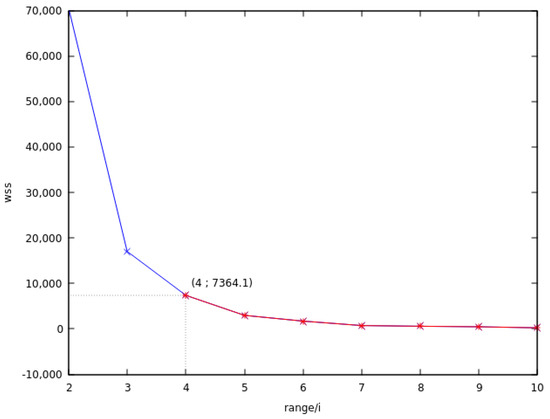
Figure 2.
Minimum within-cluster sum of square measurements for different reductions.
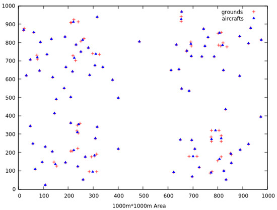
Figure 3.
Set of aircraft placements obtained using reduced ranges.
Still, the elbow method should not be the only stopping criteria. Indeed, if for instance the input instance consists of only isolated ground nodes and our approach is used, we will always obtain as many clusters as there are ground nodes, given that the WSS will always be 0 since there will be no intracluster variation. As a consequence, we will never find any elbow criterion. Thus, the iterations should stop when the elbow criterion is reached or when the WSS is close to 0.
Figure 4 illustrates the clusters when the single pass algorithm is used with just the true ranges, while Figure 3 shows them when the reducing range method is applied.
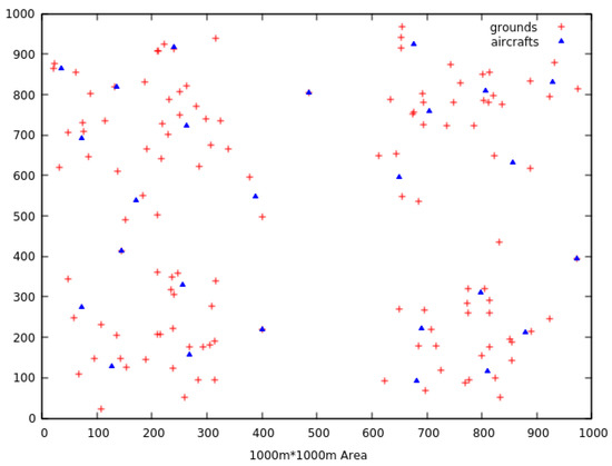
Figure 4.
Set of aircraft placements obtained using true ranges.
It is important to notice that not all resulting locations are generated at the exact locations of target nodes.
5. Redundancy and Connectivity
The other benefit of using the reduction strategy is that if many clusters are generated, then the ground nodes are more likely to be covered by several centroids (the aircraft placements) than they would if the usual range is used. That situation is very helpful for the other issue we are working on: the redundancy of coverage. It helps enhancing the robustness of the network by preventing aircraft failures to cause ground nodes to lose coverage and can also help prevent congestion. The idea is to simultaneously cover each ground node with more than one aircraft. By doing so, the coverage stays valid even when some aircraft fail, and since the targets have many covers they can switch to other aircraft when they start overcrowding.
Redundancy is simply achieved by fixing a minimum needed k-coverage in constraint (6) of the SCP model. Indeed, even if a coverage of 1 is usually required, it is still possible to restrict more the constraint. However, small minimum values of k-coverage should be favored if inexpensive solutions are preferred. Otherwise, it gets less and less likely to satisfy the constraint as p increases. Occasionally, the clustering step is not enough to satisfy constraint (6) when the generated positions offer less than p covers for a given target. This mostly happens for isolated target nodes. In these specific cases, one can replicate the coordinates of aircraft that cover distant target.
Once coverage and redundancy are guaranteed, the remaining hardship is to provide connectivity in the UAS as the resulting networks might indeed not always be organized as a single connected component. The issue with this sparse deployment is that even though the targets are fully covered, a proper flow of communication in the UAS, as well as communication services for the targets, is still not possible. These breaches in communication break the integrity of the network, hence making the connectivity an essential element of the problem.
In the previous Section 4, we introduced the difficulty of handling the connectivity requirement. We have seen that grid networks can guarantee the sustainability of connectivity in the UASs, however, most of the time at the expense of the number of aircraft to use. The other option not using rigid deployments could be to add in the linear programming model a connectivity constraint of type flow network, as in [12]. This would however further complicate the problem by expanding the search space to the whole map, as there are no aircraft positions completely dedicated to connecting the different components. Furthermore, if we try to reduce the search space to the convex hull of the targets as in [11], this would not help much, as the search space reduction would be marginal.
At this stage we came up with a simple alternative that does not take into account the size of the map and provides a connected solution in a limited number of operations. It is a quite simple solution consisting in a pairwise comparison of validated aircraft placements contained in different connected components. It takes as input the aircraft locations returned by the IP solver satisfying the coverage and redundancy constraints. Then the solution works by (1) iteratively finding the two closest location that belong to different connected components, (2) adding a new aircraft placement at the center, and then (3) repeating the operation until only one connected component remains. It is important to note that after a new aircraft placement is added by (2), it is still possible that the two connected components are still disconnected when their two closest locations are too far away from each other. In that case the new position can even create an additional connected component with only this new location inside. However, after all the iterations are performed, at the end only a unique connected component remains.
In spite of its simplicity, the deployment in our approach is still better than the two approaches of Section 2, by its flexibility, given that it does not require any rigid grid deployment, and the complexity of its search of a unique connected component is still polynomial: , L being the number of iterations required to link all the different connected components.
Still, the approach does not provide good results for what is called the k-connectivity or k-vertex-connectivity measure of a graph. The k-connectivity of a graph is the minimum number of vertices needed to break the connectivity of the graph. That means if a graph is of k-connectivity k, then removing at most any k-1 vertices does not disconnect the graph but removing specific k vertices will. The k-connectivity should not be confused with the k-coverage seen previously. In [9], the k-connectivity is used as a specific objective to optimize, and referred to as the fault-tolerance. In this research work the k-connectivity is usually of 1 but tends to slightly improve due to its presence in the objective functions, which is inciting for the model that leans toward more rewarding solutions.
With our solution the resultant k-connectivity will usually be of 1, unless it is coincidental. When it is missing from the start, the connectivity is indeed built by iteratively finding the position that links the two closest components, and for each iteration, there can only be one such position. But as we will see next, the k-connectivity of our result can be improved.
The stages of building a unique connected component are reported in Figure 5, where we used the same instance as in Figure 4, and the redundancy value is set to 2. Figure 5a shows the deployment returned by the MIP solver. The results satisfy the coverage and redundancy constraints but not the connectivity. The ground targets in red are linked to the aircraft in green, with links depicted with blue lines. In Figure 5b, only the links between aircraft within admissible range are displayed. 15 connected components are counted, with some aircraft covering only one target. There are four such aircraft (with 2 duplicates of 2 aircraft) that form two isolated components covering the 2 lone targets. Due to the redundancy requirement, the two isolated targets have two aircraft covering each of them and that are deployed at their exact coordinates. This cannot however be seen with the 2D visualization.
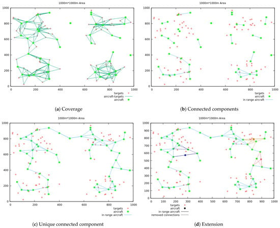
Figure 5.
Stages of building a connected component.
Using then the iterative unions of the two closest connected components, we obtain a first feasible solution displayed in Figure 5c. We can next improve the k-connectivity by extending this first result and restrict some connectivity aircraft positions in the following solutions. For example, in Figure 5d we have three new connectivity positions generated by forbidding some links from the previous solutions. The new solutions are displayed with solid lines of the same color as their forbidden counterparts (with dashed lines). The operation can be repeated as many times as wanted until there is no pair of positions to forbid left.
To sum up, the approach proposed in the present paper works in three main stages:
- perform a first phase of generating good positions of interest for the aircraft around ground targets,
- use an MIP solver to filter out as many positions generated in step 1 as possible and keep the ones that cover more efficiently the targets with the minimum number of aircraft, while at the same time satisfy the redundancy requirement,
- connect (only if necessary) the different components into a single one.
If the K positions produced in the first clustering phase are not sufficient for the redundancy constraint, an additional duplication phase is used to complete them, and only then the second (optimization) phase can be applied. After the third and last phase, the unique connected component is obtained by iteratively connecting the two closest components. Furthermore, diversity in the connectivity can be added by extending the initial results with a tabu search like process, which is beneficial for the k-connectivity feature.
6. Experimental Results and Scalability of the Solution
In order to evaluate the efficiency of the proposed approach and demonstrate its validity for the problem at hand, we assembled different sets of test instances to run with the application. In this section we present the results of our experiments and study the extent of scalability of the solution by analyzing its behavior on instances of very large sizes.
The instances to use had to present features of disaster scenarios in a two-dimensional map. We generated instances with nonuniform distribution of the targets, with some form of aggregations into clusters in order to model the natural inclination of people to gather into groups. This configuration also turns out to be more challenging for the network coverage problem than random and densely deployed networks [24,25].
We should also highlight the importance of considering legal regulations when actual physical implementations of UASs deployments are to take place. They do not always apply the same way under different rules. For instance, under European rule the Commission implementing regulation (EU) 2019/947 of 24 May 2019 established set of categories under which UASs are to operate. They were made in order to evaluate the degree of risk involved by the UASs and decide the requirements they have to abide to. The present work is however still on its preliminary stage and does not consider any particular legal framework. It is only proposing a proof-of-concept research work that has yet to be physically implemented.
The experiments were then organized into two series of tests. The first, with instances of lighter number of targets to cover, was used to follow the different processes the solution goes through and for which it was easier to interpret the results. For the second series, with instances of much higher amount of number of targets, and larger size of maps, we have used it to further assess the cost of the solution in terms of execution time and identify the configurations that challenge the most the application as a whole, as well as its specific steps.
Early on, we had to choose which MIP solver we would use for our SCP model. In Section 4.1, we gave some context for the reasons of preferring a pure MIP solver over linear relaxations. We also mentioned the fact that instances with many targets can sometimes be harder for the solver and can even be intractable. There are many free or commercials Mixed-Integer Programming (MIP) available, and occasionally, free solvers can outperform commercial ones [26]. Free solvers are usually limited by the size of the instances they can take on, but even in that case they can handle problems of relatively large size. For our part, we chose the free MIP solver GLPK (GNU Linear Programming Kit (accessed on 29 December 2020)) that is easy to handle, can take up big problems without much difficulties (up to a thousand integer variables [27]) and is among the most effective free MIP solvers available [26]. Its C/C++ API gives users lots of procedures they can use to configure, change, and set different control parameters, and it can also accept many standards input formats. However, of course, compared to commercial solvers, it is outperformed in terms of available algorithms and performance, but on instances of decent size we have witnessed that it performs very well and is fast. For the anecdote, we also tried the naive solution outlined in Section 4.1, consisting in relaxing the integer variables of the SCP model and activate for example the positions whose values returned by the linear solver are greater or equal to 0.5. As expected, the quality of the results between the two methods was largely in favor of the pure MIP solver.
6.1. Simulation Set-Up
All the experiments were accomplished with the solution coded in C++, with the GLPK API used to solve the MIP programs, and the igraph C library (accessed on 29 December 2020) used to find the different connected components of the generated graphs. The solution was running on a computer under Debian 10, with an Intel Core i3-3220 @ 3.30GHz processor and a RAM of 8 Gigabytes.
As aforementioned, we have implemented two series of experiments: the first a collection of five instances, used to study the inherent validity of the application and follow the different steps of the approach. With these instances it was easier to control the results graphically, simpler to identify and manipulate the different steps the solution goes through, and was also possible to compare the results with other benchmarks. Furthermore, in order to assess the reliability of our solution, we assumed necessary to examine how it responded on more challenging instances and how its run-time cost behaved on gradually increasing numbers of targets to cover. That is why we implemented the second series of experiments.
The simulations parameters of the first and second series of experiments are summarized in Table 1. In the first series there are five instances with different distribution of targets contained within a map of area dimension 1000 × 1000 m. In addition, for all these instances the aircraft are considered to have a range of 125 m. The instances consist of 50, 75, 100, and 125 targets to cover, plus an additional instance of 50 targets with all targets isolated, used to constrain the solution on the specific task of reconnecting the different connected components. The distributions of targets in the different instances are presented from Figure 6a–e, where the positions of the ground nodes are marked in red. The instances with 50, 75, 100, 125 ground nodes are respectively represented from Figure 6a–d, while Figure 6e presents the distribution of the special case where all the ground nodes are isolated.

Table 1.
Simulation parameters of the two series of experiments.
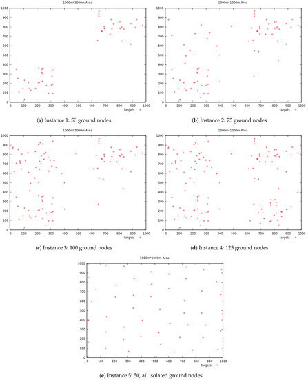
Figure 6.
Distribution of the different test instances.
The second series of experiments on the other hand consist of six sets of 20 instances each. For the twenty instances in each set, the number of targets to cover is increasingly getting larger: from 50 targets, and growing every time by 50 more targets, until an instance of 1000 targets is reached (). The difference between the instances in the sets resides in the dispersion of the targets which is growing with each consecutive set. This second series was made to challenge the application and detect the configurations that are harder to handle, but also, since the goal is to get as close as possible to realistic scenarios, to use instances with numerous and separate targets, as it is usually the case in real-life.
In that regard then, the generated 20 input instances in each sets were organized such that they were growing larger in number but also such that the dispersion in each set was higher compared to its previous. In order to demonstrate that the dispersion was indeed expanding, we calculated the standard deviation of the targets in each of the 20 instances in the sets, and then calculated the quartiles of these standard deviations needed to draw the box-plots in Figure 7 (see Table 2). The dispersion is indeed expanding with each successive sets, the interquartile range is relatively the same for all the sets, and there are no outlets.
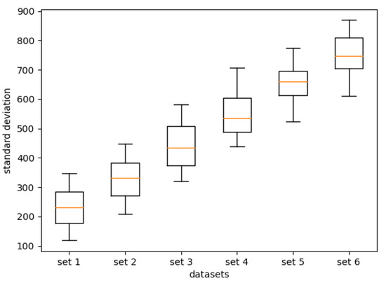
Figure 7.
For each test set used for scalability analysis (set 1 to set 6): the box-plots of the standard deviation of the targets in each of the 20 input data (50 targets to 1000 targets).

Table 2.
Simulation parameters of second series of experiments.
6.2. Simulation Results
6.2.1. Results of First Series of Experiments
For the five different instances in the first series of experiments, and for the values of and of (6), the application provided solutions satisfying all the constraints: coverage, redundancy, and connectivity; in less than 1 decisecond. Table 3 presents the results of the application on the five input instances, executed with different values of p. The table provides the number of locations generated on each of the three stages of the application: (1) the clustering phase that finds regions of interest around the target nodes; (2) the optimization phase that filters the locations generated in the first phase and keep those that minimize the objective function (5), subject to the constraints; (3) when necessary, complete coverage and redundancy with the connectivity constraint. The number of aircraft in the first phase does not change for different values of p since in that phase p is not relevant. Table 3 also provides the value of redundancy for the overall network. In instance 5 with , we can notice that there are twice the number of aircraft deployed than there are number of targets. This is due to the fact that there are numerous gaps between the generated UAS, which hinders it to form a unique connected component. This shows that the positions of target nodes influence the cost of the final network.

Table 3.
Results for the input instances with 2 values of required minimum redundancy parameter p.
The final solutions for the five different instances, all with can be seen in Figure 8. For each figure, the red crosses represent the ground nodes, the green squares represent the aircraft generated by the MIP solver (2nd phase), and the orange squares those used for connections. The edges represent the connections aircraft-aircraft. For Figure 8e, the targets cannot be seen as they are hidden by the aircraft covering them, and only 50 aircraft used for coverage can be seen in green rather than 100, since aircraft are overlapping, due to the redundancy of 2, and the fact that targets are isolated.
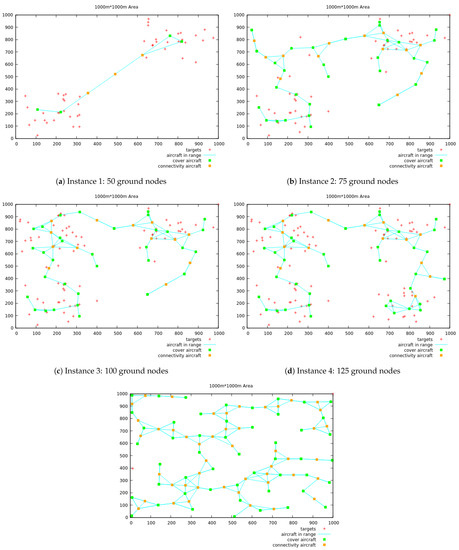
Figure 8.
Graphical results for the 5 input tests instances, with .
As expected, the number of aircraft deployed increase with the number of targets but more importantly with their dispersion. This can be seen with instance 5 (Figure 6e) where there are very few targets but many gaps between them. For this special case it would be more profitable to place the aircraft at the middle of two isolated ground nodes, but it is hard to identify those structures beforehand.
The other interesting case, more plausible as UASs deployments are usually needed in places with targets gathered into relatively compact groups, is Figure 8d where several targets are spread on the map. When , the first phase generates 105 potential locations, then in the second phase, the GLPK MIP solver filters these positions to less than a half of them (42 aircraft to deploy).
In addition, although it is not apparent in the 2D figures, aircraft can overlap due to the duplication required for the redundancy on isolated ground nodes. For instance, in Figure 8d, two aircraft are overlapping at coordinates about (500,800), and cover an isolated target at that exact position. These isolated ground nodes, together with aircraft used for connectivity, are with not much surprise the ones that cost the most. So, the redundancy requirement should be fixed with caution if one does not want the number of activated aircraft to steadily grow. Nonetheless, into areas with great concentration of ground nodes there is a strong potential of redundancy, as in the instance in Figure 8d where sometimes ground nodes are covered with up to five active aircraft.
6.2.2. Scalability (Results of Second Series of Experiments)
As presented in Section 6.1, with regard to the second series of experiments, the objective was to analyze the overall run-time growth of the approach on large and growing sets of instances. It was also to evaluate the execution time of the particular three main steps of the approach so that we can detect the ones that are more challenged depending on the number of targets to cover and their distribution. The results for the six datasets are given in Figure 9 and Figure 10, where on the left we have the consecutive run-times on a specific set and on the right the distribution of the most challenging instance for that particular set (the peak). The time costs are represented in green (•) for the first phase, cyan (•) for the MIP problem, yellow (•) for the connectivity, and fuchsia (•) for the overall cost.
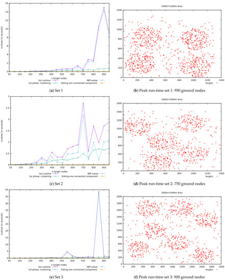
Figure 9.
Datasets overall run-time and specific to the 3 main steps; and distribution of instance with highest execution time (Part 1).
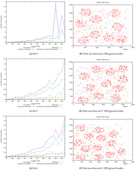
Figure 10.
Datasets overall run-time and specific to the 3 main steps; and distribution of instance with highest execution time (Part 2).
From these figures, one can already notice that run-time does not always grow with the number of targets to cover. Also, even though at some point the execution times of the three phases vary a lot and even intertwine, some important features are noticeable from the results:
- the cost of the clustering phase revolves on the number of targets but also on the distance between them, since the generated positions depend on these distances and thus the number of iterations until the stopping criterion is reached. This phase is the one with a relatively more consistent run-time growth that is unlikely to explode.
- the execution cost of the MIP solver depends on the number of targets (the constraints) and the positions generated in the first step (the decision variables), but it most importantly depends on the structure of the problem. Indeed, the branch-and-cut method used by glpk is most sensitive to the steps needed to reach the optimal integer solution than on the size of the problem.
- the time cost of the connectivity step depends on the gaps in the separate connected components.
The execution time expansion of the clustering phase is somewhat regular and takes less than two seconds for all the instances in the dataset. It grows with the number of targets and moderately fluctuates with the extent of separation between groups of targets. Moreover, compared to the other steps, it is the one that is less likely to increase drastically.
On the other hand, the second step can sometimes be considerably expensive, even for small numbers of targets. In Figure 9f for example, we see a very substantial increase for the instance of 900 targets, whereas for the previous and its next (950 and 1000 targets), the duration is much more moderate. That is due to the numbers of branching and cuts used to reach the optimal integer solution for that specific instance. That is why the structure of the input instance is more challenging for the solver than its size.
As for the last phase, it is obvious to expect seeing a sharp escalation in execution time for instances with large gaps within the different connected components. What is more interesting to observe for this phase, is the effect of using a type of greedy strategy as the one we used: for the connectivity, we have adopted as a solution to connect the two closest connected components. The greedy approach can sometimes make a detour and take a longer path, causing a generation of larger number of aircraft used only for connectivity. Such instance can be seen in Figure 11d where there are considerable numbers of aircraft dedicated just for connectivity (in green) than those used for coverage (in blue): 1114 aircraft for connectivity, vs 616 for coverage. This instance (1000 targets to cover) was part of an additional set of input tests used to examine the performance of our approach for the specific connectivity feature. Compared to the other sets of the second series of experiments, this new set of instances (“Large” in Figure 11a) had a much greater extent of expansion but still had the same pool of number of targets (50 to 1000). We can clearly notice in Figure 11b that on much larger maps the cost of connecting the connected components is the one that stands out the most. The detours caused by the greedy approach are also apparent in Figure 11d. From that graphical representation it is easy to realize that a better solution can be found.
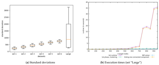
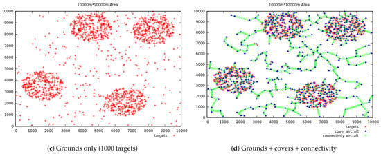
Figure 11.
Results on the dataset with large gaps between connected components.
7. Conclusions
In order to provide efficient solutions for the deployment of Unmanned Aircraft Systems (UASs) for ground targets communication provision in disaster scenarios, the present work proposed a solution providing a maximum coverage for targets on the ground and a guaranteed minimum number of covers for each target to ensure that in case of aircraft failures in the UAS, targets stay covered. However, also, in order to keep a steady stream of communication between the UAS and the ground targets, the approach provides a way of building networks that always form unique connected components. This report presented the method that works in three main phases: (1) Apply clustering methods to generate locations for the aircraft into good area of interest. This phase uses a procedure of building smaller clusters on each iteration to add more potential locations and diversify the search space for the next phase; (2) Run an optimization phase that filters the generated locations and keep only the ones that best satisfy two requirements: coverage and redundancy of the covers; (3) When necessary, build a unique connected component of the UAS by iteratively connecting the two closest separated connected components.
With the clustering method, we wanted to produce good and limited locations for the UASs, with the intention of using them as discrete data for a set cover type problem. The optimization phase then minimized the results from phase 1 by filtering them and keep only the best. This way of doing things has enabled us to offer maximum coverage for all the target nodes on the ground and guarantees a minimum k-coverage for each target with a low number of aircraft to deploy. Finally, if the results from phase 2 do not form a unique connected component, a last phase ensures that a single one is built from the spread ones. We tested our approach with different scenarios, and assessed its cost on several sets of instances, different by the number of targets to cover, as well as their distributions. The approach provided good results but most importantly in a very short period of time.
Still, at this stage of the work, we believe that the way connectivity is enforced into the UASs can be improved. Indeed, our approach builds a unique connected component with a greedy solution: connect the two closest aircraft in two different connected components. For this, a pairwise comparison of aircraft locations is required and it can get heavy as the number of aircraft increases. So, as a further assignment, it could be interesting to test new methods and draw ideas from others research work in order to tackle this issue. In many of the works presented in Section 1 and Section 2, the connectivity requirement is dealt with as a network flow problem and directly included as a constraint in an integer programming model. It can indeed be convenient to solve the whole process into a single model, but, if the search space for the connectivity cannot be discretized as it is done in the present work, the problem might certainly stay complex to handle and the solutions could hardly be scaled to larger instances. Exact and approximate methods like [9,15,16,28] propose to solve more objectives on larger scale but on the expense of computation time and sometimes even on the quality of the solutions. So, we believe that the present work could be a new addition to the research and could really benefit from other research too. The greatest benefit of the proposed approach is that it is modeled as a simple mono-objective optimization problem, which makes it really convenient to transform into a multiobjective model.
Author Contributions
Conceptualization, D.M.N., D.G.-R., S.L.T.M., H.T.; Methodology, D.M.N. and D.G.-R.; Resources, H.T. and S.L.T.M.; Software, D.M.N.; Supervision, D.G.-R., H.T. and S.L.T.M.; Validation, D.M.N.; Writing—original draft, D.M.N.; Writing—review and editing, D.G.-R., H.T. and S.L.T.M. All authors have read and agreed to the published version of the manuscript.
Funding
This work has been partially funded by the Universidad de Sevilla under the contract “Contratos de acceso al Sistema Español de Ciencia, Tecnología e Innovación para el desarrollo del programa propio de I+D+i de la Universidad de Sevilla”, by the Spanish “Ministerio de Ciencia, innovación y Universidades, Programa Estatal de I+D+i Orientada a los Retos de la Sociedad” under the Project “Despliegue Adaptativo de Vehículos no Tripulados para Gestión Ambiental en Escenarios Dinámicos RTI 2018-098964-B-I00”, and by the reginal goverment Junta de Andalucía under the Projects “Despliegue Inteligente de una red de Vehículos Acuáticos no Tripulados para la monitorización de Recursos Hídricos US-1257508”, “Despliegue y Control de una Red Inteligente de Vehículos Autónomos Acuáticos para la Monitorización de Recursos Hídricos Andaluces PY18-RE0009” and “Desarrollo de nuevas tecnologías WiFi inteligentes en entornos móviles y con alta densidad de usuarios P18-TP-1520”.
Conflicts of Interest
The authors declare no conflict of interest.
References
- Asimakopoulou, E.; Bessis, N.; Asimakopoulou, E.; Bessis, N. Advanced ICTs for Disaster Management and Threat Detection: Collaborative and Distributed Frameworks; Information Science Reference—Imprint of: IGI Publishing: Hershey, PA, USA, 2010. [Google Scholar]
- Reina, D.; Askalani, M.; Toral, S.; Barrero, F.; Asimakopoulou, E.; Bessis, N. A survey on multihop ad hoc networks for disaster response scenarios. Int. J. Distrib. Sens. Netw. 2015, 11, 647037. [Google Scholar] [CrossRef]
- Hayat, S.; Yanmaz, E.; Muzaffar, R. Survey on Unmanned Aerial Vehicle Networks for Civil Applications: A Communications Viewpoint. IEEE Commun. Surv. Tutorials 2016, 18, 2624–2661. [Google Scholar] [CrossRef]
- Gupta, L.; Jain, R.; Vaszkun, G. Survey of Important Issues in UAV Communication Networks. IEEE Commun. Surv. Tutorials 2016, 18, 1123–1152. [Google Scholar] [CrossRef]
- Sánchez-García, J.; García-Campos, J.; Arzamendia, M.; Reina, D.G.; Toral, S.; Gregor, D. A survey on unmanned aerial and aquatic vehicle multi-hop networks: Wireless communications, evaluation tools and applications. Comput. Commun. 2018, 119, 43–65. [Google Scholar] [CrossRef]
- Reina, D.G.; Toral, S.L.; Tawfik, H. UAVs Deployment in Disaster Scenarios Based on Global and Local Search Optimization Algorithms. In Proceedings of the 2016 9th International Conference on Developments in eSystems Engineering (DeSE), Liverpool, UK, 31 August–2 September 2016; pp. 197–202. [Google Scholar] [CrossRef]
- Galkin, B.; Kibilda, J.; DaSilva, L.A. Deployment of UAV-mounted access points according to spatial user locations in two-tier cellular networks. In Proceedings of the 2016 Wireless Days (WD), Toulouse, France, 23–25 March 2016; pp. 1–6. [Google Scholar] [CrossRef]
- Sánchez-García, J.; García-Campos, J.M.; Toral, S.L.; Reina, D.G.; Barrero, F. An Intelligent Strategy for Tactical Movements of UAVs in Disaster Scenarios. Int. J. Distrib. Sens. Netw. 2016, 12, 8132812. [Google Scholar] [CrossRef]
- Reina, D.G.; Tawfik, H.; Marín, S.L.T. Multi-subpopulation evolutionary algorithms for coverage deployment of UAV-networks. Ad Hoc Netw. 2018, 68, 16–32. [Google Scholar] [CrossRef]
- Gupta, S.K.; Kuila, P.; Jana, P.K. Genetic algorithm approach for k-coverage and m-connected node placement in target based wireless sensor networks. Comput. Electr. Eng. 2016, 56, 544–556. [Google Scholar] [CrossRef]
- Sabino, S.; Horta, N.; Grilo, A. Centralized Unmanned Aerial Vehicle Mesh Network Placement Scheme: A Multi-Objective Evolutionary Algorithm Approach. Sensors 2018, 18, 4387. [Google Scholar] [CrossRef] [PubMed]
- Caillouet, C.; Razafindralambo, T. Efficient Deployment of Connected Unmanned Aerial Vehicles for Optimal Target Coverage. In Proceedings of the IEEE GIIS 2017—Global Information Infrastructure and Networking Symposium, St. Pierre, France, 25–27 October 2017. [Google Scholar] [CrossRef]
- Yoon, Y.; Kim, Y. An Efficient Genetic Algorithm for Maximum Coverage Deployment in Wireless Sensor Networks. IEEE Trans. Cybern. 2013, 43, 1473–1483. [Google Scholar] [CrossRef] [PubMed]
- Konstantinidis, A.; Yang, K. Multi-objective K-connected Deployment and Power Assignment in WSNs using a problem-specific constrained evolutionary algorithm based on decomposition. Comput. Commun. 2011, 34, 83–98. [Google Scholar] [CrossRef]
- Gentili, M.; Raiconi, A. α-Coverage to extend network lifetime on wireless sensor networks. Optim. Lett. 2013, 7, 157–172. [Google Scholar] [CrossRef]
- Castaño, F.; Bourreau, E.; Velasco, N.; Rossi, A.; Sevaux, M. Exact approaches for lifetime maximization in connectivity constrained wireless multi-role sensor networks. Eur. J. Oper. Res. 2015, 241, 28–38. [Google Scholar] [CrossRef]
- Sánchez-García, J.; Reina, D.; Toral, S. A distributed PSO-based exploration algorithm for a UAV network assisting a disaster scenario. Future Gener. Comput. Syst. 2019, 90, 129–148. [Google Scholar] [CrossRef]
- Huang, C.F.; Tseng, Y.C. The Coverage Problem in a Wireless Sensor Network. Mob. Netw. Appl. 2005, 10, 519–528. [Google Scholar] [CrossRef]
- Karp, R.M. Reducibility among Combinatorial Problems. In Complexity of Computer Computations; Springer: Boston, MA, USA, 1972; pp. 85–103. [Google Scholar]
- Bradley, S.; Hax, A.; Magnanti, T. Applied Mathematical Programming; Addison-Wesley Publishing Company: Boston, MA, USA, 1977; pp. 272–319. [Google Scholar]
- Schweikardt, N. One-Pass Algorithm. In Encyclopedia of Database Systems; Springer: Boston, MA, USA, 2009; pp. 1948–1949. [Google Scholar] [CrossRef]
- Amini, M.R.; Gaussier, É.; Robertson, S.P. Recherche D’Information—Applications, Modèles et Algorithmes—Fouille de données, déCisionnel et Big Data; Eyrolles: Paris, France, 2013; Chapter 6; p. 165. [Google Scholar]
- Almeida, R.J.; Sousa, J.M.C. Comparison of fuzzy clustering algorithms for classification. In Proceedings of the 2006 International Symposium on Evolving Fuzzy Systems, Ambelside, UK, 7–9 September 2006; pp. 112–117. [Google Scholar] [CrossRef]
- Yu, J.; Qi, Y.; Wang, G.; Gu, X. A cluster-based routing protocol for wireless sensor networks with nonuniform node distribution. AEU Int. J. Electron. Commun. 2012, 66, 54–61. [Google Scholar] [CrossRef]
- Soro, S.; Heinzelman, W.B. Cluster head election techniques for coverage preservation in wireless sensor networks. Ad Hoc Netw. 2009, 7, 955–972. [Google Scholar] [CrossRef]
- Gearhart, J.L.; Adair, K.L.; Durfee, J.D.; Jones, K.A.; Martin, N.; Detry, R.J. Comparison of Open-Source Linear Programming Solvers; Technical Report; University of North Texas Libraries, Digital Library: Denton, TX, USA, 2013. [Google Scholar]
- Mackenzie, D.H. GNU Linear Programming Kit FAQ. 2004. Available online: https://www.cs.unb.ca/~bremner/docs/glpk/glpk_faq.txt (accessed on 9 January 2019).
- D’Andreagiovanni, F. On Improving the Capacity of Solving Large-scale Wireless Network Design Problems by Genetic Algorithms. Applications of Evolutionary Computation; Springer: Berlin/Heidelberg, Germany, 2011; pp. 11–20. [Google Scholar]
Publisher’s Note: MDPI stays neutral with regard to jurisdictional claims in published maps and institutional affiliations. |
© 2021 by the authors. Licensee MDPI, Basel, Switzerland. This article is an open access article distributed under the terms and conditions of the Creative Commons Attribution (CC BY) license (http://creativecommons.org/licenses/by/4.0/).