Abstract
This paper deals with high frequency analysis of spiral inductors, used in microelectronics circuits, to optimize their configuration. Software developed, designed, and implemented by the authors for nano and micrometre spiral inductor high frequency analysis, named ABSIF, is presented in this paper. ABSIF determines the inductance, quality factor, and electrical parameters for square, hexagonal, octagonal, and circular spiral inductors and their configuration optimization for energy efficiency. ABSIF is a good tool for spiral inductor design optimization in high frequency applications and takes into account the imposed technological limits and/or the designers’ constraints. A set of spiral inductors are considered and analysed for high frequency values using ABSIF, and the results are presented in the paper. The validation of ABSIF was completed by comparing the results with those obtained using a similar commercial software, Sonnet LiteTM, which is dedicated to high frequency electromagnetic analysis.
1. Introduction
Spiral inductors are the main pawns in microelectronic circuits, thanks to the possibility of reducing their dimensions at the micro and nanometre order and increasing their frequency at the GHz order. For high performance microelectronic circuits, it is necessary to improve the performance of their essential components, such as spiral inductors [1,2,3]. Spiral inductors have a crucial role in integrated circuits that work at very high frequencies. Spiral inductors are especially used in the design of miniature wireless power supply devices such as mobile or smartwatch chargers, wireless routers, wireless control and monitoring devices, wireless communication devices, radiofrequency amplifiers and converters, filters, antennas, and others [4,5,6,7,8,9,10,11]. Most of the next generation devices, apparatus, and equipment are based on radiofrequency micrometric integrated circuits. To improve their performance and to better understand them, the analysis of each constructive element of the integrated circuit, specifically of the spiral inductors integrated into radiofrequency microelectronic circuits [12,13], using proper tools and software, is of great interest to the designers and engineers of these circuits. The accurate calculation and extraction of spiral inductor electronic and electrical parameters, using adequate methods that do not require long computation time, excessive computational resources, or high effort, are necessary. The integrated circuits must be modelled and simulated to understand, study, and analyse their behaviour as well as highlight the phenomena and effects that occur at high frequency at micrometric geometries [14,15,16,17,18]. To achieve these, the following specific research objectives were met in this article: the extraction of inductance, quality factor, and electrical parameters for square, hexagonal, octagonal, and circular spiral inductors; the analysis of frequency and geometrical parameters influences on inductance and quality factor; planar spiral inductors configuration’s optimization for energy efficiency. For this reason, a software program that was developed, designed, and implemented by the authors and dedicated to spiral inductors high frequency analysis, named ABSIF, is presented in this article. The ABSIF software program allows inductance, quality factor, and electrical parameters extraction for square, hexagonal, octagonal, and circular spiral inductors and their configuration optimization for energetic efficiency. It is dedicated to high frequency application.
2. High Frequency Analysis of Spiral Inductors by Means of ABSIF Software
Compact software programs are needed for the analysis, design, and optimization of spiral inductors because the available software (i.e., Sonnet LiteTM [19]) typically does not allow analysis and optimization of spiral inductors in high frequency applications. The ABSIF software developed, implemented, and designed by the authors is a compact software program that can be used for high frequency spiral inductor analysis, optimization, and to determine the electronic and electrical parameters, inductance, and quality factor, optimizing their configuration for high performance applications. ABSIF allows the implementation of square, hexagonal, octagonal, and circular spiral inductors for high frequency analysis; these spiral inductor shapes are frequently used in radiofrequency microelectronic circuits [20]. The ABSIF software program has four modules: two modules for inductance, quality factor, and electronic/electrical parameters computation and two modules for spiral inductor optimization in high frequency applications. The first module of the program, CPEPDC, is dedicated to inductance, quality factor, and electronic/electrical parameter extraction for constant descriptive parameters. The second module, CPEPDV, extracts the inductance, quality factor, and electronic/electrical parameters for variable descriptive parameters. The third module, OCBSIM, optimizes the spiral inductor configuration for maximum inductance, and the fourth one, OCBSFCM, optimizes the spiral inductor configuration and maximizes the quality factor, aiming at their energy efficiency.
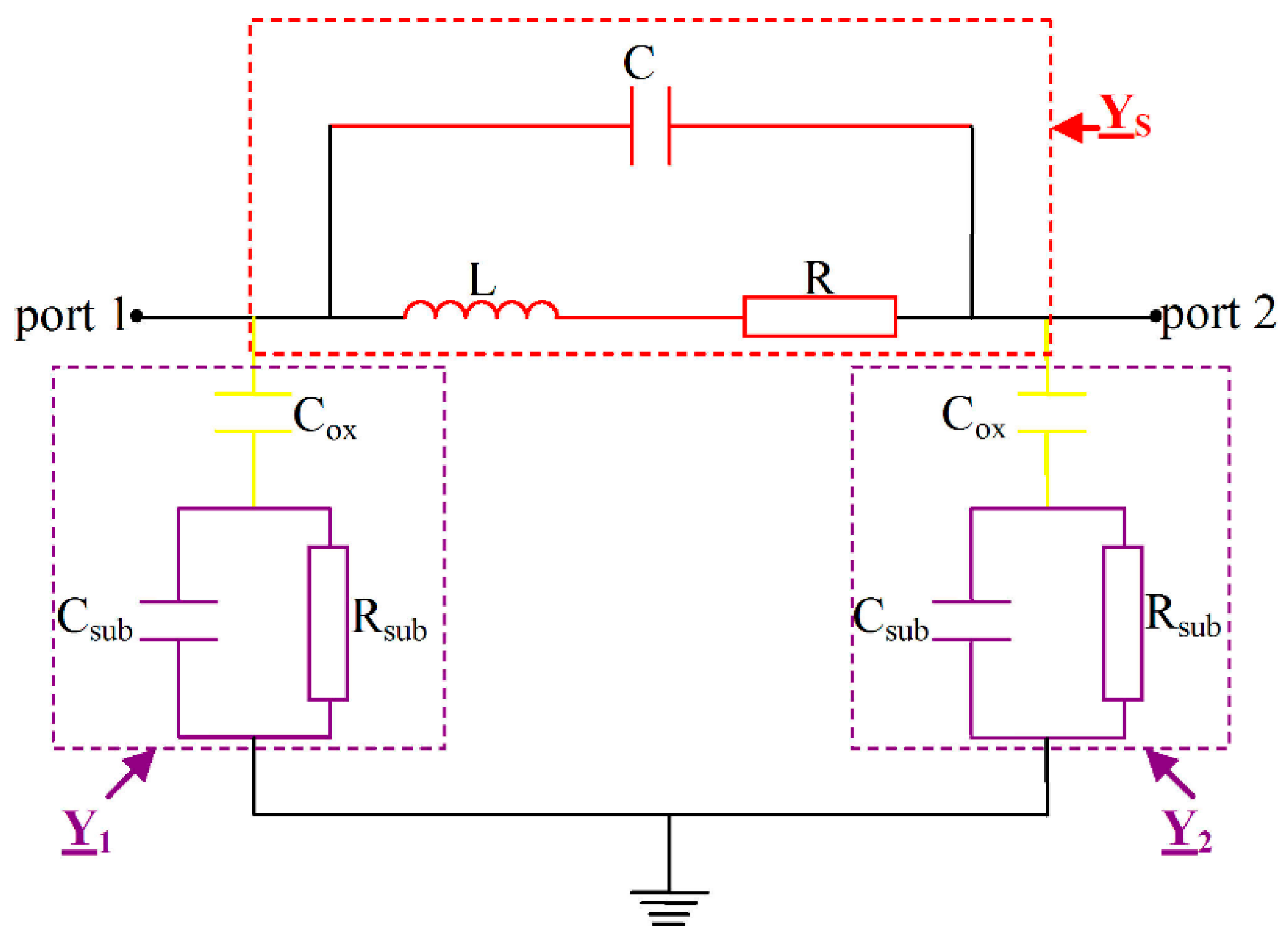
The ABSIF software is based on: analytical expressions for low frequency inductance calculations, based on the current sheet method [21,22,23,24,25,26,27]; analytical expressions for electrical parameters and for high frequency were set up by the authors using the π equivalent electrical circuit method. This method implies the use of π models with concentrated parameters for each side of the spiral inductor [28,29,30,31,32,33,34]. For example, a square inductor with N turns has 4N sides; each turn is formed of four lines and a π equivalent circuit with concentrated parameters, such as the one represented in Figure 1.
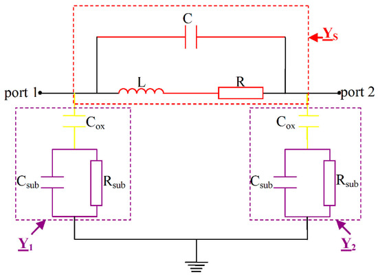
Figure 1.
The equivalent circuit for one side of the spiral inductor.
The model includes the following: the spiral series inductance, L; the series resistance, R; the capacitance between the spiral and the underpass, C; the capacitance between the spiral and the oxide layer, Cox; the substrate capacitance, Csub; the substrate resistance, Rsub.
The resistances and capacitances of the equivalent circuit have simple, intuitive, physical analytical expressions; only the inductance of the entire inductor implemented on the integrated circuit has no exact expression in high frequency and is determined by using the other parameters and frequency, based on the equivalent circuit reported in Figure 1. There is a difference between the spiral inductance, L, and the inductor high frequency inductance, Lf [35,36,37,38,39]. For high frequency applications, it is not enough to calculate the inductance of the spiral, as it is being placed in the air, so all the electrical parameters that appear (Figure 1) and, obviously, the frequency value must be considered. The high frequency inductor is characterized by its inductance, Lf, given by:
and its quality factor, Q, determined by:
where ω is the pulsation, f is the frequency, and is the input admittance:
when the port 2 is short circuited; then, due to the symmetry of the oxide layer and substrate geometries, and . The admittances of the element represented in Figure 1 are , , and .
The spiral admittance, , refers to the series admittances of the spiral inductor, composed of the inductors’ inductances and resistances in the series connection, and the capacitance between the spiral and underpass in parallel connection. The following expression is utilized for this admittance:
and are the admittances equivalent to the elements of the oxide layer and substrate. The admittance is:
We calculate in a similar manner.
The admittance is:
The optimal design procedure is formulated as an objective problem, which allows us to find the electrical parameters of the spiral inductors, the inductance, and quality factor. The objective is to find the optimal configuration of the spiral inductor, at maximum inductance L and quality factor Q, by satisfying the proper objective functions.
The objective function for the first optimization module is:
and for the second optimization module is:
where Lf max and Qmax are calculated using the above expressions.
2.1. CPEPDC Module
The module for the computation of the electrical parameters of spiral inductors, utilized in microelectronic circuits for constant descriptive parameters, the CPEPDC module, allows us to determine, for a high frequency analysis, the following parameters: spiral inductance, L; resistance, R; capacitance, C; oxide capacitance, Cox; substrate resistance, Rsub; capacitance, Csub; spiral inductor high frequency inductance, Lf; quality factor, Q.
The following are used as input data for the geometrical definition of the inductor in the module: the spiral shape; the number of turns, N; the turn’s width, w; the distance between turns, s; the external diameter, de; the internal diameter, di; the turn’s thickness, t; the via thickness, tc; the oxide thickness, to; the substrate thickness, ts. The frequency and the materials for each component of the spiral inductor must be properly set. The computed values of the electrical parameters, the inductance, and the quality factor are displayed in a window with the equivalent circuit, on which the parameter that is selected to be displayed is automatically highlighted.
A set of designed spiral inductors was analysed for high frequency values using our ABSIF software. All the spiral inductors were designed to be utilized on microelectronic circuits on the same area of 0.25 mm2. The geometrical parameters are the same for all the designed spiral inductors: the external diameter is 500 μm, the distance between the turns is 5 μm, the turn width is 10 μm, the turn thickness is 2 μm, the oxide layer thickness is 6 μm, the substrate thickness is 380 μm, the via thickness is 2 μm, and the underpasses thickness is 2 μm. We considered turn numbers from one to sixteen and frequencies from one to ten GHz for all the analyses. We assumed the use of copper for the spiral, silicon dioxide for the oxide layer, and silicon for the substrate. The CPEPDC module was implemented to compute the values of the electrical parameters of the spiral inductors, the inductance, and the quality factor for constant descriptive parameters, frequency, and number of turns. Table 1 shows the results obtained for the analysis of the set of designed square spiral inductors analysed at 4 GHz.

Table 1.
Results of analysed square spiral inductors at 4 GHz.
The ABSIF gives the results, immediately, for all the interest inductor’s parameters for the desired frequency. The spiral inductance increases with the number of inductor’s turns, but not with the inductor’s inductance, which depends on frequency and reaches its maximal value at its resonance frequency. In high frequency, there is not a linear increment of the inductance with the number of turns because of the different frequency resonance of each inductor. All the layers on which the spiral is constructed have an influence on the planar inductor parameters in high frequency, and all of these must be properly calculated and considered in their design and optimization.
Table 2 shows the results obtained for the analysis of the set of designed square spiral inductors analysed at 10 GHz. In this way, using our program, the inductor’s parameters can be properly found for a wide range of frequencies.
Table 2.
Results of analysed square spiral inductors at 10 GHz.
2.2. CPEPDV Module
The CPEPDV module of ABSIF for electrical parameters, inductance, and quality factor computation for variable descriptive parameters is similar to the CPEPDC module, and it also analyses the electrical parameters, the inductance, and the quality factor variations in terms of variable frequency, number of turns, and other descriptive geometrical parameters for the same shapes of the spiral inductor. This module of the program computes and displays, in a table, the inductance value and the quality factor value with reference to the parameter selected as variable. By using this module, it is possible to obtain the inductance and quality factor variation at high frequency without the necessity of a separate implementation and analysis of each inductor, and then, it is possible to directly collect the results and plot the desired variations. The designed spiral inductors are also analysed in this module to plot the inductance and the quality factor variations, directly, in the graphical representation module, with it not being necessary to use other programs to plot the results. The inductance is plotted in terms of frequency for the square spiral inductor with 3 turns in Figure 2a and for the one with 8 turns in Figure 2b.
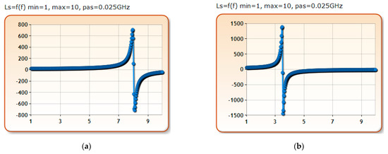
Figure 2.
The inductance variation vs. frequency for: (a) 5 and (b) 8 turns spiral inductors.
At a frequency variation between 1 and 10 GHz, as can be seen in Figure 2, the inductors each reach at a single or multiple resonance frequency, where the higher value of the inductance is found. If high-performance inductors are desired, they must also be properly analysed in terms of frequency. In ABSIF, these types of analyses are possible, for the all the inductors that were analysed in our research activities, we consider the frequency variation between 1 and 10 GHz, with the step 0.025 GHz. If it is desired, the step can be also smaller or higher than this. Each researcher can choose it in terms of the accuracy he wants for the results.
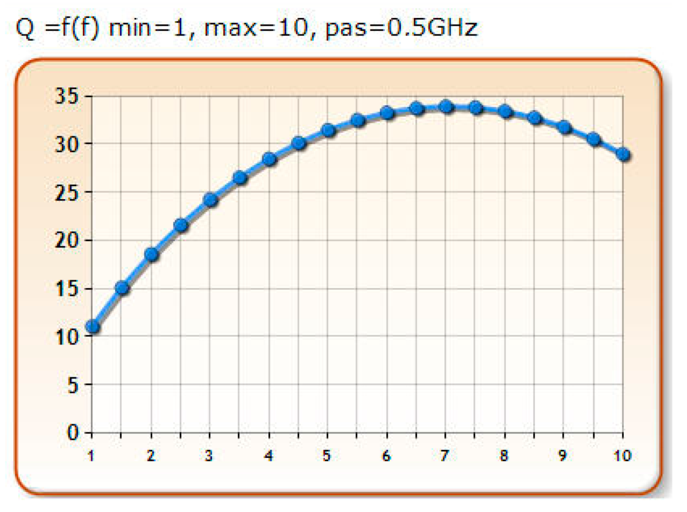
The quality factor variation, in terms of frequency, can also be plotted, directly, in this module of the software. For example, the quality factor is plotted, in terms of frequency, for the square spiral inductor, with 2 turns in Figure 3. The frequency varies between 1 and 10 GHz, with step 0.5. The frequency at which the quality factor is maximal can be found for inductor’s energy efficiency.
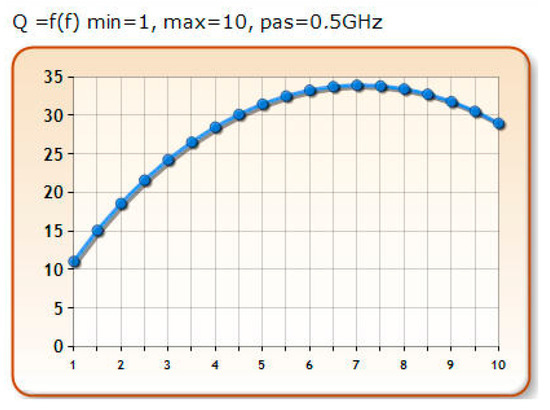
Figure 3.
The quality factor variation vs. frequency for 3 turns spiral inductors.
2.3. OCBSIM Module
The module for the optimization of the spiral inductor configuration for maximal inductance, the OCBSIM module, is dedicated to finding the optimal configuration of spiral inductors for the maximum inductance, given a particular area of implementation, on the microelectronic circuit.
The input data in this module are the spiral inductor shape (square, hexagonal, octagonal, or circular), the type of material, and the exterior diameter, de. This module of the program enables the use of additional optimization options. The software displays the value of maximal inductance, the frequency, and details about the optimal configuration that is found for the maximum inductance. The module automatically draws the cross section and top view of the optimal configuration.
The optimization module of the ABSIF program is a useful tool for spiral inductor design and optimization; it has a very friendly interface that facilitates the implementation, and the optimization process is easy to use. It also has short running time compared to similar programs.
Square spiral inductors with an exterior diameter of 10 μm, 50 μm, 100 μm, 200 μm, 300 μm, 500 μm, 700 μm, and 800 μm were optimized, and the optimal solution was found for each one to achieve the maximum inductance for a frequency range 1–10 GHz. Keeping the same shape of spiral inductors and the above detailed materials, the optimal configuration of these spiral inductors was found. The results are given for the analysed inductors in Table 3.
Table 3.
The optimal configuration for maximal inductance in 1–10 GHz frequency domain.
For these optimization processes, additional optimization options were considered. The program automatically draws the optimal configuration found for each implementation, so the designer can obtain the optimal configuration of the spiral inductor.
2.4. OCBSFCM Module
OCBSFCM is the module dedicated to the optimization of spiral inductor configuration for the maximum quality factor and energy efficiency. Given the area on which the spiral inductor will be implemented on the microelectronic circuit, this module of ABSIF helps obtain the optimal configuration of the inductor that has the maximum quality factor with high energy efficiency and high performance.
With the OCBFCM module of ABSIF, by using the same input data, the optimal solution for each spiral inductor in terms of high energy efficiency is obtained. For exterior diameters of 10 μm, 50 μm, 100 μm, 200 μm, 300 μm, 500 μm, 600 μm, and 800 μm, the optimal configuration for the maximum quality factor was obtained. The results for analysed inductors are shown in Table 4.
Table 4.
The optimal configuration for maximal quality factor in 1–10 GHz frequency domain.
3. Results and Discussion
The ABSIF software was validated by comparing the results with those obtained by using a similar commercial software, Sonnet LiteTM [19], for high frequency electromagnetic analysis. Different types of spiral inductors were implemented by using these software programs [21,22]. We intend, in the near future, to also validate our program with experimental measurements. We constructed some of the inductors analysed in our research activities and presented in this article, and we want to measure their Q and L by using a Network Analizer GHz.
This section presents the analysis for the designed set of square spiral inductors, with the dimensions and material properties given above. The inductance and the quality factor variations are analysed in the frequency domain 1–10 GHz. In Table 5, the results obtained by means of ABSIF are shown and compared to those obtained by Sonnet LiteTM for the set of square spiral inductors with 1–16 turns at 4 GHz frequency.
Table 5.
Comparison of the results obtained by ABSIF and Sonnet at 4 GHz.
The frequency analysis for the square spiral inductor with 2 turns was initially compared. The results obtained by using the two similar software programs, for inductance and quality factor variation is terms of frequency, are reported in Table 6.
Table 6.
L and Q vs. f for 2 turns spiral inductor at 4 GHz: comparison of the results obtained by ABSIF and Sonnet.
It is also very important to make the next comparison for a more complex spiral inductor and give the results for the square spiral inductor with 16 turns in the analysis of the inductance, and the quality factor variation in terms of frequency, in Table 7.
Table 7.
L and Q vs. f for 16 turns spiral inductor: comparison of the results obtained by ABSIF and Sonnet.
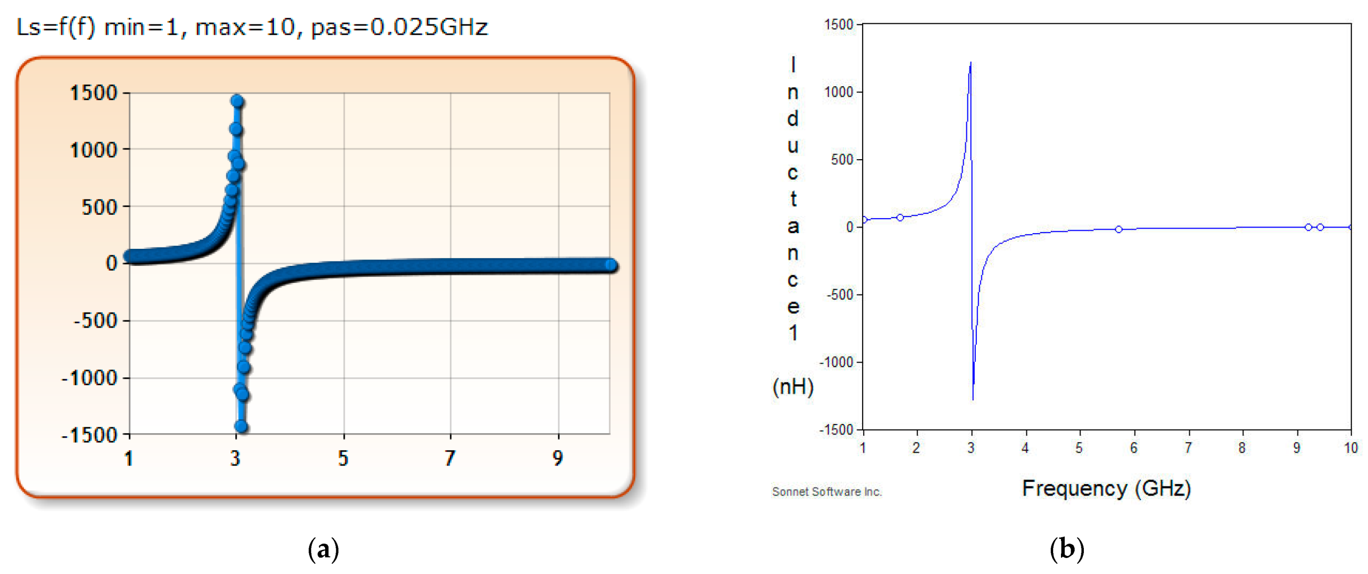
For a better visualization of the good agreements of the results, the results for the square spiral inductor with 16 turns were plotted separately in Figure 4, those obtained with ABSIF in Figure 4a, and those with Sonnet in Figure 4b for the same frequency variation between 1 and 10 GHz.
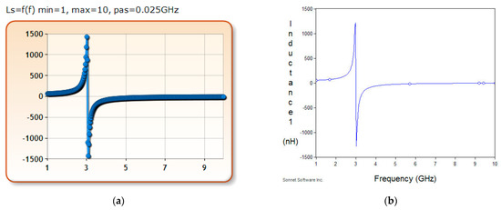
Figure 4.
Inductance variation, in terms of frequency for the square spiral inductor with 16 turns obtained by: (a) ABSIF software program; (b) Sonnet LiteTM.
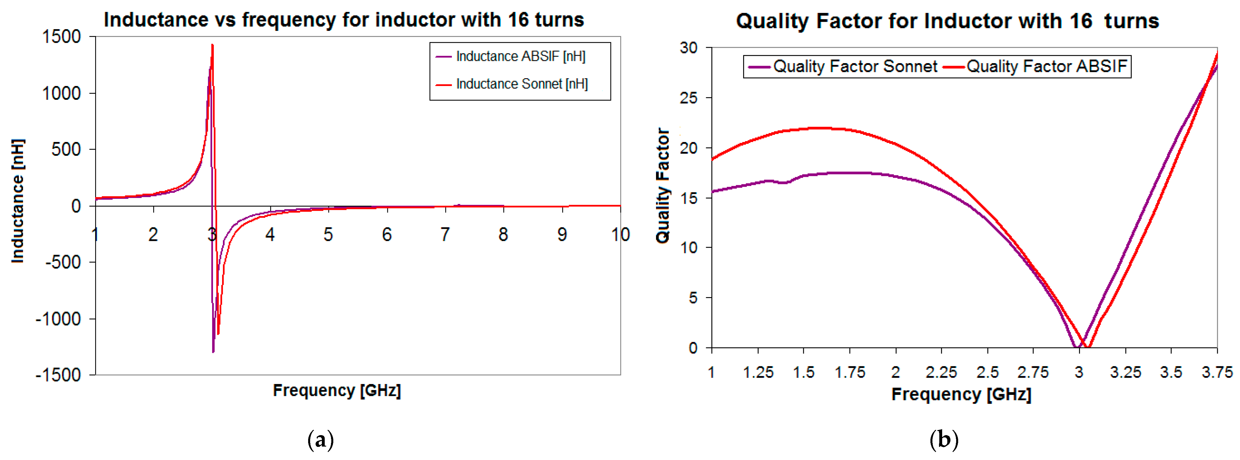
The results for inductance and quality factor, for the square spiral inductor with 16 turns, were compared and plotted in Figure 5. By overlaying the results, their good agreements are obvious.
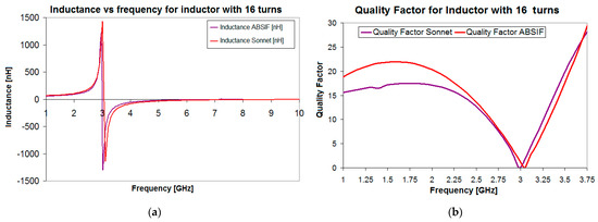
Figure 5.
Comparison of the results for 16 turns square spiral inductor: (a) inductance; (b) quality factor.
The ABSIF implementation immediately yielded the L and Q variations; each inductor was not analysed separately, as was necessary in the Sonnet software program, so the running times for ABSIF are much shorter than for similar programs.
The ABSIF program can be used with confidence for high frequencies analysis, modelling, simulation, design, and optimization of microelectronic planar spiral inductors of millimetre, micrometre and nanometre dimensions that operate at gigahertz order frequencies. The software is dedicated, exclusively, to spiral inductor high frequency analysis, so it can be used for parameter extraction for parametric inductor’s analysis (inductance variation in terms of frequency, in terms of some of the geometrical parameter, and so on) and for optimal design of the planar spiral inductor configuration with square, hexagonal, octagonal, and circular shapes.
4. Conclusions
The design of a spiral inductor requires a preliminary analysis for a proper high frequency to achieve high performance and to avoid errors. It is very important to have a software tool able to conduct this analysis as simply, easily, and quickly as possible while maintaining high accuracy.
In the present paper, ABSIF software was proposed, which is a well-assembled and well-structured software. Each module of the software is set for a specific computation or optimization to provide opportunities for all the studies that spiral inductor designers must conduct before, during, and after the construction of the spiral inductors. The geometrical parameters and materials used for the other components of the microelectronic circuits can affect the inductance and the quality factor values of spiral inductors and must be properly analysed to achieve inductors with high performances. Using the ABSIF software the planar spiral inductor can be very deeply analysed, their electrical parameters (resistances, capacitances, inductances) can be extracted easy and fast with high accuracy for a wide range of planar inductor types of millimetre, micrometre, and nanometre dimensions and in a wide range of high frequencies. The software allows us to directly analyse the inductor’s parameters variations in terms of frequency and/or in terms of geometrical parameters by plotting their variation in real time, as was exemplified in Figure 2, Figure 3 and Figure 4 and detailed in Table 6 and Table 7. A set of spiral inductors were designed to be analysed in high frequency to validate our ABSIF software and the obtained results, presented in Figure 5, show their accuracy.
The software program enables the analysis and optimization of a board range of spiral inductors. It is very good for spiral inductor design because it allows to compute its inductance, quality factor, and electrical parameters for high frequency applications with very good accuracy and to optimize the spiral inductor configuration for the imposed technological limits and/or for the designers’ needs.
In the present paper, we demonstrated that, by comparing the results obtained with other commercial software, the proposed software is of much help in the design, optimization, and verification of spiral inductors.
Author Contributions
Conceptualization, C.P., V.T., A.G. and C.M.; methodology, C.P., A.G. and C.C.; software, C.P.; validation, C.P., A.G., C.C., M.G. and S.A.; formal analysis, C.P.; investigation, C.P., V.T. and C.M.; resources, S.A. and M.G.; data curation, C.P., V.T. and C.M.; writing—original draft preparation, C.P.; writing—review and editing, C.P., A.G. and C.C.; visualization, S.A. and M.G.; supervision, V.T. and C.M.; project administration, C.P.; funding acquisition, C.P. All authors have read and agreed to the published version of the manuscript.
Funding
This research was funded by a grant of the Romanian National Authority for Scientific Research and Innovation, CNCS–UEFISCDI, project number PN-II-RU-TE-2014-4-0199.
Acknowledgments
This work was supported by a grant of the Romanian National Authority for Scientific Research and Innovation, CNCS–UEFISCDI, project number PN-II-RU-TE-2014-4-0199.
Conflicts of Interest
The authors declare no conflict of interest.
References
- Mohan, S.S.; Hershenson, M.M.; Boyd, S.P.; Lee, T.H. Simple accurate expressions for planar spiral inductors. IEEE J. Solid State Circuits 1999, 34, 1419–1424. [Google Scholar] [CrossRef] [Green Version]
- Niknejad, A.M.; Meyer, R.G. Analysis, design and optimization of spiral inductors and transformers for Si RFIC’s. IEEE J. Solid State Circuits 1998, 33, 1470–1481. [Google Scholar] [CrossRef] [Green Version]
- Beryl, R.; Vaithianathan, V.; Kirubaveni, S. Comparative analysis of various on-chip spiral inductors. In Proceedings of the International Conference on Communication and Signal Processing, Melmaruvathur, India, 3–5 April 2013; pp. 437–441. [Google Scholar]
- Zhang, C.; Guo, L.; Wang, L.-F.; Huang, J.-Q.; Huang, Q.-A. Passive wireless integrated humidity sensor based on dual-layer spiral inductors. Electron. Lett. 2014, 50, 1287–1289. [Google Scholar] [CrossRef]
- Sheng-Fan, Y.; Tzuen-Hsi, H. Design of Single-Turn Spiral Inductors with Embedding a Strong-Coupling LC Resonator for Interference Suppression. IEEE Trans. Electromagn. Compat. 2017, 59, 919–926. [Google Scholar]
- Nieuwoudt, A.; Massoud, Y. Optimizing the Design of Tunable Spiral Inductors for On-Chip Wireless Applications. In Proceedings of the IEEE Annual Wireless and Microwave Technology Conference, Clearwater Beach, FL, USA, 4–5 December 2006; pp. 1–5. [Google Scholar]
- Pieters, P.; Vaesen, K.; Brebels, S.; Mahmoud, S.F.; De Raedt, W.; Beyne, E.; Mertens, R.P. Accurate modeling of high-Q spiral inductors in thin-film multilayer technology for wireless telecommunication applications. IEEE Trans. Microw. Theory Tech. 2001, 49, 589–599. [Google Scholar] [CrossRef]
- Islam Ashraf, B.; Islam Syed, K.; Tulip Fahmida, S. Design and Optimization of Printed Circuit Board Inductors for Wireless Power Transfer System. In Proceedings of the IEEE Electronic Components & Technology Conference, San Diego, CA, USA, 26–29 May 2015; pp. 2175–2179. [Google Scholar]
- Tavakkolia, H.; Abbaspour-Sania, E.; Khalilzadegana, A.; Rezazadehb, G.; Khoei, A. Analytical study of mutual inductance of hexagonal and octagonal spiral planer coils. Sens. Actuators 2016, 247, 53–64. [Google Scholar] [CrossRef]
- Samanta, K.K.; Robertson, I.D. High Performance Compact Multilayer Circular Spiral Inductors in Advanced Photoimageable Technology. IEEE Trans. Compon. Packag. Manuf. Technol. 2014, 4, 1981–1988. [Google Scholar] [CrossRef] [Green Version]
- Dong, L.; Wang, L.-F.; Ren, Q.-Y.; Huang, Q.-A. Mutual Inductance Suppressed Stacked Inductors for Passive Wireless Multi-Parameter Sensors. IEEE Sens. 2014, 926–929. [Google Scholar] [CrossRef]
- Xu, X.; Li, P.; Cai, M.; Han, B. Design of Novel High-Q-Factor Multipath Stacked On-Chip Spiral Inductors. IEEE Trans. Electron. Devices 2012, 59, 2011–2018. [Google Scholar] [CrossRef]
- Lopez-Villegas, J.M.; Vidal, N.; Del Alamo, J.A. Optimized Toroidal Inductors Versus Planar Spiral Inductors in Multilayered Technologies. IEEE Trans. Microw. Theory Tech. 2017, 65, 423–431. [Google Scholar] [CrossRef]
- Gliga, M.; Racasan, A.; Munteanu, C.; Andreica, S.; Pacurar, C.; Topa, V.; Constantinescu, C. The Influence of Ferrite on the Spiral Inductors Inductance used for the Design of Wireless Power Systems. In Proceedings of the IEEE International Conference on Modern Power Systems, Cluj-Napoca, Romania, 6–9 June 2017; pp. 112–117. [Google Scholar]
- Andreica, S.; Pacurar, C.; Topa, V.; Adina, R.; Constantinescu, C.; Gliga, M. The Analysis of the Multilayer Spiral Inductors Parameters at High Frequency. In Proceedings of the IEEE International Conference on Modern Power Systems, Cluj-Napoca, Romania, 6–9 June 2017; pp. 125–130. [Google Scholar]
- Pacurar, C.; Topa, V.; Giurgiuman, A.; Munteanu, C.; Constantinescu, C.; Gliga, M.; Andreica, S. Planar spiral inductors parameter extraction needed to design a wireless power supply system. In Proceedings of the IEEE International Conference on Modern Power Systems, Cluj-Napoca, Romania, 16–17 June 2021; pp. 28–35. [Google Scholar]
- Andreica, S.; Munteanu, C.; Gliga, M.; Pacurar, C.; Giurgiuman, A.; Constantinescu, C. Design of multilayer spiral coils with different geometries to determine the inductance. In Proceedings of the IEEE International Conference and Exposition on Electrical and Power Engineering, Iasi, Romania, 22–23 October 2020; pp. 126–132. [Google Scholar]
- Racasan, A.; Pacurar, C.; Munteanu, C.; Constantinescu, C.; Andreica, S.; Dusa, S. High Frequency Analysis of Monolayer Spiral Inductors. In Proceedings of the International Conference on Optimization of Electrical and Electronic Equipment and Intl Aegean Conference on Electrical Machines and Power Electronics, Brasov, Romania, 25–27 May 2017; pp. 116–121. [Google Scholar]
- Available online: http://www.sonnetsoftware.com/support/manuals.asp (accessed on 30 October 2021).
- Pacurar, C.; Topa, V.; Racasan, A.; Munteanu, C.; Hebedean, C.; Rafiroiu, D.; Cislariu, M. High Frequency Modeling of Square Spiral Inductor. In Proceedings of the IEEE International Conference and Exposition on Electrical and Power Engineering EPE, Iasi, Romania, 16–18 October 2014; pp. 622–626. [Google Scholar]
- Pacurar, C.; Ţopa, V.; Racasan, A.; Munteanu, C. Inductance Calculation and Layout Optimization for Planar Spiral Inductors. In Proceedings of the IEEE OPTIM 2012, Brasov, Romania, 24–26 May 2012; pp. 225–232. [Google Scholar]
- Pacurar, C.; Topa, V.; Munteanu, C.; Racasan, A.; Hebedean, C. Studies of Inductance variation for Square Spiral Inductors using CIBSOC Software. Environ. Eng. Manag. J. 2013, 12, 1161–1169. [Google Scholar] [CrossRef]
- Murugesan, K.S.; Chernobryvko, M.; Zinal, S.; Rossi, M.; Ndip, I.; Boettcher, M.; Lang, K.D.; Wieland, M.; Goetze, C.; Halim, S.B.; et al. High Quality Integrated Inductor in Fan-out Wafer-Level Packaging Technology for mm-Wave Applications. In Proceedings of the 50th European Microwave Conference (EuMC), Utrecht, The Netherlands, 12–14 January 2021; pp. 89–92. [Google Scholar]
- Cheng, J.; Xia, B. A Parametric Model and Design of Integrated Passive Inductors. In Proceedings of the IEEE MTT-S International Wireless Symposium (IWS), Shanghai, China, 20–23 September 2020; pp. 1–3. [Google Scholar]
- Menicanin, A.; Lukovic, M.; Blaz, N.; Movrin, D.; Zivanov, L. Design and Fabrication of Ferrite Inductor Using 3D Printed Spiral Coil and Ferrite Disc. In Proceedings of the IEEE EUROCON 2019—18th International Conference on Smart Technologies, Novi Sad, Serbia, 1–4 July 2019; pp. 1–4. [Google Scholar]
- Saberhosseini, S.S.; Ganji, B.A.; Razeghi, A.; Mahmoudi, Z. Modeling & simulation of MEMS spiral inductor. In Proceedings of the 24th Iranian Conference on Electrical Engineering (ICEE), Shiraz, Iran, 10–12 May 2016; pp. 507–510. [Google Scholar]
- Raghunadh, M.V.; Abhay Narasimha, K.S. Geometry Optimization of Planar Spiral Inductors operating at 5G mid-band frequencies. In Proceedings of the IEEE International Conference for Innovation in Technology (INOCON), Bangluru, India, 6–8 November 2020; pp. 1–8. [Google Scholar]
- Jayaraman, S.S.; Vanukuru, V.; Nair, D.; Chakravorty, A. A Scalable, Broadband, and Physics-Based Model for On-Chip Rectangular Spiral Inductors. IEEE Trans. Magn. 2019, 55, 1–6. [Google Scholar] [CrossRef]
- Zhou, S.; Xu, L.; Lu, J.; Yang, Y. Simulation and Optimization of High Performance On-Chip Solenoid MEMS Inductor. In Proceedings of the 2018 19th International Conference on Electronic Packaging Technology (ICEPT), Shanghai, China, 8–11 August 2018; pp. 710–715. [Google Scholar]
- Elhajjami, I.; Benhala, B.; Bouyghf, H. Optimal Design of RF Integrated Inductors via Differential Evolution Algorithm. In Proceedings of the 2020 1st International Conference on Innovative Research in Applied Science, Engineering and Technology (IRASET), Meknes, Morocco, 16–19 April 2020; pp. 1–6. [Google Scholar]
- Mawuli, E.S.; Wu, Y.; Delanyo Kulevome, K.B.; Qingfeng, Z.; Zhao, C.; Liu, H.; Yu, Y.; Kai, K. Distributed Characterization of On-Chip Spiral Inductors for Millimeter-Wave Frequencies. In Proceedings of the 2020 IEEE MTT-S International Conference on Numerical Electromagnetic and Multiphysics Modeling and Optimization (NEMO), Hangzhou, China, 7–9 December 2020; pp. 1–4. [Google Scholar]
- Vanukuru, V.N.R. Enhanced Q Improvement in Rectangular Shaped Inductors with Tapered Spirals. In Proceedings of the 2018 IEEE MTT-S International Microwave and RF Conference (IMaRC), Kolkata, India, 28–30 November 2018; pp. 1–3. [Google Scholar]
- Jiamian, S.; Li, H.; Sifan, W.; Tiantong, X.; Hanqing, L.; Hanxiao, W.; Shuangzhi, X. Broadband Lumped-Element Parameter Extraction Method of Two-Port 3D MEMS In-Chip Solenoid Inductors Based on a Physics-Based Equivalent Circuit Model. Micromachines 2020, 11, 836. [Google Scholar] [CrossRef] [PubMed]
- Bao-Hua, Z.; Nam-Young, K.; Zhi-Ji, W.; Eun-Seong, K. On-Chip Miniaturized Bandpass Filter Using GaAs-Based Integrated Passive Device Technology for L-Band Application. Materials 2019, 12, 1–15. [Google Scholar]
- Haiyan, S.U.N.; Wenjun, S.U.N.; Ling, S.U.N.; Jicong, Z.H.A.O.; Jiaen, F.A.N.G.; Xiaoyong, M.I.A.O. Model and Analysis of Planar Spiral Inductor Based on Package Substrate. In Proceedings of the 19th International Conference on Electronic Packaging Technology (ICEPT), Shanghai, China, 8–11 August 2018; pp. 1227–1231. [Google Scholar]
- Andreia, F.; Luís, M.; Carlos, F.; Filipe, A.; Jorge, C. A Fast and Precise Tool for Multi-Layer Planar Coil Self-Inductance Calculation. Sensors 2021, 21, 1–18. [Google Scholar]
- Ruixin, L.; Yifeng, W.; Qing, C.; Fuqiang, H.; Zhun, M. Entire Magnetic Integration Method of Multi-Transformers and Resonant Inductors for CLTLC Resonant Converter. Electronics 2020, 9, 1386. [Google Scholar] [CrossRef]
- Racasan, A.; Munteanu, C.; Pacurar, C.; Topa, V.; Constantinescu, C.; Pop, F.; Andreica, S.; Cislariu, M. Analysis, identification and minimization the parasitic effects of the multilayer spiral inductors. In Proceedings of the International Conference and Exposition on Electrical and Power Engineering, Iasi, Romania, 20–22 October 2016; pp. 392–397. [Google Scholar]
- Maroli, G.; Fontana, A.; Pazos, S.M.; Palumbo, F.; Julián, P. A Geometric Modeling Approach for Flexible, Printed Square Planar Inductors under Stretch. In Proceedings of the Argentine Conference on Electronics (CAE), Bahia Blanca, Argentina, 11–12 March 2021; pp. 61–66. [Google Scholar]

Publisher’s Note: MDPI stays neutral with regard to jurisdictional claims in published maps and institutional affiliations. |
© 2021 by the authors. Licensee MDPI, Basel, Switzerland. This article is an open access article distributed under the terms and conditions of the Creative Commons Attribution (CC BY) license (https://creativecommons.org/licenses/by/4.0/).