Abstract
This article presents compact and novel shape ring slotted antenna array operating at mmWave band on central frequency of 28 GHz. The proposed structure designed at 0.256 mm thin Roggers 5880 is composed of a ring shape patch with a square slot etched at the top mid-section of partial ground plane. Through optimizing the ring and square slot parameters high bandwidth of 8 GHz is achieved ranging from 26 to 32 GHz with simulated gain of 3.95 dBi and total efficiency of 96% for single element. The proposed structure is further transformed in a 4 element linear array manner. With compact dimensions of 20 mm × 22 mm for array, the proposed antenna delivers high simulated gain of 10.7 dBi and is designed in such a way that it exhibits dual beam response over the entire band of interest and simulated results well agree with fabricated prototype measurements.
1. Introduction
5G technology offers immense high data rate characteristics with low latency over whole communication channel. Divided into two bands, 5G technology focuses on Sub6GHz with different sub bands, such as LTE band 42 (3.4–3.6), band 43 (2.6–2.8), etc., but Sub6GHz spectrum is already choking up with enormous burden of microwave applications. This leads to the second dedicated mmWave spectrum which has unlimited bandwidth to be utilized [1,2]. WWith available feasibility reports, it is note worthy that mmWave range communication is a promising candidate for providing wider bandwidth, low latency, and higher data throughputs. In mmWave band, numerous bands have been assigned as possible candidate for future 5G standards, such as, 28 GHz and 38 GHz band, while 57–64 GHz (O2 band), and 164–200 (H2O band) have been declared as unlicensed frequency bands [3,4].
An infinity shell shape four element multiple input multiple output (MIMO) antenna array is presented in [5]. This system is operating at the central frequency of 28 GHz and is designed for mmWave 5G applications. In this work, the elements are arranged in such a manner that they provide spatial and pattern diversity characteristics but with low realize gain of 5.5 dBi. Similarly, in [6] mmWave antenna array is presented featuring a dual band on 28 and 38 GHz band. The four element MIMO array is arranged in orthogonal mannar providing directive patterns at both dual resonances but the bandwidth response is extremely low for 5G applications and services. In mmWave band, the attenuation and path losses become critical since the wavelength becomes extremely small. This issues can be overcome with high-gain antenna arrays compensating propagation and attenuation losses. Substrate Integrated Waveguides (SIW) are known to have low transmission line losses. A Hexagon loop shape SIW four element array is presented in [7], which provides broadband radiation characteristics with a high gain of 12 dBi. Similarly, in [8] having large impedance bandwidth of 16.5% at 28 GHz antenna is reported with SIW cavity-backed configuration. The overall size of array is (23 mm × 22.4 mm) small but the use of combination of series and parallel SIW-feed mechanism to excite different modes has made the reported structure complex by nature. In [9], an 8 element SIW cavity backed antenna array is presented with extremely low side-lobe levels. The reported antenna provides good radiation patterns and gain of around 13 dBi but the bandwidth of 2.3 GHz is attained only with large size of 63.5 × 70 mm2.
Planar antenna arrays on the other hand provides simple structure characteristics and are easy to assemble which have transmission line losses but they can be neglected with careful modelling [10,11,12,13,14]. A 9 element phased array is reported in [15], that exhibites gain of nearly 15 dBi. The structure is simple with small size of 400 mm2 ut the offered bandwidth is very low. In a similar study [16], a simple planar microstrip phased array antenna operating at 28 GHz is presented. It has a high gain of 15.6 dBi and 1.7 GHz bandwidth with a small 20 × 20 mm2 size. A two element MIMO planar structure in [17] with relative size of 26 × 11 mm2 resonates at two different mmWave allocated bands of 27 GHz and 39 GHz but the offered gain of the antenna is 5 dB which is low for mmWave systems. For mmWave systems, wide bandwidth and high gain is necessary in order to overcome atmospheric pressures and multipath fading effects.
As discussed earlier, for 5G technology characteristics, such as, high gain, wide bandwidth, and low latency, it is necessary to overcome challenges, such as, multipath fading and atmospheric pressure, therefore it is reasonable to study and propose a system that can address these challenges efficiently, and this is the motivation behind this work. In this work, a low-cost, simple, and easy to fabricate, non-complex, and integrateable planar structure with simple microstrip feed network is proposed. This research presents a novel, yet simple planar structure with simple feed network of 4 element array for mmWave applications. The emphasis here is on a simple and low-cost system that should not add complexity to the system when integrated. In literature review, we have discussed that although SIW based system are available but they are complex and hard to integrate. Therefore, there is need of such simple and easy to fabricate antenna systems. It is worthy to mention that, this system has dual beam radiation response on the front and the back face, and a peak gain of above 11 dBi, therefore it is believed that the proposed array can find its applications in the future mmWave broadband applications.
2. Antenna Design
Before presenting the proposed antenna array as shown in Figure 1, first, design, working principle, and results for a single element are presented. The aim here is to understand the working of the proposed system at the fundamental level and discuss how the final product is achieved. The single element is designed on a Rogers-5880 substrate having relative permittivity of 2.2, and loss tangent of 0.0009. The total size of the single element is mm3, while the thickness of the copper is 0.035 mm. The single element consists of a feed line, a donut-shaped radiating element, and a partial square-slotted ground plane. The design parameters for the single element are given in Table 1.
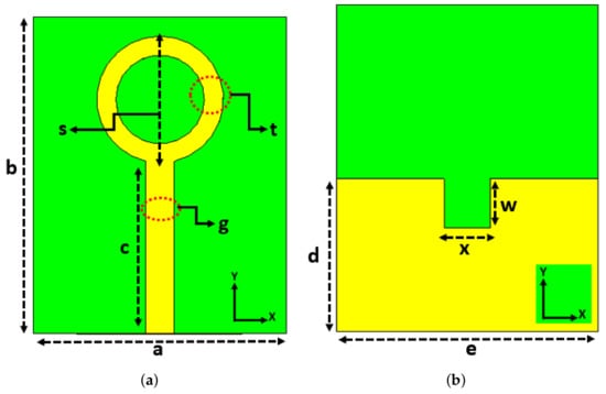
Figure 1.
Proposed Antenna Design. (a) Front View. (b) Back View.

Table 1.
Design Parameters.
Figure 2 illustrates the evolution of the single elements. First, a stub is designed and reflection coefficient is observed. Then, a circle is added at the end of the stub to make the antenna resonates within the desired frequency range. Finally, another circle is added within the previous circle and subtracted. This design resonates at 28 GHz with 6 GHz bandwidth ranges from 26 GHz to 32 GHz, as shown in Figure 2. Please note that, while designing the model, the ground plane was partial and a square-shaped slot was removed. This single element works as a simple circular patch antenna but the ground plane is partial. This is done to achieve dual radiation patterns within desired frequency range.
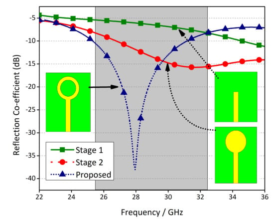
Figure 2.
Four stage Design Evolution.
The surface current distribution for a single element is shown in Figure 3. Next, a few parametric studies are performed to learn the effects of different design variables on the performance of the antenna specifically, on the S-parameters, as shown in Figure 4. First, the width between the two circles is varied to see the change in the scattering parameters. The variable t is varied between 1.2 mm and 1.4 mm with an interval of 0.1 mm. It is observed that as we increase the width, the frequency shifts from higher end of the band to the lower of the band and also the impedance of the antenna improves providing better matching, as depicted in Figure 4a. Similarly, to understand the effect of the rectangular shaped slot in the ground plane, a variable x is varied for five different values ranges between 1.3 mm to 1.7 mm.
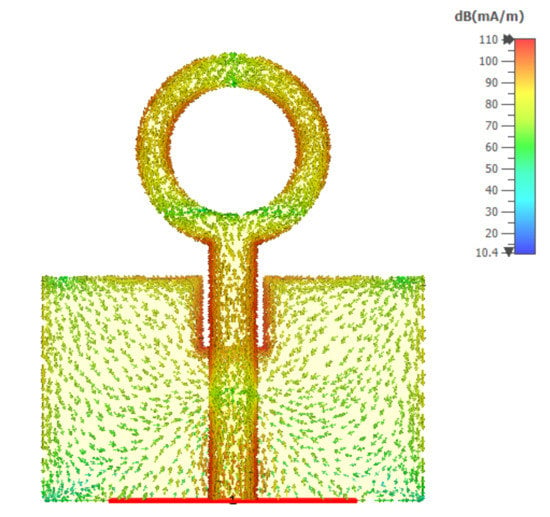
Figure 3.
Surface Current Distributions.
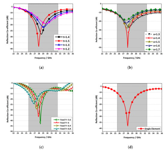
Figure 4.
Reflection Co-efficient. (a) Strip 1 sweep. (b) Strip 2 sweep. (c) Feed length sweep. (d) Final Single Element.
It is found that this variable can be used to obtain better impedance matching between the antenna and the feeding port, as illustrated in Figure 4b. Finally, the length of the feed is studied and its effect on the performance of the antenna is depicted in Figure 4c. As we increase the length of the feed, the antenna resonates at the lower side of the band. This is due to the fact that the electrical length and the physical length of the antenna is being increase and that is why it is resonating at the lower frequency. Once the parametric study is done and optimum parameters are selected, then the s-parameters of the final single element are shown in Figure 4d.
The radiation and total efficiency and gain of the proposed single element are shown in Figure 5. Please note that the efficiency is more than 90% while the gain is around 4 dBi. Next, different key performance parameters of the proposed antenna array are discussed in detail.
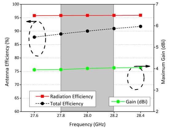
Figure 5.
Performance parameters of the proposed Antenna.
As discussed earlier, based on the reasonable performance of the single element, a linear array is designed using a simple feed structure. The feed line consists of a 50 Ω transmission line that divides into parallel connection of 100 Ω and then finally into 70 Ω lines, as illustrated in Figure 6. This structure is designed using a full electromagnetic wave computer software CST, fabricated using LPKF D104 milling machine, and measured using Anritsu vector network analyzer (VNA). The fabricated prototype is shown in Figure 7.
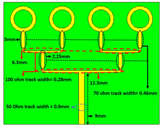
Figure 6.
Linear array transformation of proposed antenna.
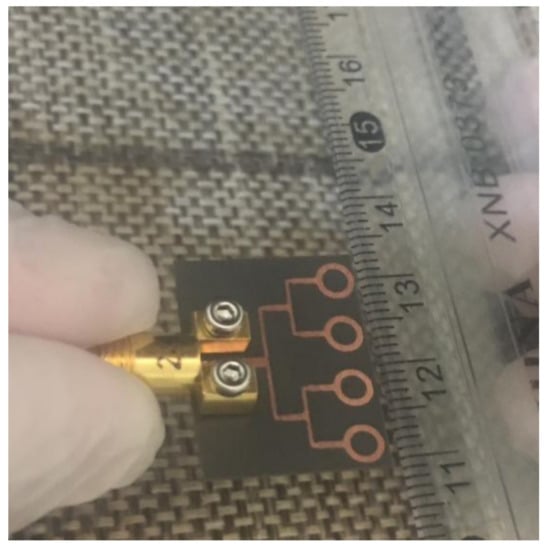
Figure 7.
Fabricated Prototype.
3. Results and Discussion
A comparison between the experimental and the simulated reflection coefficient for the feed port is shown in Figure 8. The results obtained agree very well. However, minor inconsistencies occur due to errors in fabrication as well as the unavoidable use of coaxial cables during the measurement of the antenna. In Figure 9, the surface current distribution for the antenna system is illustrated at 28 GHz. Please note that the current is distributed symmetrically between the radiating elements.
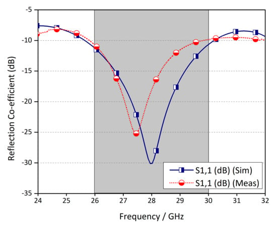
Figure 8.
Simulated and Measured reflection co-efficient of proposed Antenna Array.
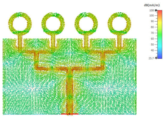
Figure 9.
Surface Current Distribution of Array.
The simulated and the measured far-field fields of the system for and are shown in Figure 10. It is worthy to mention that the fields radiated by the antenna in -plane are almost round with a null . Similarly, the pattern in the -plane is directive with a beamwidth of . This far-field profile suggests that it can be used for 5G technologies where the front and the back with the same radiation characteristics are required. Moreover, a 3-D far-field pattern for the proposed system is depicted in Figure 11 for a perspective view. In addition, measured and simulated gain and efficiency are shown in Figure 12. The measured gain is more than 9 dBi within the desired frequency bandwidth, while the efficiency is around 90%. Therefore, one can conclude that with these attributes the proposed system will find its applications in the future 5G systems and subsystems.
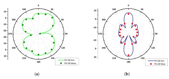
Figure 10.
Radiation Patterns Simulated and Measured. (a) Phi 90. (b) Phi 00.
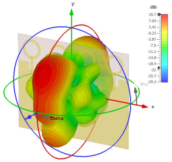
Figure 11.
3D Gain of proposed array at 28 GHz.
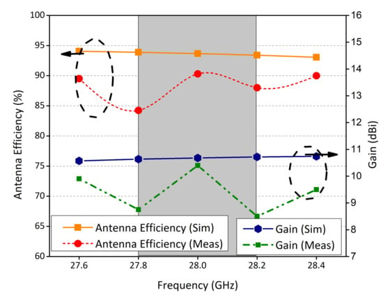
Figure 12.
Performance parameter of proposed Array.
To further demonstrate the advantages of this work with the available literature, a brief comparison in Table 2 has been drawn and it is observed that this work has advantage interms of size and key performance parameters.

Table 2.
Comparison Table.
4. Conclusions
In this work, a simple, efficient, low-cost, and easy to fabricate and integrate antenna system for 5G technologies is proposed. The proposed structure designed to resonate at central frequency of 28 GHz is composed of a ring shape patch with a square slot etched at the top mid-section of partial ground plane. The proposed structure is transformed into four element array with feed network for enhance performance characteristics. The proposed system has 90% efficiency, more than 10 dBi gain, and dual beam far-field profile. A prototype is fabricated to verify the simulated results and excellent agreement is observed between the measured and the computed results. Based on these attributes, it is believed that this system will find its applications in the future 5G systems and subsystems.
Author Contributions
Conceptualization, M.M.K., S.H.K. and M.A.; methodology, M.M.K., S.Y. and M.A.; software, S.H.K. and M.R.A; validation, M.R.A., S.Y. and A.J.; formal analysis, M.R.A. and M.A.; investigation, Z.A.A.; resources, M.A.; data curation, A.J.; writing—original draft preparation, A.L., S.H.K. andM.A.; writing—review and editing, A.J., A.L. and M.A.; visualization, M.R.A., S.H.K. and M.A.; supervision, E.L. and S.Y.; project administration, M.A., A.L. and S.H.K.; funding acquisition, M.A. and E.L. All authors have read and agreed to the published version of the manuscript.
Funding
This research received no external funding.
Data Availability Statement
All the material conducted in the study is mentioned in article.
Conflicts of Interest
The authors declare no conflict of interest.
References
- Zhang, J.; Yu, X.; Letaief, K.B. Hybrid beamforming for 5G and beyond millimeter-wave systems: A holistic view. IEEE Open J. Commun. Soc. 2019, 1, 77–91. [Google Scholar] [CrossRef]
- Kiani, S.H.; Altaf, A.; Abdullah, M.; Muhammad, F.; Shoaib, N.; Anjum, M.R.; Damaševičius, R.; Blažauskas, T. Eight Element Side Edged Framed MIMO Antenna Array for Future 5G Smart Phones. Micromachines 2020, 11, 956. [Google Scholar] [CrossRef] [PubMed]
- Przesmycki, R.; Bugaj, M.; Nowosielski, L. Broadband Microstrip Antenna for 5G Wireless Systems Operating at 28 GHz. Electronics 2021, 10, 1. [Google Scholar] [CrossRef]
- Hilt, A. Availability and Fade Margin Calculations for 5G Microwave and Millimeter-Wave Anyhaul Links. Appl. Sci. 2019, 9, 5240. [Google Scholar] [CrossRef]
- Kamal, M.M.; Yang, S.; Ren, X.c.; Altaf, A.; Kiani, S.H.; Anjum, M.R.; Iqbal, A.; Asif, M.; Saeed, S.I. Infinity Shell Shaped MIMO Antenna Array for mm-Wave 5G Applications. Electronics 2021, 10, 165. [Google Scholar] [CrossRef]
- Raheel, K.; Altaf, A.; Waheed, A.; Kiani, S.H.; Sehrai, D.A.; Tubbal, F.; Raad, R. E-Shaped H-Slotted Dual Band mmWave Antenna for 5G Technology. Electronics 2021, 10, 1019. [Google Scholar] [CrossRef]
- Ullah, H.; Tahir, F.A. A broadband wire hexagon antenna array for future 5G communications in 28 GHz band. Microw. Opt. Technol. Lett. 2019, 61, 696–701. [Google Scholar] [CrossRef]
- Choubey, P.N.; Hong, W.; Hao, Z.C.; Chen, P.; Duong, T.V.; Mei, J. A wideband dual-mode SIW cavity-backed triangular-complimentary-split-ring-slot (TCSRS) antenna. IEEE Trans. Antennas Propag. 2016, 64, 2541–2545. [Google Scholar] [CrossRef]
- Park, S.J.; Shin, D.H.; Park, S.O. Low side-lobe substrate-integrated-waveguide antenna array using broadband unequal feeding network for millimeter-wave handset device. IEEE Trans. Antennas Propag. 2015, 64, 923–932. [Google Scholar] [CrossRef]
- Ullah, H.; Tahir, F.A. A Novel Snowflake Fractal Antenna for Dual-Beam Applications in 28 GHz Band. IEEE Access 2020, 8, 19873–19879. [Google Scholar] [CrossRef]
- Zhang, J.; Ge, X.; Li, Q.; Guizani, M.; Zhang, Y. 5G millimeter-wave antenna array: Design and challenges. IEEE Wirel. Commun. 2016, 24, 106–112. [Google Scholar] [CrossRef]
- Yang, B.; Yu, Z.; Dong, Y.; Zhou, J.; Hong, W. Compact tapered slot antenna array for 5G millimeter-wave massive MIMO systems. IEEE Trans. Antennas Propag. 2017, 65, 6721–6727. [Google Scholar] [CrossRef]
- Shoaib, N.; Shoaib, S.; Khattak, R.Y.; Shoaib, I.; Chen, X.; Perwaiz, A. MIMO antennas for smart 5G devices. IEEE Access 2018, 6, 77014–77021. [Google Scholar] [CrossRef]
- Jilani, S.F.; Alomainy, A. Millimetre-wave T-shaped antenna with defected ground structures for 5G wireless networks. In Proceedings of the 2016 Loughborough Antennas & Propagation Conference (LAPC), Loughborough, UK, 14–15 November 2016; pp. 1–3. [Google Scholar]
- Khalily, M.; Tafazolli, R.; Rahman, T.; Kamarudin, M. Design of phased arrays of series-fed patch antennas with reduced number of the controllers for 28-GHz mm-wave applications. IEEE Antennas Wirel. Propag. Lett. 2015, 15, 1305–1308. [Google Scholar] [CrossRef]
- Ullah, H.; Tahir, F.A. A high gain and wideband narrow-beam antenna for 5G millimeter-wave applications. IEEE Access 2020, 8, 29430–29434. [Google Scholar] [CrossRef]
- Ali, W.; Das, S.; Medkour, H.; Lakrit, S. Planar dual-band 27/39 GHz millimeter-wave MIMO antenna for 5G applications. Microsyst. Technol. 2021, 27, 283–292. [Google Scholar] [CrossRef]
Publisher’s Note: MDPI stays neutral with regard to jurisdictional claims in published maps and institutional affiliations. |
© 2021 by the authors. Licensee MDPI, Basel, Switzerland. This article is an open access article distributed under the terms and conditions of the Creative Commons Attribution (CC BY) license (https://creativecommons.org/licenses/by/4.0/).