Article

The Effect of EMI Generated from Spread-Spectrum-Modulated SiC-Based Buck Converter on the G3-PLC Channel

1
Institute of Automatics, Electronics and Electrical Engineering, University of Zielona Gora, 65-417 Zielona Góra, Poland
2
Electrical Engineering, Mathematics and Computer Science (EEMCS), University of Twente, AE 7500 Enschede, The Netherlands
3
George Green Institute for Electromagnetics Research, University of Nottingham, Nottingham NG7 2RD, UK
4
Department of Electronics and Telecommunications Torino, Politecnico di Torino, 10129 Turin, Italy
*
Author to whom correspondence should be addressed.
Electronics 2021, 10(12), 1416; https://doi.org/10.3390/electronics10121416
Submission received: 10 May 2021 / Revised: 10 June 2021 / Accepted: 11 June 2021 / Published: 12 June 2021
(This article belongs to the Special Issue Electromagnetic Interference and Compatibility, Volume II)

Abstract

:
Power line communication (PLC) is increasingly emerging as an important communication technology for the smart-grid environment. As PLC systems use the existing infrastructure, they are always exposed to conducted electromagnetic interference (EMI) from switching mode power converters, which need to be tightly controlled to meet EMC regulations and to ensure the proper operation of the PLC system. For this purpose, spread-spectrum modulation (SSM) techniques are widely adopted to decrease the amplitude of the generated EMI from the power converters so as to comply with EMC regulations. In this paper, the influence of a spread-spectrum-modulated SiC-based buck converter on the G3-PLC channel performance is described in terms of channel capacity reduction using the Shannon–Hartley equation. The experimental setup was implemented to emulate a specific coupling path between the power and communication circuits and the channel capacity reduction was evaluated by the Shannon–Hartley equation in several operating scenarios and compared with the measured frame error rate. Based on the obtained results, SSM provides the EMI spectral peak amplitude reduction required to pass the electromagnetic compatibility (EMC) tests, but results in increased EMI-induced channel capacity degradation and increased transmission error rate in PLC systems.

1. Introduction

Nowadays, using of the smart-grid has increased due to the increase in renewable energy resources and the remarkable enhancements in the reliability of the electrical network grid. Thus, communication between smart-grid elements is essential to ensure the proper operation of the grid. In the complex smart-grid and micro-grid environment, the power line communication (PLC) is one of the most common techniques used for smart-meter applications [1], as it uses the existing power cables in the system to provide data transmission capabilities.
Using existing power cables for data transmission, PLC leads to reduced investment and maintenance costs. The smart-meters use the narrowband PLC following the European Norm (EN) 50065 that was established by CENELEC in 1992 [2]. Many industries begin the development of a PLC solution based on the regulation G3-PLC that has been established by the G3-PLC Alliance, while the industry specification PRIME (Power-line Related Intelligent Metering Evolution) has been developed by the PRIME Alliance [3,4]. However, many problems could influence the PLC performance.
Indeed, most switching-mode power converters utilize a switching frequency in the CISPR A band between 9 and 150 kHz. Consequently, the generated EMI lies in the same frequency band of the PLC that follows the CENELEC frequency band (from 3 to 150 kHz) [2,5]. EMI is coupled from the power circuit (the source of EMI) to the communication circuit (the victim) due to the presence of a parasitic coupling path between both circuits. EMI causes a decrease in the signal-to-noise ratio (SNR) below the level of noise-free communication, leading to data transmission error and sometimes failure of the communication [6]. Thus, a great deal of research has introduced utilizing wideband semi-conductors like silicon carbide (SiC) and gallium nitrite (GaN) [7,8], for the advantage of low switching losses and the high switching frequency capability (over 100 kHz), which could be one possible solution to overcome the overlapping in the frequency band. However, the high switching frequency increases the level of EMI in the high-frequency ranges [9,10,11,12]. In addition, the shape and nature of the interference signal out of the PLC band, which does not affect the SNR directly, are crucial for its potential impact on communication errors. Therefore, many researchers choose an experimental approach to study the impact of real sources (power electronic converters) on the operation of existing communication systems [13,14,15].
In the same framework, many researches aim at the application of spread-spectrum modulation (SSM) techniques on power converters as a suitable method of EMI mitigation, as SSM spreads EMI power into a wider band of frequencies so as to significantly reduce the EMI amplitude at the harmonics of the switching frequency [16,17,18]. Indeed, SSM has been found to be effective to keep the electromagnetic emission levels below EMC standard limits and has been used in some applications like electronic ballasts [19] and LCD panels [20,21]. However, some research was conducted to determine the effect of the SSM on telecommunication devices, especially in the range 2 to 150 kHz [22]. The impact of the SSM on communication system performance was found to be different in systems employing forward error correction codes.
Generally speaking, communication systems can be divided into two main types: those featuring forward error correction codes and un-coded communication systems. In the case of coded communication systems like in [22,23], the influence of SSM on I2C was studied and the results show that the SSM modulation results in more problems for digital communication channels than the normal non-SSM switching signals. In contrast, in the case of un-coded communication systems such as RS 232, the SSM EMI has almost the same effect on the communication system as the EMI generated from the conventional modulation. In [24], a model is present that illustrates that the SSM and non-SSM have the same effect on the performance of the RS 232 protocol. In addition, some studies have confirmed there is no difference between the conventional PWM and SSM, and it has been shown that ostensible reduction of the EMI level generated by spread spectrum modulated converters results from the methodology of the EMI spectrum measurement [25,26].
Based on what is given in the literature, the purpose of this paper is to study the influence of the interference from a SiC-based DC buck converter, with or without SSM, on the robustness of the G3-PLC communication signal, as a common communication protocol used in smart-metering systems. In addition, we performed the PLC channel evaluation in terms of the Shannon–Hartley equation. The paper is organized as follows. Section 2 shows how SSM works. The G3-PLC channel evaluation is introduced in Section 3. The practical implementation is presented in Section 4 and the results are discussed in Section 5, followed by a conclusion in Section 6.

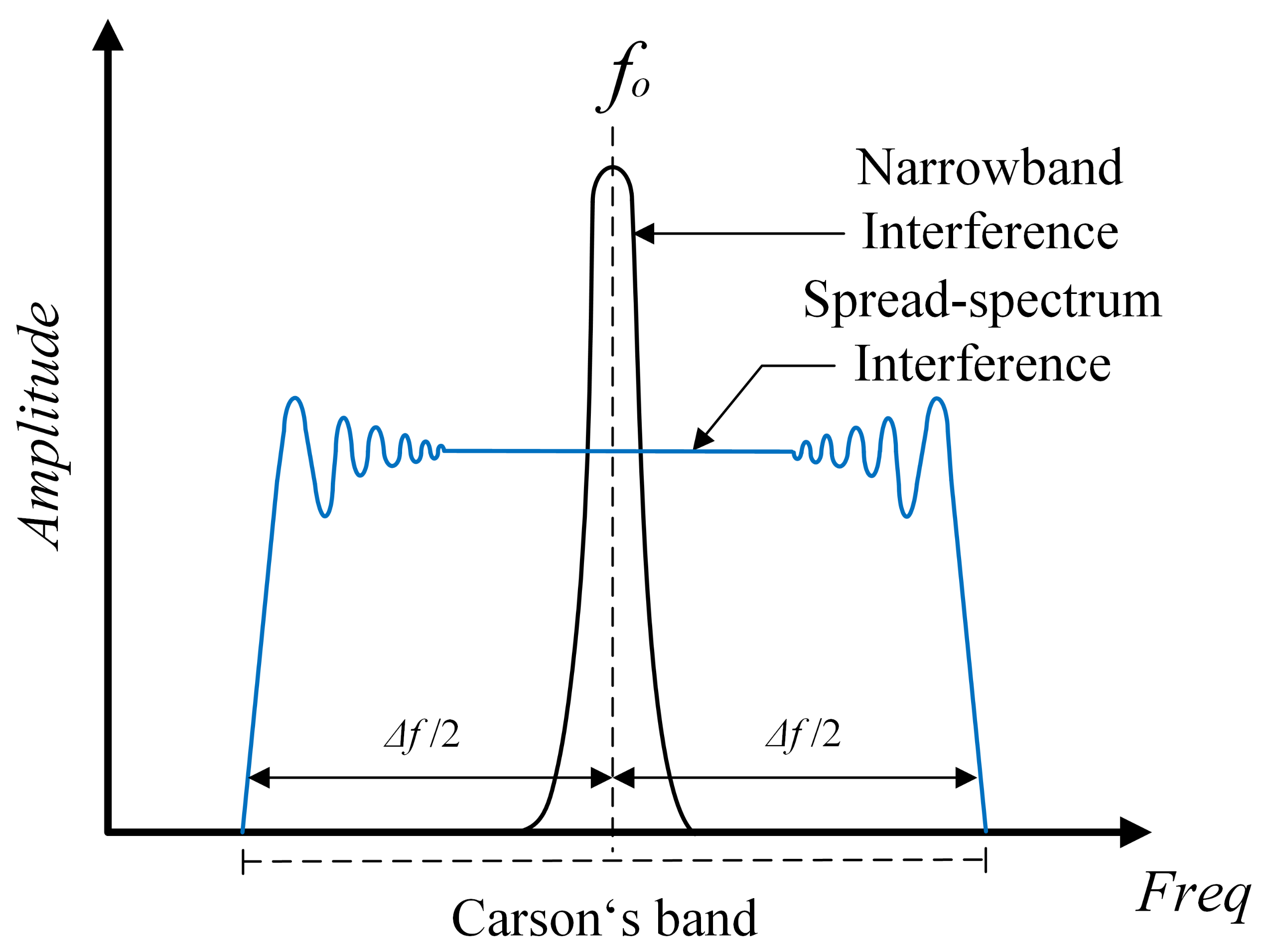
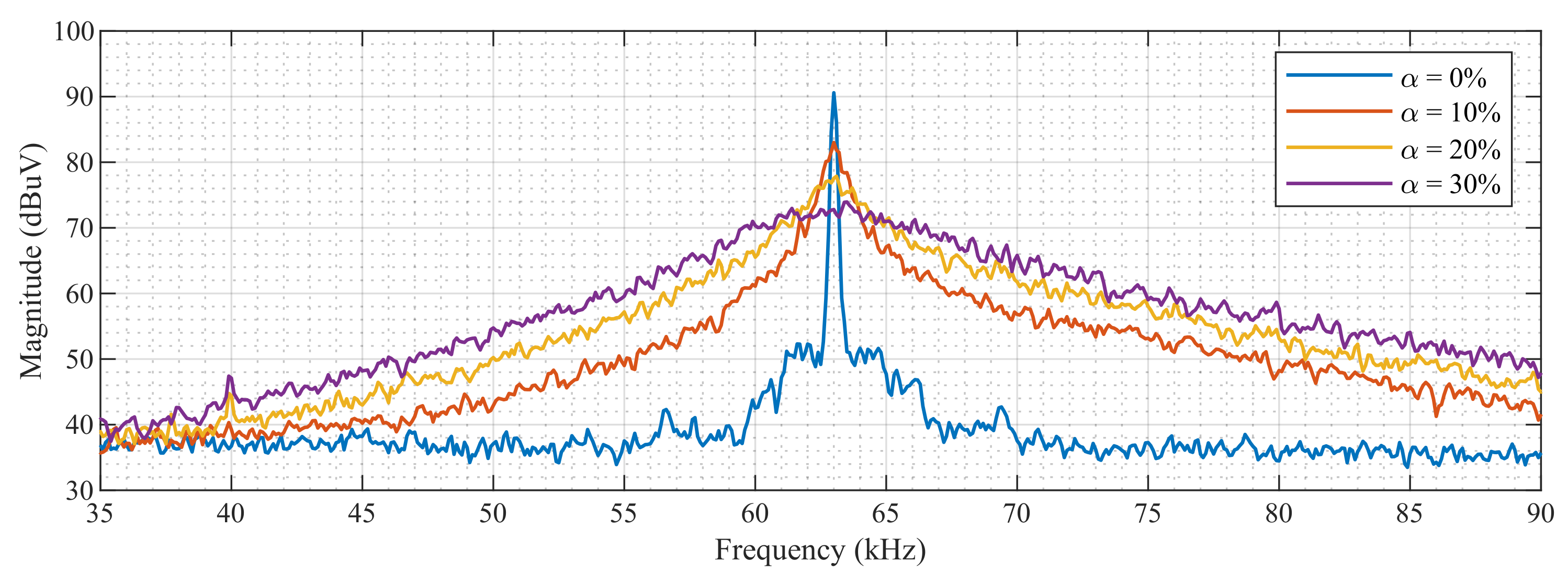
2. Spread-Spectrum Modulation

In the standard PWM with the programmed switching frequency, the signal is generated using a timer in any digital controller, which compares the reference values for duty cycle and frequency to the constant carrier frequency generated by the timer. However, most of the spread-spectrum modulation techniques use frequency modulation of the reference timing signal [27], and this approach of SSM is named random carrier frequency modulation with a fixed duty cycle (RCFMFD). Other types of SSM techniques depend on changing the duty cycle without changing the frequency, such as random carrier frequency modulation with a variable duty cycle (RCFMVD), which, on average, gives the same response as for the first case [28,29].In this paper, we utilize the RCFMFD as an SSM technique for our converter.
In the same framework, the switching signal from the conventional pulse width modulation(PWM) could be represented in terms of its Fourier series expansion as:
S t = k = A k e j 2 π k f 0 t
where k is the harmonic order, A k is the amplitude of the k-th harmonic and f 0 is the fundamental frequency of the switching signal. By contrast, when using the RCFMFD, the switching signal can be expressed in terms of its Fourier series as:
S s s t = k = A k e j 2 π k f 0 t + j 2 π k Δ f t ε τ d τ
Δ f = α f 0
where Δ f is the frequency deviation around the main switching frequency f 0 and α is the spreading factor used to set the required frequency bandwidth, i.e., the Carson bandwidth of the switching signal [ f 0 Δ f /2, f 0 + Δ f /2], as shown in Figure 1. The value of the spreading factor α could vary in practice from 0% to 30%; the increase of the α value increases signal bandwidth and decreases its spectral amplitude. ξ ( τ ) is a driving signal operated with variable amplitude varying with the time; the function of the driving signal ξ ( τ ) could be sinusoidal, triangular, or a random pulse amplitude modulated (PAM) signal [27]. Considering the driving signal ξ ( τ ) as a random PAM signal, the ξ ( τ ) can be expressed as:
ξ ( τ ) = k δ k g t k T
where δ k is a uniformly distributed pseudo-random number varying between −0.5 and +0.5, and g ( t k T ) is a rectangular function with duration time T.
Consequently, the power spectral density of the EMI of the signal S s s ( t ) will be expressed as [22]:
S E M I f = H f 2 k = 0 A k 2 1 k Δ f · ρ f k f 0 k Δ f
where H ( f ) is the transfer function of the EMI coupling and ρ ( x ) is the amplitude probability density function of the spread function.

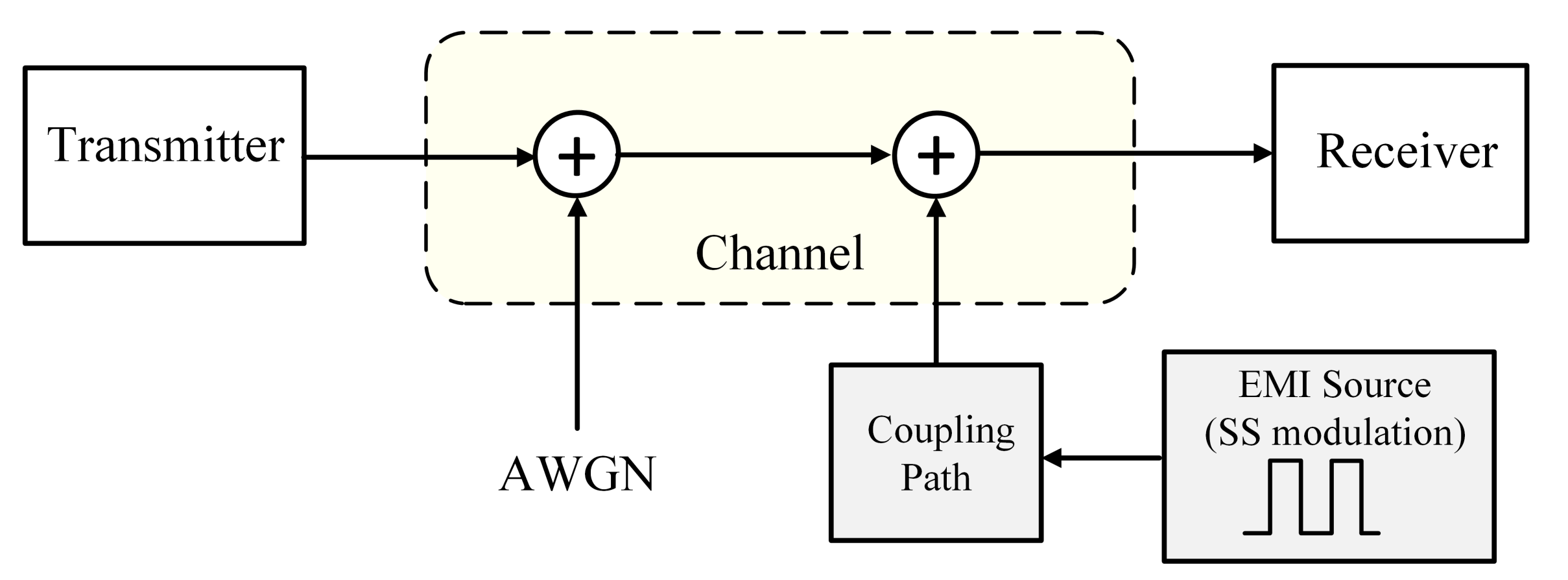
3. The G3-PLC Channel Modeling

After evaluating the source of the EMI, the victim, i.e., the G3-PLC system, is considered. The G3-PLC works by modulating the carrier signal and adding it to the main power signal. The data can be modulated by different digital modulation schemes, such as M-array phase shift keying (M-PSK) or quadrature amplitude modulation (M-QAM). In addition, the data are modulated through orthogonal frequency division multiplexing (OFDM), in which a serial data stream is split into several parallel slower data streams that are modulated around orthogonal sub-carriers [30]. The parameters of the G3-PLC OFDM signal are stated in Table 1. Figure 2 shows the PLC system block diagram in the presence of EMI disturbance.
Based on the EN 50065 standard, the highest limit for intentional emissions generated by mains PLC communicating equipment is 120 dBuV, and the non-intentional emissions on the PLC channel should be below the maximum intentional power by 20–30 dB to allow reliable PLC communication [31].
The PLC signal propagates through copper wires, so the signal may attenuate with the increase in the length of the line, in addition to the presence of the background white noise and the periodical impulsive noise that interferes with the OFDM symbol. In the context of the communication framework, the Shannon–Hartley equation could be used for evaluating the PLC channel capacity to confirm the behavior of the G3-PLC system in the presence of noise [22]. The Shannon–Hartley equation calculates the maximum allowable data transmission rate over a communication channel in the presence of noise, which is close to the rate achieved in practice by communication systems featuring advanced channel coding, like the forward error correction FEC codes adopted in G3-PLC and PRIME [4]. The capacity of the PLC channel is expressed as:
C G 3 = B m i n B m a x l o g 2 1 + S P L C f N f d f
where B m i n and B m a x are the limit frequencies of the PLC bandwidth channel, S P L C ( f ) is the power spectral density of the PLC signal, and N ( f ) is the total noise power spectral density. The total noise of the channel in our case is equal to:
N ( f ) = S 0 + S E M I
where S 0 is the power spectral density of the background noise, modeled as additive white Gaussian noise (AWGN), and S E M I is the EMI power spectral density. Consequently, the capacity loss percentage C L o s s could be calculated as:
C L o s s = C 0 C G 3 C 0 × 100
where C 0 is the calculated capacity of the PLC channel in the EMI-free case, i.e., only including the AWGN ( N ( f ) = S 0 ).

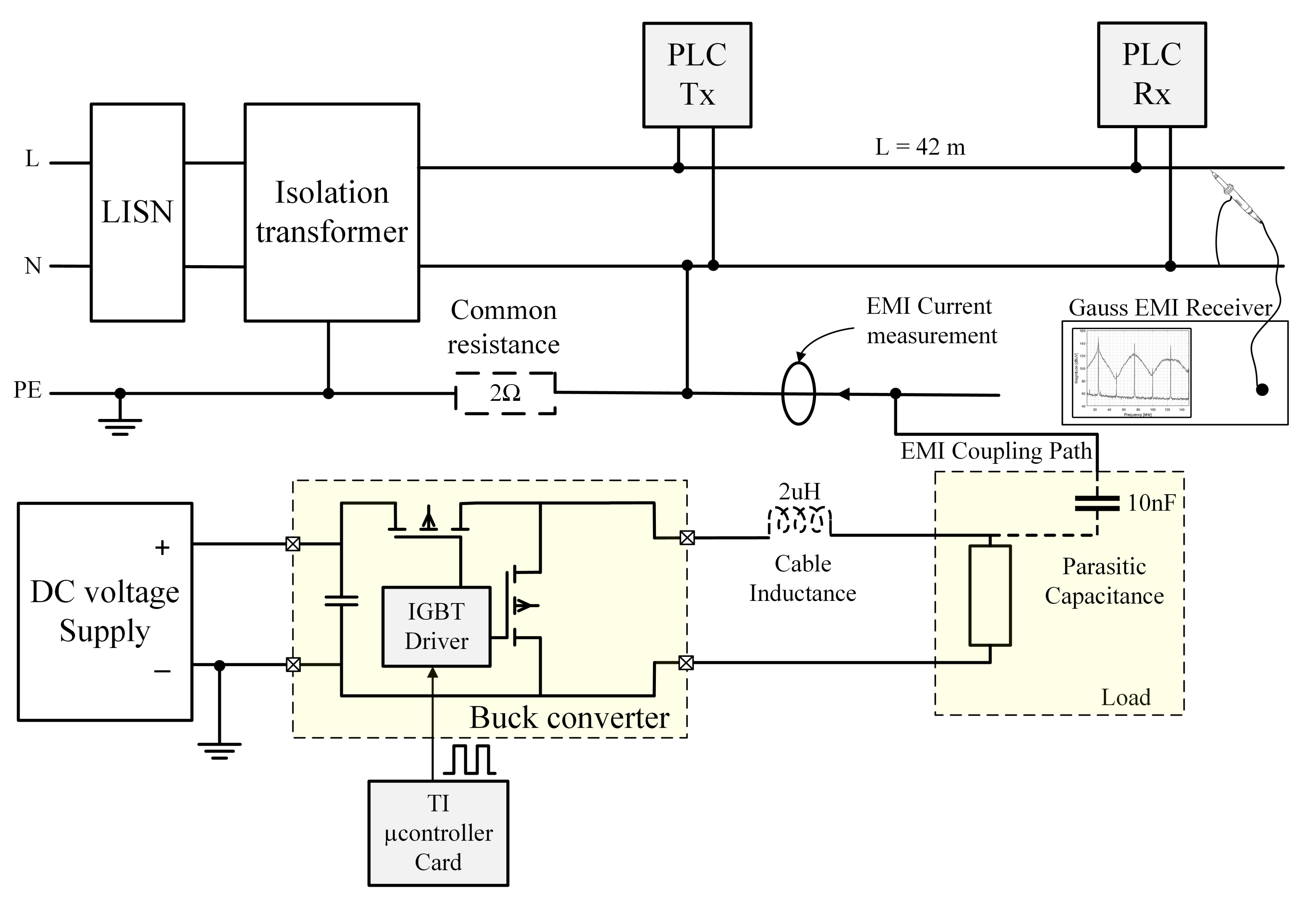
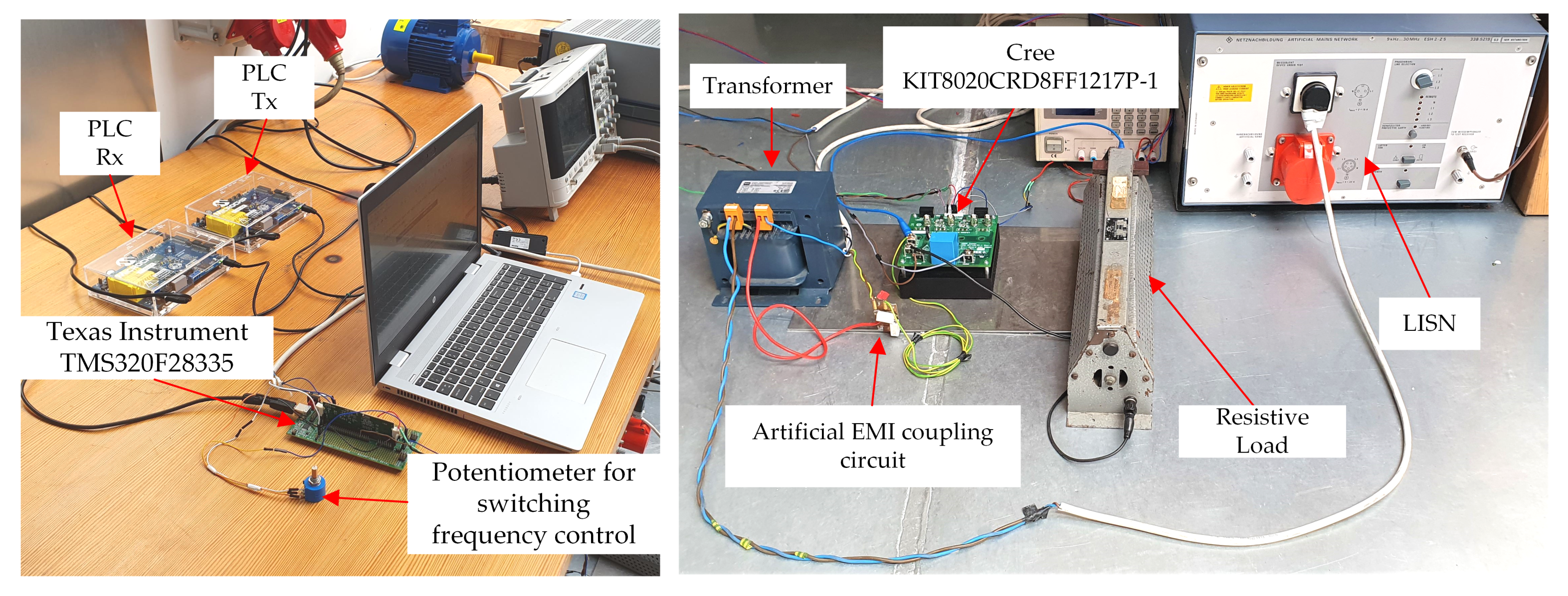
4. Proposed Experimental Setup

The setup in Figure 3 could be applied in the case of residential DC Microgrid systems, in which there are many DC and AC loads connected to the same grid with the presence of solar panels, batteries, and small-scale-power wind turbines [32]. The hardware setup consists of two main circuits. The first circuit is the point-to-point PLC communication circuit. The circuit works using two Microchip ATPL360 PLC modems representing the transmitting and the receiving points as shown in Figure 3; both modems are configured to work based on the CENELEC-A standard frequency range and the G3-PLC mode. In addition, to isolate the outside EMI noise and to make certain of the robustness of the results, an isolating transformer and a line impedance stabilization network (LISN) are connected between the PLC circuit and the grid.
The second circuit is a power circuit of a SiC-based DC buck converter supplying a resistive load as shown in Figure 3. The EMI coupling path is represented by an artificial circuit consisting of a parasitic capacitor connected to the PLC circuit through a common resistance. In the real system, the artificial circuit corresponds to a typical common mode path of interference for high-frequency EMI, the presented inductance can be associated with the inductance of the connected wire, and the presented capacitance corresponds to parasitic couplings to the ground that could exist because of the load enclosures or any other reasons [26].
Usually, there is a type of filter on the output of the buck converter, but the purpose of the circuit is to show the influence of simple first-order oscillatory mode current on the G3-PLC performance. For this reason, the filter was not considered in our setup. The converter used in the setup is built using a CREE SiC MOSFET KIT8020CRD8FF1217P-1 evaluation board and connected to a variable DC supply varying from 10 V to 50 V. The buck converter is controlled by a Texas Instruments TMS320F28335 digital signal processing card. Table 2 shows the electrical data for the converter used in the setup. As the test was implemented using laboratory equipment, the power of the applied load is not too high and a sliding resistor was used to set the required current. The cables used were copper cables of diameter 2 mm2 for both communication and power circuits. Figure 4 shows the setup testbed with both circuits.

5. Experimental Results and Discussion

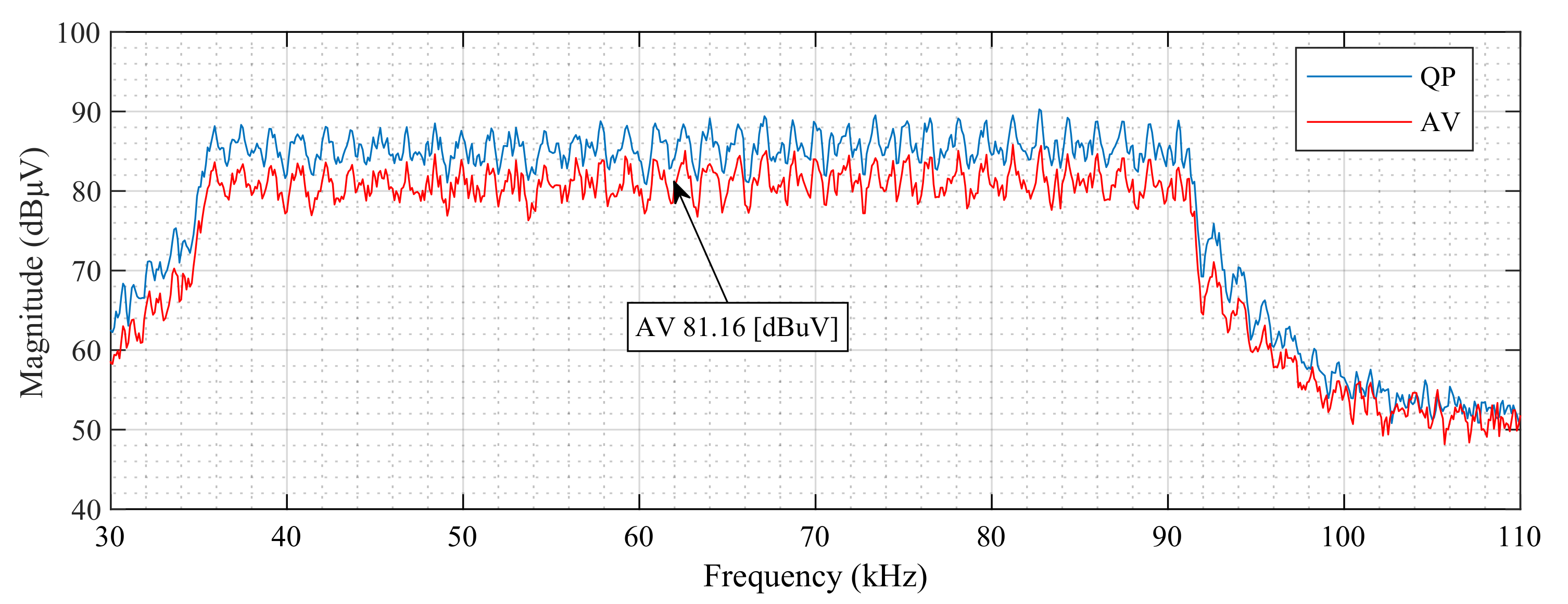
5.1. EMI Spectrum Measurements

The Gauss Instruments company TDMI X6 digital EMI test receiver was used to take the measurements. All the measurements were taken based on CISPR A in the range 9 to 150 kHz, using the average (AV) and quasi-peak (QP) detectors with 200 Hz intermediate frequency bandwidths (IFBWs). As the G3-PLC uses the CENELEC-A standard, the frequency range of the PLC OFDM signal is in the frequency range between 35 and 91 kHz, as shown in the QP and AV detector frequency spectrum in Figure 5 (measured from the PLC side as in Figure 3). The level of the PLC spectrum reaches 81.16 dBuV for the AV detector at the intermediate frequency of 63 kHz of the PLC signal.
Figure 6 shows the parasitic current coming from the coupling path due to the parasitic capacitance existence as shown in Figure 3. The current was measured at a converter switching frequency f 0 equal to 63 kHz in the case of conventional PWM.
To study the influence of the SSM on the PLC signal, several parameters should be set for the control signal. Figure 7 shows the voltage spectrum of the SSM in case of changing the spreading factor from 0% (the conventional PWM) to 30% at a central switching frequency of 63 kHz and converter supply voltage of 50 V, measured from the PLC side using the AV detector and IFBW = 200 Hz. From the EMC standards point of view, the increase in α decreases the EMI noise in the channel. Thus, the SSM signal in the case of α = 30 % should be better than in the case of 10%. In contrast, the results show an opposite conclusion to this hypothesis as we will see in the next subsection.

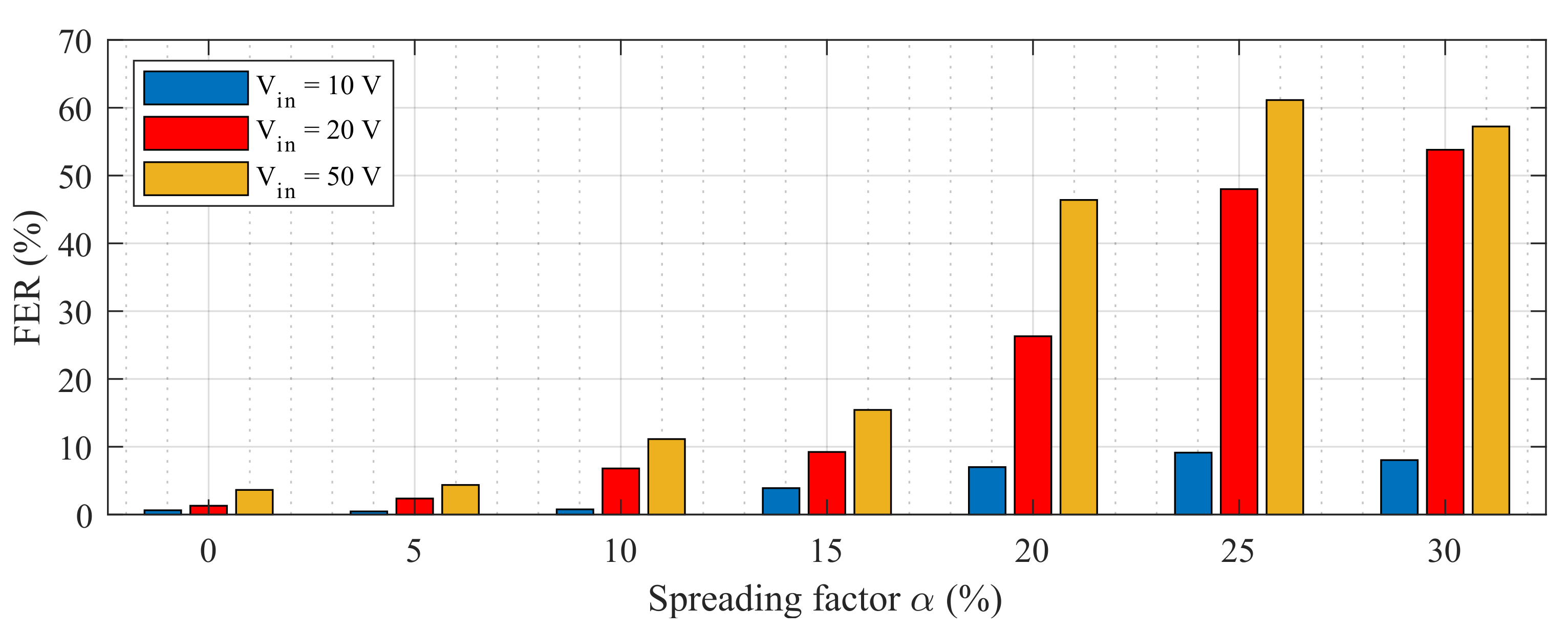
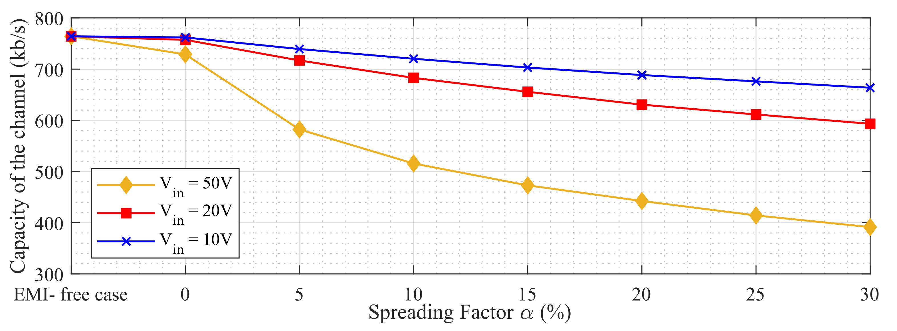
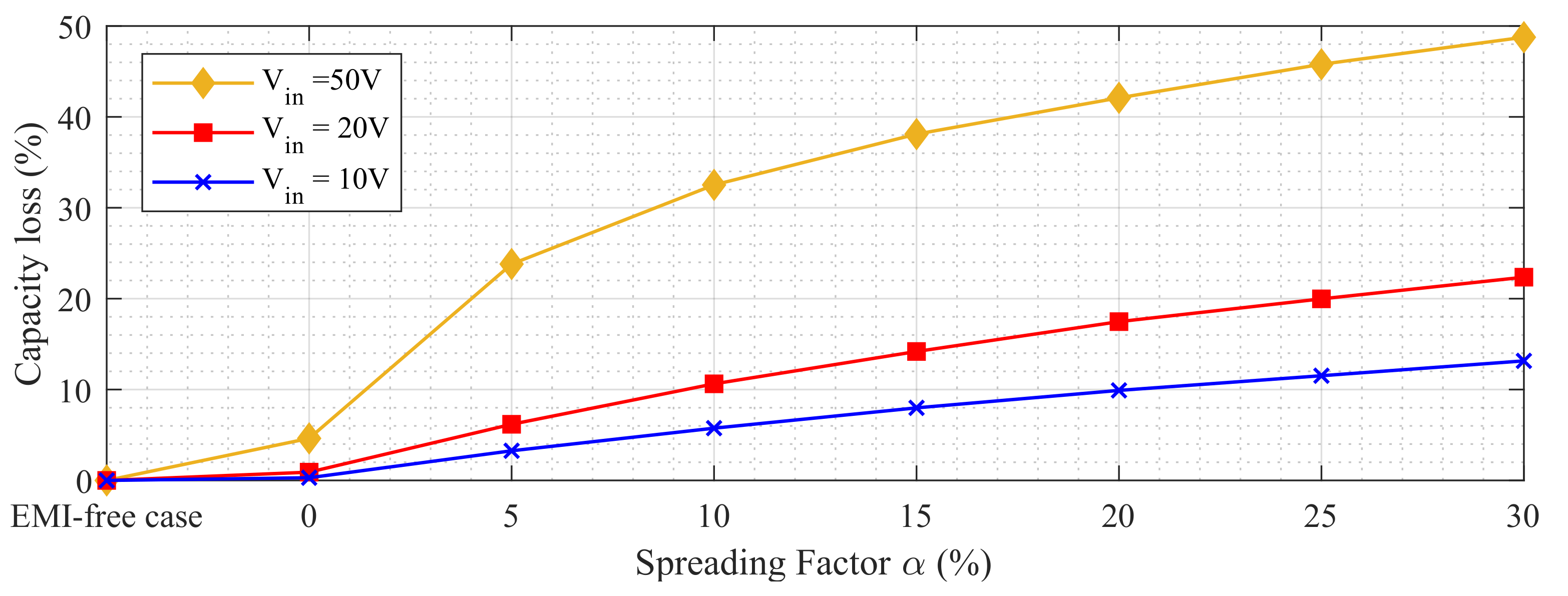
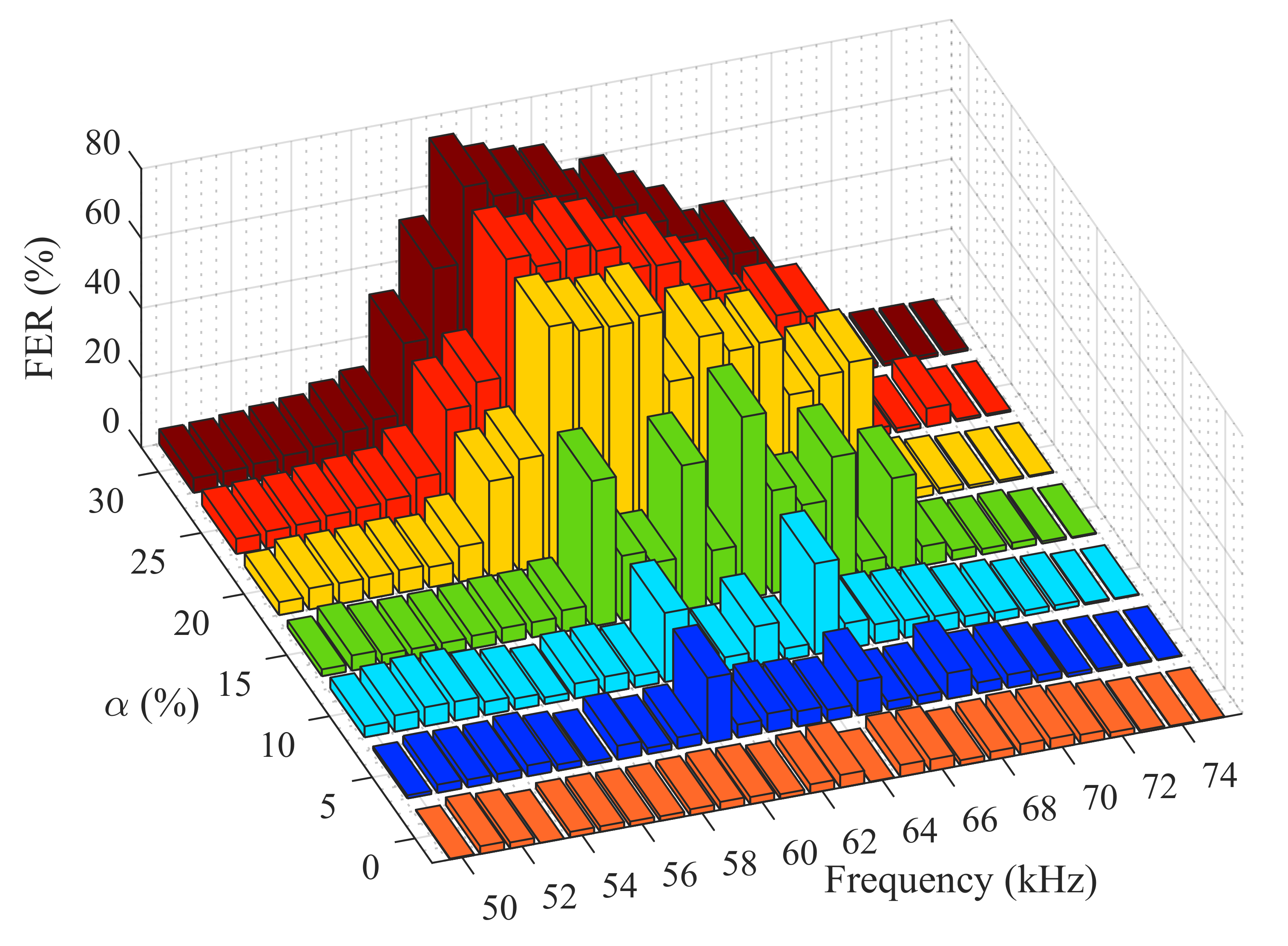
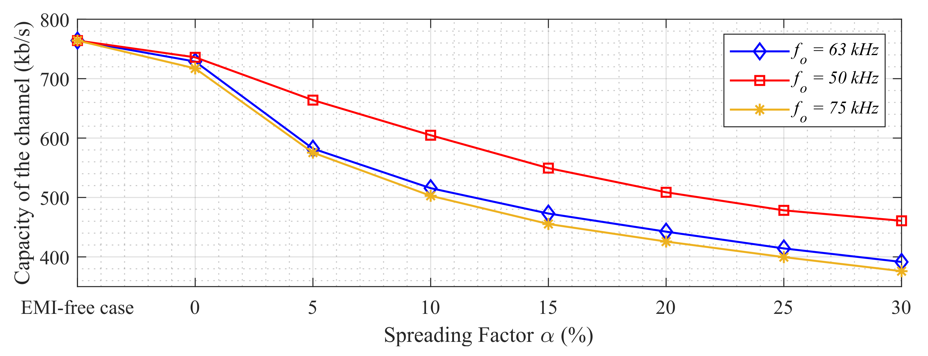
5.2. The PLC Channel Performance in the Presence of EMI

The transmitter modem settings are stated in Table 3. The performance of the PLC channel could be evaluated by the mean of the bit error rate (BER) or the frame error rate (FER); the FER was chosen for the evaluation of the PLC performance as there are many PHY layer procedures (such as equalization, header decoding, and Viterbi decoding) included per frame. In addition, the FER is more connected to the final evaluation of the medium access control (MAC) from the PLC system [33]. The FER percentage represents the ratio between the broken frames to the total sent frames as a percentage, as expressed in Equation (9):
F E R ( % ) = S e n t f r a m e s R e c i e v e d f r a m e s S e n t f r a m e s × 100
In this paper, we considered changing three parameters in the SSM signal. The first is the amplitude of the converter input voltage. The second is Carson’s band Δ f of the SSM signal, which, based on Equation (3), changes by varying of the spreading factor α . The third is the switching frequency f 0 of the converter, to study the effect of SSM with several central switching frequencies working at the same frequency band of the PLC signal.
Figure 8 shows the FER percentage in case of changing the SSM spreading factor at a central switching frequency of 63 kHz, in three operating input voltage cases:10, 20, and 50 V. Obviously, the increase in the amplitude of the input voltage will increase the FER in the PLC channel as shown clearly in the figure. However, the decrease in the amplitude provided by the SSM delivers more problems to the communication signal. The FER reaches its maximum value at a spreading factor of 25% and saturate on 30% in all three cases of input voltages.
Figure 9 shows the channel capacity evaluation based on Equation (6) in all cases of input voltages. It seems clear that the channel capacity is decreased with the increase in the spreading factor of the signal, and the capacity loss in the channel increases with the increase in the spreading factor as shown in Figure 10. The channel capacity calculation confirms the behavior of the FER of the PLC channel with the spreading factor of the SSM, knowing that the channel capacity represents the maximum allowable data that can be transmitted through the communication channel (the maximum bit rate for the G3-PLC is 33 kbit / s ). Consequently, those results show an opposite hypothesis to that used in the EMC standards.
Figure 11 shows the FER percentage in the presence of EMI in the case of operating SSM with different central switching frequencies at a constant input voltage of 50 V. The results show that at any value of SSM of central frequency ranging from 50 to 75 kHz, the FER increases with the increase in the spreading factor α from 0% to 30%. In addition, the highest values of FER appear around the intermediate frequency of the communication bandwidth, between 56 and 69 kHz.
The variation in the central frequency of the SSM signal creates two situations in terms of EMI noise: fully overlapped with the intentional bandwidth of the PLC signal or partially overlapped with the intentional bandwidth of the PLC signal. The first case appear when the bandwidth of the SSM is smaller than the bandwidth of the communication signal, in addition, the value of the SSM central switching frequency is near to the intermediate frequency of the PLC signal (which is 63 kHz in the case of the G3-PLC). However, the second case appears when part of the signal is out of the PLC bandwidth, as the switching frequency starts to go away from the intermediate frequency of the PLC bandwidth.
Figure 12 shows the channel capacity calculation for the G3-PLC channel in the case of SSM utilizing three central switching frequencies; the first one is equal to the intermediate frequency of the PLC (63 kHz), the second is less than this by 13 kHz (50 kHz) and the third is greater than this by 12 kHz (75 kHz). It is noted that that the channel capacity in the case of the frequency equal to 50 kHz is less than that in the case of 63 kHz. However, in the case of 75 kHz, the channel capacity values are near that in the case of the intermediate frequency due to the nature of the EMI noise amplitude with the increase in the SSM central switching frequency. In addition, the channel capacity decreases with the same slope in all switching frequency cases as shown in the figure. Figure 13 shows channel capacity loss due to the variation in the spreading factor in the three utilized central switching frequencies.

6. Conclusions

In this paper we have shown the influence of EMI generated from a spread-spectrum-modulated SiC-based buck converter on the G3-PLC communication channel performance in terms of the Shannon–Hartley channel capacity equation. In the literature, researchers have proposed many spread spectrum modulation techniques as a useful tool for EMI mitigation instead of adding a filter to the power converter circuit, and also as a good way to pass the EMC compliance test; however, the results presented in this paper show the opposite hypothesis. At certain circuit parameter conditions, results show that the SSM could deliver more problems to the PLC system, despite the reduced peaks in the EMI spectra measured according to the standard EMC measurement procedures. The FER test was performed and the behavior of the PLC system was confirmed by the channel capacity equation of the G3-PLC in several working scenarios. The first scenario involved changing the EMI amplitude of the SSM signal as well as increasing the SSM spreading band at a certain central frequency of SSM. As a result, the FER percentage increased as the spreading factor of the SSM increased in all tested EMI amplitudes. The second scenario involved changing the central switching frequency of the SSM as well as changing the spreading factor at a constant EMI amplitude; the results show that the highest probability of data transmission errors appeared when the central switching frequency of SSM was equal to or near the intermediate frequency of the PLC bandwidth. As the central frequency of the SSM signal moved away from the intermediate frequency of the PLC bandwidth, the SSM signal appeared to be partially overlapped with the communication bandwidth, leading to the increase in channel capacity data transmission capability, as only part of the SSM signal interferes with the communication bandwidth. The spreading of the modulation signal could be a good approach to pass the EMC compliance tests; however, this could also create more problems for the G3-PLC system.

Author Contributions

Conceptualization, W.E.S., P.L. and R.S.; methodology, W.E.S. and P.C.; software, W.E.S. and P.C.; validation, W.E.S., P.L., R.S., N.M. and P.C.; formal analysis, W.E.S., R.S. and D.W.P.T.; investigation, W.E.S., P.L. and P.C.; resources, R.S.; data curation, W.E.S.; writing—original draft preparation, W.E.S.; writing—review and editing, P.C. and N.M.; visualization, W.E.S.; supervision, W.E.S. and D.W.P.T.; project administration, R.S.; funding acquisition, R.S. All authors have read and agreed to the published version of the manuscript.

Funding

This paper is part of two projects that have received funding from the European Union’s Horizon 2020 research and innovation program under the Marie Sklodowska-Curie grant agreement No. 812391-SCENT and No. 812753-ETOPIA.

Conflicts of Interest

The authors declare no conflict of interest.

References

  1. Wibisono, M.A.; Moonen, N.; Leferink, F. Interference of LED Lamps on Narrowband Power Line Communication. In Proceedings of the 2020 IEEE International Symposium on Electromagnetic Compatibility and Signal/Power Integrity (EM-CSI), Reno, NV, USA, 28 July–28 August 2020; pp. 219–221. [Google Scholar]
  2. Cano, C.; Pittolo, A.; Malone, D.; Lampe, L.; Tonello, A.M.; Dabak, A. State-of-the-art in Power Line Communications: From the Applications to the Medium. IEEE J. Sel. Areas Commun. 2016, 34, 1935–1952. [Google Scholar] [CrossRef] [Green Version]
  3. Hoch, M. Comparison of PLC G3 and PRIME. In Proceedings of the 2011 IEEE International Symposium on Power Line Communications and Its Applications, Udine, Italy, 3–6 April 2011; pp. 165–169. [Google Scholar]
  4. Matanza, J.; Alexandres, S.; Rodriguez-Morcillo, C. Performance evaluation of two narrowband PLC systems: PRIME and G3. Comput. Stand. Interfaces 2013, 36, 1. [Google Scholar] [CrossRef]
  5. Rönnberg, S.K.; Bollen, M.H.; Amaris, H.; Chang, G.W.; Gu, I.Y.; Kocewiak, Ł.H.; Meyer, J.; Olofsson, M.; Ribeiro, P.F.; Desmet, J. On waveform distortion in the frequency range of 2 kHz–150 kHz—Review and research challenges. Electr. Power Syst. Res. 2017, 150, 1–10. [Google Scholar] [CrossRef]
  6. Meyer, J.; Khokhlov, V.; Klatt, M.; Blum, J.; Waniek, C.; Wohlfahrt, T.; Myrzik, J. Overview and Classification of Interferences in the Frequency Range 2–150 kHz (Supraharmonics). In Proceedings of the International Symposium on Power Electronics, Electrical Drives, Automation and Motion (SPEEDAM 2018), Amalfi, Italy, 20–22 June 2018; pp. 165–170. [Google Scholar]
  7. Vechalapu, K.; Bhattacharya, S.; Brunt, E.V.; Ryu, S.H.; Grider, D.; Palmour, J.W. Comparative Evaluation of 15-kV SiC MOSFET and 15-kV SiC IGBT for Medium-Voltage Converter under the Same dv/dt Conditions. IEEE J. Emerg. Sel. Top. Power Electron. 2017, 5, 469–489. [Google Scholar] [CrossRef]
  8. Ji, S.; Zhang, Z.; Wang, F. Overview of high voltage sic power semiconductor devices: Development and application. CES Trans. Electr. Mach. Syst. 2020, 1, 254–264. [Google Scholar] [CrossRef]
  9. Zhang, L.; Yuan, X.; Wu, X.; Shi, C.; Zhang, J.; Zhang, Y. Performance Evaluation of High-Power SiC MOSFET Modules in Comparison to Si IGBT Modules. IEEE Trans. Power Electron. 2019, 34, 1181–1196. [Google Scholar] [CrossRef]
  10. Li, X.; Li, X.; Yang, L.; Huang, A.Q.; Liu, P.; Deng, X.; Zhang, B. Switching Loss Model of SiC MOSFET Promoting High Frequency Applications. In Proceedings of the International Symposium on Power Semiconductor Devices and ICs, Shanghai, China, 19–23 May 2019; pp. 231–234. [Google Scholar]
  11. Xie, Y.; Chen, C.; Huang, Z.; Liu, T.; Kang, Y.; Luo, F. High Frequency Conducted EMI Investigation on Packaging and Modulation for a SiC-Based High Frequency Converter. IEEE J. Emerg. Sel. Top. Power Electron. 2019, 7, 1789–1804. [Google Scholar] [CrossRef]
  12. El Sayed, W.; Loschi, H.; Lok, C.L.; Lezynski, P.; Smolenski, R. Prospective Analysis of the effect of Silicon based and Silicon-Carbide based Converter on G3 Power Line Communication. In Proceedings of the 2020 International Symposium on Electromagnetic Compatibility—EMC EUROPE, Rome, Italy, 23–25 September 2020. [Google Scholar]
  13. Smolenski, R.; Bojarski, J.; Kempski, A.; Lezynski, P. Time-Domain-Based Assessment of Data Transmission Error Probability in Smart Grids With Electromagnetic Interference. IEEE Trans. Ind. Electron. 2014, 61, 1882–1890. [Google Scholar] [CrossRef]
  14. Chen, H.; Wang, T. Estimation of Common-Mode Current Coupled to the Communication Cable in a Motor Drive System. IEEE Trans. Electromagn. Compat. 2018, 60, 1777–1785. [Google Scholar] [CrossRef]
  15. Li, K.; Xie, Y.; Zhang, F.; Chen, Y. Statistical Inference of Serial Communication Errors Caused by Repetitive Electromagnetic Disturbances. IEEE Trans. Electromagn. Compat. 2019, 62, 1160–1168. [Google Scholar] [CrossRef]
  16. Adrian, V.; Chang, J.S.; Gwee, B.; Tedjaseputro, S. Spectral Analysis of Randomized Switching Frequency Modulation Scheme with a Triangular Distribution for DC-DC Converters. In Proceedings of the 2009 International Conference on Computing, Engineering and Information, Fullerton, CA, USA, 2–4 April 2009. [Google Scholar]
  17. Cui, K.; Adrian, V.; Sun, Y.; Gwee, B.; Chang, J.S. A Low-Harmonics Low-Noise Randomized Modulation Scheme for Multi-Phase DC-DC Converters. In Proceedings of the 15th IEEE International New Circuits and Systems Conference (NEWCAS), Strasbourg, France, 25–28 June 2017; pp. 165–168. [Google Scholar]
  18. Loschi, H.; Lezynski, P.; Smolenski, R.; Nascimento, D.; Sleszynski, W. FPGA-Based System for Electromagnetic Interference Evaluation in Random Modulated DC/DC Converters. Energies 2020, 13, 2389. [Google Scholar] [CrossRef]
  19. Johnson, S.; Zane, R. Custom spectral shaping for EMI reduction in high-frequency inverters and ballasts. IEEE Trans. Power Electron. 2005, 20, 1499–1505. [Google Scholar] [CrossRef]
  20. Kim, M.W.; Kim, D.W.; Koo, B.S.; Kim, Y.B.; Choi, O.S.; Kim, N.D. Chip level techniques for EMI reduction in LCD panels. In Proceedings of the 20th International Zurich Symposium on Electromagnetic Compatibility, EMC Zurich 2009, Zurich, Switzerland, 12–16 January 2009; Volume 2, pp. 441–444. [Google Scholar]
  21. Ko, J.; Lee, S.; Kim, D.; Kim, K.; Chang, K.E. Spread spectrum clock generator for reducing ElectroMagnetic Interference (EMI) noise in LCD driver IC. In Proceedings of the 2007 50th Midwest Symposium on Circuits and Systems, Montreal, QC, Canada, 5–8 August 2007; pp. 1106–1109. [Google Scholar]
  22. Musolino, F.; Crovetti, P.S. Interference of Spread-Spectrum Modulated Disturbances on Digital Communication Channels. IEEE Access 2019, 7, 158969–158980. [Google Scholar] [CrossRef]
  23. Crovetti, P.S.; Musolino, F. Interference of Spread-Spectrum EMI and Digital Data Links under Narrowband Resonant Coupling. Electronics 2020, 9, 60. [Google Scholar] [CrossRef] [Green Version]
  24. Musolino, F.; Crovetti, P.S. Interference of Spread-Spectrum Switching-Mode Power Converters and Low-Frequency Digital Lines. In Proceedings of the 2018 IEEE International Symposium on Circuits and Systems (ISCAS), Florence, Italy, 27–30 May 2018; p. 5. [Google Scholar]
  25. Bojarski, J.; Smolenski, R.; Lezynski, P.; Sadowski, Z. Diophantine equation based model of data transmission errors caused by interference generated by DC-DC converters with deterministic modulation. Bull. Pol. Acad. Sci. Tech. Sci. 2016, 64, 575–580. [Google Scholar] [CrossRef]
  26. Lezynski, P.; Smolenski, R.; Loschi, H.; Thomas, D.; Moonen, N. A novel method for EMI evaluation in random modulated power electronic converters. Measurement 2020, 151, 107098. [Google Scholar] [CrossRef]
  27. Pareschi, F.; Rovatti, R.; Setti, G. EMI reduction via spread spectrum in DC/DC converters: State of the art, optimization, and tradeoffs. IEEE Access 2015, 3, 2857–2874. [Google Scholar] [CrossRef]
  28. Mihalic, F.; Bezjak, T.; Milanovic, M. Random modulated boost converter with improved harmonic spectrum. IEEE Int. Symp. Ind. Electron. 1997, 2, 268–273. [Google Scholar]
  29. Mathe, L.; Lungeanu, F.; Sera, D.; Rasmussen, P.O.; Pedersen, J.K. Spread Spectrum Modulation by Using Pwm, Asymmetric-carrier Random. IEEE Trans. Ind. Electron. 2012, 59, 3710–3718. [Google Scholar] [CrossRef]
  30. Schwarz, M.; Gronwald, F. EMI analysis of a generic power line communication OFDM data link. In Proceedings of the EMC Europe 2011 York—10th International Symposium on Electromagnetic Compatibility, York, UK, 26–30 September 2011; pp. 625–628. [Google Scholar]
  31. Fernandez, I. Characterization of non-intentional emissions from distributed energy resources up to 500 kHz: A case study in Spain. Int. J. Electr. Power Energy Syst. 2019, 105, 549–563. [Google Scholar] [CrossRef]
  32. Choi, H.J.; Jung, J.H. Enhanced Power Line Communication Strategy for DC Microgrids Using Switching Frequency Modulation of Power Converters. IEEE Trans. Power Electron. 2017, 32, 4140–4144. [Google Scholar] [CrossRef]
  33. Llano, A.; Angulo, I.; Angueira, P.; Arzuaga, T.; De la Vega, D. Analysis of the Channel Influence to Power Line Communications Based on ITU-T G.9904 (PRIME). Energies 2016, 9, 39. [Google Scholar] [CrossRef] [Green Version]
Figure 1. Conventional PWM vs. SSM techniques.
Electronics 10 01416 g001
Figure 2. Block diagram representing the G3-PLC channel with the EMI noise.
Electronics 10 01416 g002
Figure 3. Connection diagram of the system.
Electronics 10 01416 g003
Figure 4. Setup testbed.
Electronics 10 01416 g004
Figure 5. The spectrum of the G3 signal for PLC.
Electronics 10 01416 g005
Figure 6. The common mode current due to the parasitic coupling path.
Electronics 10 01416 g006
Figure 7. The spectrum of SSM EMI measured from the PLC side.
Electronics 10 01416 g007
Figure 8. The PLC channel FER evaluation in the case of SSM EMI with several amplitudes and spreading factors α .
Electronics 10 01416 g008
Figure 9. The PLC channel capacity in the case of several values of spreading factor with the change in input voltage amplitude of the converter.
Electronics 10 01416 g009
Figure 10. The PLC channel capacity loss in the case of several values of spreading factor with the change in input voltage amplitude of the converter.
Electronics 10 01416 g010
Figure 11. The PLC channel FER evaluation in the case of SSM EMI with several switching frequencies and spreading factors α .
Electronics 10 01416 g011
Figure 12. The PLC channel capacity in the case of several values of spreading factor with the change in the central switching frequency of SSM.
Electronics 10 01416 g012
Figure 13. The PLC channel capacity loss in the case of several values of spreading factor with the change in the central switching frequency of SSM.
Electronics 10 01416 g013
Table 1. G3-PLC specifications.
SpecificationG3-PLC
Frequency Range35–91 kHz
Sampling Frequency fs400 kHz
FFT size256
Length of Cyclic Prefix30
Sub-Carrier Spacing1.5625 kHz
No. of Carriers Used36
Max Data Rate33.4 kbps
ModulationDBPSK, DQPSK, and D8PSK
Table 2. Buck converter electrical data.
ItemValue
Transistor typeC2M0080120D
Input voltage50 V
Input current0.6 A
Output voltage25 V
Output current1.2 A
Switching main frequencyVaries from 50 to 75 kHz
Duty cycle50%
Table 3. PLC communication assumptions.
Type of PLC communication standardG3-PLC
Data size65 bytes
Physical layerOFDM
ModulationDBPSK-DQPSK-D8PSK
Total sent frames3000
The time between each packet100 ms
The mediumSingle-phase cable of length 42 m
Publisher’s Note: MDPI stays neutral with regard to jurisdictional claims in published maps and institutional affiliations.

