Nano-Structured Optical Fibers Made of Glass-Ceramics, and Phase Separated and Metallic Particle-Containing Glasses


 ,
,  and
and 
Abstract
1. Introduction
2. Potential Benefits of PCGs
2.1. Glass-Ceramics
2.2. Phase-Separated Glasses
2.3. Metallic Nanoparticles in Glasses
3. Preparation of Particle-Containing Glasses
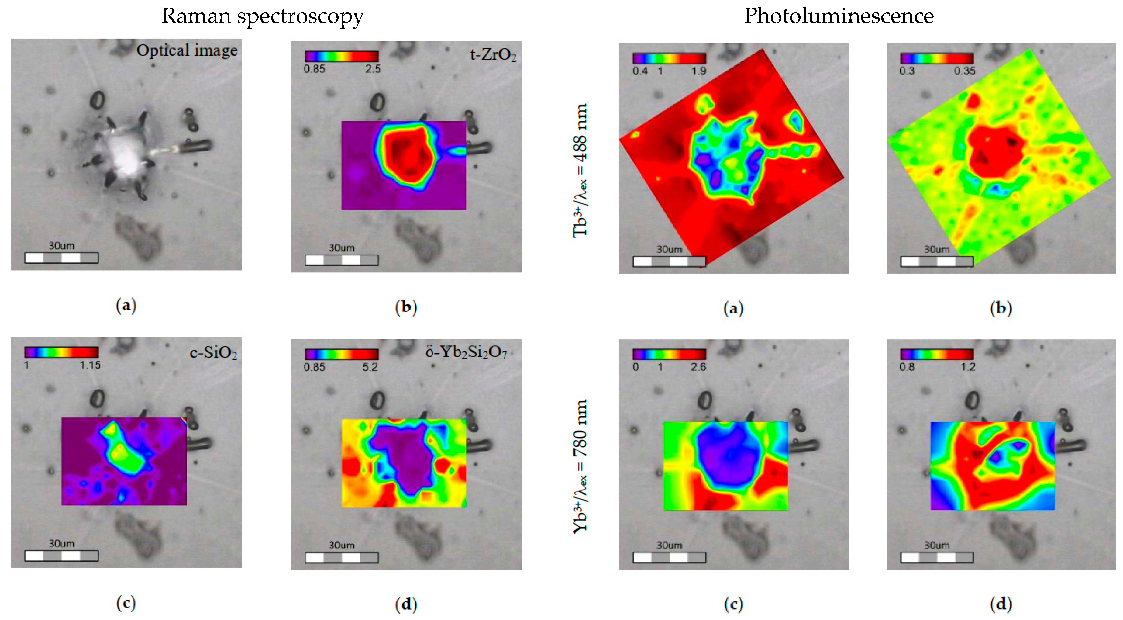
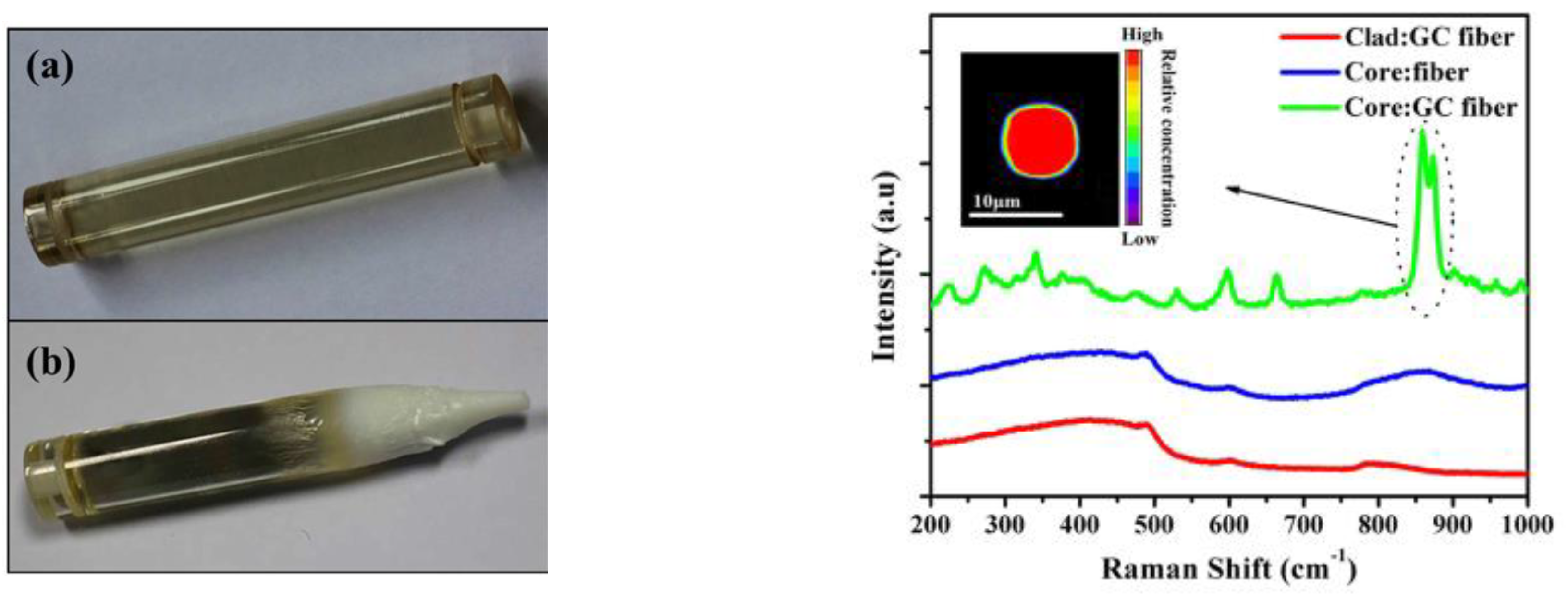
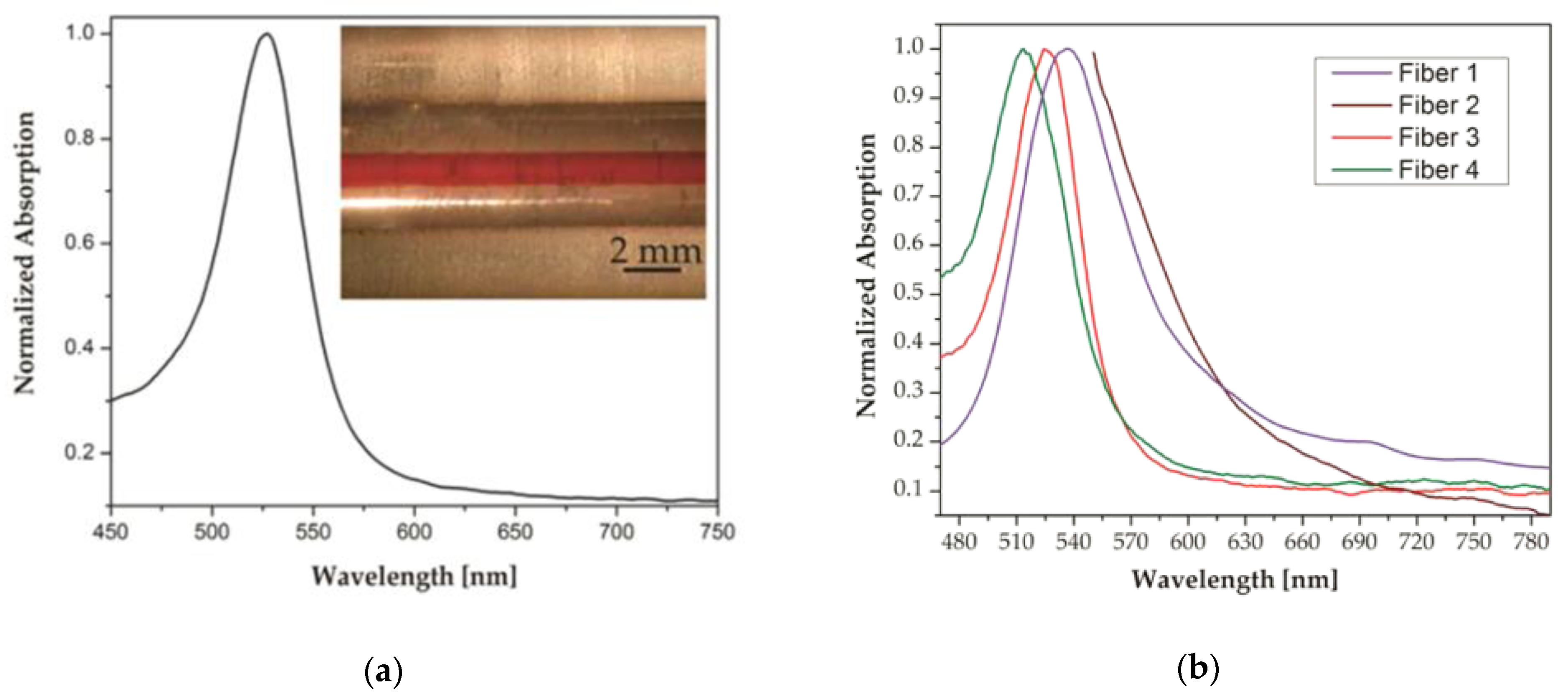
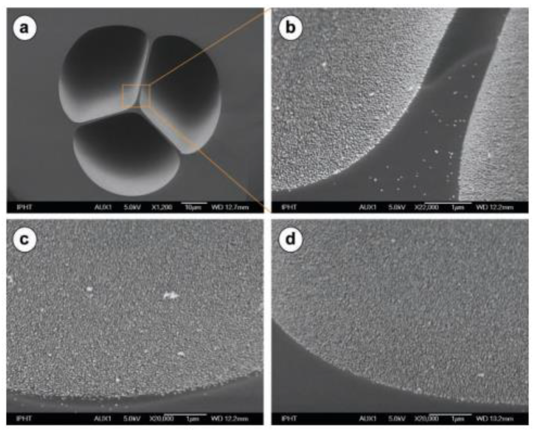
4. Characterization of PCGs
5. Control of PCGs Transparency
6. Fiber Fabrication Methods
7. Advances in the Fabrication of PCG Fibers
7.1. Glass-Ceramics Fibers
7.2. Phase-Separated Fibers
7.3. MeNP-Containing Fibers
8. Conclusions
Author Contributions
Funding
Conflicts of Interest
References
- Stookey, S.D. Method of Making Ceramics and Product Thereof. U.S. Patent 2920971, 12 January 1960. [Google Scholar]
- Deubener, J.; Allix, M.; Davis, M.J.; Duran, A.; Höche, T.; Honma, T.; Komatsu, T.; Krüger, S.; Mitra, I.; Müller, R.; et al. Updated definition of glass-ceramics. J. Non-Cryst. Solids 2018, 501, 3–10. [Google Scholar] [CrossRef]
- Beall, G.H.; Duke, D.A. Transparent glass-ceramics. J. Mater. Sci. 1969, 4, 340–352. [Google Scholar] [CrossRef]
- Herczog, A. Phase Distribution and Transparency in Glass-Ceramics Based on a Study of the Sodium Niobate-Silica System. J. Am. Ceram. Soc. 1990, 73, 2743–2746. [Google Scholar] [CrossRef]
- Kokubo, T.; Tashiro, M. Dielectric properties of fine-grained PbTiO3 crystals precipitated in a glass. J. Non-Cryst. Solids 1974, 13, 328–340. [Google Scholar] [CrossRef]
- Layton, M.M.; Smith, J.W. Pyroelectric Response in Transparent Ferroelectric Glass-Ceramics. J. Am. Ceram. Soc. 1975, 58, 435–437. [Google Scholar] [CrossRef]
- Fang, Z.; Zheng, S.; Peng, W.; Zhang, H.; Ma, Z.; Zhou, S.; Chen, D.; Qiu, J. Fabrication and Characterization of Glass-Ceramic Fiber-Containing Cr3+-Doped ZnAl2O4 Nanocrystals. J. Am. Ceram. Soc. 2015, 98, 2772–2775. [Google Scholar] [CrossRef]
- Auzel, F.; Pecile, D.; Morin, D. Rare Earth Doped Vitroceramics: New, Efficient, Blue and Green Emitting Materials for Infrared Up-Conversion. J. Electrochem. Soc. 1975, 122, 101–107. [Google Scholar] [CrossRef]
- Wang, Y.; Ohwaki, J. New transparent vitroceramics codoped with Er3+ and Yb3+ for efficient frequency upconversion. Appl. Phys. Lett. 1993, 63, 3268–3270. [Google Scholar] [CrossRef]
- Creig, J.W. Immiscibility in silicate melts; Part II. Am. J. Sci. 1927, 13, 133–154. [Google Scholar] [CrossRef]
- Turner, W.E.S.; Winks, F. The influence of boric oxide on the properties of chemical and heat-resisting glasses. Part II. The resistance to chemical reagents. J. Soc. Glass Technol. 1926, 10, 102–113. [Google Scholar]
- Beall, G.H.; Pinckney, L.R. Nanophase Glass-Ceramics. J. Am. Ceram. Soc. 1999, 82, 5–16. [Google Scholar] [CrossRef]
- Chen, D.; Wan, Z.; Zhou, Y.; Huang, P.; Zhong, J.; Ding, M.; Xiang, W.; Liang, X.; Ji, Z. Bulk glass ceramics containing Yb3+/Er3+: β-NaGdF4 nanocrystals: Phase-separation-controlled crystallization, optical spectroscopy and upconverted temperature sensing behavior. J. Alloys. Compd. 2015, 638, 21–28. [Google Scholar] [CrossRef]
- Höland, W.; Rheinberger, V.; Schweiger, M. Control of nucleation in glass ceramics. Philos. Trans. R. Soc. Lond. A 2003, 361, 575–589. [Google Scholar] [CrossRef]
- Minot, M.J. Single-layer, gradient refractive index antireflection films effective from 0.35 to 2.5 µ. J. Opt. Soc. Am. 1976, 66, 515–519. [Google Scholar] [CrossRef]
- Inoue, S.; Makishima, A.; Inoue, H.; Soga, K.; Konishi, T.; Asano, T. An approach to new glasses through phase separation. J. Non-Cryst. Solids 1999, 247, 1–8. [Google Scholar] [CrossRef]
- Chiang, C.-C.; Shyu, J.-J. Compositional Dependence of Phase Separation and Photoluminescence in Er-Doped Alkaline Borosilicate Glasses. J. Am. Ceram. Soc. 2009, 92, 2590–2597. [Google Scholar] [CrossRef]
- Fang, Z.; Chen, Z.; Peng, W.; Shao, C.; Zheng, S.; Hu, L.; Qiu, J.; Guan, B.-O. Phase-Separation Engineering of Glass for Drastic Enhancement of Upconversion Luminescence. Adv. Opt. Mater. 2019, 7, 1801572. [Google Scholar] [CrossRef]
- Drexhage, K.H. Influence of a dielectric interface on fluorescence decay time. J. Lumin. 1970, 1–2, 693–701. [Google Scholar] [CrossRef]
- Da Silva, D.M.; Kassab, L.R.P.; Lüthi, S.R.; de Araújo, C.B.; Gomes, A.S.L.; Bell, M.J.V. Frequency upconversion in Er3+ doped PbO–GeO2 glasses containing metallic nanoparticles. Appl. Phys. Lett. 2007, 90, 081913. [Google Scholar] [CrossRef]
- Hayakawa, T.; Tamil Selvan, S.; Nogami, M. Enhanced fluorescence from Eu3+ owing to surface plasma oscillation of silver particles in glass. J. Non-Cryst. Solids 1999, 259, 16–22. [Google Scholar] [CrossRef]
- Kassab, L.R.P.; de Araújo, C.B.; Kobayashi, R.A.; de Almeida Pinto, R.; da Silva, D.M. Influence of silver nanoparticles in the luminescence efficiency of Pr3+-doped tellurite glasses. J. Appl. Phys. 2007, 102, 103515. [Google Scholar] [CrossRef]
- De Almeida, R.; da Silva, D.M.; Kassab, L.R.P.; de Araújo, C.B. Eu3+ luminescence in tellurite glasses with gold nanostructures. Opt. Commun. 2008, 281, 108–112. [Google Scholar] [CrossRef]
- Awang, A.; Ghoshal, S.K.; Sahar, M.R.; Arifin, R.; Nawaz, F. Non-spherical gold nanoparticles mediated surface plasmon resonance in Er3+ doped zinc–sodium tellurite glasses: Role of heat treatment. J. Lumin. 2014, 149, 138–143. [Google Scholar] [CrossRef]
- Fares, H.; Elhouichet, H.; Gelloz, B.; Férid, M. Surface plasmon resonance induced Er3+ photoluminescence enhancement in tellurite glass. J. Appl. Phys. 2015, 117, 193102. [Google Scholar] [CrossRef]
- Fukushima, M.; Managaki, N.; Fujii, M.; Yanagi, H.; Hayashi, S. Enhancement of 1.54-μm emission from Er-doped sol-gel SiO2 films by Au nanoparticles doping. J. Appl. Phys. 2005, 98, 024316. [Google Scholar] [CrossRef]
- Kassab, L.R.P.; Bomfim, F.A.; Martinelli, J.R.; Wetter, N.U.; Neto, J.J.; de Araújo, C.B. Energy transfer and frequency upconversion in Yb3+–Er3+-doped PbO-GeO2 glass containing silver nanoparticles. Appl. Phys. B 2009, 94, 239–242. [Google Scholar] [CrossRef]
- Campion, A.; Gallo, A.R.; Harris, C.B.; Robota, H.J.; Whitmore, P.M. Electronic energy transfer to metal surfaces: A test of classical image dipole theory at short distances. Chem. Phys. Lett. 1980, 73, 447–450. [Google Scholar] [CrossRef]
- Ribeiro, T.; Baleizão, C.; Farinha, J.P.S. Artefact-free Evaluation of Metal Enhanced Fluorescence in Silica Coated Gold Nanoparticles. Sci. Rep. 2017, 7, 2440. [Google Scholar] [CrossRef]
- Ray, K.; Badugu, R.; Lakowicz, J.R. Distance-Dependent Metal-Enhanced Fluorescence from Langmuir−Blodgett Monolayers of Alkyl-NBD Derivatives on Silver Island Films. Langmuir 2006, 22, 8374–8378. [Google Scholar] [CrossRef]
- Dragan, A.I.; Bishop, E.S.; Casas-Finet, J.R.; Strouse, R.J.; McGivney, J.; Schenerman, M.A.; Geddes, C.D. Distance Dependence of Metal-Enhanced Fluorescence. Plasmonics 2012, 7, 739–744. [Google Scholar] [CrossRef]
- Mishra, H.; Mali, B.L.; Karolin, J.; Dragan, A.I.; Geddes, C.D. Experimental and theoretical study of the distance dependence of metal-enhanced fluorescence, phosphorescence and delayed fluorescence in a single system. Phys. Chem. Chem. Phys. 2013, 15, 19538–19544. [Google Scholar] [CrossRef] [PubMed]
- Amos, R.M.; Barnes, W.L. Modification of the spontaneous emission rate of Eu3+ ions close to a thin metal mirror. Phys. Rev. B 1997, 55, 7249–7254. [Google Scholar] [CrossRef]
- Geddes, C.D.; Lakowicz, J.R. Editorial: Metal-Enhanced Fluorescence. J. Fluoresc. 2002, 12, 121–129. [Google Scholar] [CrossRef]
- Zenin, V.A.; Andryieuski, A.; Malureanu, R.; Radko, I.P.; Volkov, V.S.; Gramotnev, D.K.; Lavrinenko, A.V.; Bozhevolnyi, S.I. Boosting Local Field Enhancement by on-Chip Nanofocusing and Impedance-Matched Plasmonic Antennas. Nano Lett. 2015, 15, 8148–8154. [Google Scholar] [CrossRef] [PubMed]
- Lakowicz, J.R.; Ray, K.; Chowdhury, M.; Szmacinski, H.; Fu, Y.; Zhang, J.; Nowaczyk, K. Plasmon-controlled fluorescence: A new paradigm in fluorescence spectroscopy. Analyst 2008, 133, 1308–1346. [Google Scholar] [CrossRef]
- Lakowicz, J.R. Radiative decay engineering 5: Metal-enhanced fluorescence and plasmon emission. Anal. Biochem. 2005, 337, 171–194. [Google Scholar] [CrossRef]
- Barnes, W.L. Fluorescence near interfaces: The role of photonic mode density. J. Mod. Opt. 1998, 45, 661–699. [Google Scholar] [CrossRef]
- Pillonnet, A.; Berthelot, A.; Pereira, A.; Benamara, O.; Derom, S.; Colas des Francs, G.; Jurdyc, A.-M. Coupling distance between Eu3+ emitters and Ag nanoparticles. Appl. Phys. Lett. 2012, 100, 153115. [Google Scholar] [CrossRef]
- McFarland, A.D.; Young, M.A.; Dieringer, J.A.; Van Duyne, R.P. Wavelength-Scanned Surface-Enhanced Raman Excitation Spectroscopy. J. Phys. Chem. B 2005, 109, 11279–11285. [Google Scholar] [CrossRef]
- Wang, J.; Lin, W.; Cao, E.; Xu, X.; Liang, W.; Zhang, X. Surface Plasmon Resonance Sensors on Raman and Fluorescence Spectroscopy. Sensors 2017, 17, 2719. [Google Scholar] [CrossRef]
- Larsson, E.M.; Alegret, J.; Käll, M.; Sutherland, D.S. Sensing Characteristics of NIR Localized Surface Plasmon Resonances in Gold Nanorings for Application as Ultrasensitive Biosensors. Nano Lett. 2007, 7, 1256–1263. [Google Scholar] [CrossRef] [PubMed]
- Chang, C.-Y.; Lin, H.-T.; Lai, M.-S.; Shieh, T.-Y.; Peng, C.-C.; Shih, M.-H.; Tung, Y.-C. Flexible Localized Surface Plasmon Resonance Sensor with Metal–Insulator–Metal Nanodisks on PDMS Substrate. Sci. Rep. 2018, 8, 11812. [Google Scholar] [CrossRef] [PubMed]
- Willets, K.A.; Van Duyne, R.P. Localized Surface Plasmon Resonance Spectroscopy and Sensing. Annu. Rev. Phys. Chem. 2007, 58, 267–297. [Google Scholar] [CrossRef] [PubMed]
- Ricard, D.; Roussignol, P.; Flytzanis, C. Surface-mediated enhancement of optical phase conjugation in metal colloids. Opt. Lett. 1985, 10, 511–513. [Google Scholar] [CrossRef] [PubMed]
- Sasai, J.; Hirao, K. Relaxation behavior of nonlinear optical response in borate glasses containing gold nanoparticles. J. Appl. Phys. 2001, 89, 4548–4553. [Google Scholar] [CrossRef]
- De Pablos-Martín, A.; Hémono, N.; Mather, G.C.; Bhattacharyya, S.; Höche, T.; Bornhöft, H.; Deubener, J.; Muñoz, F.; Durán, A.; Pascual, M.J. Crystallization Kinetics of LaF3 Nanocrystals in an Oxyfluoride Glass. J. Am. Ceram. Soc. 2011, 94, 2420–2428. [Google Scholar] [CrossRef]
- Kim, H.; McIntyre, P.C. Spinodal decomposition in amorphous metal–silicate thin films: Phase diagram analysis and interface effects on kinetics. J. Appl. Phys. 2002, 92, 5094–5102. [Google Scholar] [CrossRef]
- Yoshimura, M.; Kaneko, M.; Somiya, S. Preparation of amorphous materials by rapid quenching of melts in the system ZrO2-SiO2-AI2O3. J. Mater. Sci. Lett. 1985, 4, 1082–1084. [Google Scholar] [CrossRef]
- Biswas, A.; Maciel, G.S.; Friend, C.S.; Prasad, P.N. Upconversion properties of a transparent Er3+–Yb3+ co-doped LaF3–SiO2 glass-ceramics prepared by sol–gel method. J. Non-Cryst. Solids 2003, 316, 393–397. [Google Scholar] [CrossRef]
- Nogami, M. Glass preparation of the ZrO2-SiO2 system by the sol-gel process from metal alkoxides. J. Non-Cryst. Solids 1985, 69, 415–423. [Google Scholar] [CrossRef]
- Bansal, N.P. Sol-Gel Synthesis of Magnesium Oxide-Silicon Dioxide Glass Compositions. J. Am. Ceram. Soc. 1988, 71, 666–672. [Google Scholar] [CrossRef]
- Höland, W.; Beall, G.H. Glass-Ceramic Technology, 2nd ed.; John Wiley & Sons, Inc.: New Jersey, NJ, USA, 2012; ISBN 978-0-470-48787-7. [Google Scholar]
- McMillan, P.W. Glass-Ceramics; Non-metallic solids; Academic Press: London, UK; New York, NY, USA, 1964; Volume 1, ISBN 0-12-485650-0. [Google Scholar]
- Tashiro, M. Chemical Compositions of Glass-Ceramics. Glass Ind. 1966, 366–373, 428–435. [Google Scholar]
- Neuville, D.R.; Cornier, L.; Caurant, D.; Montagne, L. From Glass to Crystal; EDP SCIENCES: Les Ulis, France, 2017; ISBN 978-2-7598-1783-2. [Google Scholar]
- James, P.F. Liquid-phase separation in glass-forming systems. J. Mater. Sci. 1975, 10, 1802–1825. [Google Scholar] [CrossRef]
- Shaw, R.R.; Uhlmann, D.R. Subliquidus Immiscibility in Binary Alkali Borates. J. Am. Ceram. Soc. 1968, 51, 377–382. [Google Scholar] [CrossRef]
- Charles, R.J.; Wagstaff, F.E. Metastable Immiscibility in the B2O3-SiO2 System. J. Am. Ceram. Soc. 1968, 51, 16–20. [Google Scholar] [CrossRef]
- Charles, R.J. Metastable Liquid Immiscibility in Alkali Metal Oxide–Silica Systems. J. Am. Ceram. Soc. 1966, 49, 55–62. [Google Scholar] [CrossRef]
- Kozhukharov, V.; Marinov, M.; Gugov, I.; Bürger, H.; Vogel, W. A new family of tellurite glasses. J. Mater. Sci. 1983, 18, 1557–1563. [Google Scholar] [CrossRef]
- Bürger, H.; Vogel, W.; Kozhukharov, V.; Marinov, M. Phase equilibrium, glass-forming, properties and structure of glasses in the TeO2-B2O3 system. J. Mater. Sci. 1984, 19, 403–412. [Google Scholar] [CrossRef]
- Craievich, A.F.; Zanotto, E.E.; James, P.F. Kinetics of sub-liquidus phase separation in silicate and borate glasses. A review. Bull. Minéral. 1983, 106, 169–184. [Google Scholar] [CrossRef]
- Yang, X.C.; Li, L.L.; Huang, M.; Zhao, J.F.; Hou, J.W. In situ synthesis of Ag–Cu bimetallic nanoparticles in silicate glass by a two-step ion-exchange route. J. Non-Cryst. Solids 2011, 357, 2306–2308. [Google Scholar] [CrossRef]
- Yang, X.-C.; Dong, Z.-W.; Liu, H.-X.; Xu, J.-X.; Qian, S.-X. Effects of thermal treatment on the third-order optical nonlinearity and ultrafast dynamics of Ag nanoparticles embedded in silicate glasses. Chem. Phys. Lett. 2009, 475, 256–259. [Google Scholar] [CrossRef]
- Yang, X.C.; Dubiel, M.; Brunsch, S.; Hofmeister, H. X-ray absorption spectroscopy analysis of formation and structure of Ag nanoparticles in soda-lime silicate glass. J. Non-Cryst. Solids 2003, 328, 123–136. [Google Scholar] [CrossRef]
- Kracker, M.; Thieme, C.; Thieme, K.; Patzig, C.; Berthold, L.; Höche, T.; Rüssel, C. Redox effects and formation of gold nanoparticles for the nucleation of low thermal expansion phases from BaO/SrO/ZnO/SiO2 glasses. RSC Adv. 2018, 8, 6267–6277. [Google Scholar] [CrossRef]
- Bidault, X.; Chaussedent, S.; Blanc, W. A simple transferable adaptive potential to study phase separation in large-scale xMgO-(1-x)SiO2 binary glasses. J. Chem. Phys. 2015, 143, 154501. [Google Scholar] [CrossRef] [PubMed]
- Cavillon, M.; Dragic, P.; Greenberg, B.; Garofalini, S.H.; Ballato, J. Observation and practical implications of nano-scale phase separation in aluminosilicate glass optical fibers. J. Am. Ceram. Soc. 2019, 102, 879–883. [Google Scholar] [CrossRef]
- Cavillon, M.; Faugas, B.; Zhao, J.; Kucera, C.; Kukuoz, B.; Dragic, P.; Qiao, X.; Du, J.; Ballato, J. Investigation of the structural environment and chemical bonding of fluorine in Yb-doped fluorosilicate glass optical fibres. J. Chem. Thermodyn. 2019, 128, 119–126. [Google Scholar] [CrossRef]
- Liu, X.; Zhou, J.; Zhou, S.; Yue, Y.; Qiu, J. Transparent glass-ceramics functionalized by dispersed crystals. Prog. Mater. Sci. 2018, 97, 38–96. [Google Scholar] [CrossRef]
- Zanotto, E.D.; Fokin, V.M. Recent studies of internal and surface nucleation in silicate glasses. Philos. Trans. R. Soc. Lond. A 2003, 361, 591–613. [Google Scholar] [CrossRef]
- Arnold, G.W.; Borders, J.A. Aggregation and migration of ion-implanted silver in lithia-alumina-silica glass. J. Appl. Phys. 1977, 48, 1488–1496. [Google Scholar] [CrossRef]
- Arnold, G.W. Near-surface nucleation and crystallization of an ion-implanted lithia-alumina-silica glass. J. Appl. Phys. 1975, 46, 4466–4473. [Google Scholar] [CrossRef]
- Fukumi, K.; Chayahara, A.; Kadono, K.; Sakaguchi, T.; Horino, Y.; Miya, M.; Fujii, K.; Hayakawa, J.; Satou, M. Gold nanoparticles ion implanted in glass with enhanced nonlinear optical properties. J. Appl. Phys. 1994, 75, 3075–3080. [Google Scholar] [CrossRef]
- Kishimoto, N.; Gritsyna, V.T.; Kono, K.; Amekura, H.; Saito, T. Negative copper ion implantation into silica glasses at high dose rates and the optical measurements. Nucl. Instrum. Methods Phys. Res. B 1997, 127–128, 579–582. [Google Scholar] [CrossRef]
- Gonella, F. Nanoparticle formation in silicate glasses by ion-beam-based methods. Nucl. Instrum. Methods Phys. Res. B 2000, 166–167, 831–839. [Google Scholar] [CrossRef]
- Amekura, H.; Kitazawa, H.; Umeda, N.; Takeda, Y.; Kishimoto, N. Nickel nanoparticles in silica glass fabricated by 60 keV negative-ion implantation. Nucl. Instrum. Methods Phys. Res. B 2004, 222, 114–122. [Google Scholar] [CrossRef]
- Gonella, F.; Mattei, G.; Mazzoldi, P.; Sada, C.; Battaglin, G.; Cattaruzza, E. Au–Cu alloy nanoclusters in silica formed by ion implantation and annealing in reducing or oxidizing atmosphere. Appl. Phys. Lett. 1999, 75, 55–57. [Google Scholar] [CrossRef]
- Hofmeister, H.; Thiel, S.; Dubiel, M.; Schurig, E. Synthesis of nanosized silver particles in ion-exchanged glass by electron beam irradiation. Appl. Phys. Lett. 1997, 70, 1694–1696. [Google Scholar] [CrossRef]
- Qiu, J.; Jiang, X.; Zhu, C.; Shirai, M.; Si, J.; Jiang, N.; Hirao, K. Manipulation of Gold Nanoparticles inside Transparent Materials. Angew. Chem. Int. Ed. 2004, 43, 2230–2234. [Google Scholar] [CrossRef]
- Sigaev, V.N.; Alieva, E.A.; Lotarev, S.V.; Lepekhin, N.M.; Priseko, Yu. S.; Rasstanaev, A.V. Local crystallization of glasses in the La2O3-B2O3-GeO2 system under laser irradiation. Glass Phys. Chem. 2009, 35, 13–20. [Google Scholar] [CrossRef]
- Jiang, N.; Wu, B.; Qiu, J.; Spence, J.C.H. Precipitation of nanocrystals in glasses by electron irradiation: An alternative path to form glass ceramics? Appl. Phys. Lett. 2007, 90, 161909. [Google Scholar] [CrossRef]
- Liu, S.J.; Zhang, Y.F.; He, W.; Yue, Y.Z. Transparent phosphosilicate glasses containing crystals formed during cooling of melts. J. Non-Cryst. Solids 2011, 357, 3897–3900. [Google Scholar] [CrossRef]
- Liu, S.; Shan, Z.; Fu, G.; Yue, Y. Influence of rare earth oxides on the non-isothermal crystallization of phosphosilicate melts during cooling. J. Non-Cryst. Solids 2014, 385, 75–80. [Google Scholar] [CrossRef]
- Nakanishi, T.; Tanabe, S. Preparation and luminescent properties of Eu2+-activated glass ceramic phosphor precipitated with β-Ca2SiO4 and Ca3Si2O7. Phys. Status Solidi A 2009, 206, 919–922. [Google Scholar] [CrossRef]
- Lee, Y.K.; Lee, J.S.; Heo, J.; Im, W.B.; Chung, W.J. Phosphor in glasses with Pb-free silicate glass powders as robust color-converting materials for white LED applications. Opt. Lett. 2012, 37, 3276–3278. [Google Scholar] [CrossRef] [PubMed]
- Karaksina, E.V.; Shiryaev, V.S.; Ketkova, L.A. Preparation of composite materials for fiber optics based on chalcogenide glasses containing ZnS(ZnSe):Cr(2+) crystals. J. Non-Cryst. Solids 2013, 377, 220–224. [Google Scholar] [CrossRef]
- Dragic, P.D.; Cavillon, M.; Ballato, J. Materials for optical fiber lasers: A review. Appl. Phys. Rev. 2018, 5, 041301. [Google Scholar] [CrossRef]
- Gajc, M.; Surma, H.B.; Klos, A.; Sadecka, K.; Orlinski, K.; Nikolaenko, A.E.; Zdunek, K.; Pawlak, D.A. Nanoparticle Direct Doping: Novel Method for Manufacturing Three-Dimensional Bulk Plasmonic Nanocomposites. Adv. Funct. Mater. 2013, 23, 3443–3451. [Google Scholar] [CrossRef]
- Massera, J.; Głuchowski, P.; Lastusaari, M.; Rodrigues, L.C.V.; Petit, L.; Hölsä, J.; Hupa, L.; Hupa, M. New alternative route for the preparation of phosphate glasses with persistent luminescence properties. J. Eur. Ceram. Soc. 2015, 35, 1255–1261. [Google Scholar] [CrossRef]
- Massera, J.; Petit, L.; Koponen, J.; Glorieux, B.; Hupa, L.; Hupa, M. Er3+–Al2O3 nanoparticles doping of borosilicate glass. Bull. Mater. Sci. 2015, 38, 1407–1410. [Google Scholar] [CrossRef]
- Henderson, M.R.; Gibson, B.C.; Ebendorff-Heidepriem, H.; Kuan, K.; Afshar, V.S.; Orwa, J.O.; Aharonovich, I.; Tomljenovic-Hanic, S.; Greentree, A.D.; Prawer, S.; et al. Diamond in Tellurite Glass: A New Medium for Quantum Information. Adv. Mater. 2011, 23, 2806–2810. [Google Scholar] [CrossRef]
- Zhao, J.; Zheng, X.; Schartner, E.P.; Ionescu, P.; Zhang, R.; Nguyen, T.-L.; Jin, D.; Ebendorff-Heidepriem, H. Upconversion Nanocrystal-Doped Glass: A New Paradigm for Photonic Materials. Adv. Opt. Mater. 2016, 4, 1507–1517. [Google Scholar] [CrossRef]
- Ojha, N.; Nguyen, H.; Laihinen, T.; Salminen, T.; Lastusaari, M.; Petit, L. Decomposition of persistent luminescent microparticles in corrosive phosphate glass melt. Corros. Sci. 2018, 135, 207–214. [Google Scholar] [CrossRef]
- Ojha, N.; Laihinen, T.; Salminen, T.; Lastusaari, M.; Petit, L. Influence of the phosphate glass melt on the corrosion of functional particles occurring during the preparation of glass-ceramics. Ceram. Int. 2018, 44, 11807–11811. [Google Scholar] [CrossRef]
- Scherrer, P. Bestimmung der Größe und der inneren Struktur von Kolloidteilchen mittels Röntgenstrahlen. Nachrichten von der Gesellschaft der Wissenschaften zu Göttingen, Mathematisch-Physikalische Klasse 1918, 1918, 98–100. [Google Scholar]
- Toporski, J.; Dieing, T.; Hollricher, O. Confocal Raman Microscopy; Springer: Berlin/Heidelberg, Germany, 2018; ISBN 978-3-319-75380-5. [Google Scholar]
- Zavalin, A.; Cricenti, A.; Generosi, R.; Luce, M.; Morgan, S.; Piston, D. Nano-Raman mapping of a porous glass-ceramic SERS substrate in collection mode. J. Microsc. 2008, 229, 402–406. [Google Scholar] [CrossRef] [PubMed]
- Morea, R.; Fernandez, T.T.; Miguel, A.; Hernandez, M.; Ulloa, J.M.; Fernandez, J.; Balda, R.; Solís, J.; Gonzalo, J. 2.18 μm Mid IR emission from highly transparent Er3+ doped tellurite glass ceramic for bio applications. In CLEO: 2014; OSA: San Jose, CA, USA, 2014; p. JTu4A.101. [Google Scholar]
- Hodroj, A.; Simon, P.; Florian, P.; Chopinet, M.-H.; Vaills, Y. Phase Separation and Spatial Morphology in Sodium Silicate Glasses by AFM, Light Scattering and NMR. J. Am. Ceram. Soc. 2013, 96, 2454–2460. [Google Scholar] [CrossRef]
- Andrikopoulos, K.S.; Arvanitidis, J.; Dracopoulos, V.; Christofilos, D.; Wagner, T.; Yannopoulos, S.N. Nanoindentation and Raman studies of phase-separated Ag-As-S glasses. Appl. Phys. Lett. 2011, 99, 171911. [Google Scholar] [CrossRef]
- White, W.B. Investigaton of phase separation by Raman spectroscopy. J. Non-Cryst. Solids 1982, 49, 321–329. [Google Scholar] [CrossRef]
- Isogai, M.; Veber, A.; Cicconi, M.R.; Hayakawa, T.; De Ligny, D. Devitrification Behavior of Sol-Gel Derived ZrO2-SiO2 Rare-Earth Doped Glasses: Correlation between Structural and Optical Properties. Ceramics 2018, 1, 22. [Google Scholar] [CrossRef]
- Augustyn, E.; Żelechower, M.; Stróż, D.; Chrapoński, J. The microstructure of erbium–ytterbium co-doped oxyfluoride glass–ceramic optical fibers. Opt. Mater. 2012, 34, 944–950. [Google Scholar] [CrossRef]
- Dargaud, O.; Cormier, L.; Menguy, N.; Patriarche, G. Multi-scale structuration of glasses: Observations of phase separation and nanoscale heterogeneities in glasses by Z-contrast scanning electron transmission microscopy. J. Non-Cryst. Solids 2012, 358, 1257–1262. [Google Scholar] [CrossRef]
- Heinz, M.; Srabionyan, V.V.; Bugaev, A.L.; Pryadchenko, V.V.; Ishenko, E.V.; Avakyan, L.A.; Zubavichus, Y.V.; Ihlemann, J.; Meinertz, J.; Pippel, E.; et al. Formation of silver nanoparticles in silicate glass using excimer laser radiation: Structural characterization by HRTEM, XRD, EXAFS and optical absorption spectra. J. Alloys Compd. 2016, 681, 307–315. [Google Scholar] [CrossRef]
- Gorni, G.; Velázquez, J.; Mosa, J.; Balda, R.; Fernández, J.; Durán, A.; Castro, Y. Transparent Glass-Ceramics Produced by Sol-Gel: A Suitable Alternative for Photonic Materials. Materials 2018, 11, 212. [Google Scholar] [CrossRef] [PubMed]
- Wang, L.; Mei, L.; He, G.; Li, J.; Xu, L. Preparation of Ce:YAG Glass-Ceramics with Low SiO2. J. Am. Ceram. Soc. 2011, 94, 3800–3803. [Google Scholar] [CrossRef]
- Pontuschka, W.M.; Giehl, J.M.; Miranda, A.R.; Da Costa, Z.M.; Alencar, A.M. Effect of the Al2O3 addition on the formation of silver nanoparticles in heat treated soda-lime silicate glasses. J. Non-Cryst. Solids 2016, 453, 74–83. [Google Scholar] [CrossRef]
- Elmer, T.H.; Nordberg, M.E.; Carrier, G.B.; Korda, E.J. Phase Separation in Borosilicate Glasses as Seen by Electron Microscopy and Scanning Electron Microscopy. J. Am. Ceram. Soc. 1970, 53, 171–175. [Google Scholar] [CrossRef]
- Lopez-Iscoa, P.; Salminen, T.; Hakkarainen, T.; Petit, L.; Janner, D.; Boetti, N.G.; Lastusaari, M.; Pugliese, D.; Paturi, P.; Milanese, D. Effect of Partial Crystallization on the Structural and Luminescence Properties of Er3+-Doped Phosphate Glasses. Materials 2017, 10, 473. [Google Scholar] [CrossRef]
- Gorni, G.; Velázquez, J.; Mosa, J.; Mather, G.; Serrano, A.; Vila, M.; Castro, G.; Bravo, D.; Balda, R.; Fernández, J.; et al. Transparent Sol-Gel Oxyfluoride Glass-Ceramics with High Crystalline Fraction and Study of RE Incorporation. Nanomaterials 2019, 9, 530. [Google Scholar] [CrossRef]
- Kim, Y.H.; Lee, B.H.; Chung, Y.; Paek, U.C.; Han, W.-T. Resonant optical nonlinearity measurement of Yb3+/Al3+ codoped optical fibers by use of a long-period fiber grating pair. Opt. Lett. 2002, 27, 580–582. [Google Scholar] [CrossRef]
- Cicconi, M.R.; Giuli, G.; Paris, E.; Courtial, P.; Dingwell, D.B. XAS investigation of rare earth elements in sodium disilicate glasses. J. Non-Cryst. Solids 2013, 362, 162–168. [Google Scholar] [CrossRef]
- Cicconi, M.R.; Neuville, D.R.; Tannou, I.; Baudelet, F.; Floury, P.; Paris, E.; Giuli, G. Competition between two redox states in silicate melts: An in-situ experiment at the Fe K-edge and Eu L3-edge. Am. Mineral. 2015, 100, 1013–1016. [Google Scholar] [CrossRef]
- Cicconi, M.R.; Giuli, G.; Paris, E.; Dingwell, D.B. Europium structural environment in a sodium disilicate glass by XAS. J. Non-Cryst. Solids 2010, 356, 1749–1753. [Google Scholar] [CrossRef]
- Oppo, C.I.; Corpino, R.; Ricci, P.C.; Paul, M.C.; Das, S.; Pal, M.; Bhadra, S.K.; Yoo, S.; Kalita, M.P.; Boyland, A.J.; et al. Incorporation of Yb3+ ions in multicomponent phase-separated fibre glass preforms. Opt. Mater. 2012, 34, 660–664. [Google Scholar] [CrossRef]
- Wiedenmann, A.; Lembke, U.; Hoell, A.; Müller, R.; Schüppel, W. Magnetic nanostructures in a glass ceramic charcterized by small angle neutron scattering. Nanostruct. Mater. 1999, 12, 601–604. [Google Scholar] [CrossRef]
- Haug, J.; Kruth, H.; Dubiel, M.; Hofmeister, H.; Haas, S.; Tatchev, D.; Hoell, A. ASAXS study on the formation of core–shell Ag/Au nanoparticles in glass. Nanotechnology 2009, 20, 505705. [Google Scholar] [CrossRef]
- Höhr, A.; Neumann, H.-B.; Schmidt, P.W.; Pfeifer, P.; Avnir, D. Fractal surface and cluster structure of controlled-pore glasses and Vycor porous glass as revealed by small-angle x-ray and neutron scattering. Phys. Rev. B 1988, 38, 1462–1467. [Google Scholar] [CrossRef]
- Blanc, W.; Guillermier, C.; Dussardier, B. Composition of nanoparticles in optical fibers by Secondary Ion Mass Spectrometry. Opt. Mater. Express 2012, 2, 1504–1510. [Google Scholar] [CrossRef]
- Blanc, W.; Martin, I.; Francois-Saint-Cyr, H.; Bidault, X.; Chaussedent, S.; Hombourger, C.; Lacomme, S.; Le Coustumer, P.; Neuville, D.R.; Larson, D.J.; et al. Compositional Changes at the Early Stages of Nanoparticles Growth in Glasses. J. Phys. Chem. C 2019. [Google Scholar] [CrossRef]
- Hopper, R.W. Stochastic theory of scattering from idealized spinodal structures: II. Scattering in general and for the basic late stage model. J. Non-Cryst. Solids 1985, 70, 111–142. [Google Scholar] [CrossRef]
- Tick, P.A. Are low-loss glass–ceramic optical waveguides possible? Opt. Lett. 1998, 23, 1904–1905. [Google Scholar] [CrossRef]
- Tick, P.A.; Borrelli, N.F.; Reaney, I.M. The relationship between structure and transparency in glass-ceramic materials. Opt. Mater. 2000, 15, 81–91. [Google Scholar] [CrossRef]
- Mosk, A.P.; Lagendijk, A.; Lerosey, G.; Fink, M. Controlling waves in space and time for imaging and focusing in complex media. Nat. Photonics 2012, 6, 283–292. [Google Scholar] [CrossRef]
- Jeong, S.; Lee, Y.-R.; Choi, W.; Kang, S.; Hong, J.H.; Park, J.-S.; Lim, Y.-S.; Park, H.-G.; Choi, W. Focusing of light energy inside a scattering medium by controlling the time-gated multiple light scattering. Nat. Photonics 2018, 12, 277–283. [Google Scholar] [CrossRef]
- De Matos, C.J.S.; Menezes, L.; Brito-Silva, A.M.; Gámez, M.M.; Gomes, A.S.; de Araújo, C.B. Random Fiber Laser. Phys. Rev. Lett. 2007, 99, 153903. [Google Scholar] [CrossRef] [PubMed]
- Hu, Z.; Zhang, Q.; Miao, B.; Fu, Q.; Zou, G.; Chen, Y.; Luo, Y.; Zhang, D.; Wang, P.; Ming, H.; et al. Coherent Random Fiber Laser Based on Nanoparticles Scattering in the Extremely Weakly Scattering Regime. Phys. Rev. Lett. 2012, 109, 253901. [Google Scholar] [CrossRef] [PubMed]
- Turitsyn, S.K.; Babin, S.A.; El-Taher, A.E.; Harper, P.; Churkin, D.V.; Kablukov, S.I.; Ania-Castañón, J.D.; Karalekas, V.; Podivilov, E.V. Random distributed feedback fibre laser. Nat. Photonics 2010, 4, 231–235. [Google Scholar] [CrossRef]
- Churkin, D.V.; Sugavanam, S.; Vatnik, I.D.; Wang, Z.; Podivilov, E.V.; Babin, S.A.; Rao, Y.; Turitsyn, S.K. Recent advances in fundamentals and applications of random fiber lasers. Adv. Opt. Photonics 2015, 7, 516–569. [Google Scholar] [CrossRef]
- Segev, M.; Silberberg, Y.; Christodoulides, D.N. Anderson localization of light. Nat. Photonics 2013, 7, 197–204. [Google Scholar] [CrossRef]
- Mafi, A. Transverse Anderson localization of light: A tutorial. Adv. Opt. Photonics 2015, 7, 459–515. [Google Scholar] [CrossRef]
- Karbasi, S.; Frazier, R.J.; Koch, K.W.; Hawkins, T.; Ballato, J.; Mafi, A. Image transport through a disordered optical fibre mediated by transverse Anderson localization. Nat. Commun. 2014, 5, 3362. [Google Scholar] [CrossRef]
- Mafi, A.; Tuggle, M.; Bassett, C.; Mobini, E.; Ballato, J. Advances in the fabrication of disordered transverse Anderson localizing optical fibers. Opt. Mater. Express 2019, 9, 2769–2774. [Google Scholar] [CrossRef]
- Bigot, L.; Hamzaoui, H.E.; Chassagneux, F.; Capoen, B.; Bouazaoui, M. Linear and nonlinear optical properties of gold nanoparticle-doped photonic crystal fiber. Opt. Express 2011, 19, 19061–19066. [Google Scholar] [CrossRef] [PubMed]
- MacChesney, J.B.; O’Connor, P.B.; Presby, H.M. A new technique for the preparation of low-loss and graded-index optical fibers. Proc. IEEE 1974, 62, 1280–1281. [Google Scholar] [CrossRef]
- Unger, S.; Lindner, F.; Aichele, C.; Schuster, K. Rare-Earth-Doped Laser Fiber Fabrication Using Vapor Deposition Technique. In Handbook of Optical Fibers; Peng, G.-D., Ed.; Springer: Singapore, 2018; pp. 1–20. ISBN 978-981-10-1477-2. [Google Scholar]
- Townsend, J.E.; Poole, S.B.; Payne, D.N. Solution-doping technique for fabrication of rare-earth-doped optical fibres. Electron. Lett. 1987, 23, 329–331. [Google Scholar] [CrossRef]
- Yoo, S.; Paek, U.-C.; Han, W.-T. Development of a glass optical fiber containing ZnO–Al2O3–SiO2 glass-ceramics doped with Co2+ and its optical absorption characteristics. J. Non-Cryst. Solids 2003, 315, 180–186. [Google Scholar] [CrossRef]
- Blanc, W.; Dussardier, B. Formation and applications of nanoparticles in silica optical fibers. J. Opt. 2016, 45, 247–254. [Google Scholar] [CrossRef]
- Fang, Z.; Zheng, S.; Peng, W.; Zhang, H.; Ma, Z.; Dong, G.; Zhou, S.; Chen, D.; Qiu, J. Ni2+ doped glass ceramic fiber fabricated by melt-in-tube method and successive heat treatment. Opt. Express 2015, 23, 28258–28263. [Google Scholar] [CrossRef]
- Kuznetsov, A.S.; Cuong, N.T.; Tikhomirov, V.K.; Jivanescu, M.; Stesmans, A.; Chibotaru, L.F.; Velázquez, J.J.; Rodríguez, V.D.; Kirilenko, D.; Van Tendeloo, G.; et al. Effect of heat-treatment on luminescence and structure of Ag nanoclusters doped oxyfluoride glasses and implication for fiber drawing. Opt. Mater. 2012, 34, 616–621. [Google Scholar] [CrossRef][Green Version]
- Cheng, S.-F.; Chau, L.-K. Colloidal Gold-Modified Optical Fiber for Chemical and Biochemical Sensing. Anal. Chem. 2003, 75, 16–21. [Google Scholar] [CrossRef]
- Csaki, A.; Jahn, F.; Latka, I.; Henkel, T.; Malsch, D.; Schneider, T.; Schröder, K.; Schuster, K.; Schwuchow, A.; Spittel, R.; et al. Nanoparticle Layer Deposition for Plasmonic Tuning of Microstructured Optical Fibers. Small 2010, 6, 2584–2589. [Google Scholar] [CrossRef]
- Guo, H.; Feng, M.; Song, F.; Li, H.; Ren, A.; Wei, X.; Li, Y.; Xu, X.; Tian, J. Q-Switched Erbium-Doped Fiber Laser Based on Silver Nanoparticles as a Saturable Absorber. IEEE Photon. Technol. Lett. 2016, 28, 135–138. [Google Scholar] [CrossRef]
- Dhawan, A.; Muth, J.F. Plasmon resonances of gold nanoparticles incorporated inside an optical fibre matrix. Nanotechnology 2006, 17, 2504–2511. [Google Scholar] [CrossRef] [PubMed]
- Zheng, H.; Hu, Y.; Mackenzie, J.D. Continuous drawing of Bi-Ca-Sr-Cu-O glass fibers from a preform. Appl. Phys. Lett. 1991, 58, 1679–1681. [Google Scholar] [CrossRef]
- Hu, Y.; Zheng, H.; Mackenzie, J.D. High-Tc superconducting Bi(Al)-Ca-Sr-Cu-O glass-ceramic fibres drawn from glass preforms. J. Mater. Sci. 1995, 30, 3913–3918. [Google Scholar] [CrossRef]
- Samson, B.N.; Tick, P.A.; Borrelli, N.F. Efficient neodymium-doped glass-ceramic fiber laser and amplifier. Opt. Lett. 2001, 26, 145–147. [Google Scholar] [CrossRef]
- Downey, K.E.; Samson, B.N.; Beall, G.H.; Mozdy, E.J.; Pinckney, L.R.; Borrelli, N.F.; Mayolet, A.; Mayolet, A.; Kerdoncuff, A.; Kerdoncuff, A.; et al. Cr4+:forsterite nanocrystalline glass-ceramic fiber. In Proceedings of the Conference on 2001 Lasers and Electro-Optics, Baltimore, MD, USA, 6–10 May 2001; p. CTuP1. [Google Scholar]
- Samson, B.N.; Pinckney, L.R.; Wang, J.; Beall, G.H.; Borrelli, N.F. Nickel-doped nanocrystalline glass-ceramic fiber. Opt. Lett. 2002, 27, 1309–1311. [Google Scholar] [CrossRef]
- Fang, Z.; Xiao, X.; Wang, X.; Ma, Z.; Lewis, E.; Farrell, G.; Wang, P.; Ren, J.; Guo, H.; Qiu, J. Glass-ceramic optical fiber containing Ba2TiSi2O8 nanocrystals for frequency conversion of lasers. Sci. Rep. 2017, 7, 44456. [Google Scholar] [CrossRef]
- Sakamoto, A.; Yamamoto, S. Fabrication of Li2O-Al2O3-SiO2 glass-ceramic ferrules by precision drawing of crystallized preforms. J. Mater. Sci. 2003, 38, 2305–2310. [Google Scholar] [CrossRef]
- Sckerl, M.W.; Guldberg-Kjaer, S.; Rysholt Poulsen, M.; Shi, P.; Chevallier, J. Precipitate coarsening and self organization in erbium-doped silica. Phys. Rev. B 1999, 59, 13494–13497. [Google Scholar] [CrossRef]
- Arai, K.; Namikawa, H.; Kumata, K.; Honda, T.; Ishii, Y.; Handa, T. Aluminum or phosphorus co-doping effects on the fluorescence and structural properties of neodymium-doped silica glass. J. Appl. Phys. 1986, 59, 3430–3436. [Google Scholar] [CrossRef]
- Faure, B.; Blanc, W.; Dussardier, B.; Monnom, G. Improvement of the Tm3+:3H4 level lifetime in silica optical fibers by lowering the local phonon energy. J. Non-Cryst. Solids 2007, 353, 2767–2773. [Google Scholar] [CrossRef]
- Tanabe, S. Rare-earth-doped glasses for fiber amplifiers in broadband telecommunication. Comptes Rendus Chimie 2002, 5, 815–824. [Google Scholar] [CrossRef]
- Hewak, D.W.; Deol, R.S.; Wang, J.; Wylangowski, G.; Mederios Neto, J.A.; Samson, B.N.; Laming, R.I.; Brocklesby, W.S.; Payne, D.N.; Jha, A.; et al. Low phonon-energy glasses for efficient 1.3 μm optical fibre amplifiers. Electron. Lett. 1993, 29, 237–239. [Google Scholar] [CrossRef]
- Durteste, Y.; Monerie, M.; Allain, J.Y.; Poignant, H. Amplification and lasing at 1.3 mu m in praseodymium-doped fluorozirconate fibres. Electron. Lett. 1991, 27, 626–628. [Google Scholar] [CrossRef]
- Ferrari, M.; Righini, G.C. Glass-Ceramic Materials for Guided-Wave Optics. Int. J. Appl. Glass Sci. 2015, 6, 240–248. [Google Scholar] [CrossRef]
- Fedorov, P.P.; Luginina, A.A.; Popov, A.I. Transparent oxyfluoride glass ceramics. J. Fluor. Chem. 2015, 172, 22–50. [Google Scholar] [CrossRef]
- Reben, M.; Dorosz, D.; Wasylak, J.; Burtan, E.; Jaglarz, J.; Zontek, J. Nd3+-doped oxyfluoride glass ceramics optical fibre with SrF2 nanocrystals. Opt. Appl. 2012, 42, 353–364. [Google Scholar]
- Gorni, G.; Balda, R.; Fernández, J.; Iparraguirre, I.; Velázquez, J.J.; Castro, Y.; Pascual, L.; Chen, G.; Sundararajan, M.; Pascual, M.J.; et al. Oxyfluoride glass–ceramic fibers doped with Nd3+: Structural and optical characterization. CrystEngComm 2017, 19, 6620–6629. [Google Scholar] [CrossRef]
- Krishnaiah, K.V.; Ledemi, Y.; Genevois, C.; Veron, E.; Sauvage, X.; Morency, S.; Filho, E.S.d.L.; Nemova, G.; Allix, M.; Messaddeq, Y.; et al. Ytterbium-doped oxyfluoride nano-glass-ceramic fibers for laser cooling. Opt. Mater. Express 2017, 7, 1980–1994. [Google Scholar] [CrossRef]
- Kang, S.; Fang, Z.; Huang, X.; Chen, Z.; Yang, D.; Xiao, X.; Qiu, J.; Dong, G. Precisely controllable fabrication of Er3+-doped glass ceramic fibers: Novel mid-infrared fiber laser materials. J. Mater. Chem. C 2017, 5, 4549–4556. [Google Scholar] [CrossRef]
- Afify, N.; Abdel-Rahim, M.A.; Abd El-Halim, A.S.; Hafiz, M.M. Kinetics study of non-isothermal crystallization in Se0.7Ge0.2Sb0.1 chalcogenide glass. J. Non-Cryst. Solids 1991, 128, 269–278. [Google Scholar] [CrossRef]
- Afify, N. Calorimetric study on the crystallization of a Se0.8Te0.2 chalcogenide glass. J. Non-Cryst. Solids 1992, 142, 247–259. [Google Scholar] [CrossRef]
- Černošková, E.; Ivanova, Z.G.; Pamukchieva, V. Crystallization kinetics of Ge10Sb30Se60 glass. Thermochim. Acta 1998, 316, 97–100. [Google Scholar] [CrossRef]
- Vázquez, J.; López-Alemany, P.L.; Villares, P.; Jiménez-Garay, R. A study on non-isothermal transformation kinetics. Application to the crystallization of Sb0.20As0.32Se0.48 alloy. J. Alloys Compd. 1998, 270, 179–185. [Google Scholar] [CrossRef]
- Cheng, J.; Tilloca, G.; Zarzycki, J. Mechanism of controlled crystallization of As-Ge-Se glasses nucleated by different nucleants. J. Non-Cryst. Solids 1982, 52, 249–262. [Google Scholar] [CrossRef]
- Ma, H.; Zhang, X.; Lucas, J. Infrared transmitting chalcogenide glass ceramics. J. Non-Cryst. Solids 2003, 317, 270–274. [Google Scholar] [CrossRef]
- McCloy, J.S.; Riley, B.J.; Pierce, D.A. Infrared-transparent glass ceramics: An exploratory study. J. Non-Cryst. Solids 2015, 410, 160–173. [Google Scholar] [CrossRef]
- Zhang, X.; Ma, H.; Lucas, J.; Guimond, Y.; Kodjikian, S. Optical fibers and molded optics in infrared transparent glass-ceramic. J. Non-Cryst. Solids 2004, 336, 49–52. [Google Scholar] [CrossRef]
- Pastouret, A.; Gonnet, C.; Collet, C.; Cavani, O.; Burov, E.; Chaneac, C.; Carton, A.; Jolivet, J.P. Nanoparticle doping process for improved fibre amplifiers and lasers. In Proceedings of the SPIE LASE: Lasers and Applications in Science and Engineering, San Jose, CA, USA, 2009; Gapontsev, D.V., Kliner, D.A., Dawson, J.W., Tankala, K., Eds.; p. 71951X. [Google Scholar]
- Podrazky, O.; Kasik, I.; Pospisilova, M.; Matejec, V. Use of alumina nanoparticles for preparation of erbium-doped fibers. In Proceedings of the LEOS 2007—IEEE Lasers and Electro-Optics Society Annual Meeting Conference, Lake Buena Vista, FL, USA, 21–25 October 2007; pp. 246–247. [Google Scholar]
- Boivin, D.; Föhn, T.; Burov, E.; Pastouret, A.; Gonnet, C.; Cavani, O.; Collet, C.; Lempereur, S. Quenching Investigation on New Erbium Doped Fibers Using MCVD Nanoparticle Doping Process. In Proceedings of the SPIE LASE: Lasers and Applications in Science and Engineering, San Francisco, CA, USA, 2010; Tankala, K., Ed.; p. 75802B. [Google Scholar]
- Baker, C.C.; Friebele, E.J.; Burdett, A.A.; Rhonehouse, D.L.; Fontana, J.; Kim, W.; Bowman, S.R.; Shaw, L.B.; Sanghera, J.; Zhang, J.; et al. Nanoparticle doping for high power fiber lasers at eye-safer wavelengths. Opt. Express 2017, 25, 13903–13915. [Google Scholar] [CrossRef]
- Cajzl, J.; Peterka, P.; Kowalczyk, M.; Tarka, J.; Sobon, G.; Sotor, J.; Aubrecht, J.; Honzátko, P.; Kašík, I. Thulium-Doped Silica Fibers with Enhanced Fluorescence Lifetime and Their Application in Ultrafast Fiber Lasers. Fibers 2018, 6, 66. [Google Scholar] [CrossRef]
- Mrazek, J.; Kasik, I.; Prochazkova, L.; Cuba, V.; Aubrecht, J.; Cajzl, J.; Podrazky, O.; Peterka, P.; Nikl, M. YAG ceramic nanocrystals implementation into MCVD technology of active optical fibers. Adv. Electr. Electron. Eng. 2015, 12, 567–574. [Google Scholar] [CrossRef]
- Kucera, C.; Kokuoz, B.; Edmondson, D.; Griese, D.; Miller, M.; James, A.; Baker, W.; Ballato, J. Designer emission spectra through tailored energy transfer in nanoparticle-doped silica preforms. Opt. Lett. 2009, 34, 2339–2341. [Google Scholar] [CrossRef] [PubMed]
- Vermillac, M.; Fneich, H.; Lupi, J.-F.; Tissot, J.-B.; Kucera, C.; Vennéguès, P.; Mehdi, A.; Neuville, D.R.; Ballato, J.; Blanc, W. Use of thulium-doped LaF3 nanoparticles to lower the phonon energy of the thulium’s environment in silica-based optical fibres. Opt. Mater. 2017, 68, 24–28. [Google Scholar] [CrossRef]
- Kasik, I.; Peterka, P.; Honzatko, J.M.; Silica, P. Optical Fibers Doped with Nanoparticles for Fiber Lasers and Broadband Sources. Curr. Nanosci. 2016, 12, 277–290. [Google Scholar] [CrossRef]
- Blanc, W.; Mauroy, V.; Nguyen, L.; Bhaktha, B.N.S.; Sebbah, P.; Pal, B.P.; Dussardier, B. Fabrication of Rare Earth-Doped Transparent Glass Ceramic Optical Fibers by Modified Chemical Vapor Deposition. J. Am. Ceram. Soc. 2011, 94, 2315–2318. [Google Scholar] [CrossRef]
- Blanc, W.; Dussardier, B.; Monnom, G.; Peretti, R.; Jurdyc, A.-M.; Jacquier, B.; Foret, M.; Roberts, A. Erbium emission properties in nanostructured fibers. Appl. Opt. 2009, 48, G119–G124. [Google Scholar] [CrossRef]
- Reddy, P.H.; Das, S.; Dutta, D.; Dhar, A.; Kir’yanov, A.V.; Pal, M.; Bhadra, S.K.; Paul, M.C. Luminescent Properties and Optical Amplification of Erbium-Doped Nano-Engineered Scandium-Phospho-Yttria-Alumina-Silica Glass Based Optical Fiber. Phys. Status Solidi A 2018, 215, 1700615. [Google Scholar] [CrossRef]
- Blanc, W.; Mauroy, V.; Dussardier, B. Erbium-doped nanoparticles in silica-based optical fibres. Int. J. Nanotechnol. 2012, 9, 480–487. [Google Scholar] [CrossRef]
- Vermillac, M.; Lupi, J.-F.; Trzesien, S.; Ude, M.; Blanc, W. On the Enlargement of the Emission Spectra from the 4I13/2 Level of Er3+ in Silica-Based Optical Fibers through Lanthanum or Magnesium Co-Doping. Ceramics 2018, 1, 364–374. [Google Scholar] [CrossRef]
- Blanc, W.; Dussardier, B.; Paul, M.C. Er doped oxide nanoparticles in silica based optical fibres. Glass Technol. Eur. J. Glass Sci. Technol. Part A 2009, 50, 79–81. [Google Scholar]
- Vermillac, M.; Fneich, H.; Turlier, J.; Cabié, M.; Kucera, C.; Borschneck, D.; Peters, F.; Vennéguès, P.; Neisius, T.; Chaussedent, S.; et al. On the morphologies of oxides particles in optical fibers: Effect of the drawing tension and composition. Opt. Mater. 2019, 87, 74–79. [Google Scholar] [CrossRef]
- Vermillac, M.; Lupi, J.-F.; Peters, F.; Cabié, M.; Vennéguès, P.; Kucera, C.; Neisius, T.; Ballato, J.; Blanc, W. Fiber-draw-induced elongation and break-up of particles inside the core of a silica-based optical fiber. J. Am. Ceram. Soc. 2017, 100, 1814–1819. [Google Scholar] [CrossRef]
- Tandon, P.; Li, M.-J.; Bookbinder, D.C.; Logunov, S.L.; Fewkes, E.J. Nano-engineered optical fibers and applications1. Nanophotonics 2013, 2, 383–392. [Google Scholar] [CrossRef]
- Bisyarin, M.A.; Eronyan, M.A.; Kulesh, A.Y.; Meshkovskiy, I.K.; Reutsky, A.A.; Shcheglov, A.A.; Ustinov, S.V. Light-emitting optical fibers with controllable anomalous small-angle scattering. J. Opt. Soc. Am. B 2017, 34, 2396–2399. [Google Scholar] [CrossRef]
- Sypabekova, M.; Korganbayev, S.; Blanc, W.; Ayupova, T.; Bekmurzayeva, A.; Shaimerdenova, M.; Dukenbayev, K.; Molardi, C.; Tosi, D. Fiber optic refractive index sensors through spectral detection of Rayleigh backscattering in a chemically etched MgO-based nanoparticle-doped fiber. Opt. Lett. 2018, 43, 5945–5948. [Google Scholar] [CrossRef]
- Korganbayev, S.; Shaimerdenova, M.; Ayupova, T.; Sypabekova, M.; Bekmurzayeva, A.; Blanc, W.; Molardi, C.; Tosi, D. Refractive Index Sensor by Interrogation of Etched MgO Nanoparticle-Doped Optical Fiber Signature. IEEE Photon. Technol. Lett. 2019, 31, 1253–1256. [Google Scholar] [CrossRef]
- Beisenova, A.; Issatayeva, A.; Sovetov, S.; Korganbayev, S.; Jelbuldina, M.; Ashikbayeva, Z.; Blanc, W.; Schena, E.; Sales, S.; Molardi, C.; et al. Multi-fiber distributed thermal profiling of minimally invasive thermal ablation with scattering-level multiplexing in MgO-doped fibers. Biomed. Opt. Express 2019, 10, 1282–1296. [Google Scholar] [CrossRef]
- Beisenova, A.; Issatayeva, A.; Korganbayev, S.; Molardi, C.; Blanc, W.; Tosi, D. Simultaneous Distributed Sensing on Multiple MgO-Doped High Scattering Fibers by Means of Scattering-Level Multiplexing. J. Lightwave Technol. 2019, 37, 3413–3421. [Google Scholar] [CrossRef]
- Beisenova, A.; Issatayeva, A.; Iordachita, I.; Blanc, W.; Molardi, C.; Tosi, D. Distributed fiber optics 3D shape sensing by means of high scattering NP-doped fibers simultaneous spatial multiplexing. Opt. Express 2019, 27, 22074–22087. [Google Scholar] [CrossRef]
- Ju, S.; Nguyen, V.L.; Watekar, P.R.; Kim, B.H.; Jeong, C.; Boo, S.; Kim, C.J.; Han, W.-T. Fabrication and Optical Characteristics of a Novel Optical Fiber Doped with the Au Nanoparticles. J. Nanosci. Nanotechnol. 2006, 6, 3555–3558. [Google Scholar] [CrossRef]
- De Oliveira, R.E.P.; Sjödin, N.; Fokine, M.; Margulis, W.; de Matos, C.J.S.; Norin, L. Fabrication and Optical Characterization of Silica Optical Fibers Containing Gold Nanoparticles. ACS Appl. Mater. Interfaces 2015, 7, 370–375. [Google Scholar] [CrossRef]
- Lin, A.; Han, W.-T. Au-nanoparticle-incorporated germano-silicate glass fiber with high resonant nonlinearity. J. Nanophotonics 2007, 1, 013554. [Google Scholar] [CrossRef]
- Lin, A.; Boo, S.; Moon, D.S.; Jeong, H.J.; Chung, Y.; Han, W.-T. Luminescence enhancement by Au nanoparticles in Er3+-doped germano-silicate optical fiber. Opt. Express 2007, 15, 8603–8608. [Google Scholar] [CrossRef] [PubMed]
- Lin, A.; Son, D.H.; Ahn, I.H.; Song, G.H.; Han, W.-T. Visible to infrared photoluminescence from gold nanoparticles embedded in germano-silicate glass fiber. Opt. Express 2007, 15, 6374–6379. [Google Scholar] [CrossRef] [PubMed]
- Lin, A.; Kim, B.H.; Ju, S.; Han, W.-T. Fabrication and third-order nonlinearity of germano-silicate glass fiber incorporated with Au nanoparticles. In Quantum Dots, Particles, and Nanoclusters IV; International Society for Optics and Photonics: Bellingham, WA, USA, 2007; Volume 6481, p. 64810M. [Google Scholar]
- Watekar, P.R.; Ju, S.; Han, W.-T. Optical properties of the alumino-silicate glass doped with Er-ions/Au particles. Colloids Surf. A 2008, 313–314, 492–496. [Google Scholar] [CrossRef]
- Zlenko, A.S.; Mashinsky, V.M.; Iskhakova, L.D.; Semjonov, S.L.; Koltashev, V.V.; Karatun, N.M.; Dianov, E.M. Mechanisms of optical losses in Bi:SiO2 glass fibers. Opt. Express 2012, 20, 23186–23200. [Google Scholar] [CrossRef] [PubMed]
- Jorgenson, R.C.; Yee, S.S. A fiber-optic chemical sensor based on surface plasmon resonance. Sens. Actuator B Chem. 1993, 12, 213–220. [Google Scholar] [CrossRef]
- Tu, M.H.; Sun, T.; Grattan, K.T.V. Optimization of gold-nanoparticle-based optical fibre surface plasmon resonance (SPR)-based sensors. Sens. Actuator B Chem. 2012, 164, 43–53. [Google Scholar] [CrossRef]
- Lin, H.-Y.; Huang, C.-H.; Cheng, G.-L.; Chen, N.-K.; Chui, H.-C. Tapered optical fiber sensor based on localized surface plasmon resonance. Opt. Express 2012, 20, 21693–21701. [Google Scholar] [CrossRef]
- Hassani, A.; Skorobogatiy, M. Design of the microstructured optical fiber-based surface plasmon resonance sensors with enhanced microfluidics. Opt. Express 2006, 14, 11616–11621. [Google Scholar] [CrossRef]
- Ganeev, R.A.; Ryasnyansky, A.I.; Kamalov, S.R.; Kodirov, M.K.; Usmanov, T. Nonlinear susceptibilities, absorption coefficients and refractive indices of colloidal metals. J. Phys. D Appl. Phys. 2001, 34, 1602–1611. [Google Scholar] [CrossRef]
- Krenn, J.R.; Schider, G.; Rechberger, W.; Lamprecht, B.; Leitner, A.; Aussenegg, F.R.; Weeber, J.C. Design of multipolar plasmon excitations in silver nanoparticles. Appl. Phys. Lett. 2000, 77, 3379–3381. [Google Scholar] [CrossRef]
- Gomes, A.S.L.; Filho, E.L.F.; de Araújo, C.B.; Rativa, D.; de Araujo, R.E.; Sakaguchi, K.; Mezzapesa, F.P.; Carvalho, I.C.S.; Kazansky, P.G. Third-order nonlinear optical properties of bismuth-borate glasses measured by conventional and thermally managed eclipse Z scan. J. Appl. Phys. 2007, 101, 033115. [Google Scholar] [CrossRef]
- Ju, S.; Watekar, P.R.; Kang, S.G.; Chung, J.-K.; Kim, C.J.; Han, W.-T. Effect of TEOS addition on formation of Au metal nano-particles in the Au-doped optical fiber and its optical nonlinearity. J. Non-Cryst. Solids 2010, 356, 2578–2582. [Google Scholar] [CrossRef]
- Lin, A.; Liu, X.; Watekar, P.R.; Chung, Y.; Han, W.-T. Ag nanocrystal-incorporated germano-silicate optical fiber with high resonant nonlinearity. Appl. Phys. Lett. 2008, 93, 021901. [Google Scholar] [CrossRef]
- Lin, A.; Liu, X.; Watekar, P.R.; Zhao, W.; Peng, B.; Sun, C.; Wang, Y.; Han, W.-T. All-optical switching application of germano-silicate optical fiber incorporated with Ag nanocrystals. Opt. Lett. 2009, 34, 791–793. [Google Scholar] [CrossRef]


© 2019 by the authors. Licensee MDPI, Basel, Switzerland. This article is an open access article distributed under the terms and conditions of the Creative Commons Attribution (CC BY) license (http://creativecommons.org/licenses/by/4.0/).
Share and Cite
Veber, A.; Lu, Z.; Vermillac, M.; Pigeonneau, F.; Blanc, W.; Petit, L. Nano-Structured Optical Fibers Made of Glass-Ceramics, and Phase Separated and Metallic Particle-Containing Glasses. Fibers 2019, 7, 105. https://doi.org/10.3390/fib7120105
Veber A, Lu Z, Vermillac M, Pigeonneau F, Blanc W, Petit L. Nano-Structured Optical Fibers Made of Glass-Ceramics, and Phase Separated and Metallic Particle-Containing Glasses. Fibers. 2019; 7(12):105. https://doi.org/10.3390/fib7120105
Chicago/Turabian StyleVeber, Alexander, Zhuorui Lu, Manuel Vermillac, Franck Pigeonneau, Wilfried Blanc, and Laeticia Petit. 2019. "Nano-Structured Optical Fibers Made of Glass-Ceramics, and Phase Separated and Metallic Particle-Containing Glasses" Fibers 7, no. 12: 105. https://doi.org/10.3390/fib7120105
APA StyleVeber, A., Lu, Z., Vermillac, M., Pigeonneau, F., Blanc, W., & Petit, L. (2019). Nano-Structured Optical Fibers Made of Glass-Ceramics, and Phase Separated and Metallic Particle-Containing Glasses. Fibers, 7(12), 105. https://doi.org/10.3390/fib7120105