1. Introduction
Replacing nickel superalloys in gas turbine applications with high-temperature, fibrous composites is an urgent problem; by solving it, mankind will obtain a clearer environment as a result of enhancing the temperatures in combustion chambers and decreasing fuel consumption. The development of such composites is a highly complicated problem that calls for the availability of a large variety of fibers with various mechanical, physical and chemical properties. Oxide fibers, in particular, those of single crystalline [
1,
2] and eutectic [
3] microstructures, have attracted the attention of researchers of composite materials from the very beginning of the composite era. They are sufficiently strong and creep resistant at high temperatures, and are characterized by a number of useful physical and chemical properties.
However, very recently, oxide whiskers [
1] turned out to be useless substance as a reinforcement [
4]. Crystallizing oxide fibers from the melt by well-known, traditional methods yields fibers of perfect microstructures and excellent properties, but they are too expensive to be used in structural composites [
5].
Fibers produced by the internal crystallization method (ICM) invented by one of the present authors and his Ph.D. student V. Kazmin [
6,
7], are suitable for structural applications, since the method allows crystallizing hundreds and thousands of fibers simultaneously. This makes the fabrication technology based on the method highly efficient and the fibers sufficiently cheap.
In this paper, the fabrication technology, microstructure and strength of a family of the potential oxide reinforcements containing ytterbium monosilicate Yb
2SiO
5 and disilicate Yb
2Si
2O
7, and ytterbia-ytterbium monosilicate eutectic, are presented. The interest in those silicates was aroused because (i) they are highly resistant to hot corrosion in the presence of water vapor [
8,
9,
10] and (ii) their CTE varies from 8 × 10
−6 K
−1 for monosilicate to 4 × 10
−6 K
−1 for disilicate [
11,
12]. The results grant the fibers composed of ytterbium silicates to be potential reinforcements for various matrices, and should stimulate further searching for and studies of fibers not reported in the literature yet.
2. Fabrication of the Fibers
The fibers were produced by the internal crystallization method [
5,
6,
7]. Some features of the methods important in the present context are described below.
The raw materials for the fibers were processed via a powder metallurgy route. The powders of ytterbia and silica, supplied by Technology Center Lantan, Russia, of 99.99% and 99.995% purity, respectively, and of powder sizes less than 5 and 3 microns, respectively, together with ethanol (with liquid to solid ratio of 3:1) were mixed in a planetary ball mill (Fritsch Pulverizette 5) at a speed of 150 rpm for 15 min with the powder to ball weight ratio of 7:1. Then, 2 vol % of a saturated solution of polyvinyl-butyral in ethanol was added to the mixture and the process of mixing was continued for 5 min. After that, the liquid was evaporated, and the mixture was sintered at the regimes shown in
Table 1.
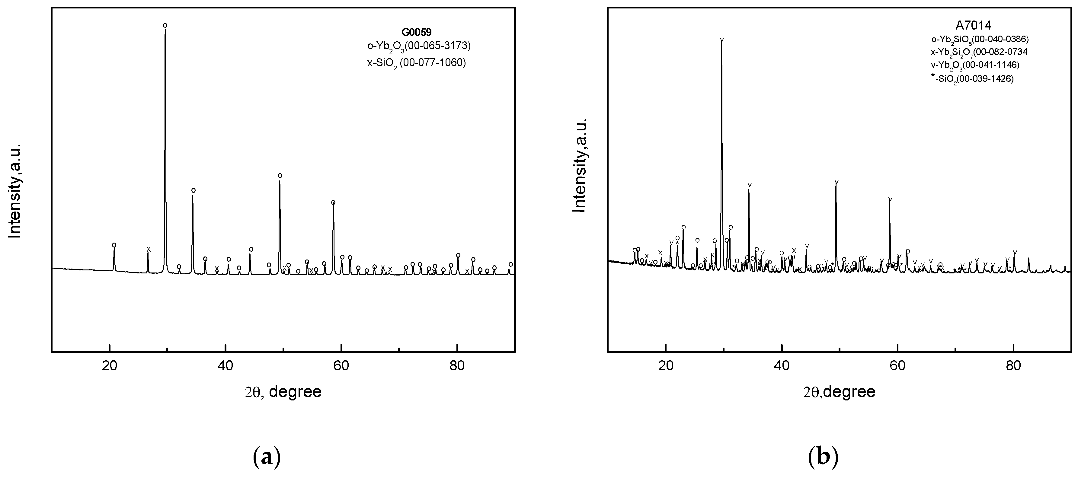
The XRD patterns of the raw oxide mixtures after sintering at a temperature of 1250 °C are in
Figure 1a, shows the presence of the initial oxides only. This can possibly be a result of using powders of rather large sizes, which was done so that the chemical reactions of the silicates’ syntheses did not go to completion. However, this fact may not be essential since the raw oxide charges were yet to be melted in the internal crystallization method (ICM) process. Increasing the temperature to 1650 °C (
Figure 1b) leads to the appearance of the silicate, but the initial oxides are still present.
The schematic of the internal crystallization method used for producing fibers is shown in
Figure 2. First, a molybdenum carcass was made by diffusion bonding of an assemblage of molybdenum foil and wires at such a regime that prevented the gaps between the neighboring wires from being filled with molybdenum of the foil. This led to the formation of the continuous channels with a cross-section shown in
Figure 2. Then, the raw oxide mixture was placed in a hopper settled at the top of the molybdenum carcass and melted in the furnace with the argon gas atmosphere. The melt infiltrated the oxide/molybdenum block, which was then pulled up to the cold zone of the furnace at the rates of 10, 50 and 250 mm/min to crystallize the fibers. The argon gas atmosphere was necessary to limit silica evaporation from the raw mixture of the oxides.
The size of the oxide/molybdenum block was ~5Χ15Χ65 mm3. Each block named as V1XYZ was divided into six specimens of the size 5Χ7Χ32 mm3 named V1XYZW. Here, XYZ are digits determining the number of a particular block: W = 1 to 6; numbers 1 to 3 denote the specimens from the top of the block. The specimens were tested in 3-point bending at room and high temperatures. The foil thickness, wire diameter and distance between the centers of neighboring wires were 0.04, 0.08 and 0.16 mm, respectively. This yielded a fiber volume fraction of 40.5%. However, the real geometry of the carcass after diffusion welding under some pressure can deviate from the ideal one, which leads to a decreased fiber volume fraction, so the average value for the specimens obtained was about 37%. This value follows from the ratio of a real thickness of a specimen to the ideal one; that is, the sum of foil thickness and wire diameters in the molybdenum carcass.
3. Microstructure of the Fibers
The microstructure of the composites was studied by using the Supra 50VP scanning electron microscope with INCA Energy+ energy-dispersive X-ray spectroscope. Images of the microstructure were obtained in secondary electrons at accelerating voltages of 5 to 20 kV. The crystal structure of the fibers was studied by the X-ray Xcaliber Gemini R diffractometer (graphite monochromator, MoKλ radiation, two-coordinates CCD imager).
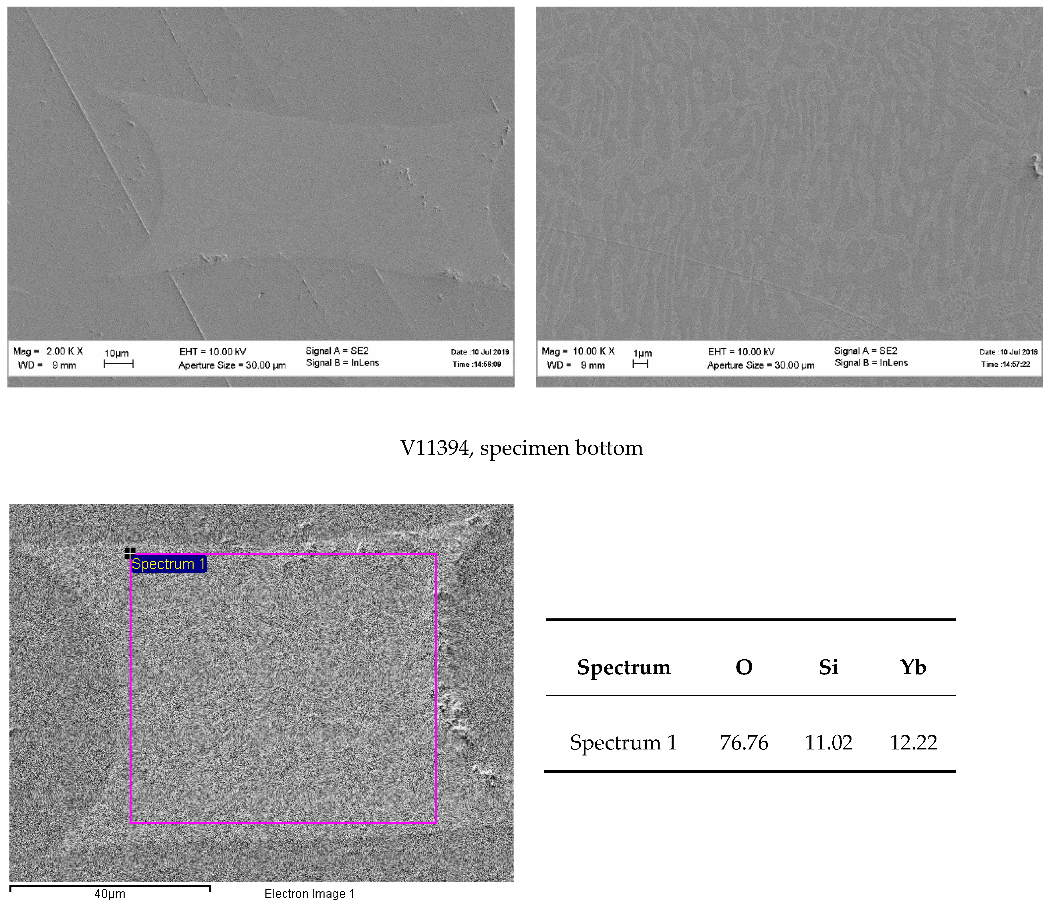
Consider first, the fibers were crystallized from the Yb
2O
3–SiO
2 mixture corresponding to Yb
2Si
2O
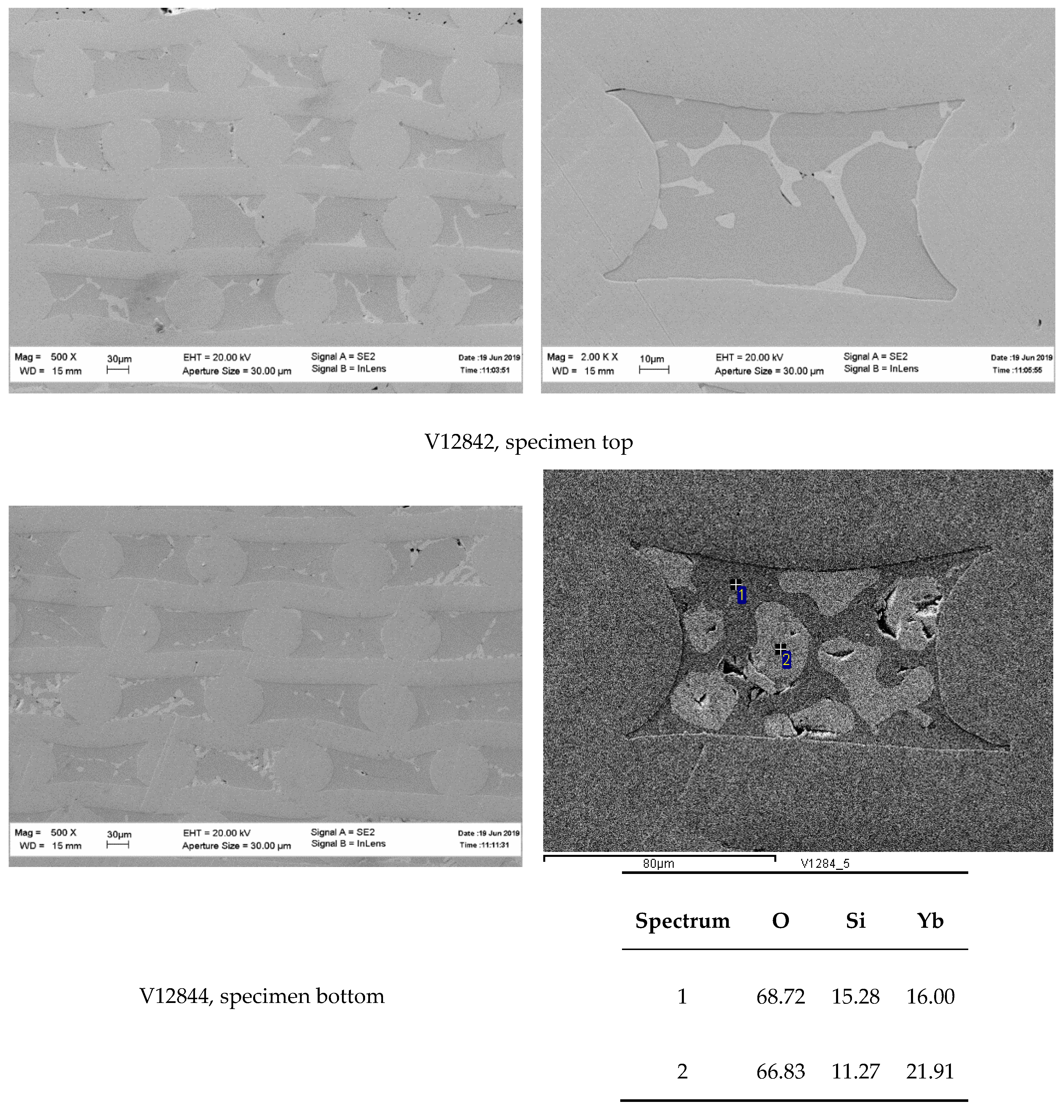
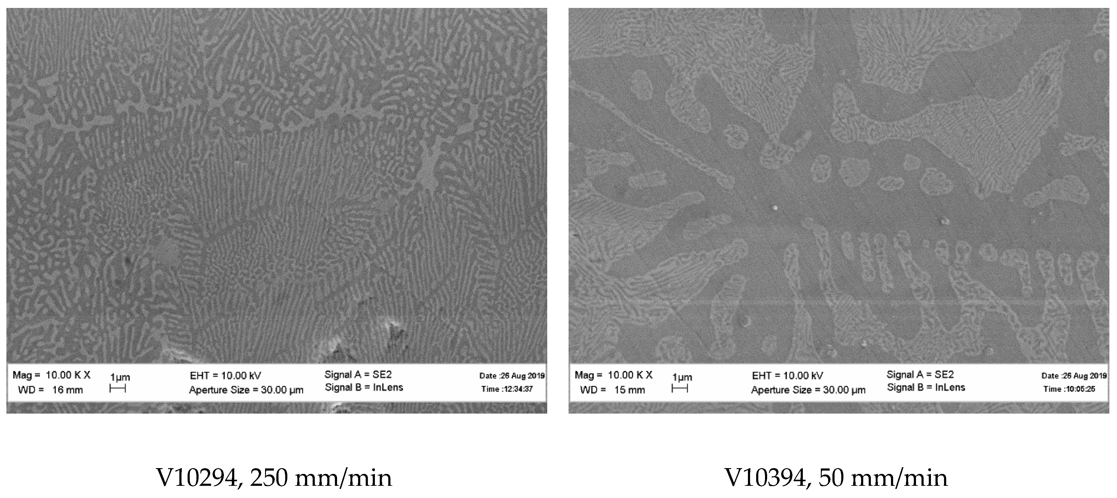
7. The microstructures of the fibers crystallized at the rates of 10 and 250 mm/min are presented in
Figure 3 and
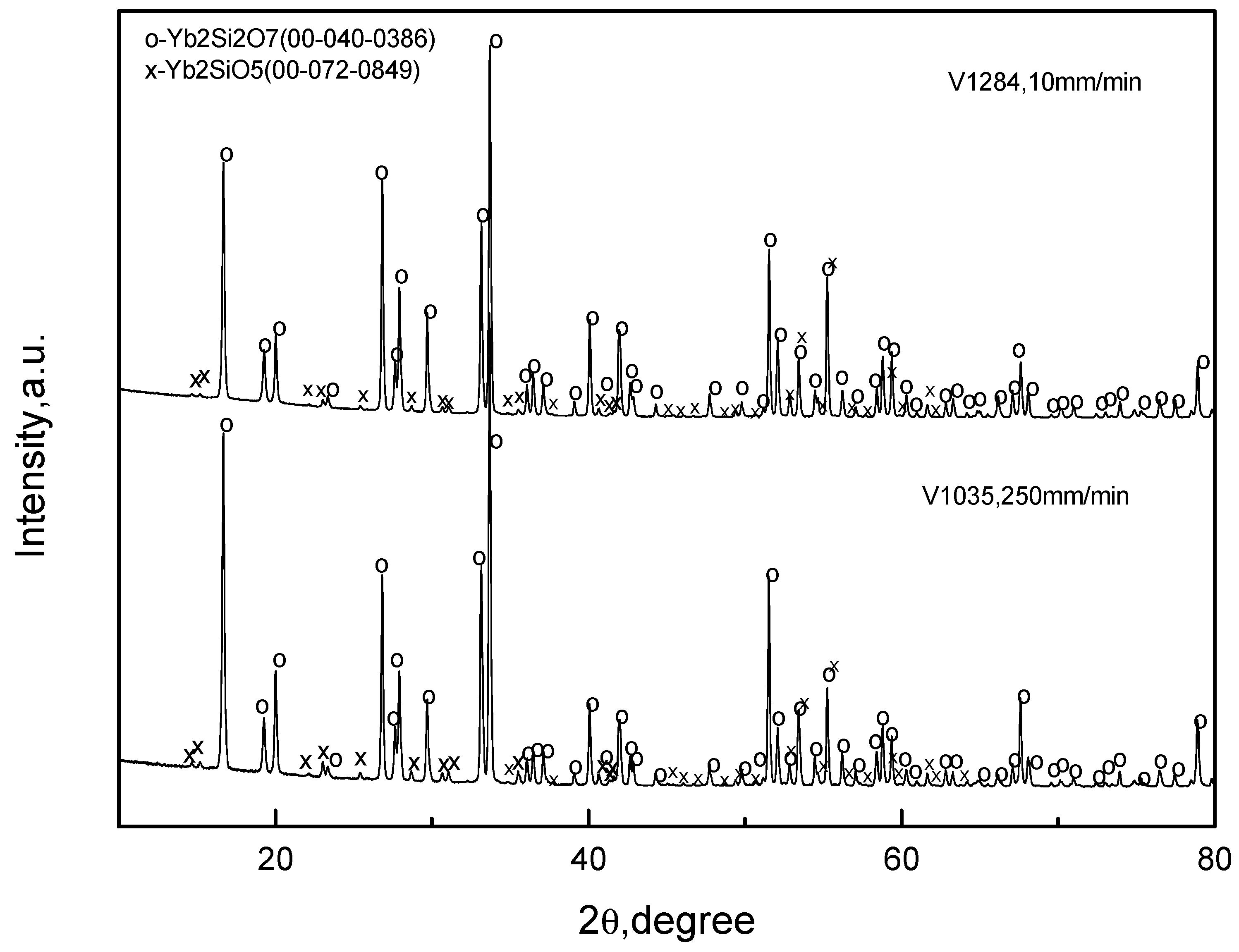
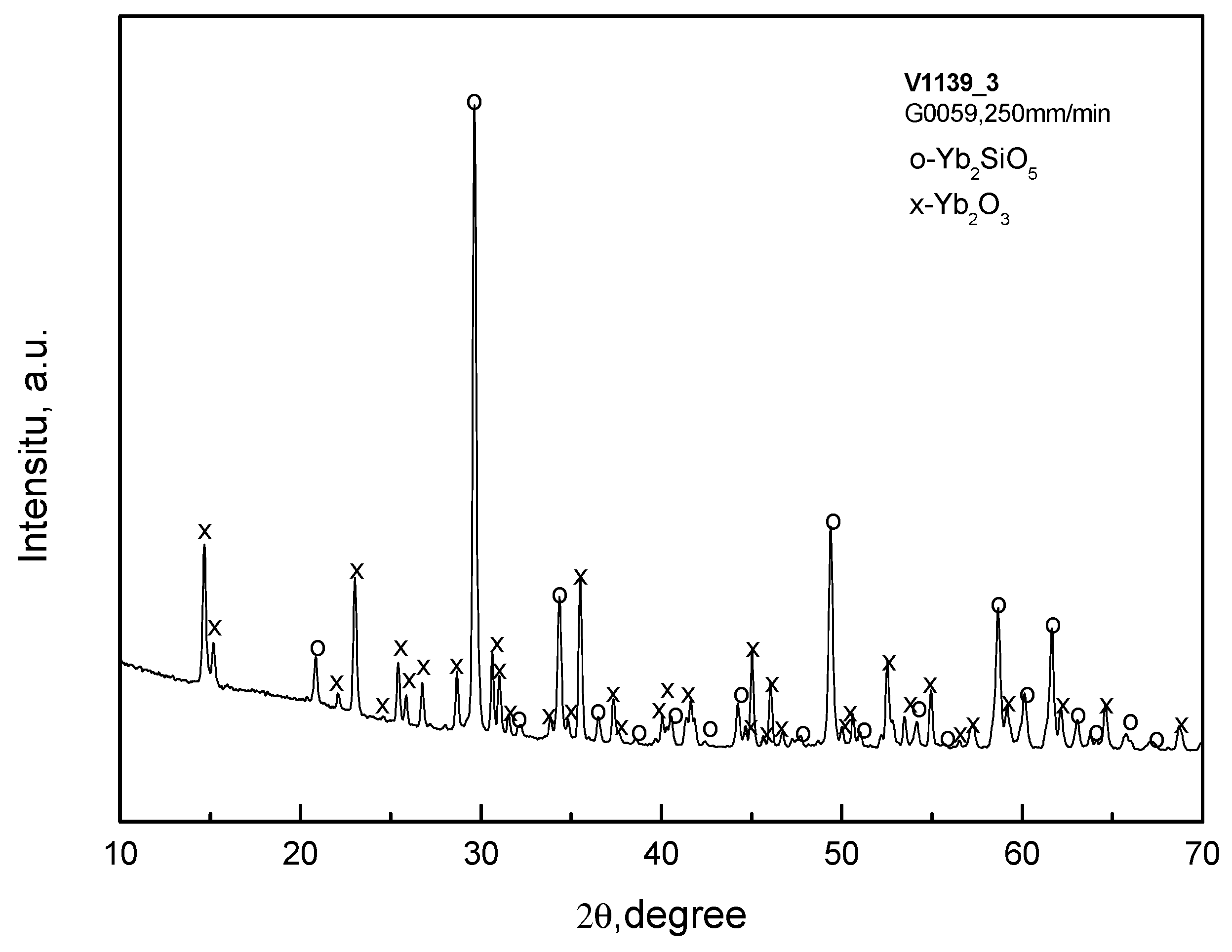
Figure 4, respectively. The crystallization started from the top of the oxide/molybdenum block and proceeded towards its bottom. Therefore, the microstructures of the fibers at the top and bottom of the specimens are shown. It can be seen that the fibers were non-homogeneous; they contained inclusions of monosilicate: the results of X-ray microanalysis presented in these figures revealed it as the “white” phase on the micrographs. The same result was obtained by the X-ray phase analysis presented in
Figure 5. There was no noticeable difference in the microstructure of the fibers obtained at the crystallization rates 10 and 250 mm/min. Qualitatively, the fibers from both the top and bottom of the specimens had similar microstructures.
The presence of the monosilicate in the fibers was most probably due to a partial evaporation of silica from the raw oxides’ melt. Hence, if an aim of the work was to obtain a homogeneous ytterbium disilicate fiber, then a correction of the mixture of raw oxides was needed.
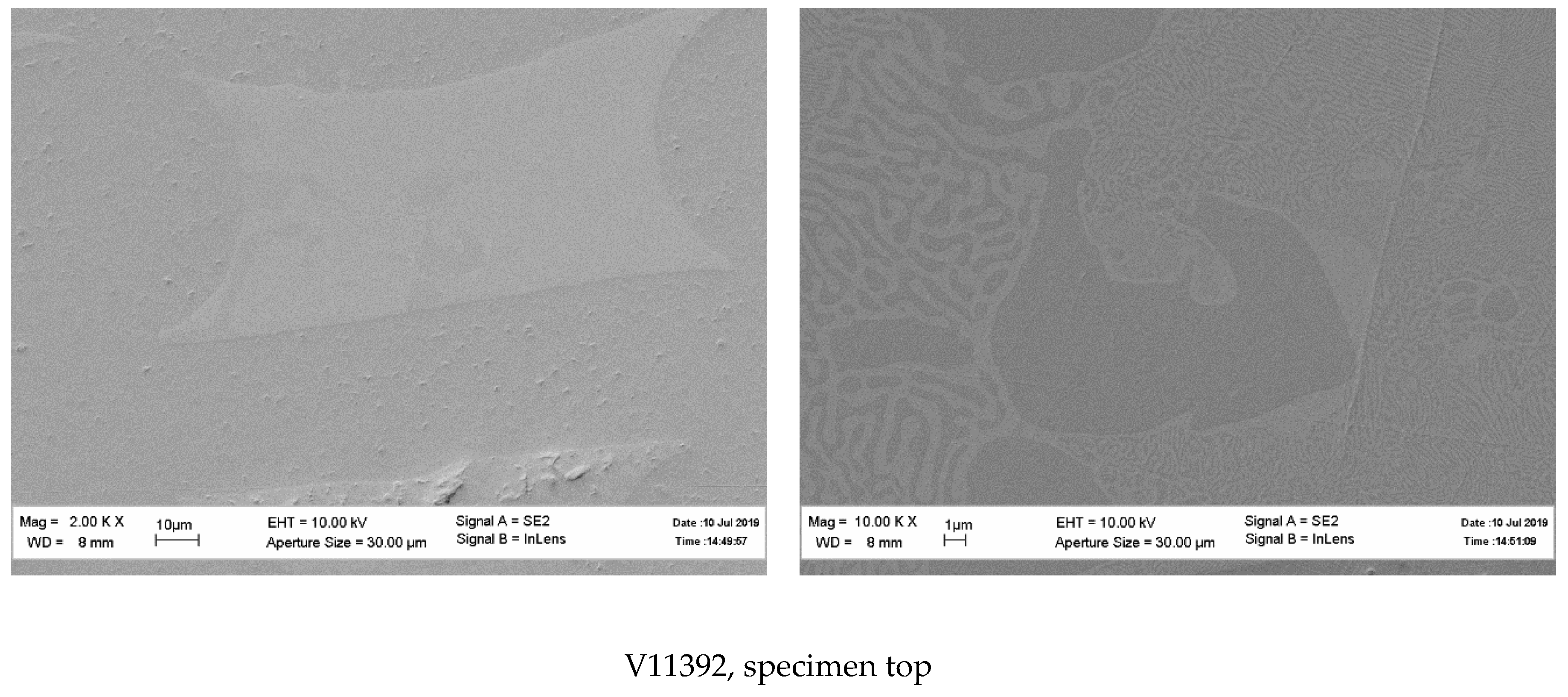
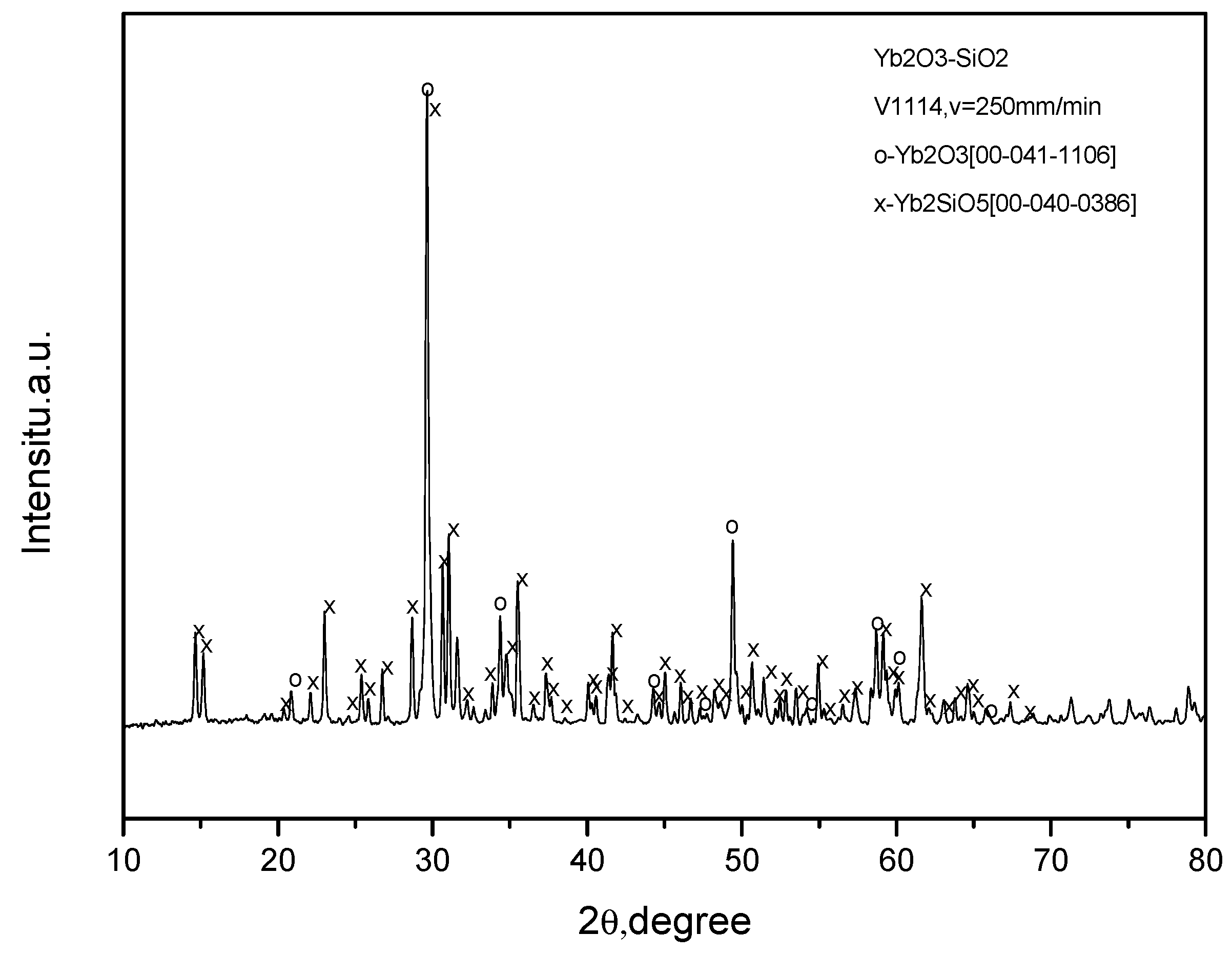
The microstructures of the fibers crystallized from the raw oxide mixtures corresponding to monosilicate are presented in
Figure 6. The X-ray diffraction pattern of a typical specimen of that type is given in
Figure 7. Again, the fiber microstructure was non-homogeneous. The fibers contained ytterbia as a component (
Figure 7), the ration Yb:Si > 1 (
Figure 6). Hence, a depletion of silica in the fiber was observed again.
The attempts to crystallize Y
2O
3–Y
2SiO
5 eutectic fibers also gave interesting results. X-ray analysis of the fibers crystallized from the raw oxide mixture G0046 revealed the presence of both Y
2O
3 cubic (la-3) and monoclinic Yb
2SiO
5 (l2/a(15)) phases (
Figure 8). At the same time, additional peaks d = 2.833 Å, d = 2.7553 Å and d = 1.776 Å can be seen, which do not correspond to any known phases. The SEM micrographs of the fibers presented in
Figure 9 show typical eutectic microstructures and ytterbia inclusions, which can also be a result of silica depletion in the melt.
In conclusion, note that the non-homogeneous microstructure of the fibers appears to be similar to the microstructures of Yb
2SiO
5 and Yb
2Si
2O
7 coatings fabricated by plasma spray deposition [
13]. After annealing, the Yb
2SiO
5 coating had Yb
2Si
2O
7 precipitates and vice versa.
4. Strength of the Fibers
As in [
5], the room temperature fiber strength was measured by testing oxide/molybdenum composite specimens in a three-point bending test using a universal testing machine with a computer recording the load/displacement curve. High temperature testing was done in vacuum. Only the load/time curves were recorded since the testing machine did not have an extensometer.
This procedure gave the effective strength of the fiber in the matrix [
5]. To calculate the fiber strength according to the rule of mixture, the values of the strength of the recrystallized molybdenum were assumed to be 450, 109, 85, 78 and 62 MPa at temperatures 20, 1000, 1200, 1300 and 1400 °C, respectively [
5]. The fiber volume fraction was taken as 0.37.
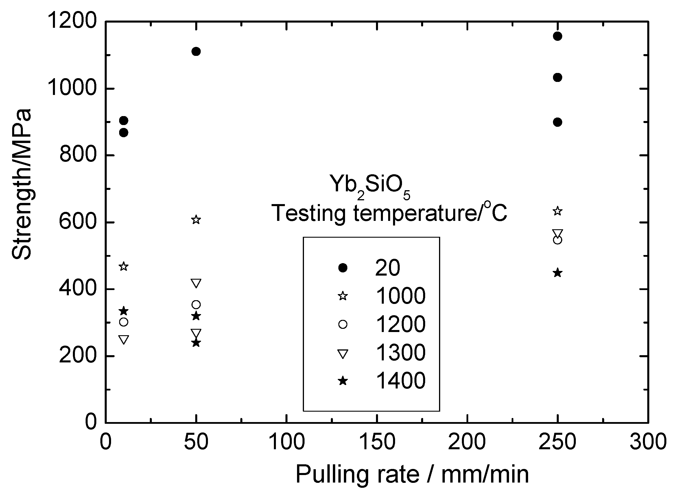
The dependence of monosilicate fibers strength on the crystallization rate is presented in
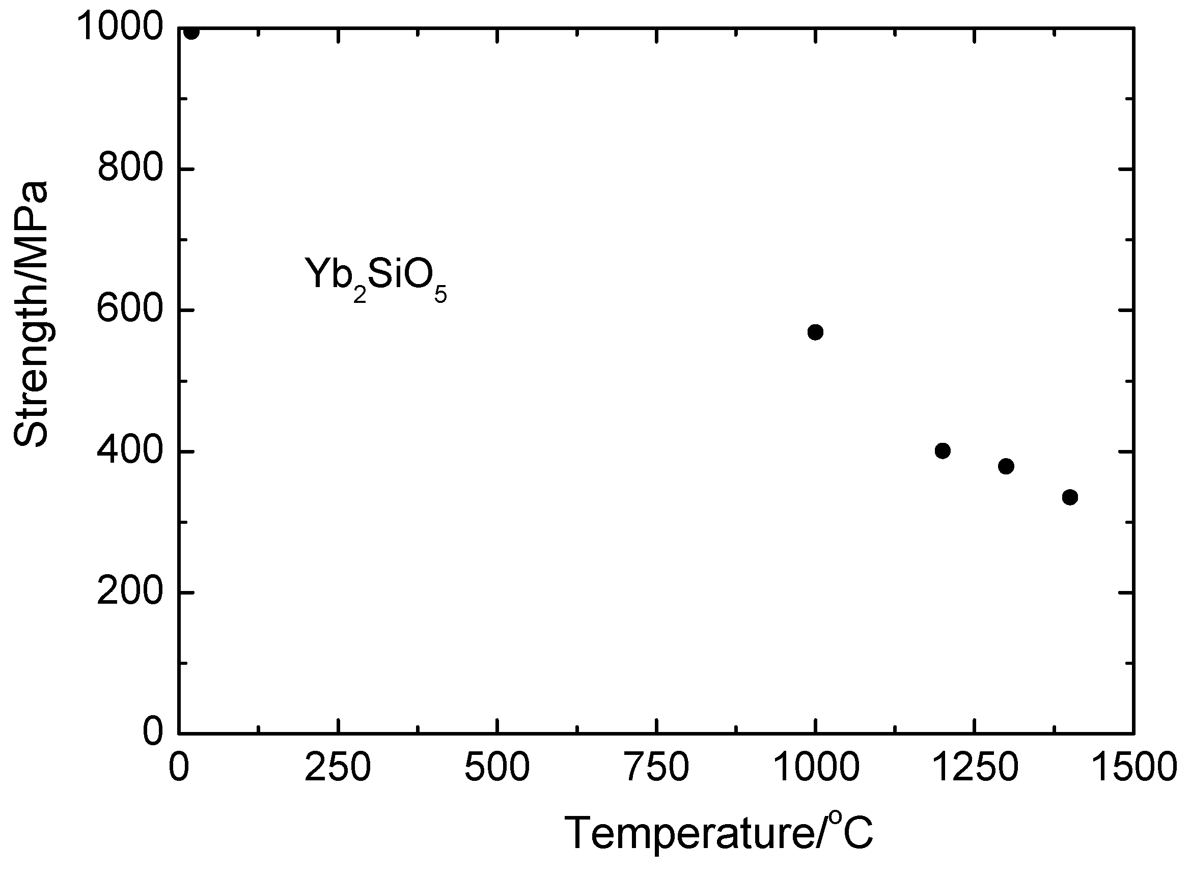
Figure 10. The fiber strength at room temperature did not seem to depend on the crystallization rate; however, at temperatures 1300 and 1400 °C, the experimental results indicated a weak dependence of those parameters: with the crystallization rate increasing, the fiber strength slightly increased. Neglecting the weakness’s crystallization rate dependence yields the dependence of the mean fiber strength on temperature—presented in
Figure 11.
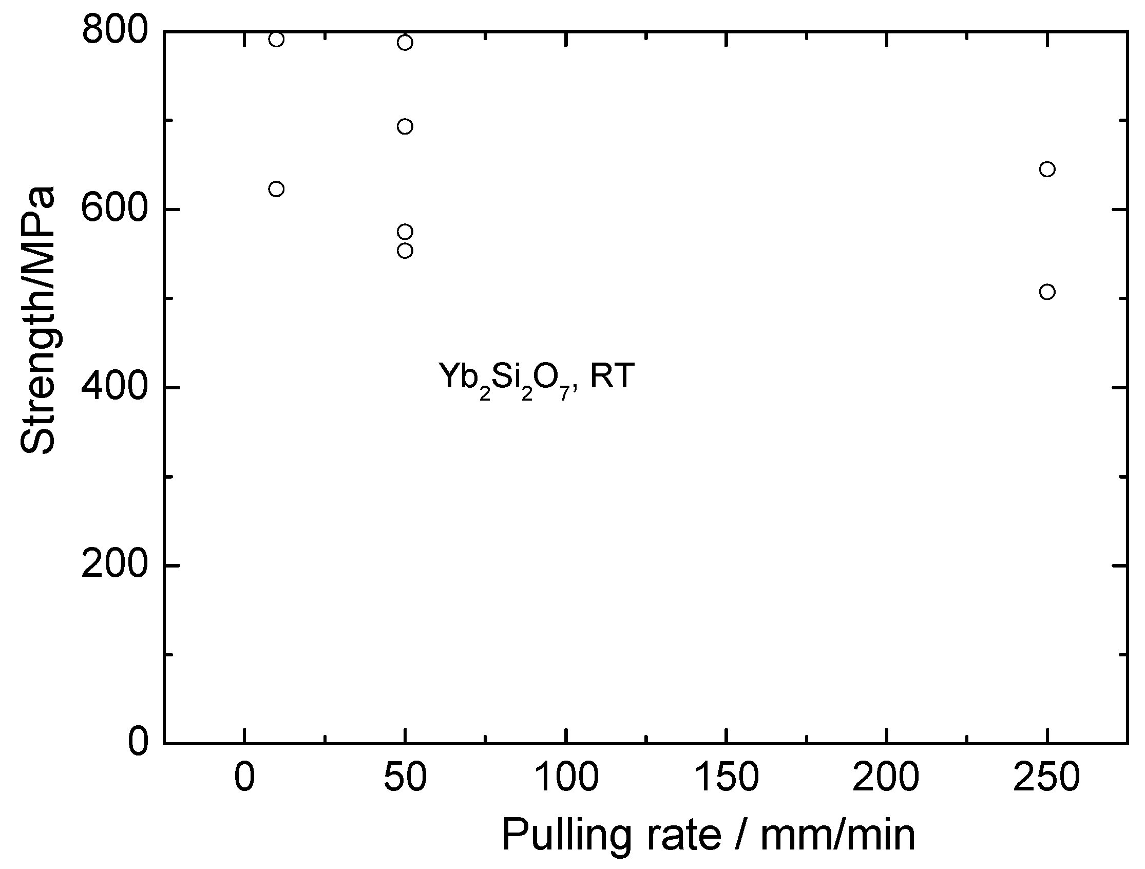
Room temperature strength of the fibers containing mainly ytterbium disilicate versus fiber crystallization rate is illustrated by
Figure 12. Comparing these data with those characteristic of the monosilicate fibers shows that disilicate fibers are essentially weaker than monosilicate-based fibers. Taking into account the presence of monosilicate in these fibers, the strength of pure ytterbium disilicate fibers can be expected to be even lower.
The room and high temperature strength of Yb
2O
3 –Yb
2SiO
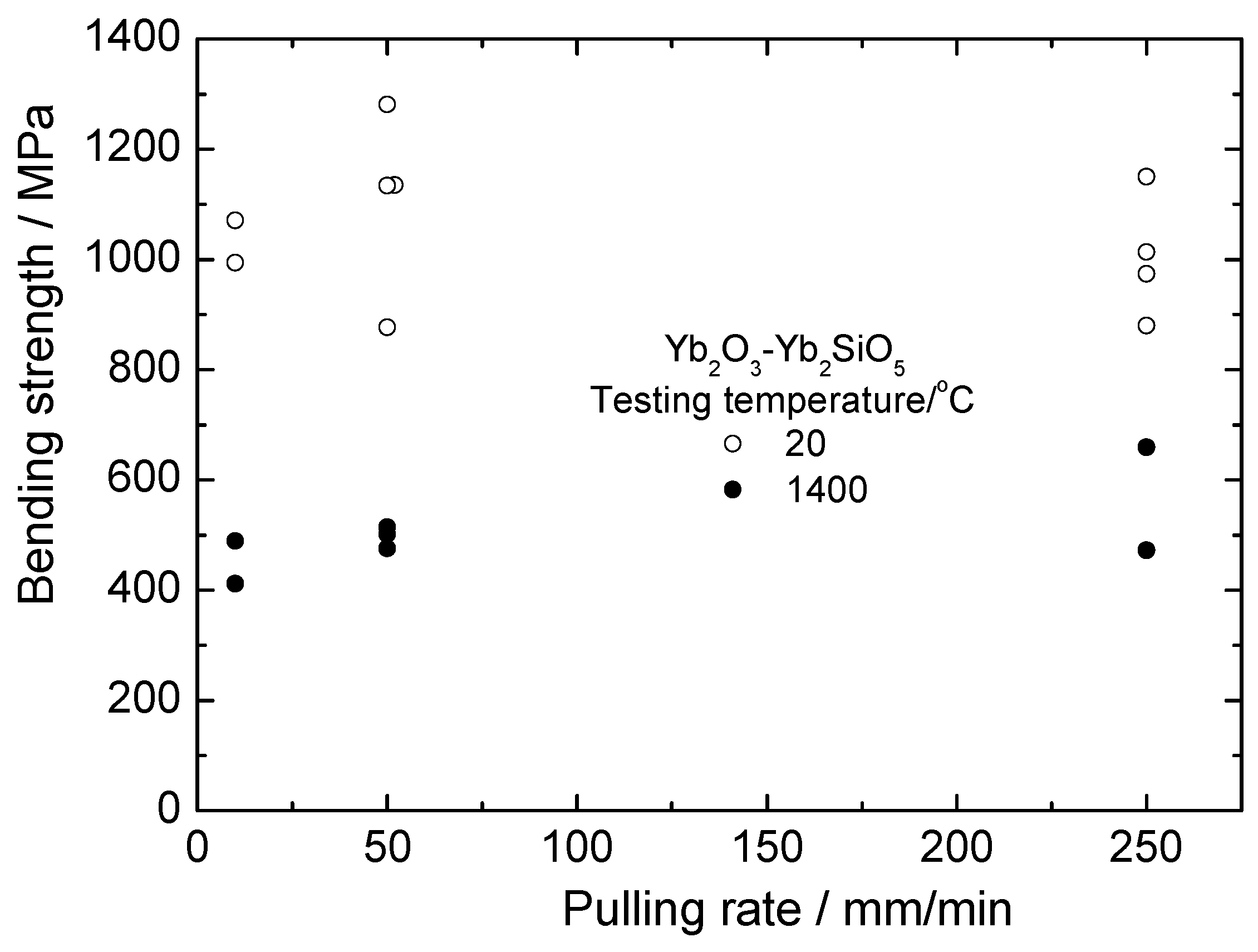
5 fibers is presented in
Figure 13. First, it can be seen that the strength of these fibers is noticeably higher than that of silicate fibers. Secondly, there is no essential dependence of the fiber strength on crystallization rate. This can be explained (i) by the absence of usual dependence of a characteristic size of the eutectic microstructure on crystallization rate and (ii) by the presence of large inclusions of ytterbia in the fibers, as can be seen in
Figure 9. Mechanical properties of yttrebia crystallized from the melt are unknown. The results obtained allow assuming the strength characteristics of such material to be sufficiently high.
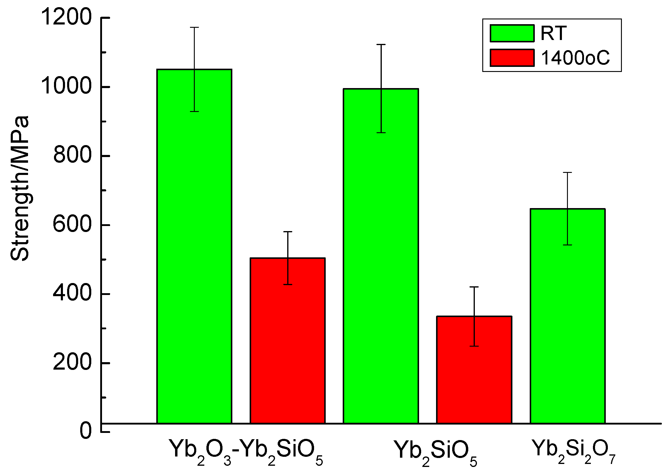
Calculations of statistical strength characteristics of the fibers obtained at all crystallization rates yield 1051 ± 128 and 504 ± 76 MPa for 20 and 1400 °C, respectively.
The comparison of strength characteristics of various fibers based on ytterbium silicates is presented in
Figure 14. Going along the horizontal axis of the Yb
2O
3–SiO
2 phase diagram from ytterbia toward silica, we observe the strength characteristics decreasing. An explanation of such a behavior of the materials crystallized from the melt should involve considering a number of factors, which are obviously beyond the scope the present work.
Finally, it should be noted that an optimal composition of the fibers under consideration depends on the usage of the fibers in a particular matrix. For example, varying the monosilicate to disilicate ratio can produce fibers with CTEs varying from 8 × 10⁻⁶ K−1 to 4 × 10⁻⁶ K−1. Potential molybdenum matrices have CTE around 6 × 10⁻⁶ K−1; for oxide matrices, this value is around 8 × 10⁻⁶ K−1. The inclusion of ytterbia into consideration expands possibilities of the fiber microstructure optimization.
5. Conclusions
The internal crystallization method allowed, for the first time, obtaining ytterbium silicate fibers.
All fibers have a composite microstructure; namely, Yb2SiO5–Yb2Si2O7 and Yb2O3 –Yb2SiO5.
Strength characteristics of the fibers increase inversely to ytterbia disilicate content. The mean strength, at the temperature 1400 °C, of the fibers composed of the Yb2O3 –Yb2SiO5 eutectic microstructure with ytterbia inclusions, reaches ~500 MPa.
A variety of mechanical, physical and chemical properties of the silicates will allow optimizing the fibers’ compositions to make them suitable for usage in a number of potential matrices.
Author Contributions
Conceptualization, S.M. and A.K.; investigation, A.K., S.G., O.S. and M.N.; writing—review and editing, S.M.; project administration and funding acquisition, S.M.
Funding
This research was funded by Russian Science Federation, grant number 16-19-10624-P.
Acknowledgments
The authors thanks V.M. Prokopenko, N.I. Novokhatskaya and N.A. Prokopenko for their help in the experimental work and A.A. Serebryakova for improving the English.
Conflicts of Interest
The authors declare no conflict of interest. The funders had no role in the design of the study; in the collection, analyses, or interpretation of data; in the writing of the manuscript, or in the decision to publish the results.
References
- Brenner, S.S. Mechanical behavior of sapphire whiskers at elevated temperatures. J. Appl. Phys. 1962, 33, 33–39. [Google Scholar] [CrossRef]
- La Belle, H.E., Jr.; Mlavsky, A.I. Growth of sapphire filaments from the melt. Nature 1967, 216, 574–575. [Google Scholar] [CrossRef]
- Yoshikawa, A.; Epelbaum, B.M.; Hasegawa, K.; Durbin, S.D.; Fukuda, T. Microstructures in oxide eutectic fibers grown by a modified micro-pulling-down method. J. Cryst. Growth 1999, 205, 305–316. [Google Scholar] [CrossRef]
- Calow, C.A.; Moore, A. No hope for ceramic whiskers or fibers as reinforcement of metal matrix at high temperatures. J. Mater. Sci. 1972, 7, 543–558. [Google Scholar] [CrossRef]
- Mileiko, S. Metal and Ceramic Based Composites; Elsevier: Amsterdam, The Netherlands, 1997. [Google Scholar]
- Mileiko, S.T.; Kazmin, V.I. Crystallization of fibers inside a matrix: A new way of fabrication of composites. J. Mater. Sci. 1992, 27, 2165–2172. [Google Scholar] [CrossRef]
- Mileiko, S.T.; Kazmin, V.I. Structure and mechanical properties of oxide fiber reinforced metal matrix composites produced by the internal crystallization method. Compos. Sci. Technol. 1992, 45, 209–220. [Google Scholar] [CrossRef]
- Bakan, E.; Sohn, Y.J.; Kunz, W.; Klemm, H.; Vaßen, R. Effect of processing on high-velocity water vapor recession behavior of Yb silicate environmental barrier coatings. J. Eur. Ceram. Soc. 2019, 39, 1507–1513. [Google Scholar] [CrossRef]
- Rohbeck, N.; Morrell, P.; Xiao, P. Degradation of ytterbium disilicate environmental barrier coatings in high temperature steam atmosphere. J. Eur. Ceram. Soc. 2019, 39, 3153–3163. [Google Scholar] [CrossRef]
- Nasiri, N.A.; Patra, N.; Jayaseelan, D.D.; Lee, W.E. Water vapour corrosion of rare earth monosilicates for environmental barrier coating application. Ceram. Int. 2017, 43, 7393–7400. [Google Scholar] [CrossRef]
- Tian, Z.; Zheng, L.J.; Wang, P.; Wan, J.; Li, J.; Wang, J. Theoretical and experimental determination of the major thermo-mechanical properties of RE2SiO5(RE = Tb, Dy, Ho, Er, Tm, Yb, Lu, and Y) for environmental and thermal barrier coating applications. J. Eur. Ceram. Soc. 2016, 36, 189–202. [Google Scholar] [CrossRef]
- Fernandez-Carrion, A.J.; Allix, M.; Becerro, A.I. Thermal Expansion of Rare-Earth Pyrosilicates. J. Am. Ceram. Soc. 2013, 96, 2298–2305. [Google Scholar] [CrossRef]
- Richards, B.T.; Zhao, H.; Wadley, H.N.G. Structure, composition, and defect control during plasma spray deposition of ytterbium silicate coatings. J. Mater. Sci. 2015, 50, 7939–7957. [Google Scholar] [CrossRef]
© 2019 by the authors. Licensee MDPI, Basel, Switzerland. This article is an open access article distributed under the terms and conditions of the Creative Commons Attribution (CC BY) license (http://creativecommons.org/licenses/by/4.0/).
