Article

Development of Electrophoretic Deposition Prototype for Continuous Production of Carbon Nanotube-Modified Carbon Fiber Fabrics Used in High-Performance Multifunctional Composites

1
Swerea SICOMP AB, P.O. Box 271, SE 941 26 Piteå, Sweden
2
Department of Engineering Sciences and Mathematics, Luleå University of Technology, SE 971 87 Luleå, Sweden
*
Author to whom correspondence should be addressed.
Fibers 2018, 6(4), 71; https://doi.org/10.3390/fib6040071
Submission received: 3 September 2018 / Revised: 18 September 2018 / Accepted: 27 September 2018 / Published: 28 September 2018

Abstract

:
An electrophoretic deposition (EPD) prototype was developed aiming at the continuous production of carbon nanotube (CNT) deposited carbon fiber fabric. Such multi-scale reinforcement was used to manufacture carbon fiber-reinforced polymer (CFRP) composites. The overall objective was to improve the mechanical performance and functionalities of CFRP composites. In the current study, the design concept and practical limit of the continuous EPD prototype, as well as the flexural strength and interlaminar shear strength, were the focus. Initial mechanical tests showed that the flexural stiffness and strength of composites with the developed reinforcement were significantly reduced with respect to the composites with pristine reinforcement. However, optical microscopy study revealed that geometrical imperfections, such as waviness and misalignment, had been introduced into the reinforcement fibers and/or bundles when being pulled through the EPD bath, collected on a roll, and dried. These defects are likely to partly or completely shadow any enhancement of the mechanical properties due to the CNT deposit. In order to eliminate the effect of the discovered defects, the pristine reinforcement was subjected to the same EPD treatment, but without the addition of CNT in the EPD bath. When compared with such water-treated reinforcement, the CNT-deposited reinforcement clearly showed a positive effect on the flexural properties and interlaminar shear strength of the composites. It was also discovered that CNTs agglomerate with time under the electric field due to the change of ionic density, which is possibly due to the electrolysis of water (for carboxylated CNT aqueous suspension without surfactant) or the deposition of ionic surfactant along with CNT deposition (for non-functionalized CNT aqueous suspension with surfactant). Currently, this sets time limits for the continuous deposition.

1. Introduction

The use of fiber-reinforced polymer (FRP) composites has expanded substantially for various applications in a wide range of industries, such as aerospace and aeronautics, automotive, sport, construction, and marine. Extensive research and development has led to remarkable improvements in the performance of the FRP composites. In spite of excellent in-plane properties, FRP composites typically show poor out-of-plane performance which is dominated by the polymer matrix. The presence of matrix-rich regions formed in the gaps between the interlaced fiber bundles is another critical drawback. These regions, where cracks easily initiate and propagate, are difficult to reinforce with traditional microscale fibers. Various nanoscale materials have been explored for the selective reinforcement of matrix-rich regions, among which the carbon nanotube (CNT) has been suggested as an ideal candidate because of its outstanding mechanical, electrical and thermal properties [1,2]. The growth of CNTs on the surface of fibers changes the characteristics of the fiber surface and the fiber/matrix interface. With CNTs to bridge the interface, the interfacial strength of the fiber is improved. Furthermore, CNTs bridge the gap between delaminated layers therefore increases the toughness of the composite [3,4,5]. Compared to other methods, such as soaking, dip, and spray-coating for doping nanoparticles onto substrates, chemical vapor deposition (CVD) is reportedly able to grow well-aligned CNTs perpendicularly on fiber and fabric surfaces [3,4,5,6], leading to an enhanced fiber/polymer interfacial load transfer. In spite of the efficiency for the growth of CNTs on a variety of surfaces, the use of high temperatures and pre-deposited catalysts together with the difficulties in processing large panels imposes serious limitations on practical applications of the CVD technique in scaled-up production. Furthermore, high-temperature processing removes any sizing that is conventionally applied to fibers during the manufacturing of fibers, and the CVD reaction may also degrade the fiber strength [7].
One promising technique that is being developed for attaching CNTs on the surface of fiber reinforcement is electrophoretic deposition (EPD). EPD is essentially a two-step process. In the first step, particles suspended in a liquid are forced to move toward an electrode by applying an electric field (electrophoresis); in the second step, the particles collect at the electrode and form a coherent deposit [8]. In contrast to many colloidal processes, suspensions with relatively low solids loading are preferred; the low viscosity of suspensions that are usually water based provides processing and handling advantages in the EPD process. Research on using the EPD technique to deposit carbon nanomaterials on fiber reinforcement (mainly carbon fibers) for polymeric composites seems to boost up from 2006, as viewed from the published scientific articles, including some highly cited ones [7,8,9]. The improvement of interfacial properties and the electrical conductivity of composites have been reported. As stated additionally in these publications, EPD offers the advantages of low cost, process simplicity, uniformity of deposits, control of deposit thickness, and microstructural homogeneity; hence, it is considered a cost-effective method that is amenable to scaling up to large dimensions.
However, in most publications, in order for fiber reinforcement to be deposited, it needs to be cut and mounted on a metal frame, acting as one electrode. The mounted reinforcement and one or two metal plates acting as the counter electrode(s) are then vertically inserted into an EPD bath for deposition. The metal frame will be taken out from the bath after each run of deposition, followed by dismounting and collecting the deposited reinforcement. Regardless of the deposition time in each run, such a process is certainly not a continuous operation. This also implies that the discoveries in the discontinuous deposition processes cannot be fully utilized in a continuous process. Among the publications related to nanoparticles coating via EPD, only a few provide the information of continuous deposition. Santhanagopalan et al. reported the continuous deposition of CNTs on long strips of metal foil; a pump with a flow rate of eight mL/min was used to replenish the CNT dispersion [10]. Three research groups, led by Jiang [11,12], Li [13], and Huang [14], respectively, reported the coating of graphene oxide on carbon fibers and fiber tows continuously via EPD. The discontinuous EPD process is also very likely to increase the CNT discards, which will increase the production cost of CNT-deposited fiber reinforcement using this technique due to the high cost of CNT materials. Furthermore, it will impose a serious negative impact on the environment, since there has not yet been any efficient way to recycle CNTs.
The current study reports the production of CNT-deposited carbon fiber fabrics via continuous EPD using a newly developed prototype. The influence of deposition conditions and the deposit yield on the flexural properties and interlaminar shear strength of composites is the focus of this paper. The geometrical defects in the fiber reinforcement due to the wetting and drying processes along with the EPD treatment are analyzed by optical microscopy. The essence of CNT aqueous suspension that limits the continuous deposition to be further scaled up is analyzed, and feasible solutions are suggested.

2. Experimental

2.1. Materials and Processing

Two commercial multi-walled carbon nanotubes (MWCNTs) aqueous suspensions were tested in the continuous EPD process prototype. AquacylTM AQ0302 purchased from Nanocyl, Belgium, is a deionized water dispersion of 3 wt% of NC7000TM (an industrial MWCNTs product without any chemical functionalization produced via the catalytic chemical vapor deposition process) containing an anionic surfactant that is not volatile, which facilitates the dispersion and imparts a negative charge to the CNTs. Hereby, the NC7000 can move toward and deposit on the anode. The NC7000 has an average diameter of 9.5 nm, an average length of 1.5 µm, a surface area of 250–300 m2/g, a volume resistivity of 10−4 Ω.cm, and a carbon purity of 90%. A two gram/liter suspension of carboxylated MWCNTs (PD15L5-20-COOH) in deionized water free of surfactant was purchased from Nanolab, Milpitas, CA, USA. The PD15L5-20-COOH has an average diameter of 15 ± 5 nm, an average length of 5–20 microns, a surface area of 200–400 m2/g, and a carbon purity higher than 95%. The carboxyl group, –COOH, is grafted on the surface of CNTs via covalent bonding, and will dissociate to COO– in water to hold the CNTs apart, preventing agglomeration via the repulsive forces. Hereby, the PD15L5-20-COOH is negatively charged, and hence can move toward and deposit on the anode. Both commercial CNT aqueous suspensions as received were diluted to the defined concentrations −0.5 wt%, 0.3 wt%, 0.1 wt%, 0.025 wt% and 0.005 wt%, respectively—with demineralized water, and dispersed well prior to the EPD process.
A unidirectional weave composed of Tenax HTS45 E23 12K for warp and hot melt 70 Tex verre polyamide for weft, which has a surface weight of 205 g/m2, was purchased from Porcher composites and used as the reinforcement for the composites.
An epoxy system, Araldite® LY 556/Aradur® 917/accelerator DY 070 (Huntsman) with a mixing ratio of 100/90/0.5 (parts by weight), was used as the matrix for the composites.
The mechanism underpinning the continuous EPD is that against the fixed counter electrode the fiber reinforcement acts as a movable electrode that is pulled through EPD bath at a certain speed so that every spot on the reinforcement will be deposited for a defined time. Due to a related patenting process, the sketch of the continuous EPD prototype cannot be shown in the current paper. In this prototype, the distance between the anode (carbon fiber (CF) fabric) and cathode (two aluminum plates positioned opposite to both surfaces of the fabric) is fixed as 10 mm so as to generate an electric field with the strength of 10 V/cm at a direct current (DC) power supply of 10 V. The strength of the electric field was decided by several factors: (1) the resistance of the deposit is almost independent of the electric field from 10 V/cm and above, especially for the suspension with a concentration lower than 0.05 wt% [13]; lower electric fields lead to higher resistance and a lower deposit yield, (2) higher power leads to increasing energy consumption and promotes the electrolysis of water theoretically occurring at a potential of 1.23 V, which will generate bubbles that behave as insulation between CFs and CNT suspension, resulting in vacancies on the fabric without CNT deposit. In order to reduce the impact of water electrolysis and improve the dispersion of CNTs as well as postpone the aggregation of CNTs (the phenomena and reasons are described in the following sections), ultrasonication together with a circulation system was applied during the entire EPD process. The fabric was pulled through the EPD bath at a speed of 50 mm/min, leading to a deposition time of three minutes for every spot on the fabric.
Composite laminates using pristine CF fabrics, demineralized water-treated CF fabrics using the same deposition procedure in the EPD prototype but without CNTs, and CNT-deposited CF fabrics via continuous EPD, respectively, were manufactured using the resin transfer molding (RTM) technique. Fabrics were sealed in a steel mold that was warmed to 40 °C and then infused with the resin, which was also heated to 40 °C, at a pressure of three bar. The warming of the mold and resin is to facilitate the resin flow and infusion. After completion of the infusion, the laminates were cured at 80 °C under a pressure of three bar for 16 hours, followed by post-curing free standing in an oven at 140 °C for four hours.

2.2. Characterization

The deposition of CNTs on the CF fabric was characterized by an extreme high resolution scanning electron microscope (XHR-SEM, Magellan 400, FEI).
The pH value of the CNT suspension during the continuous EPD process was monitored by a pH meter (Five Easy F20, Mettler Toledo).
The morphology of untreated and treated fabrics was studied by an optical microscope (SMZ1270, Nikon). The morphology of specimens after mechanical testing was characterized by an optical microscope (MA200, Nikon).
Three-point bending test was performed according to ASTM D7264 standard [15] on an Instron 4411 universal testing machine equipped with a 5-kN load cell and standard Instron bending set-up. The span length was set to 124.8 mm, and crosshead motion was set to 1 mm/min. Stress at the outer surface in the load span region was calculated according to Equation (1):
σ = 3 P L 2 b h 2
where P is the applied force, L is the span length, b is the sample width, and h is the sample thickness. Strain at the outer surface in the load span region was calculated according to Equation (2):
ε = 6 h δ L 2
where δ is the mid-span deflection. The flexural elastic modulus was calculated in the strain region 0.05–0.20% (linear fit of stress–strain curves). Maximum flexural stress σB and strain at maximum flexural stress εB were also obtained.
Short beam strength test was performed according to ASTM D2344 standard [16] on an Instron 4411 universal testing machine equipped with a 5-kN load cell and a three-point bending short-beam test set-up. The span length was set to 15.2 mm, and crosshead motion was set to 1 mm/min. Interlaminar shear strength (ILSS) was calculated according to Equation (3):
F s b s = 0.75 · P m b h
where Pm is the maximum load observed during the test.

3. Results and Discussions

3.1. Dependence of Depostion Status and Deposit Yield on Concentration of CNT Suspension

Figure 1 exemplifies the SEM images randomly taken from the fabrics treated via the continuous EPD process. These show the deposition status of CNTs (Nanocyl product) on the CF fabric depending on the concentrations of CNTs in the EPD bath. It is noted that it took 1 h to coat one full roll with a length of three meters while every spot on the fabric was submerged in the EPD bath for three minutes, since the fabric was pulled through the EPD bath at a speed of 50 mm/min.
It is clearly shown from the SEM images that at a CNT concentration of 0.1 wt% and above, very dense CNT deposits are formed, particularly on the surface of the fabric, where heavily entangled CNTs are found. Such a thick deposit layer on the surface indeed prevents CNTs from being deposited on CFs beneath the surface, leading to insufficient CNTs that will reinforce the matrix-rich regions in the gaps between the interlaced fiber bundles. More diluted suspension leads to the more homogeneous deposition of CNTs across the fabric. Therefore, only suspension with a concentration of 0.1 wt%, 0.025 wt%, and 0.005 wt%, respectively, was used for producing CNT-deposited fabrics for composites processing and property evaluation in the following work. However, it is noted that even with the much-diluted suspension, 0.025 wt%, agglomerated CNTs were formed in the deposits (Figure 1(d2)).
The deposit yield on the fabric was 4.94 mg and 1.41 mg, corresponding to the use of CNT suspension with a concentration of 0.025 wt% and 0.005 wt%, respectively. This indicates that the dependence of deposit yield on the concentration of CNT suspension at a given electric field and deposition time does not follow a linear relationship. Such a small amount of CNT deposit, however, can lead to a pronounced property enhancement of composites (as shown in the following sections), which indicates that the CNT-deposited fiber reinforcement via the developed continuous EPD process has great potential to be used for the development of high-performance and multifunctional composites.

3.2. Aggregation of CNTs with Time during Continuous EPD Process

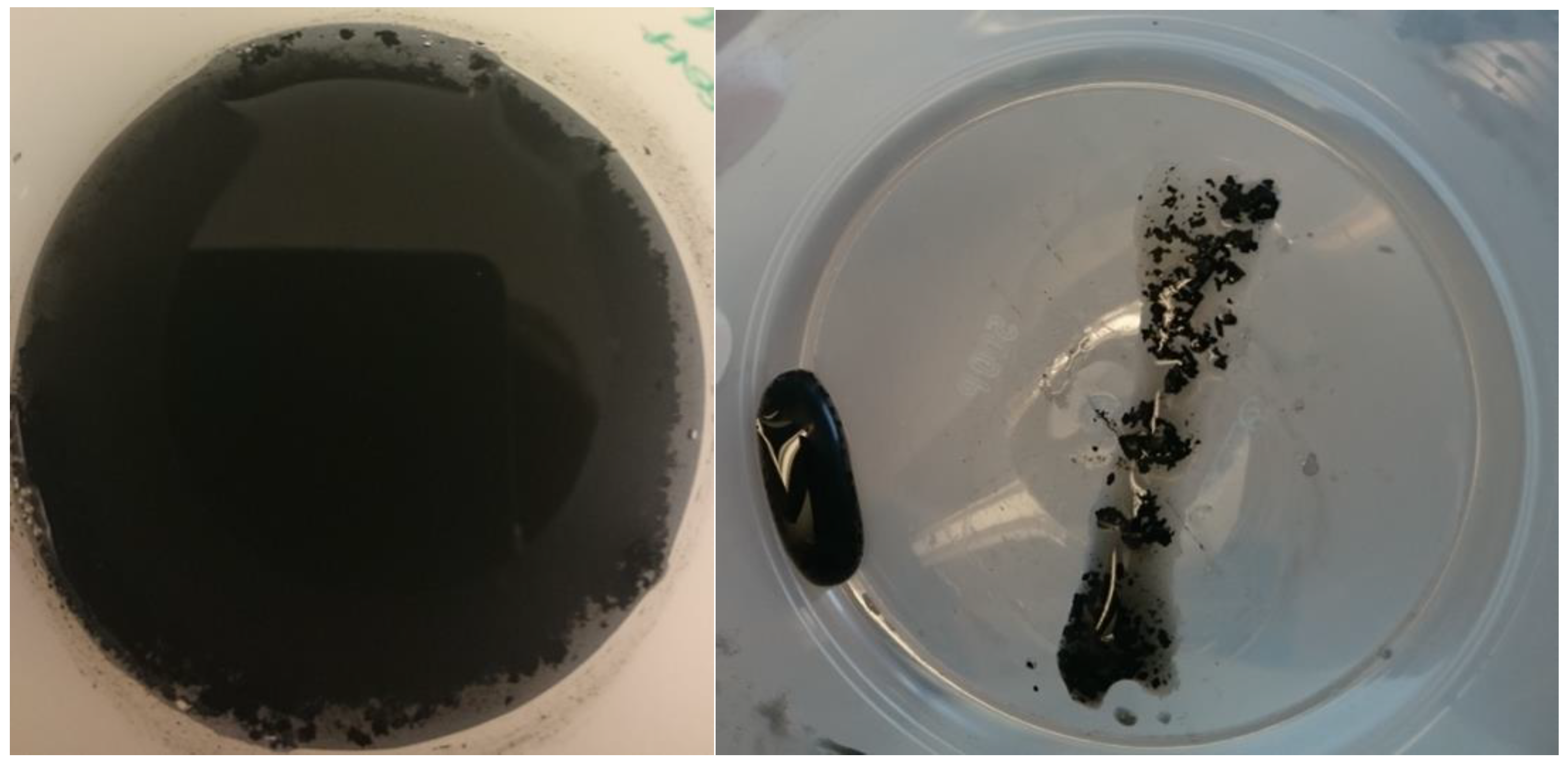
Prior to the continuous EPD process, the diluted suspensions of both CNT aqueous products were freshly prepared and exhibited good dispersion. Still, CNT agglomerates started to occur in the EPD bath, and after three hours of deposition, a large number of visible chunks were found, as shown in Figure 2. This implies that even with replenished CNT suspension, the deposition quality will deteriorate, and deposit yield will be reduced with time when the continuous EPD process proceeds, since the CNT aggregates become too large and numerous to be moved toward the fabric; hence, no coherent deposit will be formed eventually.
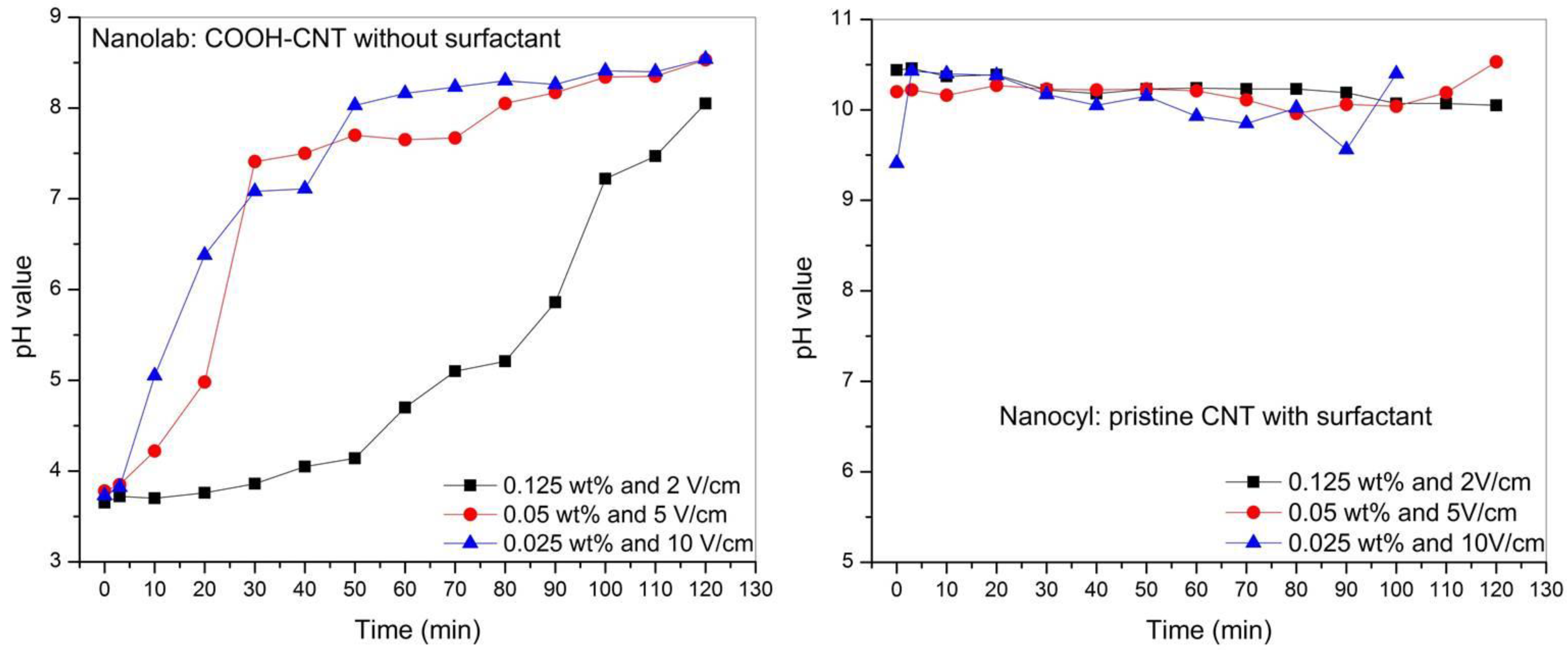
The pH value of the CNT suspensions with different concentrations prepared by diluting the two commercial CNT water products was monitored in a two-hour continuous deposition process. Figure 3 illustrates the evolution of pH values with time for CNT suspensions with different concentrations and at different electric fields. However, the product of the concentration of CNT suspension and the strength of electric field is constant, with an absolute value of 0.25. It is found that the pH value of the Nanolab suspensions keeps increasing with time, and by the end of two hours, the suspension has become alkaline from originally acidic suspensions. In addition, the pH value of more diluted suspension seems to increase faster than the more concentrated suspension in the first hour; afterwards, the pH value of the more concentrated suspension increases faster. On the other hand, the change of pH value within two hours was almost negligible in Nanocyl suspensions. Thus, it is speculated that the agglomeration of carboxylated CNTs (Nanolab) is caused by the change of the ions’ density because of electrolysis of water; while the agglomeration of non-functionalized CNTs (Nanocyl) is due to the deposition of anionic surfactant along with the CNT deposition, resulting in a reduced amount of “active” surfactant in the suspension. To solve this problem, real-time monitoring and adjustment of pH value, i.e., ionic density, or surfactant amount, is needed, which requires a great number of monitoring tests for achieving practical modeling. The use of organic solvent instead of water may be another alternative, which, however, may have a higher environmental impact. On the other hand, the carboxylated CNTs from Nanolab started to agglomerate when the deposition proceeded for 30 min to 40 min; this is much earlier than the non-functionalized CNTs from Nanocyl, which started to show agglomeration after 90 min. Therefore, the CNT aqueous suspension from Nanocyl was selected for coating the fabrics that were used for processing the composites studied in this paper; the length of each roll of fabric is three meters, so that the time to coat a full roll is 60 min, which is shorter than the time when strong agglomeration starts to occur.

3.3. Mechanical Properties and Morphology Study

Table 1 summarizes the flexural properties from the three-point bending test and interlaminar shear strength from the short beam strength test of the composite reinforced with pristine CF fabric and the composites reinforced with the CNT (Nanocyl)-deposited CF fabric. It is noted that ultrasonication was not used during the continuous EPD when coating the CF fabrics that were used in the composites for the comparison in Table 1.
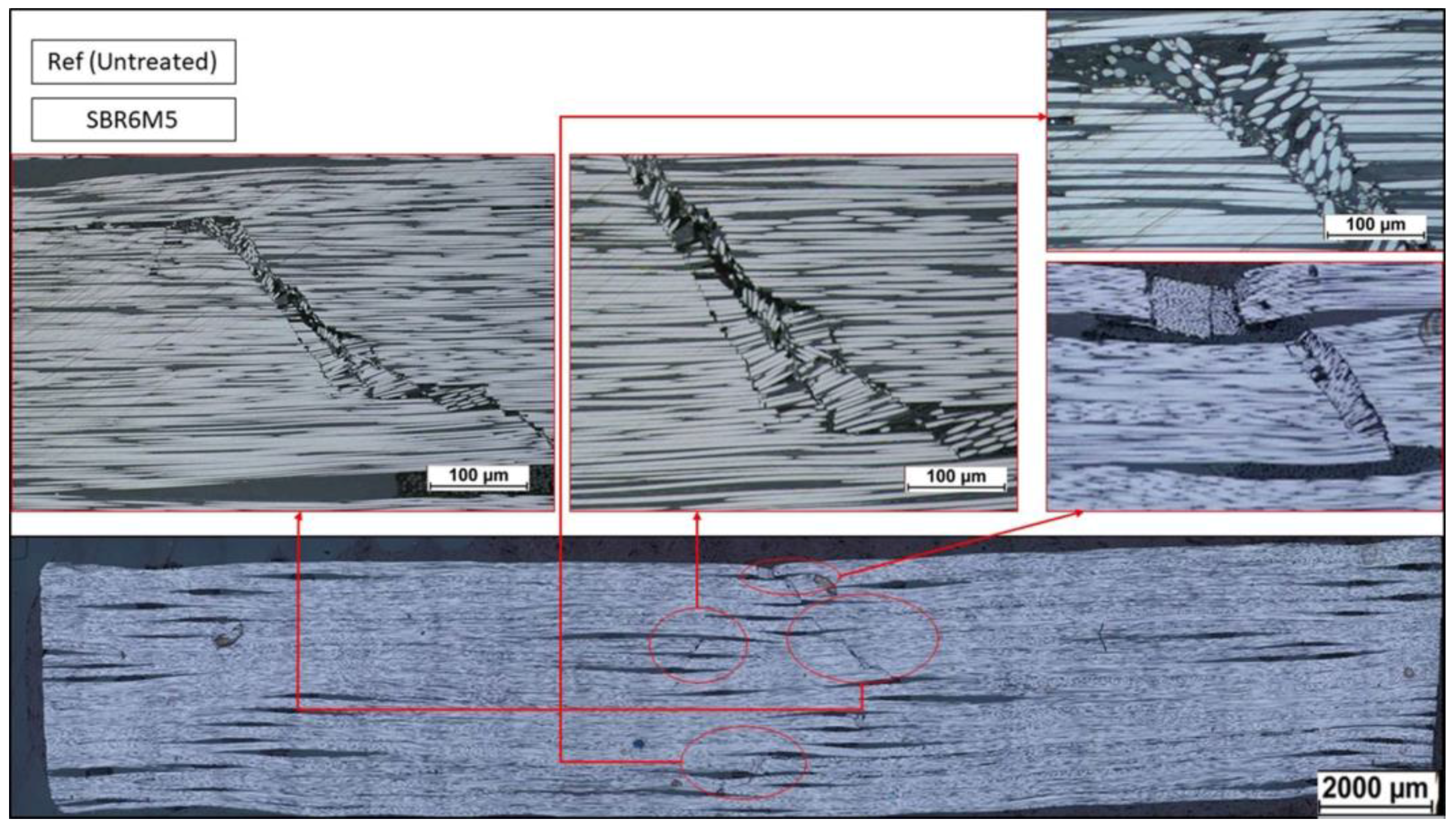
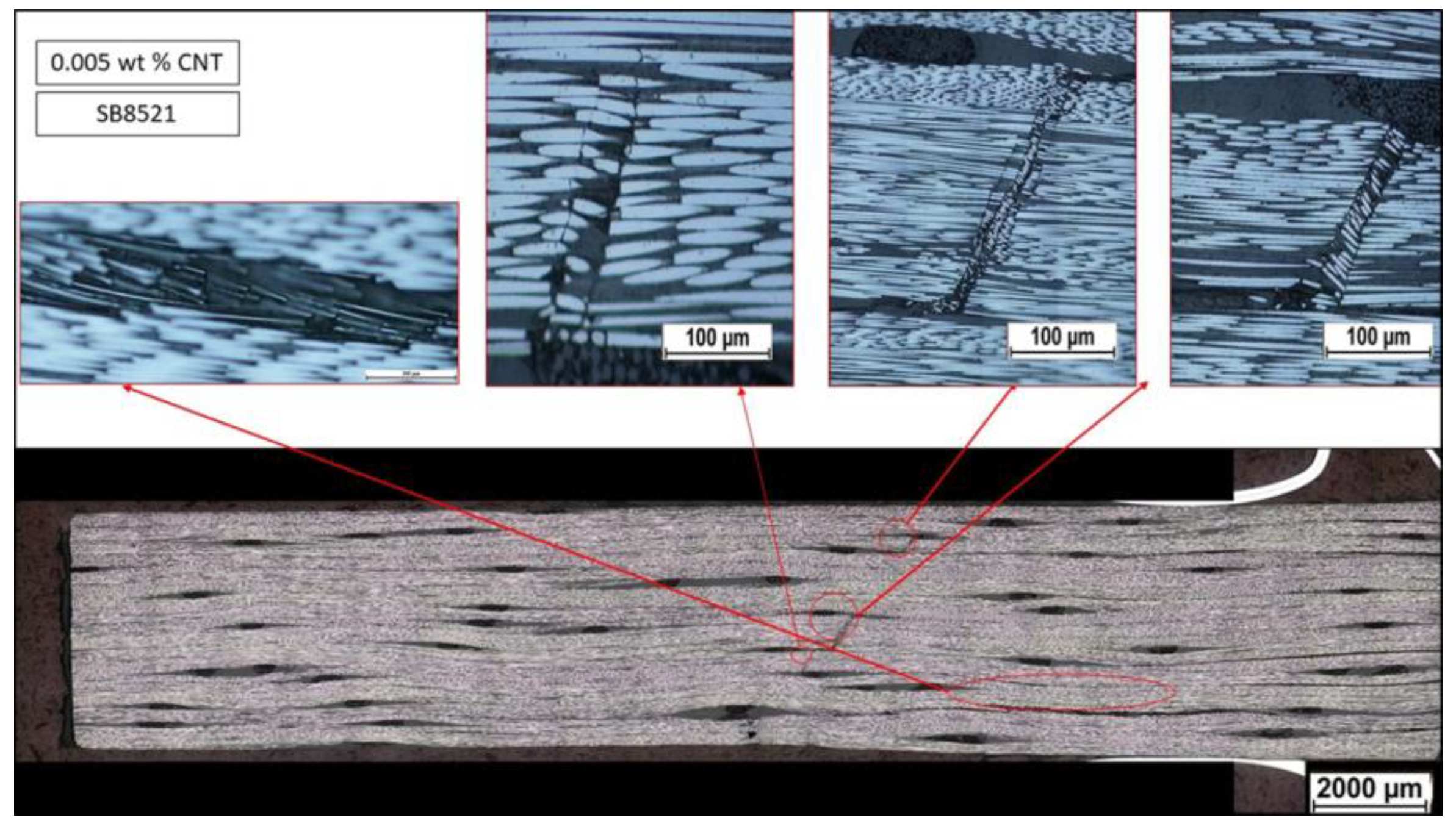
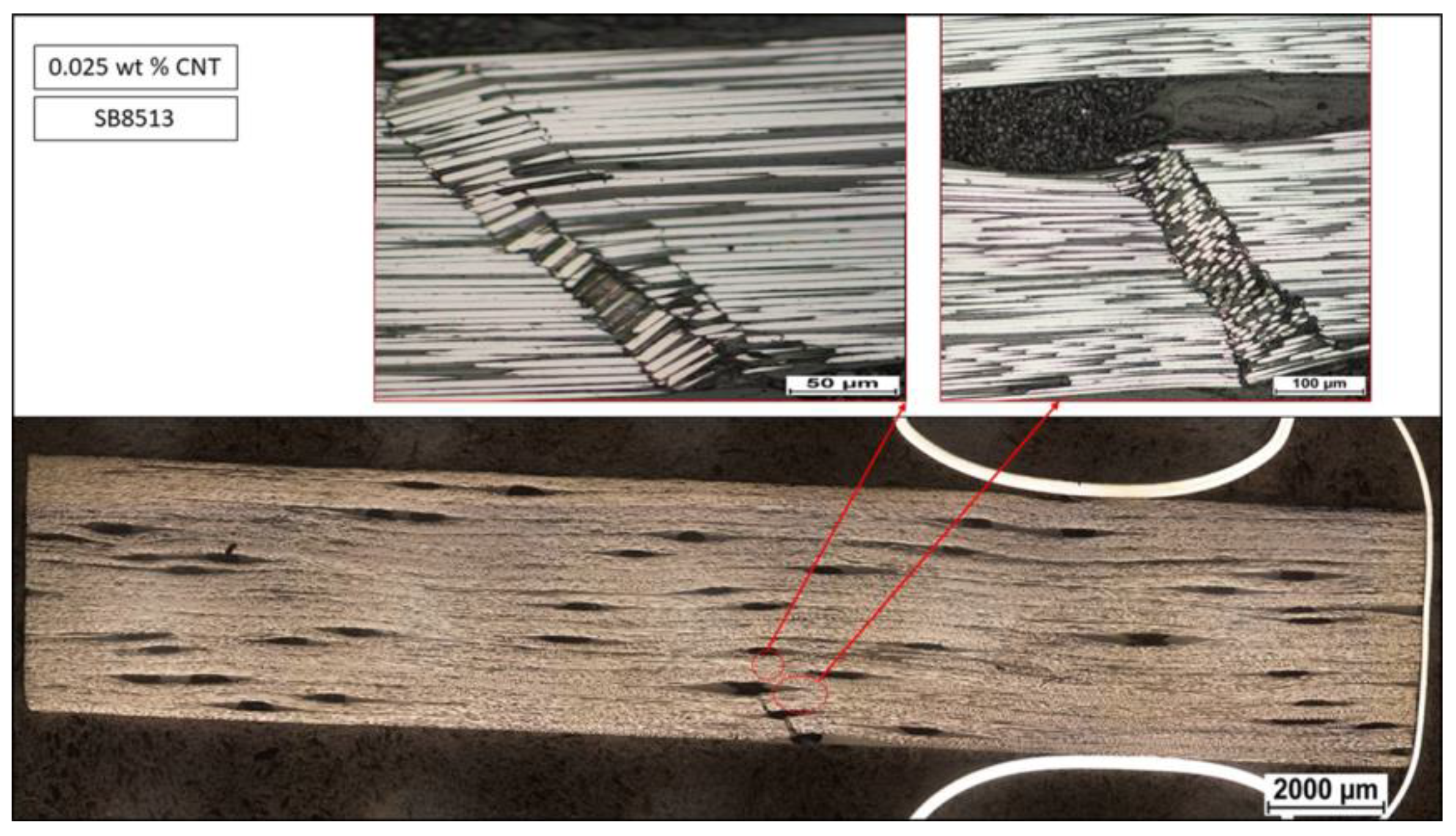
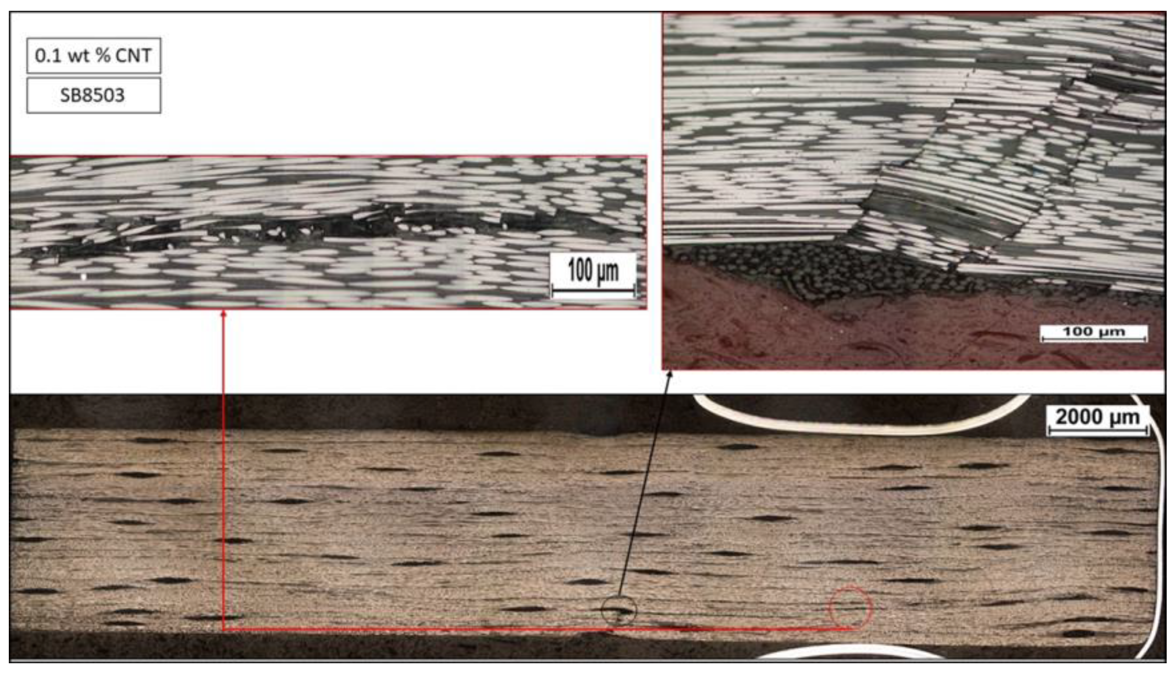
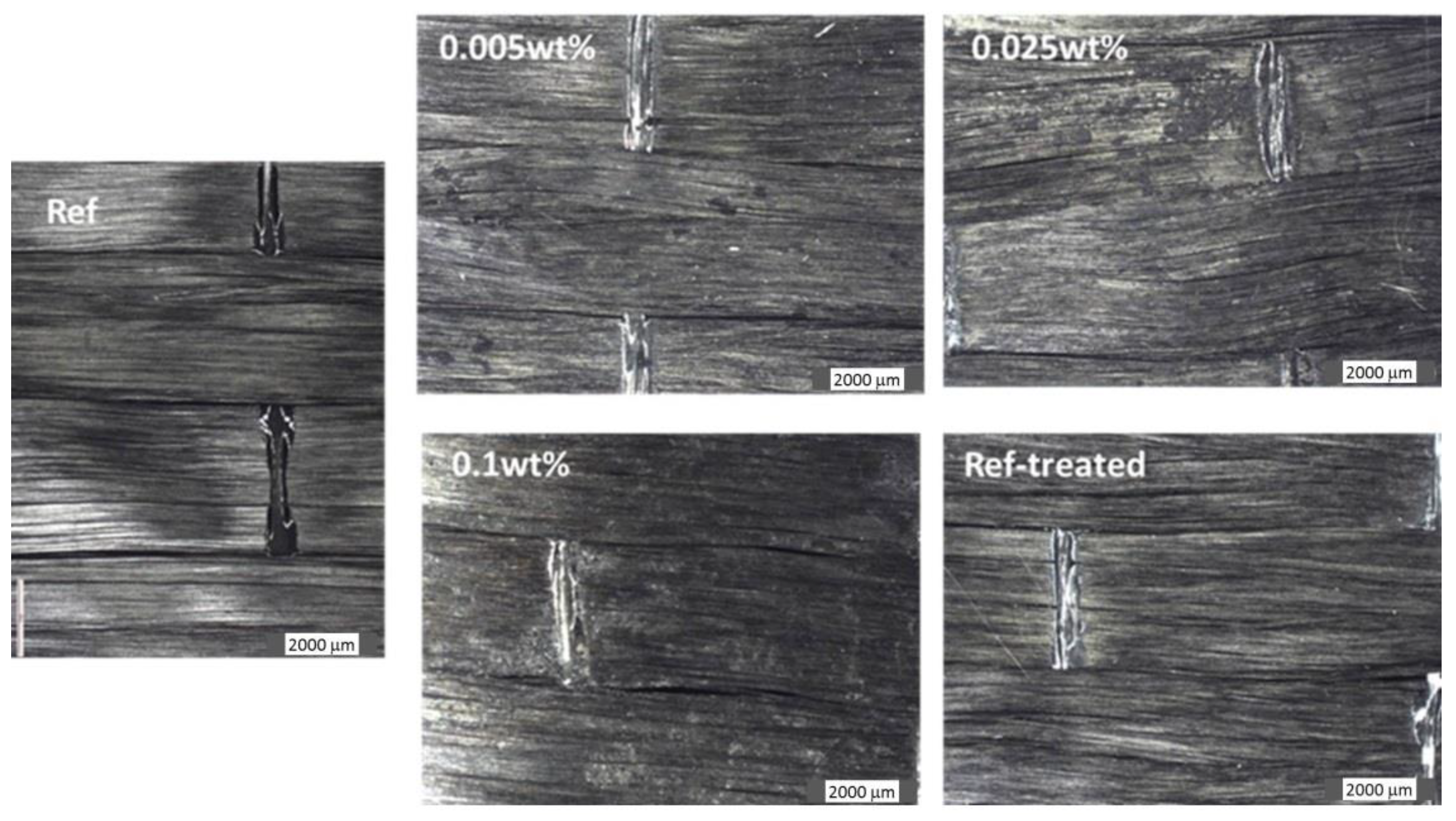
The results in Table 1 indicate no positive effect of the CNTs deposit on CF fabric on the mechanical performance of composites. As a matter of fact, there is a rather significant reduction of flexural stiffness and strength; ILSS is not enhanced either, which was not anticipated. The characterization of the microstructure of composites was carried out by means of optical microscopy in order to identify the problem. The microscopy images of short beam shear specimens after the test are shown in Figure 4, Figure 5, Figure 6 and Figure 7. The images clearly indicate that the failure mode present in those samples is fiber kinking, which occurs due to compressive stresses. Most often, the fiber micro-buckling which then forms kink bands under compression occurs due to geometrical defects in the materials, such as fiber waviness. The specimen overview micrographs show local fiber waviness all throughout the specimen, with more defects present in the composites reinforced with CNT-deposited CF fabrics than in the composite reinforced with pristine fabric. This has led to the conclusion that the CF fabric may be deformed during the wetting and drying process. The assumption is confirmed by the optical images of the different types of fabrics presented in Figure 8. It should be noted that one of the fabrics presented in Figure 8 is the water-treated fabric (named as “ref-treated”) that was obtained by pulling the pristine fabric (named as “ref”) through the water bath of the continuous EPD prototype without the addition of CNTs in the bath. As can be seen from the images in Figure 8, the fabrics after EPD treatment, regardless of the addition of CNTs in the bath, are indeed deformed and have much more waviness than the pristine (“ref”) fabric. The presence of local defects in the fabrics may have shadowed the positive effect of CNTs on the mechanical performance of composites, which may explain the unimpressive results presented in Table 1. In order to evaluate the effect of the deposit of CNTs more precisely, the composite reinforced with water-treated fabric was used as a reference (further in the text, it is named as a “treated reference composite”) for comparison to composites reinforced with CNT-deposited fabrics.
Table 2 summarizes the flexural properties and ILSS for the treated reference composite and the composites reinforced with CNT (Nanocyl)-deposited fabrics which were treated in the continuous EPD prototype without and with ultrasonication along the deposition process. Based on the results listed in Table 2, it is concluded that the deposition of CNTs onto the CF fabric via the continuous EPD process improves the flexural strength and stiffness and ILSS by 5–9% simultaneously. This is different from the common cases in which the improvement of some properties in composites with the addition of nanoparticles is usually at the cost of other properties, especially considering that the CNTs are not functionalized. Moreover, the use of ultrasonication during the continuous EPD process further increased the flexural properties of the composites reinforced with the CNT-deposited fabric significantly, while having a negligible influence on ILSS.

4. Conclusions

An EPD prototype was developed so that CNTs were deposited on carbon fiber fabrics continuously at a defined speed. Two critical factors for the deposition, strength of the electric field, and concentration of CNT aqueous suspension were optimized based on the dependence of deposition resistance upon the electric field, the potential water electrolysis and deposition quality. Since over 99.5 wt% of the CNT suspension is water, the CF fabric used in this study was deformed due to the wetting along the EPD and following drying process, resulting in much more waviness than pristine fabrics. In order to eliminate the effect of such defects on the following composite properties, the pristine fabric was also treated in the prototype following the same EPD procedure using demineralized water. Compared to the composite reinforced with such water-treated fabric, which in a sense is a fair comparison, the composite reinforced with CNT-deposited fabric using optimized deposition conditions showed simultaneously enhanced flexural strength and stiffness as well as interlaminar shear strength. Thus, the use of more geometrically stable fabrics would be advisable for future work. It is further noted that the enhancement of properties was achieved by using non-functionalized CNT and without removing the sizing on fibers, which is very different from the common cases. However, the proceeding time of the continuous EPD process is quite limited at the current stage because CNTs, regardless of functionalization or not, agglomerate with time under the electric field. Such agglomeration was speculated to occur due to the change of ionic density in the aqueous suspension or deposition of surfactant. Real-time monitoring and the adjustment of ionic density or surfactant amount in the EPD bath, or the use of organic solvent instead of water could be possible solutions; the trials are being carried out.

Author Contributions

G.G.: planning and supervision of project and technology development, manuscript writing; B.Y.: investigation, methodology development and manuscript writing; E.S. and D.E.: development and validation of EPD prototype; M.N.: processing of CNT-deposited carbon fiber fabrics and specification of experimental details Robert Westerlund: manufacturing of composites and specification of experimental details S.S., L.P. and A.P.: mechanical characterization and specification of experimental details R.J.: formal analysis, supervision and manuscript writing.

Funding

This research was funded by European Commission H2020 project, MODCOMP, grant number 685844.

Acknowledgments

The authors wish to thank exchange/project course students—Geoffrey Mesmin, Florian Bonnevay and Avnith Vignesh Eswaran from Luleå University of Technology for the help with experiments and optical microscopic study.

Conflicts of Interest

The authors declare no conflict of interest.

References

  1. Guadagno, L.; Raimondo, M.; Naddeo, C.; Di Bartolomeo, A.; Lafdi, K. Influence of multiwall carbon nanotubes on morphological and structural changes during UV irradiation of syndiotactic polypropylene films. J. Polym. Sci. Part B Polym. Phys. 2012, 50, 963–975. [Google Scholar] [CrossRef]
  2. Gorrasi, G.; Sarno, M.; Di Bartolomeo, A.; Sannino, D.; Ciambelli, P.; Vittoria, V. Incorporation of carbon nanotubes into polyethylene by high energy ball milling: morphology and physical properties. J. Polym. Sci. Part B Polym. Phys. 2007, 45, 597–606. [Google Scholar] [CrossRef]
  3. Thostenson, E.T.; Lim, W.Z.; Wang, D.Z.; Ren, Z.F.; Chou, T.W. Carbon nanotube/carbon fiber hybrid multiscale composite. J. Appl. Phys. 2002, 91, 6034–6037. [Google Scholar] [CrossRef]
  4. Huang, K.H.; Kuo, W.S.; Ko, T.H.; Tzeng, S.S.; Yan, C.F. Processing and tensile characterization of composites of carbon nanotube-grown carbon fibers. Compos. Part A Appl. Sci. Manuf. 2009, 40, 1299–1304. [Google Scholar] [CrossRef]
  5. Garcia, E.J.; Wardle, B.L.; Hart, A.J. Joining prepreg composite interfaces with aligned carbon nanotubes. Compos. Part A Appl. Sci. Manuf. 2008, 39, 1065–1070. [Google Scholar] [CrossRef]
  6. Veedu, V.P.; Cao, A.Y.; Li, X.S.; Ma, K.G.; Soldano, C.; Kar, S.; Ajayan, P.M.; Ghasemi-Nejhad, M.N. Multidinctional composites using reinforced laminae with carbon-nanotube forests. Nat. Mater. 2006, 5, 457–462. [Google Scholar] [CrossRef] [PubMed]
  7. Bekyarova, E.; Thostenson, E.T.; Yu, A.; Kim, H.; Gao, J.; Tang, J.; Hahn, H.T.; Chou, T.W.; Itkis, M.E.; Haddon, R.C. Multiscale carbon nanotube-carbon fiber reinforcement for advanced epoxy composites. Langmuir 2007, 23, 3970–3974. [Google Scholar] [CrossRef] [PubMed]
  8. Van der Biest, O.O.; Vandeperre, L.J. Electrophoretic deposition of materials. Annu. Rev. Mater. Sci. 1999, 29, 327–372. [Google Scholar] [CrossRef]
  9. Boccaccini, A.R.; Cho, J.; Roether, J.A.; Thomas, B.J.C.; Minay, E.J.; Shaffer, M.S.P. Electrophoretic deposition of carbon nanotubes. Carbon 2006, 44, 3149–3160. [Google Scholar] [CrossRef]
  10. Santhanagopalan, S.; Balram, A.; Lucas, E.; Marcano, F.; Meng, D.D. High voltage electrophoretic deposition of aligned nanoforests for scalable nanomanufacturing of electrochemical energy storage devices. Key Eng. Mater. 2012, 507, 67–72. [Google Scholar] [CrossRef]
  11. Deng, C.; Jiang, J.; Liu, F.; Fang, L.; Wang, J.; Li, D.; Wu, J. Influence of graphene oxide coatings on carbon fiber by ultrasonically assisted electrophoretic depostion on its composite interfacial property. Surf. Coat Technol. 2015, 272, 176–181. [Google Scholar] [CrossRef]
  12. Deng, C.; Jiang, J.; Liu, F.; Fang, L.; Wang, J.; Li, D.; Wu, J. Effects of electrophoretically deposited graphene oxide coatings on interfacial properties of carbon fiber composite. J. Mater. Sci. 2015, 50, 5886–5892. [Google Scholar] [CrossRef]
  13. Liang, S.; Li, Q.; Wang, J.; He, Z.; Zhao, Y.; Kang, M. Multiscale graphene oxide-carbon fiber reinforcements for advanced polyurethane composites. Compos. Part A Appl. Sci. Manuf. 2016, 87, 1–9. [Google Scholar]
  14. Wang, C.; Li, J.; Sun, S.; Li, X.; Zhao, F.; Jiang, B.; Huang, Y. Electrophoretic deposition of graphene oxide on continuous carbon fibers for reinforcement of both tensile and interfacial strength. Compos. Sci. Technol. 2016, 135, 46–53. [Google Scholar] [CrossRef]
  15. ASTM. D7264/D7264M-15 Standard Test Method for Flexural Properties of Polymer Matrix Composite Materials; ASTM International: West Conshohocken, PA, USA, 2015. [Google Scholar]
  16. ASTM. D2344/D2344M-16 Standard Test Method for Short-Beam Strength of Polymer Matrix Composite Materials and Their Laminates; ASTM International: West Conshohocken, PA, USA, 2016. [Google Scholar]
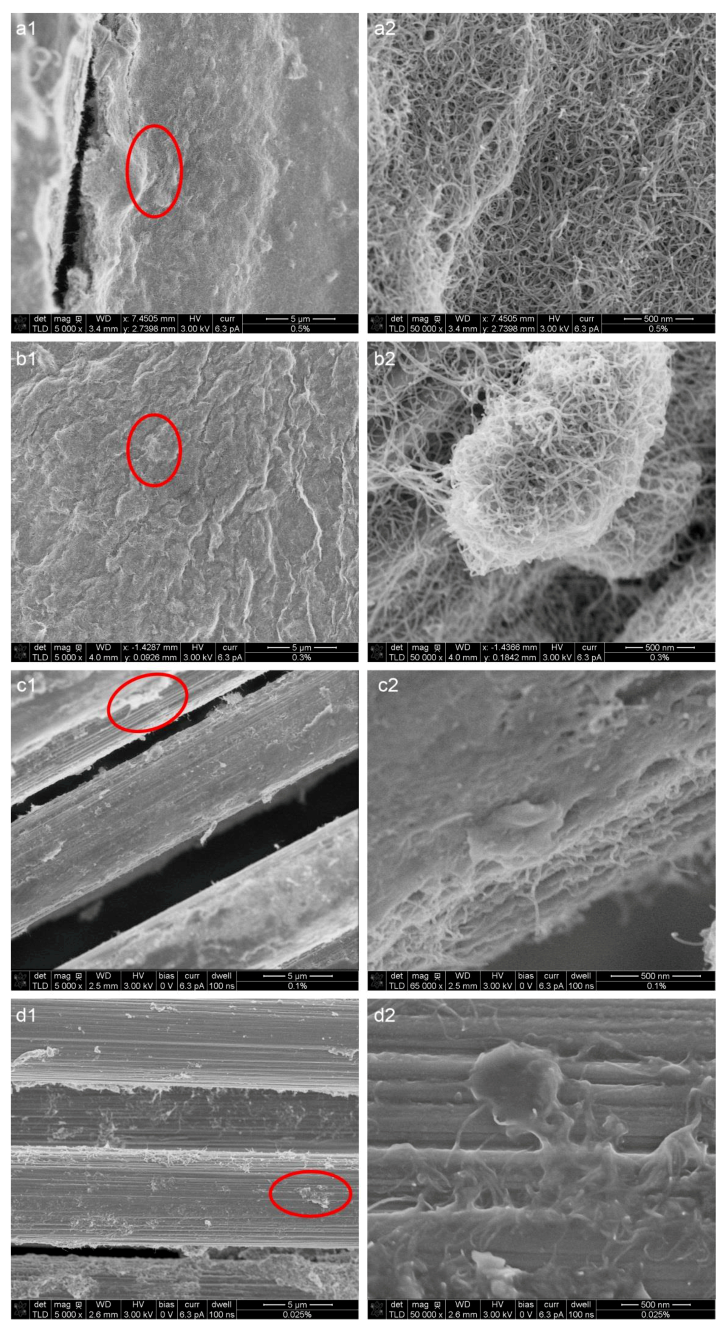
Figure 1. SEM images of deposited carbon nanotube (CNT) on carbon fiber (CF) fabrics using (a) 0.5 wt% Nanocyl suspension, (b) 0.3 wt% Nanocyl suspension, (c) 0.1 wt% Nanocyl suspension, and (d) 0.025 wt% Nanocyl suspension, at an electric field 10 V/cm and deposition time of three min for each spot on the fabric. (a2d2) are zoomed-in images with respect to the red-ring marked region in image of (a1d1), correspondingly.
Fibers 06 00071 g001
Figure 2. Appearance of chunks of CNT agglomerates in Nanocyl suspension (left) and Nanolab suspension (right) after three hours of deposition; suspensions were taken from the electrophoretic deposition (EPD) bath and placed on a 100-mm diameter disc for better observation and photographs.
Fibers 06 00071 g002
Figure 3. Evolution of pH value with time in the continuous EPD process for CNT suspension diluted from Nanolab product (left) and Nanocyl product (right).
Fibers 06 00071 g003
Figure 4. Micrograph of reference composite (composite reinforced with pristine CF fabric) short beam shear specimen after the test. The (Bottom) image shows an overview of the part of the specimen. (Upper) images indicate the fiber kinking that was formed during the failure.
Fibers 06 00071 g004
Figure 5. Micrograph of composite reinforced with 0.005 wt% CNT suspension-treated CF fabric short beam shear specimen after the test. The (Bottom) image shows an overview of the part of the specimen. (Upper) images indicate the fiber kinking that was formed during the failure.
Fibers 06 00071 g005
Figure 6. Micrograph of composite reinforced with 0.025 wt% CNT suspension-treated CF fabric short beam shear specimen after the test. The (Bottom) image shows an overview of the part of the specimen. The (Upper) images indicate the fiber kinking that was formed during the failure.
Fibers 06 00071 g006
Figure 7. Micrograph of 0.1 wt% CNT suspension-treated CF fabric short beam shear specimen after the test. The (Bottom) image shows an overview of the part of the specimen. The (Upper) images indicate the fiber kinking formed during the failure.
Fibers 06 00071 g007
Figure 8. Optical images of the pristine (Ref) fabric compared to the water-treated (Ref-treated) and CNT suspension-treated fabrics.
Fibers 06 00071 g008
Table 1. Flexural properties and interlaminar shear strength of composites reinforced with pristine CF fabric and CNT-deposited CF fabric (ultrasonication was not used during the continuous EPD process).
Material/PropertiesEb/GPaσb/MPaεb/%FSBS/MPa
Composite reinforced with pristine CF fabric114.4 ± 1.81199.6 ± 65.21.1 ± 0.165.2 ± 2.7
Composite reinforced with 0.005 wt%
CNT suspension-treated CF fabric
110.0 ± 6.4923.5 ± 104.20.8 ± 0.261.5 ± 1.9
Composite reinforced with 0.025 wt%
CNT suspension-treated CF fabric
97.9 ± 2.8713.5 ± 46.40.7 ± 0.165.6 ± 1.3
Composite reinforced with 0.1 wt%
CNT suspension-treated CF fabric
93.5 ± 1.6726.3 ± 83.00.8 ± 0.155.2 ± 2.4
Eb—bending stiffness, σb—flexural strength, εb—strain at failure, FSBS—interlaminar shear strength (ILSS).
Table 2. Flexural properties and interlaminar shear strength of treated reference composite and composites reinforced with CNT-deposited CF fabric with and without ultrasonication being used during the continuous EPD process.
Material/PropertiesEb/GPaσb/MPaεb/%FSBS/MPa
Treated reference composite104.7 ± 1.3872.1 ± 90.60.9 ± 0.160.9 ± 3.5
Composite reinforced with deposited fabric using 0.025 wt% CNT suspension and no ultrasonication97.9 ± 2.8713.5 ± 46.40.7 ± 0.165.6 ± 1.3
Composite reinforced with deposited fabric using 0.025 wt% CNT suspension and with ultrasonication106.1 ± 2.2838.5 ± 70.70.8 ± 0.165.0 ± 2.4
Composite reinforced with deposited fabric using 0.005 wt% CNT suspension and no ultrasonication110.0 ± 6.4923.5 ± 104.20.8 ± 0.261.5 ± 1.9
Composite reinforced with deposited fabric using 0.005 wt% CNT suspension and with ultrasonication108.3 ± 3.8950.2 ± 90.40.9 ± 0.262.1 ± 1.0