
Article

Fracture Behavior Under Mode I Loading in Laminated Composite Materials Repaired with Structural Adhesives

1
Department of Construction and Manufacturing Engineering, University of Oviedo, Edificio Departamental Oeste, 33203 Gijón, Spain
2
Department of Materials Science and Metallurgical Engineering, University of Oviedo, Edificio Departamental Este, 33203 Gijón, Spain
*
Author to whom correspondence should be addressed.
Fibers 2026, 14(2), 20; https://doi.org/10.3390/fib14020020
Submission received: 22 December 2025 / Revised: 12 January 2026 / Accepted: 29 January 2026 / Published: 2 February 2026
(This article belongs to the Topic Advanced Composite Materials)

Highlights

What are the main findings?
  • Adhesive-based repair partially restores the Mode I fracture performance of previously delaminated CFRP laminates, reaching values comparable to the baseline material.
  • The laminate with a modified epoxy matrix (AS4/8552) shows significantly higher fracture toughness than the unmodified epoxy system (AS4/3501-6), even after adhesive-based repair.
What are the implications of the main findings?
  • Repair effectiveness strongly depends on the mechanical behaviour and ductility of the adhesive, with acrylic adhesives providing enhanced energy dissipation and more stable crack propagation under Mode I loading.
  • Adhesive selection for composite repair should prioritize energy dissipation capability rather than stiffness alone, especially for damage scenarios dominated by Mode I.

Abstract

One of the most critical damage modes affecting the structural performance of traditional composite materials, and therefore their durability, is the occurrence of interlaminar cracks (delamination), which are prone to grow under different loading conditions. In this study, the feasibility of repairing carbon fiber reinforced polymer (CFRP) laminates using structural adhesives was experimentally investigated by evaluating the Mode I interlaminar fracture toughness. Two unidirectional AS4 CFRP systems were analyzed, manufactured with epoxy 8552 and epoxy 3501-6 matrix resins. Mode I delamination behavior was characterized using Double Cantilever Beam (DCB) specimens. Three commercial structural adhesives were used in the repair process: two epoxy-based systems, (Loctite® EA 9460™, manufactured by Henkel adhesives (Düsseldorf, Germany), and Araldite® 2015 manufactured by Huntsman Advanced Materials (The Woodlands, TX, USA) and one low-odor acrylic adhesive, 3M Scotch-Weld® DP8810NS manufactured by 3M Company (St. Paul, MN, USA). Adhesive joints were applied to previously fractured specimens, and the results were compared with those obtained from baseline composite specimens. The results indicate that repaired joints based on the 8552 matrix exhibited higher strain energy release rate (GIc) values, approaching those of the original material. The 3501-6 system showed increased fiber bridging, contributing to higher apparent fracture toughness. Among the adhesives evaluated, the acrylic-based adhesive provided the highest delamination resistance for both composite systems.

1. Introduction

Delamination failure in laminated composite materials is particularly relevant in applications where high levels of loading, reliability, and safety are required. The relationship between the generated damage, delamination and the associated stress state is a key parameter to consider when designing components made of these materials. From an experimental point, fracture mechanics is the tool most widely used to predict their behavior. Numerous studies have been developed and continue to be carried out in this field, covering all fracture modes, with the aim of quantifying in-service behavior while also providing practical data for the design of parts and components [1,2,3,4,5,6,7,8,9,10].
One of the parameters associated with delamination processes is the influence of the matrix on the material behavior [11]. Tests on different materials have shown that the relationship between the toughness of the matrix and that of the laminate is nonlinear [12]. The ratio between the Mode I fracture toughness of the composite and that of the matrix is slightly greater than unity for brittle matrices, mainly thermosets, and significantly lower than unity for ductile matrices, mainly thermoplastics.
Other experimental and analytical studies have highlighted the need to restrict the matrix surfaces in order to make accurate predictions of composite toughness. These studies indicate that the toughness of the matrix constrained by boundary conditions, obtained using an extremely thin resin film as an adhesive layer, is similar to the toughness of the composite material [13].
To determine the influence of the adhesive on fracture toughness, several investigations have analyzed the effect of adhesive thickness. These studies showed a clear relationship between increasing fracture energy and increasing adhesive thickness. This trend continued until the adhesive thickness reached approximately 1 mm, above which the fracture energy remained stable. Additional studies on rubber-like adhesives concluded that fracture energy increases as the adhesive layer thickness increases, while the initial stiffness increases as the adhesive layer thickness decreases. Furthermore, in the case of epoxy adhesives, fracture toughness was found to increase continuously with adhesive thickness up to approximately 1.3 mm, remaining nearly constant for larger bond-line thicknesses [14,15,16].
The main conclusion drawn from the literature is that matrix behavior can be used to understand deformation mechanisms in composite materials. However, it remains difficult to quantitatively predict laminate properties solely from matrix properties.
When addressing the issue of composite recycling it must be noted that one of the main drawbacks of these materials is their limited recyclability [17,18,19]. Due to their heterogeneous nature and very different properties, most composites, particularly those with thermoset matrices, cannot be remelted without material degradation [20]. Considering the rapidly increasing global demand for carbon fiber reinforced composites (CFRPs), continued growth in their use is expected [21]. The annual generation of CFRP waste in Europe and the United States has been estimated to be approximately 3000 tons [22]. This situation has become a major environmental concern, since traditional approaches for managing composite waste are largely limited to landfilling and incineration.
Projections indicate that by 2030, between 6000 and 8000 commercial aircraft are expected to reach the end of their service life [23]. Although research activity in this field remains limited [24,25,26], new recycling technologies are emerging, mainly based on mechanical, thermal, and chemical methods. In mechanical recycling processes, composites are crushed into particles ranging from approximately 10 mm to 50 µm, which are subsequently used as fillers for lower-grade composite materials.
Pyrolysis is the most widely used thermal recycling method. In this process, the polymeric matrix is decomposed and converted into lower-molecular-weight components. However, the high temperatures involved can lead to fiber degradation. In some cases, recycled carbon fibers produced by pyrolysis retain up to 90% of their original tensile strength, while their elastic modulus remains essentially unchanged. In contrast, recent studies have shown that chemical recycling methods are a promising alternative, allowing the recovery of clean fibers with purities of up to 99.9%. Nevertheless, many of these processes are aggressive and may degrade the fibers, leading to a reduction in their mechanical properties. Examples of chemical recycling approaches include atmospheric pressure depolymerization using benzyl alcohol and K3PO4 at 200 °C, as well as acid digestion using acetic acid and H2O2 at 110 °C [21].
Regarding adhesive properties [27,28,29,30,31,32,33], thermosetting epoxy adhesives are the most widely used in structural bonding applications. These adhesives are based on epoxide functional groups and are commercially available as one- or two-component systems. One-component adhesives require heat activation for curing, whereas two-component systems consist of a resin (diepoxide or polyepoxide) and a hardener (polyamines or mercaptans). Epoxy adhesives provide strong joints and are generally very stiff, ranking among the best-performing commercial adhesives. In general, they offer good thermal resistance, although they are difficult to process and recycle.
Acrylic adhesives, in contrast, are thermoplastic materials. They provide strong structural bonds and fast curing at room temperature, typically with good environmental resistance. However, their curing depth is limited to approximately 1 mm, and the activator may contain solvents that can damage the substrate. These adhesives are often used to bond materials with different characteristics. Table 1 provides a basic comparison of their main features.
These findings provide valuable insights for the design and selection of adhesive-based repair strategies in composite structures, particularly in high-value applications such as aerospace components and structural maintenance.
Regarding the response of these adhesives to the delamination process, comparative studies have evaluated epoxy and acrylic based adhesives under Mode I fracture using DCB specimens [34]. In addition, their mechanical properties were characterized through different experimental tests, including tensile and torsion tests. The results showed that the strength of joints bonded with epoxy adhesives was approximately four times higher than that of joints bonded with acrylic adhesives, regardless of the joint configuration. However, the strain at the failure point of the acrylic adhesive was found to be approximately ten times higher than that of the epoxy adhesive.
In line with this research framework related to the recycling of composite materials, the aim of the present work is to investigate the feasibility of composite repair processes using adhesive bonding. To this end, adhesive joints were manufactured on specimens previously tested under Mode I fracture loading, and the results obtained were compared with those corresponding to the original (as-received) material, as well as with joints manufactured on laminates specifically produced for bonding purposes. Two composite materials were analyzed, both reinforced with unidirectional carbon fibers, but employing two different epoxy matrices: one exhibiting tough behavior and the other a brittle behavior.

2. Materials and Methods

2.1. Materials and Specimens

The experimental work was carried out on two composite materials manufactured with the same AS4 unidirectional carbon reinforcement. Both materials employed epoxy resins from the same manufacturer: one material used a modified epoxy resin (type 8552) with the commercial designation Hexply® AS4/8552 RC34 AW196, while the other employed an unmodified epoxy resin (type 3501-6) with the commercial designation Hexply® AS4/3501-6 RC37 AW190. All base materials were supplied by Hexcel Corporation (Stamford, CT, USA). The mechanical properties of these materials are summarized in Table 2 and correspond to values obtained from a previous experimental characterization of the carbon fiber composite materials carried out in the laboratory.
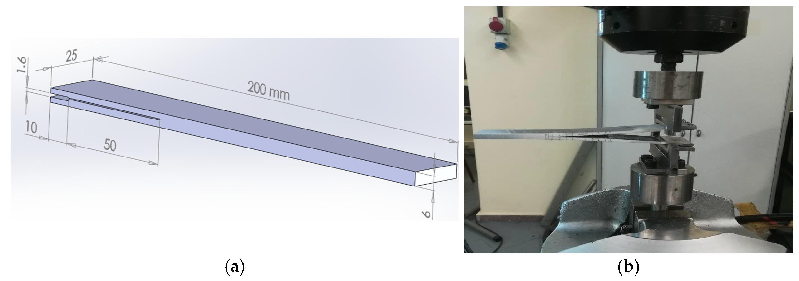
For the characterization of delamination under Mode I in both materials, whether in monolithic laminated specimens or in those manufactured by bonding, the same specimen configuration was used for monolithic laminated specimens and bonded specimens (Figure 1), in accordance with ASTM D5528 [35]. The specimens had a rectangular geometry with uniform thickness and width and consisted of an even number of unidirectional plies. A non-adhesive insert (Tygavac RF 242, supplied by Airtech Advanced Materials Group (Huntington Beach, CA, USA), 12 μm thick) was placed at the mid-plane at one end of the specimen, with a length of 60 mm, to facilitate the initiation of delamination.
For the fabrication of specimens from previously fractured samples, considered in this study as repaired specimens, the procedure described below was followed. The bonding surfaces were abraded using fine grit P220 sandpaper supplied by Buehler (Lake Bluff, IL, USA), subsequently cleaned with acetone, and bonded using the corresponding adhesive. Prior to curing, the specimens were subjected to vacuum, after which the excess material along the sides was machined. Finally, the surface was painted and marked to allow monitoring of crack growth during the tests.
In order to eliminate any influence of environmental conditions on the tests, all specimens were subjected to prior drying.
All tests were carried out on an MTS 810 servo-hydraulic testing machine with load cell 1 kN. Mechanical grips were used to hold the specimen in the testing machine instead of hinges.
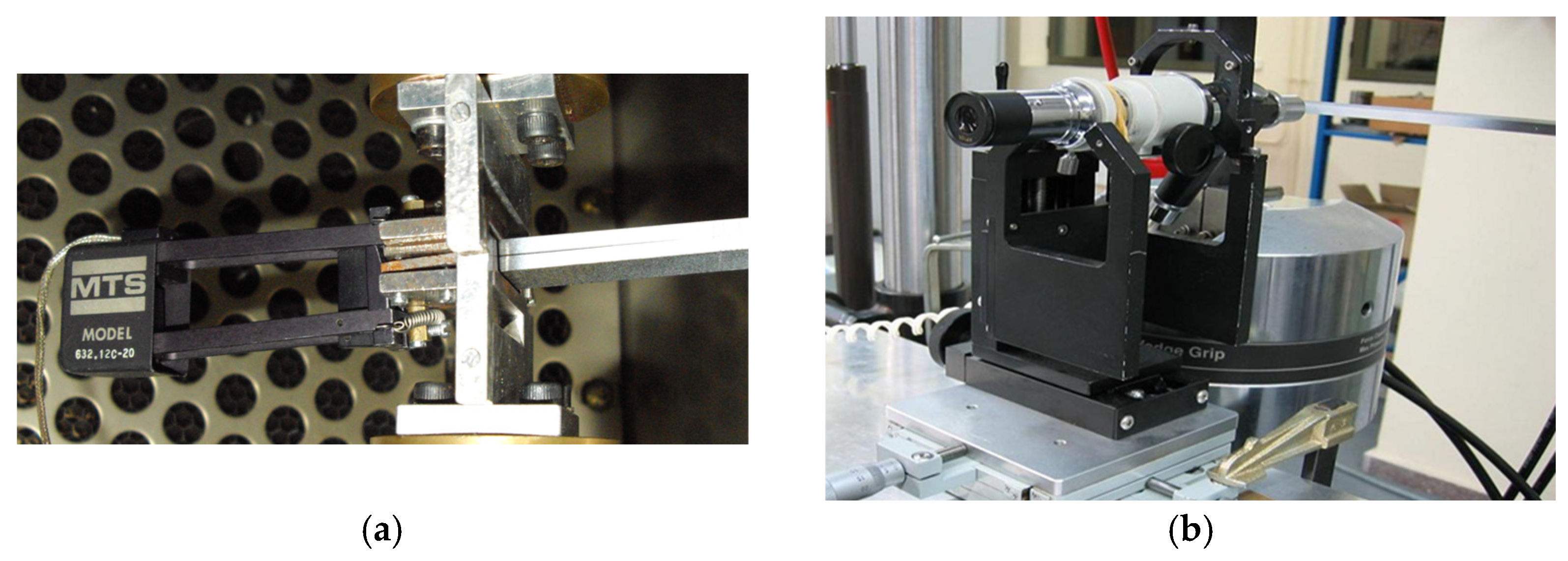
A total of 18 specimens per material system were manufactured and tested for each bonded joint configuration. For each adhesive system, 6 specimens were prepared and tested on AS4/8552 laminates and six specimens on AS4/3501-6 laminates, resulting in 12 specimens per adhesive. Consequently, 12 specimens bonded with Loctite® EA 9461™, 12 with Araldite® 2015, and 12 with 3M™ Scotch-Weld™ DP8810NS were experimentally evaluated. In addition, to establish reference behavior, 18 baseline (unbonded) specimens were tested for each composite material, namely AS4/8552 and AS4/3501-6. Therefore, the experimental campaign comprised a total of 72 bonded specimens and 36 baseline specimens, ensuring statistical consistency across all material adhesive combinations. Figure 2 shows the extensometer and the experimental setup and the optical microscope used during the tests.

2.2. Adhesives

This section is devoted to describing the characteristics of the adhesives used in this work. Two epoxy-based adhesives (matching the substrate) and one acrylic adhesive were employed. All of them are widely used in structural applications, particularly epoxy adhesives, which are the most common when working with composite materials. The adhesives used were: 3M™ Scotch-Weld™ DP8810NS, an acrylic-based adhesive cured at room temperature; Araldite® 2015, an epoxy-based adhesive; and Loctite® EA 9461™ (also epoxy-based). The curing process for each adhesive differed and was carried out in accordance with the specifications provided by the respective manufacturers. The basic properties of the adhesives, as reported by the manufacturers, are summarized in Table 3.
The thickness of the adhesives was measured on 3 different specimens of each of them. It was carried out with a ZEISS magnifying glass, model Stemi 508, equipped with an Axiocam 208 Color camera, both supplied by Carl Zeiss Microscopy (Jena, Germany), with a magnification between 3.2× and 5×. The average values were 0.278 mm for Loctite epoxy adhesive, 0.255 mm for Araldite epoxy adhesive and 0.215 mm for acrylic based adhesive.

2.3. Static Fracture Toughness

To determine the fracture toughness of both materials under static loading and Mode I fracture, ASTM D5528 was followed. The fracture toughness calculations were carried out using the three methods proposed by this standard: the Modified Beam Theory (MBT), the Compliance Calibration method (CC), and the Modified Compliance Calibration method (MCC).
Modified Beam Theory (MBT)
GIC = 3Pδ/(2b(a + ∣Δ∣))
Compliance Calibration (CC)
GIC = nPδ/2ba
Modified Compliance Calibration (MCC)
GIC = 3P2·C2/3/2A1bh
where b is the specimen width, h the specimen thickness, P the applied load, δ the displacement at the load application point, a delamination length, and Δ is a correction factor obtained as a function of the compliance C and the crack length. The parameter n is determined from the slope of the linear fit of log(C) versus log(a). To obtain parameter A1, the experimental curve of a/h versus C1/3 must be constructed, where A1 corresponds to the slope of the least-squares fitted line.
A test speed of 1 mm/min was maintained. Crack initiation was identified through direct observation of the specimen using a 70× microscope and verified by means of a clip-on extensometer placed at the specimen front.

3. Results and Discussion

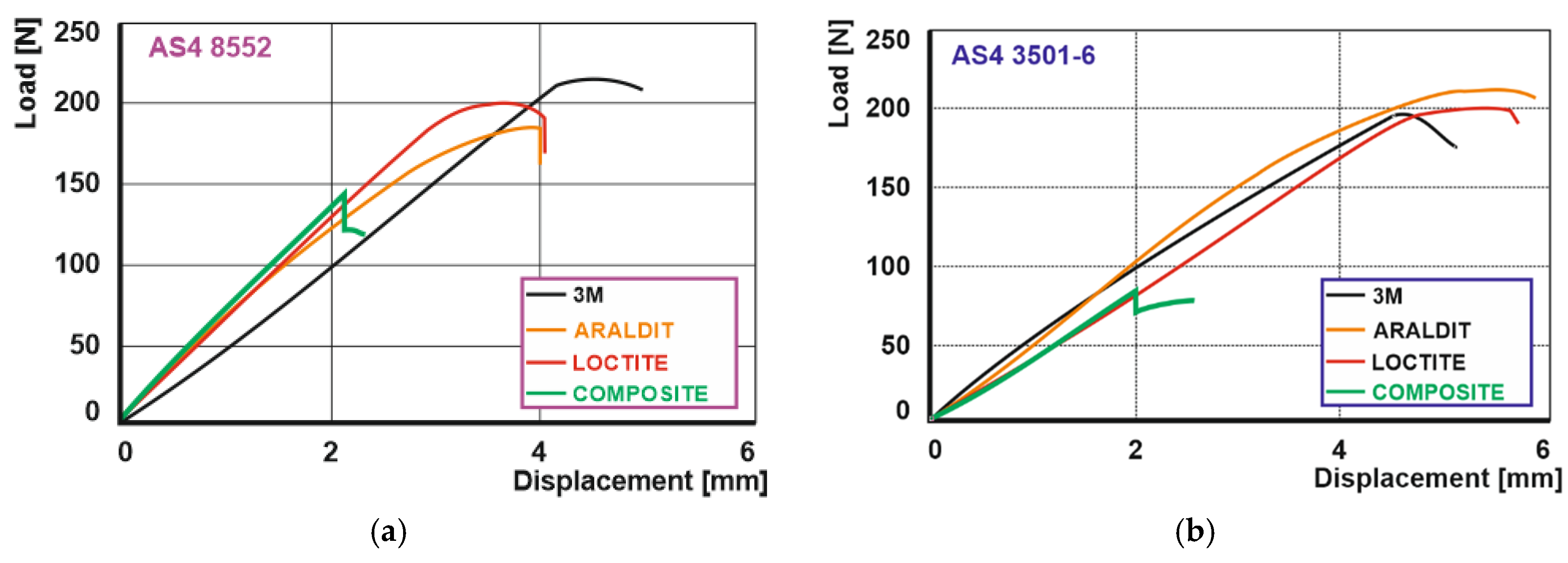
The following section presents the experimental results obtained from the static tests, corresponding to the specimens described in Section 2. Figure 3 illustrates the load–displacement curves recorded during the crack initiation phase for both materials and for each adhesive system investigated. The term “composite” refers to the baseline laminated material tested without any adhesive layer.
Figure 3 shows a similar overall behaviour for both materials, although with some noticeable differences. In both cases, the baseline composite exhibits significantly lower delamination initiation loads compared to those obtained for the specimens repaired with the different adhesive systems.
The slopes of the load–displacement curves are mainly governed by the stiffness of the AS4/8552 resin system, resulting in slopes comparable to those observed for both epoxy-based adhesives. For adhesive joints manufactured on AS4/8552 composite substrates, a higher deformation capacity than that of the baseline material is observed. Specifically, the load-point displacements nearly doubled, with similar deformation levels for the two epoxy-based adhesives and a slightly higher displacement for the acrylic-based adhesive.
In the case of the AS4/3501-6 composite, the three adhesive systems exhibit a more uniform response, with very similar load–displacement behaviour. This trend can be attributed to the lower deformation capacity of the substrate, as it corresponds to a more brittle matrix composite, which may partially limit the deformation capability of the adhesive layer. The response of the two epoxy-based adhesives is practically identical, while no significant differences are observed for the acrylic adhesive.
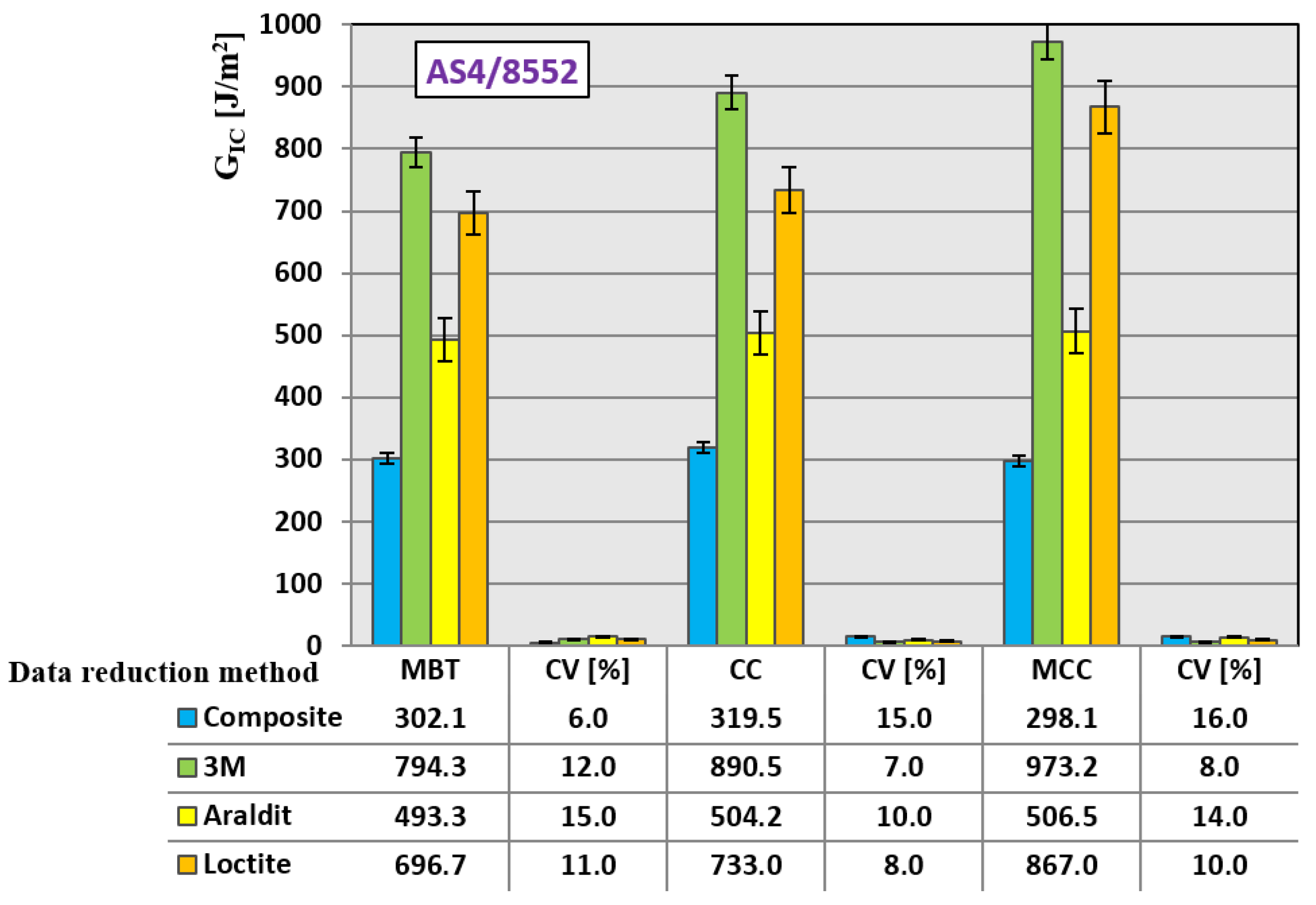
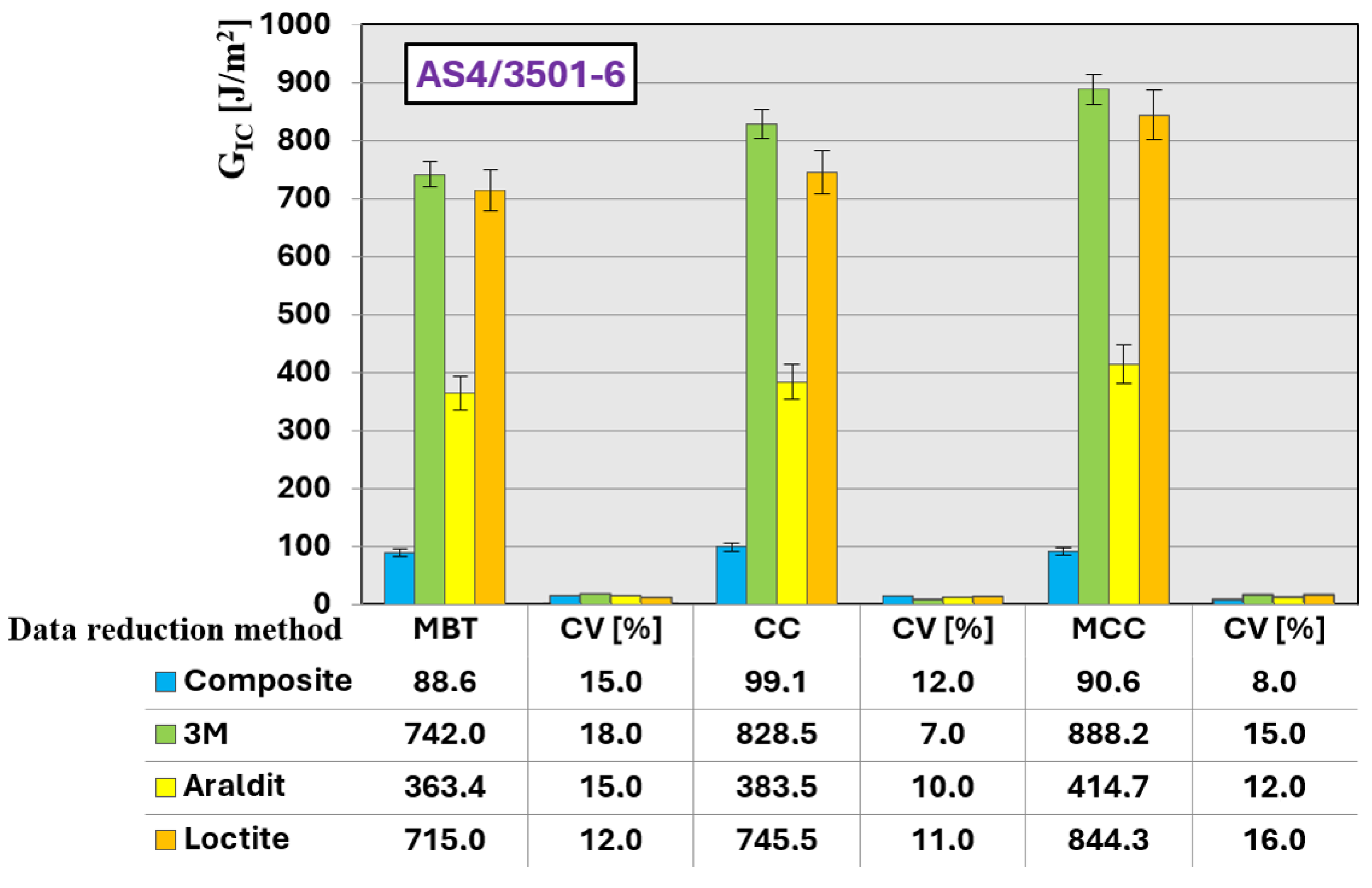
Figure 4 and Figure 5 present the results of the static characterization in terms of critical fracture energy, calculated at the maximum load point using the three methods specified in the standard: Modified Beam Theory (MBT), Compliance Calibration (CC), and Modified Compliance Calibration (MCC). Figure 4 corresponds to the AS4/8552 material, whereas Figure 5 corresponds to AS4/3501-6.
A direct comparison between joints manufactured on previously delaminated substrates (repaired specimens) and the corresponding baseline composite specimens revealed no significant differences in the measured Mode I fracture toughness. For a given adhesive system and composite material, the GIc values obtained for repaired joints were comparable to those measured for newly bonded specimens, indicating that the adhesive layer governs the fracture response regardless of the substrate condition. These results suggest that the presence of a pre-existing delamination does not adversely affect the effectiveness of the adhesive-based repair under Mode I loading conditions.
At the substrate level, the modified epoxy resin system (8552) exhibited consistently superior performance, achieving fracture toughness values significantly higher than those obtained for the unmodified resin (3501-6). On average, the fracture toughness of the AS4/8552 laminate was approximately three times greater than that of AS4/3501-6. In addition, the calculation method used to determine the fracture toughness did not significantly influence the overall trends observed.
Nevertheless, slight differences among the data reduction methods can be identified. The Compliance Calibration (CC) method systematically yielded higher fracture toughness values than those obtained using the Modified Beam Theory (MBT) and the Modified Compliance Calibration (MCC) methods, which provided nearly coincident results. Under static loading conditions, the fracture energy calculated using the CC method was 5.6% higher for the AS4/8552 laminate and 9.9% higher for the AS4/3501-6 laminate.
Regarding the behaviour of the adhesive systems employed in the repair process, it was observed that, irrespective of the calculation method, the acrylic-based adhesive exhibits a lower critical fracture energy (GIc) compared to the epoxy-based systems. However, its more ductile behaviour promotes plastic deformation within the adhesive layer, leading to a more progressive crack initiation and a more controlled crack propagation. This behavior can be explained by the higher degree of ductility of the adhesives studied when compared to the matrix materials of the composite substrates. The differences between the acrylic 3M adhesive and the epoxy-based Loctite adhesive were relatively small. Among the epoxy adhesives analysed, the Araldite system exhibited the lowest fracture toughness values.
With respect to the influence of the substrate, the AS4/3501-6 laminate consistently showed a lower resistance to delamination, regardless of the adhesive used for repair, highlighting the dominant role of the substrate properties in the fracture response.
From a quantitative standpoint, and focusing on the conservative MBT data reduction method, the acrylic-based adhesive (3M™ Scotch-Weld™ DP8810NS) provided GIc values that were comparable to, and slightly higher than, those obtained with the epoxy-based Loctite system. For the AS4/8552 composite, the MBT GIc of the 3M adhesive was approximately 14% higher than Loctite and 61% higher than Araldite, while for the AS4/3501-6 system the difference between 3M and Loctite was limited to approximately 4%, confirming their very similar fracture response under Mode I loading, although both remained markedly higher than Araldite (approximately 104% higher for 3M). Overall, Araldite® 2015 consistently yielded the lowest MBT fracture toughness among the adhesive systems. When compared to the baseline laminates, the use of adhesive-based repair increased the MBT GIc by approximately 163% for AS4/8552 and 738% for AS4/3501-6 (3M), confirming the strong effect of the adhesive layer in enhancing Mode I delamination resistance.
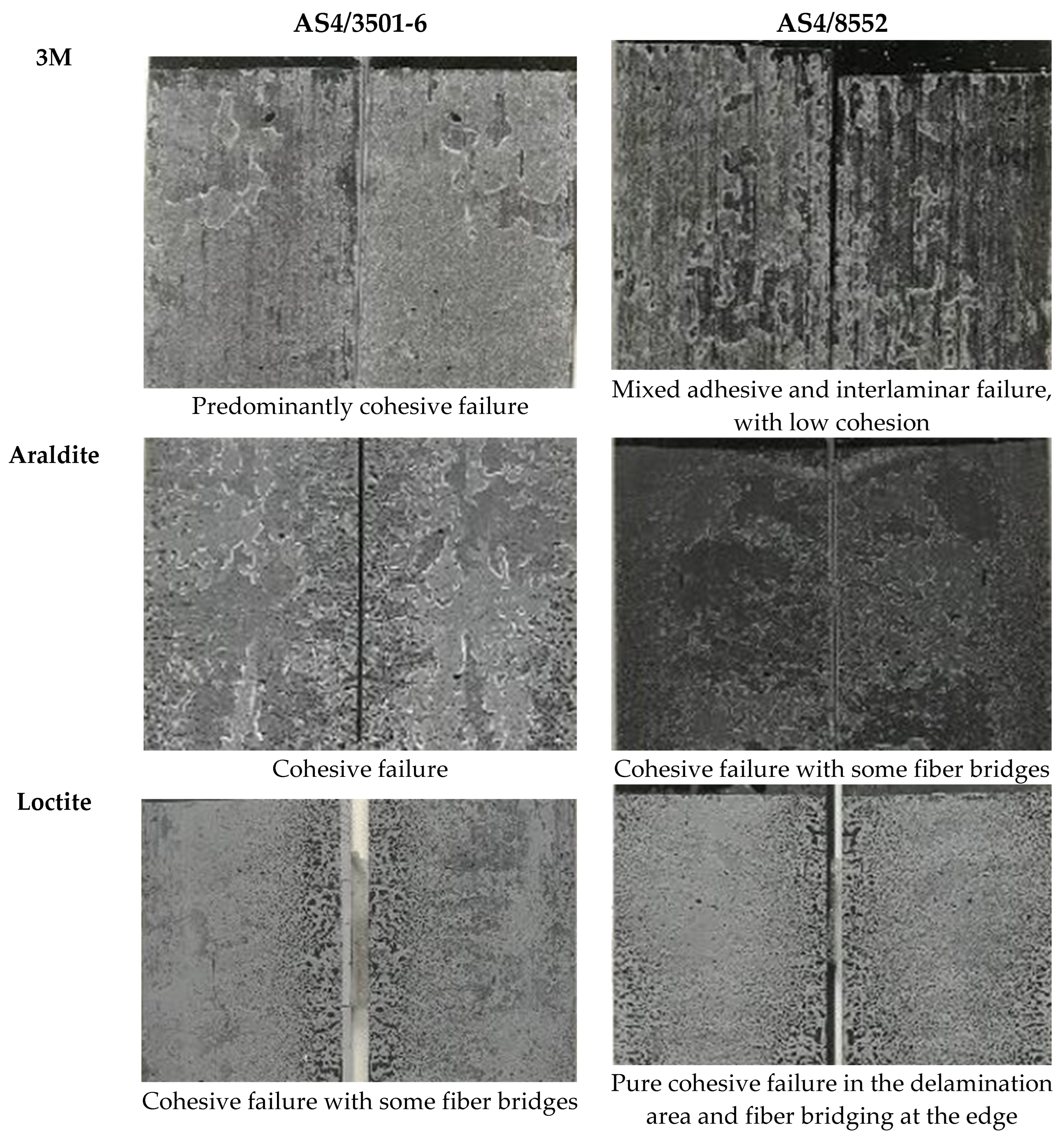
Figure 6 shows representative images of the fracture surfaces near the delamination initiation zone for the three adhesive systems and both composite materials. The different failure modes observed in selected specimens are indicated, depending on the adhesive formulation.
The analysis of the fracture surfaces revealed that cohesive failure was the dominant failure mode in most of the specimens analysed. The only exception corresponded to the acrylic-based 3M adhesive bonded to the AS4/8552 substrate, for which adhesive failure was predominant. However, this failure mode did not result in a reduction in the load-bearing capacity at the onset of delamination.
For the epoxy-based adhesives, cohesive failure was consistently observed in the delamination initiation zone, regardless of the substrate type. As crack propagation progressed, substrate or interlaminar failure became dominant, together with the appearance of small regions of adhesive failure distributed across the remaining fracture surface. Although limited fiber bridging was observed in some specimens, particularly during crack propagation, this mechanism played a secondary role in the overall fracture response. The primary contribution to the increased Mode I fracture energy arises from the presence of the adhesive layer and its associated deformation mechanisms.
Overall, for both composite materials investigated, the fracture surface morphologies observed during the delamination process did not exhibit substantial differences. Nevertheless, a reduction in the extent of the cohesive failure zone was detected, along with the appearance of isolated adhesive failure regions located away from the delamination initiation area.
For specimens bonded with the acrylic-based adhesive, the influence of the substrate was more pronounced. In the case of the AS4/8552 composite, a mixed adhesive–cohesive failure mode was observed over most of the fracture surface. This behavior was clearly identifiable and culminated in cohesive failure during the manual separation of the specimens at the end of the test. The mixed failure pattern can be attributed to the lack of symmetry between the opposing fracture surfaces. Adhesive failure was predominantly located in darker regions, whereas cohesive failure was associated with lighter areas. Additionally, a noticeable color change at the edges of the adhesive layer was observed, which is characteristic of plastic deformation prior to fracture in more ductile adhesive systems.
In contrast, for joints bonded with the acrylic-based adhesive on the AS4/3501-6 composite substrate, which exhibits a more brittle response, a dominant cohesive failure mode was consistently observed throughout the delamination process. This behavior is favored by the lower deformation capacity of the substrate, which limits plastic dissipation mechanisms and promotes cohesive fracture.
From an engineering perspective, this finding supports the feasibility of adhesive-based repair as an effective alternative to component replacement or extensive reprocessing. Similar approaches aimed at restoring the mechanical performance of CFRP systems after prior damage or processing have been reported in the literature, highlighting the potential of alternative strategies to extend material service life [36].

4. Conclusions

This study has demonstrated that adhesive-based repair strategies can partially restore the Mode I fracture performance of previously delaminated composite laminates. The results confirm that the effectiveness of the repair strongly depends on the mechanical behavior of the adhesive and its interaction with the fractured composite substrate.
Among the evaluated systems, the acrylic adhesive exhibited the highest fracture energy under Mode I loading, mainly due to its enhanced ductility and associated plastic deformation mechanisms within the adhesive layer. The contribution of fiber bridging, although observed in some cases, was limited and played a secondary role. Epoxy-based adhesives, in contrast, exhibited a more brittle response, resulting in lower apparent fracture toughness.
It is important to note that the measured increase in fracture energy is influenced by fiber bridging effects, particularly in the epoxy 3501-6 system. While this mechanism contributes to higher measured GIc values, it may lead to an overestimation of the intrinsic interfacial toughness. Nevertheless, these effects are representative of real repaired structures, where fiber bridging is expected to play a role in damage tolerance.
From an engineering perspective, the findings highlight that adhesive selection for composite repair should not be based solely on static strength or stiffness criteria, but also on the ability of the adhesive to dissipate energy under crack opening conditions. In this context, ductile adhesives may offer advantages for Mode I-dominated failure scenarios. The results of this study indicate that ductile acrylic-based adhesives may be preferable in repair scenarios dominated by Mode I loading, where energy dissipation and damage tolerance are important design requirements. Their enhanced ductility promotes progressive crack initiation and more stable crack propagation, which can be advantageous in structures subjected to crack opening, impact, or variable loading conditions. In contrast, epoxy-based adhesives, characterized by higher stiffness and a more brittle response, may be more suitable for applications where high load capacity, dimensional stability, or stiffness-driven performance is required, provided that crack opening deformations remain limited.
Overall, this work provides experimental evidence supporting adhesive-based repair as a viable strategy to extend the service life of composite structures, offering an alternative to component replacement or recycling, particularly in high-value structural applications.

Author Contributions

Conceptualization, A.A.; methodology, M.L.; validation, J.V.; investigation, P.V. All authors have read and agreed to the published version of the manuscript.

Funding

The authors acknowledge financial support from the Vice-Rectorate for Research at the University of Oviedo through the Research Support and Promotion Plan, project PAPI-22-PF-16, and from the Spanish Ministry of Science and Innovation through the project PID2024-159846OB-I00.

Data Availability Statement

The original contributions presented in this study are included in the article. Further inquiries can be directed to the corresponding author.

Conflicts of Interest

The authors declare no conflicts of interest.

References

  1. Elango, I.; Arumugam, V.; Dhakal, H.N. Fabrication and comparison of interlaminar fracture toughness behaviour of glass epoxy composites with recycled milled Kevlar-carbon hybrid fillers. Heliyon 2024, 10, e38842. [Google Scholar] [CrossRef]
  2. de Cássia Mendonça Sales, R.; Rossi Dias Endo, B.L.; Donadon, M.V. Influence of Temperature on Interlaminar Fracture Toughness of a Carbon Fiber-Epoxy Composite Material. Adv. Mater. Res. 2016, 1135, 35–51. [Google Scholar] [CrossRef]
  3. Vigón, P.; Argüelles, A.; Mollón, V.; Lozano, M.; Bonhomme, J.; Viña, J. Study of the Influence of the Type of Aging on the Behavior of Delamination of Adhesive Joints in Carbon-Fiber-Reinforced Epoxy Composites. Materials 2022, 15, 3669. [Google Scholar] [CrossRef]
  4. Takeda, T. Mode I fracture toughness determination and environmental durability evaluation of adhesive bonds by wedge test. Int. J. Adhes. Adhes. 2023, 127, 103521. [Google Scholar] [CrossRef]
  5. Zhang, L.; Sun, Y.; Huang, S.; Xu, H.; Zhang, Z.; Jiang, M.; Li, B.; Zong, L.; Wang, S.; Zhang, J. Poly(acrylic acid)-grafted cellulose nanocrystal reinforced supramolecular adhesives: Ultrahigh strength, humidity resistance, and pH-controlled recyclability. Carbohydr. Polym. 2025, 363, 123705. [Google Scholar] [CrossRef]
  6. Santos, D.; Akhavan-Safar, A.; Carbas, R.J.C.; Marques, E.A.S.; Wenig, S.; da Silva, L.F.M. Load-control vs. displacement-control strategy in fatigue threshold analysis of adhesives: Effects of temperature. Eng. Fract. Mech. 2023, 284, 109255. [Google Scholar] [CrossRef]
  7. Calabrese, A.S.; Bocciarelli, M.; D’Antino, T.; Papa, T.; Colombi, P. Repair and strengthening of existing structures using FRP composites externally-bonded with toughened epoxy adhesives. Procedia Struct. Integr. 2024, 64, 1832–1839. [Google Scholar] [CrossRef]
  8. Yildirim, C.; Ulus, H.; Beylergil, B.; Al-Nadhari, A.; Topal, S.; Yildiz, M. Effect of atmospheric plasma treatment on Mode-I and Mode-II fracture toughness properties of adhesively bonded carbon fiber/PEKK composite joints. Eng. Fract. Mech. 2023, 289, 109463. [Google Scholar] [CrossRef]
  9. Hashimoto, K.; Yashiro, S.; Onodera, S.; Ryuzono, K. Asymmetric stacking patch for debonding suppression in single-sided patch repair of composite structures. Compos. Struct. 2025, 355, 118843. [Google Scholar] [CrossRef]
  10. Yao, Y.; Shi, P.; Chen, M.; Chen, G.; Gao, C.; Boisse, P.; Zhu, Y. Experimental and numerical study on Mode I and Mode II interfacial fracture toughness of co-cured steel-CFRP hybrid composites. Int. J. Adhes. Adhes. 2022, 112, 103030. [Google Scholar] [CrossRef]
  11. May, M. Measuring the rate-dependent mode I fracture toughness of composites—A review. Compos. Part. A Appl. Sci. Manuf. 2016, 81, 1–12. [Google Scholar] [CrossRef]
  12. NASA. NASA Standard Tests for Toughened Resin Composites; NASA: Washington, DC, USA, 1983.
  13. Chai, H. On the correlation between the mode I failure of adhesive joints and laminated composites. Eng. Fract. Mech. 1986, 24, 413–431. [Google Scholar] [CrossRef]
  14. Schmandt, C.; Marzi, S. Effect of crack opening velocity and adhesive layer thickness on the fracture behaviour of hyperelastic adhesive joints subjected to mode I loading. Int. J. Adhes. Adhes. 2018, 83, 9–14. [Google Scholar] [CrossRef]
  15. Figueiredo, J.C.P.; Campilho, R.D.S.G.; Marques, E.A.S.; Machado, J.J.M.; da Silva, L.F.M. Adhesive thickness influence on the shear fracture toughness measurements of adhesive joints. Int. J. Adhes. Adhes. 2018, 83, 15–23. [Google Scholar] [CrossRef]
  16. Cooper, V.; Ivankovic, A.; Karac, A.; McAuliffe, D.; Murphy, N. Effects of bond gap thickness on the fracture of nano-toughened epoxy adhesive joints. Polymer 2012, 53, 5540–5553. [Google Scholar] [CrossRef][Green Version]
  17. Olhan, S.; Antil, B.; Behera, B.K. Repair technologies for structural polymeric composites: An automotive perspective. Compos. Struct. 2025, 352, 118711. [Google Scholar] [CrossRef]
  18. Gao, X.; Qian, H.; Wang, J.; Hong, Y.; Chen, Y.; Zhao, L.; Hu, D. Self-reinforced thermoplastic polyurethane composite with excellent mechanical properties, heat resistance and sustainable recycling. Compos. Part B Eng. 2025, 297, 112342. [Google Scholar] [CrossRef]
  19. Modestou, M.; Semitekolos, D.; Liu, T.; Podara, C.; Orfanidis, S.; Lima, A.T.; Charitidis, C. Recycling of Glass Fibers from Wind Turbine Blade Wastes via Chemical-Assisted Solvolysis. Fibers 2025, 13, 163. [Google Scholar] [CrossRef]
  20. Sahu, B.; Sahoo, C.K.; Chennamsetti, R.; Arockiarajan, A. Effect of graphene nanoparticles (GNP) on adhesively bonded patch repaired composite under tensile static and fatigue loading. Int. J. Adhes. Adhes. 2025, 142, 104072. [Google Scholar] [CrossRef]
  21. Ma, Y.; Nutt, S. Chemical treatment for recycling of amine/epoxy composites at atmospheric pressure. Polym. Degrad. Stab. 2018, 153, 307–317. [Google Scholar] [CrossRef]
  22. Liu, Y.; Farnsworth, M.; Tiwari, A. A review of optimisation techniques used in the composite recycling area: State-of-the-art and steps towards a research agenda. J. Clean. Prod. 2017, 140, 1775–1781. [Google Scholar] [CrossRef]
  23. Zhang, Y.; Vassilopoulos, A.P.; Keller, T. Effects of low and high temperatures on tensile behavior of adhesively-bonded GFRP joints. Compos. Struct. 2010, 92, 1631–1639. [Google Scholar] [CrossRef]
  24. Lechte, C.; Darwiche, R.; Hausdörfer, T.; Biermann, J.; Schmidt, A.; Wiegand, A.; Kanzow, P. Repairability of an alkasite composite: Shear bond strength after different surface treatments. Int. J. Adhes. Adhes. 2025, 140, 104012. [Google Scholar] [CrossRef]
  25. Yasar, M.; Prasad, V.; Hu, Y.; Murphy, N.; Ivankovic, A. Mode I Fracture Toughness Behaviour of Recyclable Piezoelectric Composites. Procedia Struct. Integr. 2024, 52, 165–175. [Google Scholar] [CrossRef]
  26. Moura, L.S.; Galvis, A.F.; Ramirez, A.F.; Abuquerque, E.L.; Sollero, P. Fatigue analysis of crack propagation in structures with bonded composite repairs. Eng. Anal. Bound. Elem. 2025, 172, 106116. [Google Scholar] [CrossRef]
  27. de Morais, A.B. A modified direct method to determine the bondline mode I traction-separation law from the adhesively bonded metal double cantilever beam specimen. Eng. Fract. Mech. 2025, 315, 110861. [Google Scholar] [CrossRef]
  28. Kojouri, A.S.; Karami, J.; Kalteremidou, K.A.; Fan, J.; Sharma, A.; Vassilopoulos, A.P.; Michaud, V.; Van Paepegem, W.; Van Hemelrijck, D. An experimental and analytical study of mode I fracture and crack kinking in thick adhesive joints. Compos. Part B Eng. 2024, 284, 111695. [Google Scholar] [CrossRef]
  29. Škec, L.; Alfano, G. Characterisation of mode-I fracture resistance of adhesive layers with imperfections. Eng. Fract. Mech. 2024, 301, 110028. [Google Scholar] [CrossRef]
  30. Ribas, M.; Akhavan-Safar, A.; Adam-Cottard, P.; Carbas, R.J.C.; Marques, E.A.S.; Wenig, S.; da Silva, L.F.M. Exploring strain rate variation in the adhesive layer during constant speed mode I fracture tests: Loading speed and test temperature effects. Theor. Appl. Fract. Mech. 2024, 130, 104274. [Google Scholar] [CrossRef]
  31. Gören, S.; Pereira, F.A.M.; Quyền, N.; de Moura, M.F.S.F.; Dourado, N. Fracture characterisation of a bi-material adhesive joint under mode I loading: Effect of roughness at the bonding interface. Int. J. Solids Struct. 2025, 310, 113221. [Google Scholar] [CrossRef]
  32. Taib, A.A.; Boukhili, R.; Achiou, S.; Gordon, S.; Boukehili, H. Bonded joints with composite adherends. Part I. Effect of specimen configuration, adhesive thickness, spew fillet and adherend stiffness on fracture. Int. J. Adhes. Adhes. 2006, 26, 226–236. [Google Scholar] [CrossRef]
  33. Banea, M.D.; Da Silva, L.F.M.; Campilho, R.D.S.G. Mode II fracture toughness of adhesively bonded joints as a function of temperature: Experimental and numerical study. J. Adhes. 2012, 88, 534–551. [Google Scholar] [CrossRef]
  34. Kouno, Y.; Imanaka, M.; Hino, R.; Omiya, M.; Yoshida, F. R-curve behavior of adhesively bonded composite joints with highly toughened epoxy adhesive under mixed mode conditions. Int. J. Adhes. Adhes. 2021, 105, 102762. [Google Scholar] [CrossRef]
  35. ASTM D 5528-01; Standard Test Method for Mode I Interlaminar Fracture Toughness of Unidirectional Fiber-Reinforced Polymer Matrix Composites 1. ASTM International: West Conshohocken, PA, USA, 2007.
  36. Tourkantoni, I.; Tserpes, K.; Marinis, D.; Farsari, E.; Amanatides, E. Mechanical Characterization of Carbon Fibers and Their Interfaces Recycled through Plasma-Assisted Solvolysis under Different Processing Conditions. Fibers 2025, 13, 158. [Google Scholar] [CrossRef]
Figure 1. (a) Specimen geometry and dimension; (b) Test with the type of grip used.
Fibers 14 00020 g001
Figure 2. (a) Extensometer (b) Specimen setup on the mechanical testing equipment.
Fibers 14 00020 g002
Figure 3. Load–displacement response of two carbon fiber types bonded with different adhesives. (a) AS4 8552; (b) AS4 3501-6.
Fibers 14 00020 g003
Figure 4. Mode I fracture toughness of AS4/8552 material.
Fibers 14 00020 g004
Figure 5. Mode I fracture toughness of AS4/3501-6 material.
Fibers 14 00020 g005
Figure 6. Fracture Surface.
Fibers 14 00020 g006
Table 1. Comparison of epoxy and acrylic adhesives.
PropertiesEpoxy (2-Components)Acrylic
Impact resistancePoorGood
Service temperature (°C)−55 to 120−70 to 120
Curing temperature/mixing requiredYesNo
OdorLowLow
ToxicityModerateModerate
FlammabilityLowLow
Table 2. Mechanical properties of AS4/8552 and AS4/3501-6 composites.
MaterialElastic ModulusTensile StrengthShear ModulusShear Strength
E11 GPaE22 [GPa]σ11 [MPa]σ22 [MPa]G12 [GPa]τmax [MPa]
855214410.6170330.85.3667.7
3501-61318.91954245.0979.3
11 Fiber direction; 22 Transverse to fiber direction.
Table 3. Basic properties of the adhesives used.
BaseViscosity [mPa·s]Tensile Modulus [GPa]Tensile Strength [MPa]Shear Strength [MPa]
Loctite® EA 9461TMEpoxy150,000 a 250,0002.7630.313.8
Araldite® 2015EpoxyThixotropic230.015.0
3MTM DP8810NSAcrylic45,0000.8611.376.9
Disclaimer/Publisher’s Note: The statements, opinions and data contained in all publications are solely those of the individual author(s) and contributor(s) and not of MDPI and/or the editor(s). MDPI and/or the editor(s) disclaim responsibility for any injury to people or property resulting from any ideas, methods, instructions or products referred to in the content.