1. Introduction
γ-TiAl alloys, owing to their low density, high specific yield strength, high specific stiffness, excellent oxidation resistance, and creep resistance [
1,
2], meet the requirements of modern aero-engine hot-section components for both lightweight design and high-temperature performance, and are regarded as one of the most promising alternatives to titanium alloys and nickel-based superalloys in aerospace applications [
3,
4]. However, due to their intrinsic brittleness, high hardness, and low thermal conductivity [
5], γ-TiAl alloys often suffer from high cutting temperatures, severe tool wear, and poor surface integrity during machining. These material-induced machining difficulties seriously restrict the wider application of γ-TiAl alloys in safety-critical aerospace components.
In recent years, to alleviate severe tool wear and poor surface integrity when machining difficult-to-cut materials. It has been widely recognized that machining performance is strongly influenced by cutting parameters. Özbek et al. [
6] reported that cutting conditions, especially feed rate, play a dominant role in affecting tool wear and surface roughness during turning of AISI 304 stainless steel. In addition to process optimization, improving tool properties has also been proven to be an effective approach. Kursuncu et al. [
7] demonstrated that multilayer nanocomposite coatings combined with cryogenic heat treatment can significantly improve the cutting performance of carbide tools, particularly in terms of reducing tool wear, during milling of Inconel 718.
Furthermore, cooling and lubrication strategies have been extensively investigated as other important approaches to improving machining performance. Conventional flood cooling, liquid nitrogen (LN
2) cooling, and minimum quantity lubrication (MQL) have been widely employed to improve machining performance. Studies have shown that these approaches can, to some extent, improve the thermo-mechanical load in the cutting zone, tool life, and surface integrity. Nevertheless, each method has inherent limitations. Conventional flood cooling is widely used and relatively low in cost; however, under high-speed machining of difficult-to-cut materials, the coolant has difficulty penetrating into the cutting zone [
8]. LN
2 cooling is highly effective in reducing cutting temperature, but it suffers from high storage and transportation costs and may cause material embrittlement at low temperatures [
9]. MQL reduces coolant consumption and enhances machining performance, but its cooling capability for difficult-to-cut materials remains insufficient [
10].
High-pressure cooling (HPC) enhances coolant penetration into the cutting zone by increasing fluid pressure, thereby accelerating heat transfer between the tool and the workpiece and significantly improving cooling and lubrication performance [
11]. In recent years, tool wear and surface integrity of difficult-to-machine materials under high-pressure jet assistance have attracted increasing attention. Bermingham et al. [
12] compared cryogenic cooling with HPC during Ti-6Al-4V turning and found that HPC outperformed in terms of tool life, chip-breaking capability, cutting-zone penetration, and nozzle positioning tolerance. Li et al. [
13] demonstrated that HPC effectively reduced tool wear when machining GH4169 with PCBN tools. Regarding surface quality, most studies indicate that HPC provides certain improvements. Dahlman et al. [
14] reported that, in near-net-shape turning of decarburized steel, ultra-high-pressure cooling reduced surface roughness by approximately 80% and significantly decreased surface defects compared with dry cutting. Velan et al. [
15] observed that HPC reduced cutting forces by 12–23% and improved surface roughness by 14–33% when turning AISI 1045. However, some studies suggest that the effect of HPC on surface roughness is inconsistent. Ezugwu et al. [
16] found negligible differences in surface roughness between conventional flood cooling and HPC during Ti-6Al-4V turning, although HPC reduced feed marks, micro-pits, and re-deposited material. Similar conclusions were drawn by Habak et al. [
17] during high-pressure water-jet-assisted machining of austenitic stainless steel, where HPC had limited impact on roughness but significantly decreased tool wear. Kaynak et al. [
18] reported that, when machining Ti-5553 at various cutting speeds, both HPC and MQL could achieve acceptable surface roughness under most conditions compared with flood cooling. In terms of subsurface integrity, HPC has been shown to mitigate machining-induced damage. Ezugwu et al. [
19] reported that, during Inconel 718 machining with ceramic tools, HPC reduced the depth of the plastic deformation layer. Liang et al. [
20] investigated Ti-6Al-4V under different pressures and nozzle positions and found that HPC decreased plastic deformation and work hardening, with higher pressures further diminishing these effects. Xu et al. [
21] observed similar trends in nickel-based superalloy grinding, where HPC markedly reduced the plastic deformation layer and nearly eliminated white and recrystallized layers. These findings indicate that HPC generally reduces tool wear and improves surface integrity; however, most studies have focused on titanium alloys, superalloys, and steels.
For γ-TiAl alloys, research on HPC remains limited. Sharman et al. [
22] investigated precision turning of γ-TiAl under 20 bar and 65 bar HPC and found that while cutting forces decreased, surface roughness increased. Klocke et al. [
23] compared conventional flood cooling and HPC in γ-TiAl turning and reported that HPC significantly reduced tool wear (29% reduction at 80 bar and 41% at 300 bar) and decreased material plastic deformation, whereas surface roughness remained unchanged at 80 bar but increased at 300 bar. Existing studies on HPC machining of γ-TiAl primarily focus on the influence of cooling pressure, with limited exploration of the combined effects of cutting speed and cooling strategy on tool wear mechanisms and subsurface integrity evolution.
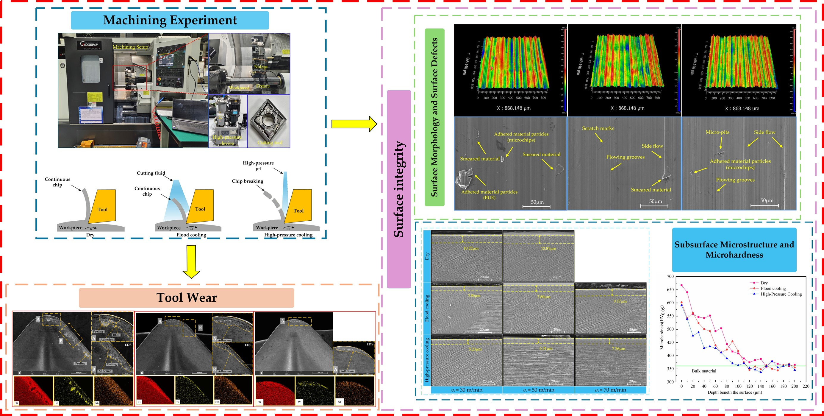
Overall, existing studies indicate that HPC exhibits clear advantages in machining difficult-to-cut materials. However, systematic investigations into tool wear and surface integrity of γ-TiAl alloys under HPC remain limited, and most available studies focus primarily on cooling pressure. Therefore, this work investigates the effects of different cutting speeds (30, 50, and 70 m/min) and cooling conditions (dry cutting, flood cooling, and high-pressure cooling) on tool wear and surface integrity during machining of γ-TiAl alloys. Tool wear, machined surface morphology, surface defects, microstructure, and microhardness are comprehensively evaluated to assess the applicability of HPC for γ-TiAl alloy machining.
3. Results and Discussion
3.1. Tool Wear
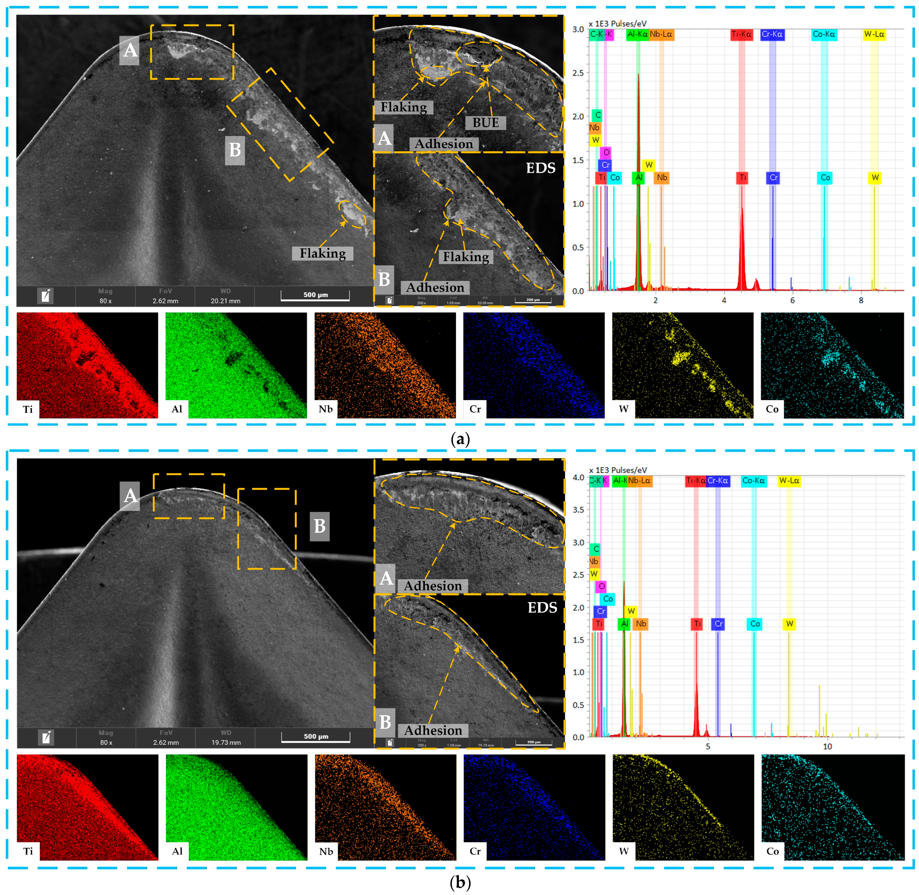
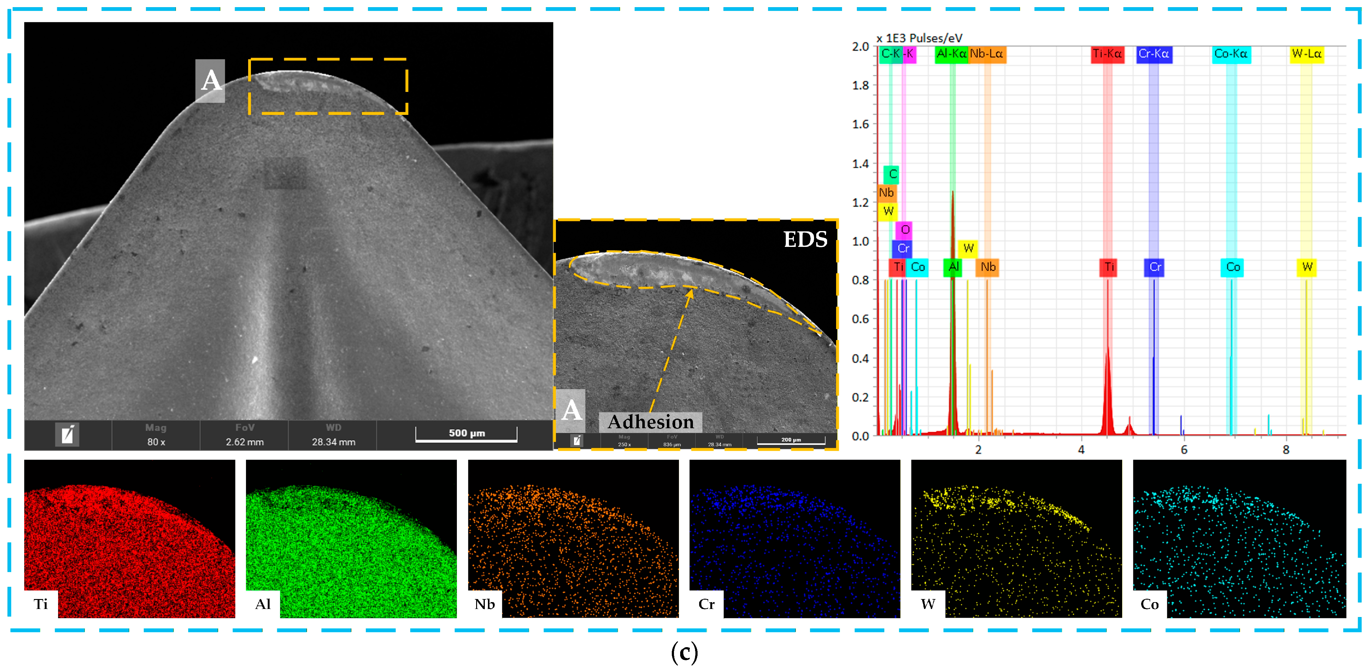
Figure 2 shows the SEM images and energy dispersive spectroscopy (EDS) results of the tool rake face under different cooling conditions.
Figure 2a shows that, under dry cutting, a large amount of adhered workpiece material is accumulated on the rake face and forms built-up edge (BUE), while severe coating flaking is also observed. The EDS spectra reveal the presence of Ti, Al, Nb, and Cr within the adhered layer. Since Nb and Cr are constituent elements of the γ-TiAl workpiece, their detection on the rake face confirms material transfer from the workpiece to the tool. In addition, higher Ti content and lower Al content were detected near the cutting edge, indicating that the Ti content exceeds that of the coating, while the Al content is lower than that of the coating, further confirming severe adhesion. The presence of W and Co in the adhered region indicates that coating delamination has peeled off. These observations indicate that adhesive wear dominates under dry cutting. During dry cutting, the absence of effective cooling and lubrication, combined with the poor thermal conductivity of the γ-TiAl alloy, promotes atomic-scale contact and strong adhesion between the tool and the workpiece under high temperature and pressure [
24]. As cutting progresses, the bonding strength between the adhered material and the tool gradually decreases under cyclic mechanical loading, eventually leading to detachment of the adhered layer. During this detachment process, portions of the tool material are often removed simultaneously, resulting in coating flaking and the formation of fresh adhered material. This repeated adhesion–detachment cycle ultimately accelerates tool wear.
Figure 2b shows the tool wear morphology under flood cooling. The EDS analysis indicates that Nb, Cr, and Ti remain detectable in the adhered region, demonstrating that adhesive wear remains the dominant mechanism, but the adhesion area is significantly smaller than that under dry cutting. This is mainly attributed to the cooling and lubricating effects of the cutting fluid, which reduce the thermo-mechanical load and weaken the adhesion tendency between the workpiece and the tool.
Figure 2c shows the SEM and EDS results of the rake face under high-pressure cooling. Compared with conventional flood cooling, high-pressure jets are capable of penetrating the tool–chip interface more efficiently, maintaining fluid access even under elevated temperature conditions [
25]. Enhanced heat removal and lubrication reduce interface temperature and shear stress, thereby weakening adhesion intensity and limiting coating damage. Overall, under the three cooling conditions, adhesive wear is the dominant wear mechanism on the rake face. The most severe wear occurs under dry cutting, followed by flood cooling, while the smallest rake face wear is obtained under high-pressure cooling.
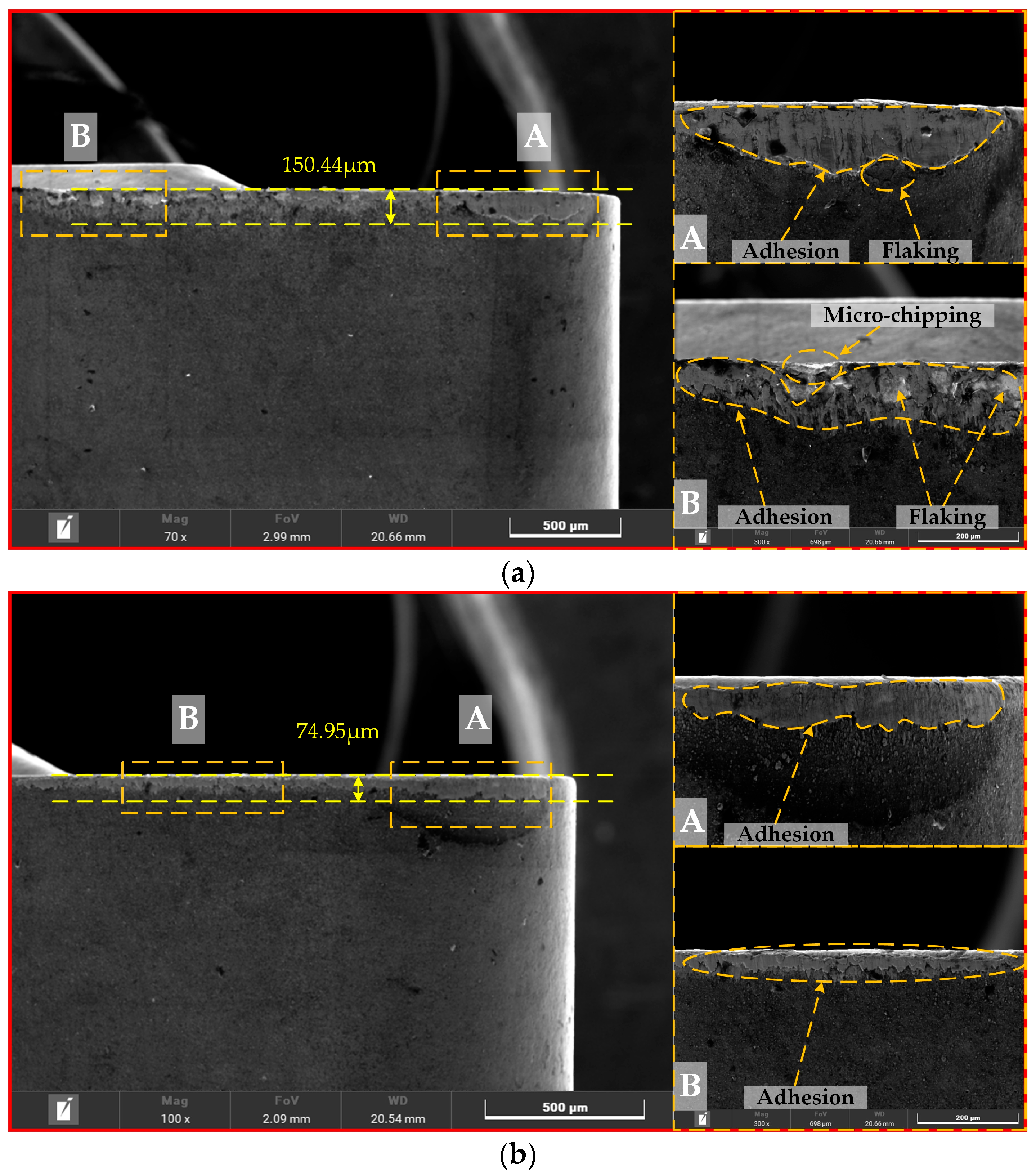
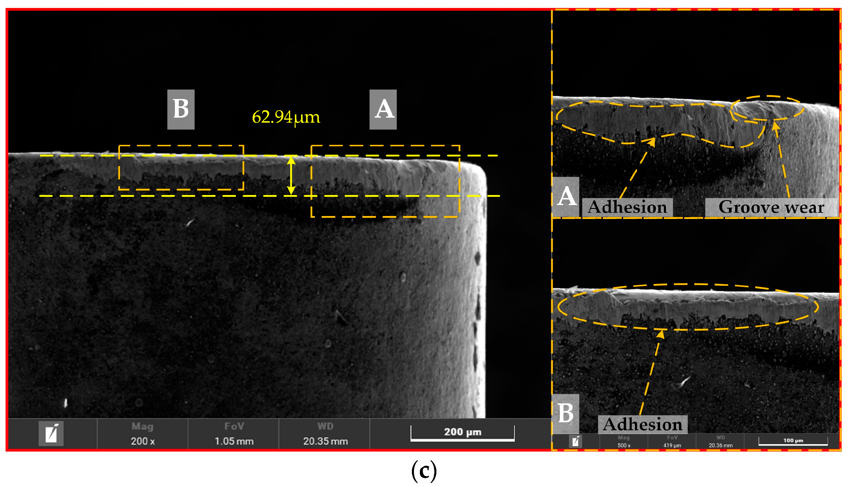
Figure 3 shows the SEM images of nose wear under different cooling conditions. Similar to the rake-face observations, adhesive wear is the dominant mechanism on the nose for all cooling strategies. In dry cutting, shown in
Figure 3a, severe adhesion of workpiece material and coating flaking are observed on the tool nose region, accompanied by micro-chipping near the cutting edge, resulting in a nose wear value of 150.44 μm. This is attributed to the repeated adhesion and detachment of workpiece material, which removes tool material and promotes edge failure.
Figure 3b shows that under flood cooling, adhesive wear remains predominant, but the adhesion area is noticeably reduced compared with dry cutting, leading to a reduced nose wear value of 74.95 μm.
Figure 3c shows that under high-pressure cooling, the tool nose region exhibits the smallest adhesion region and comparatively intact coating, with a further reduced nose wear value of 62.94 μm. However, slight groove wear appears near the cutting edge, which is consistent with previous findings [
11]. This feature may be associated with the high velocity coolant jet impacting the cutting zone, which can induce stress concentration and micro-scale surface damage. Overall, a clear decreasing trend in nose wear is observed from dry cutting to high-pressure cooling, indicating that enhanced cooling and lubrication effectively suppress tool wear. Nose wear follows a similar trend to rake-face wear, with adhesive wear as the dominant wear mechanism.
3.2. Surface Morphology and Roughness
Surface morphology is an essential aspect of surface integrity and plays a critical role in determining the fatigue strength of machined components [
26].
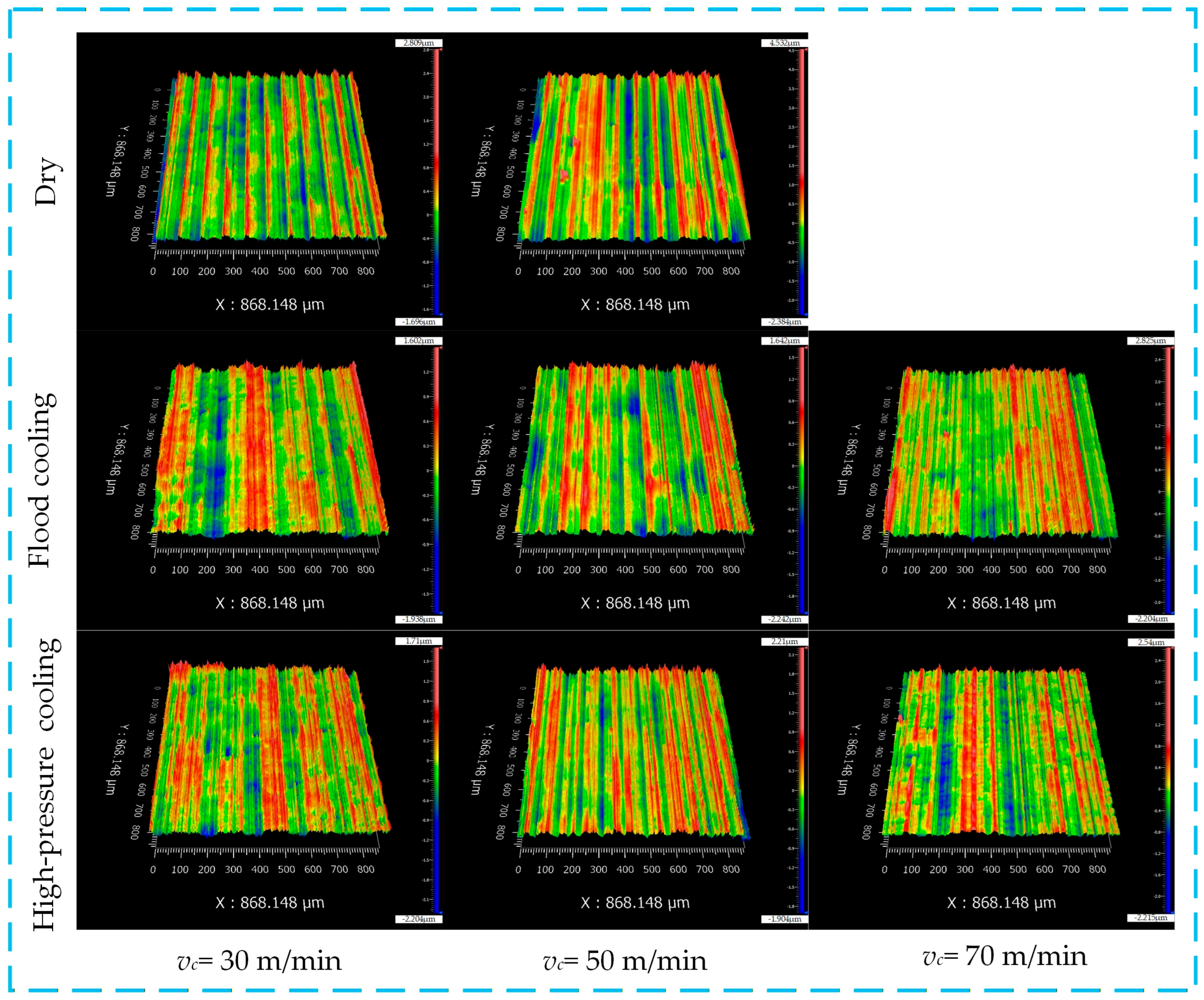
Figure 4 presents the three-dimensional surface topographies of γ-TiAl alloy under different cutting conditions. Under dry cutting, the machined surfaces exhibit distinct and evenly spaced raised ridges with pronounced peaks and valleys, indicating a relatively rough surface. In comparison, flood cooling reduces the prominence of the ridges and decreases the peak-to-valley variations, leading to a more uniform surface texture. High-pressure cooling produces the smoothest ridges and the smallest peak-to-valley fluctuations, suggesting that material separation and flow are more stable under this condition, which favors superior surface quality.
To quantitatively compare the surface characteristics under different cutting conditions, the amplitude parameters of the machined surfaces, including the arithmetic mean height (Sa), root mean square height (Sq), skewness (Ssk), and kurtosis (Sku), were evaluated. Here, Sa represents the arithmetic mean of the surface heights within the measured area; Sq reflects the standard deviation of the surface heights; Ssk describes the symmetry of the height distribution relative to the mean plane; and Sku indicates the sharpness of the height distribution. The corresponding calculation formulas are given in Equations (1)–(4).
In the above equations, represents the measured area and denotes the surface height at coordinates within this area.
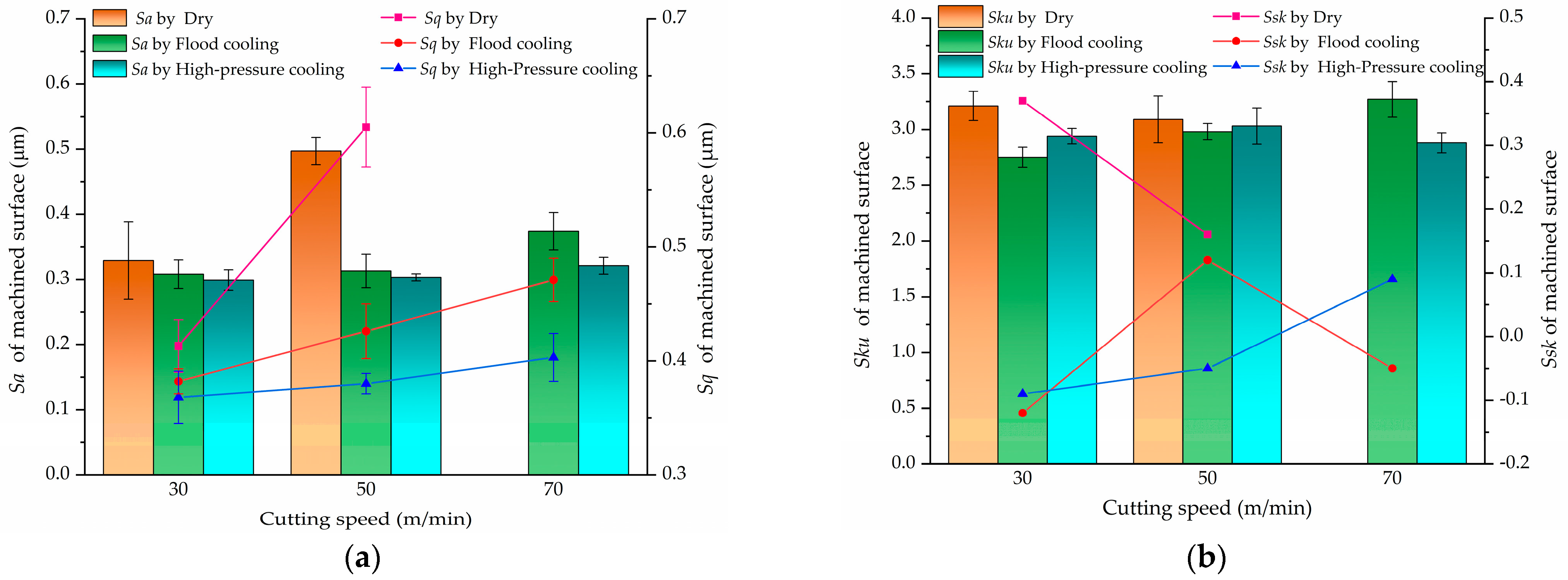
Figure 5a presents the variations in surface roughness (Sa) of γ-TiAl alloy under different cooling conditions. Under dry cutting, the highest Sa values are obtained: 0.329 µm and 0.497 µm for cutting speeds
vc = 30 m/min and 50 m/min, respectively. Flood cooling significantly reduces Sa, which is 0.308 µm, 0.313 µm, and 0.374 µm at
vc= 30, 50, and 70 m/min, respectively. High-pressure cooling further improves the machined surface quality, with corresponding Sa values of 0.299 µm, 0.303 µm, and 0.321 µm for the same cutting speeds.
The higher roughness under dry cutting is associated with intensified tool wear and elevated interface temperature, which promote unstable material flow and larger residual height on the machined surface [
27]. As previously discussed in the tool wear analysis, severe adhesion and coating delamination under dry conditions increase cutting edge degradation, leading to greater surface irregularities. In contrast, under flood and high-pressure cooling, the introduction of cutting fluid mitigates the thermo-mechanical coupling between the tool and workpiece, reducing tool wear and the residual height of the surface, and thus improving surface roughness. High-pressure cooling, in particular, delivers the cutting fluid to the cutting zone in a stable and precise manner via a high-velocity jet. Its cooling and lubricating effects are especially pronounced at higher cutting speeds, effectively suppressing tool wear and further reducing surface roughness. Overall, surface roughness increases with cutting speed; however, under flood and high-pressure cooling, the increase is relatively moderate, indicating that cutting speed has a limited effect on surface roughness in these conditions. By contrast, under dry cutting, the variation in surface roughness is more pronounced, primarily due to severe tool wear leading to increased residual heights.
The trend of Sq is consistent with that of Sa: both parameters are highest under dry cutting and lowest under high-pressure cooling, increasing gradually with cutting speed. Kurtosis (Sku) characterizes the sharpness of the surface height distribution. Sku = 3 corresponds to a completely random surface; Sku < 3 indicates a relatively flat distribution, while Sku > 3 reflects a surface with more pronounced peaks. Skewness (Ssk) describes the symmetry of the height distribution relative to the reference plane; Ssk = 0 indicates a symmetric distribution, negative Ssk indicates a predominance of valleys, and positive Ssk indicates a predominance of peaks.
As shown in
Figure 5b, under dry cutting, Sku > 3 and Ssk > 0, indicating that the machined surface is dominated by peak features. Under flood and high-pressure cooling, Sku and Ssk do not show a clear trend with cutting speed. However, under high-pressure cooling, Sku fluctuates around 3 and Ssk remains close to 0, suggesting a more symmetric peak–valley distribution. In contrast, under flood cooling, Sku and Ssk vary more randomly with cutting speed, indicating less uniform surface morphology. This is mainly attributed to the flushing effect of the high-pressure jet on the machined surface, which suppresses the formation of extreme asperity peaks during the turning process.
3.3. Surface Defects
During machining, various surface defects can be observed, especially at the microscopic scale. In this study, SEM was used to examine the machined surfaces, and the main defects identified include feed marks, adhered material particles, smeared material, plowing grooves, side flow, surface tearing, micro-pits, and scratch marks.
As shown in
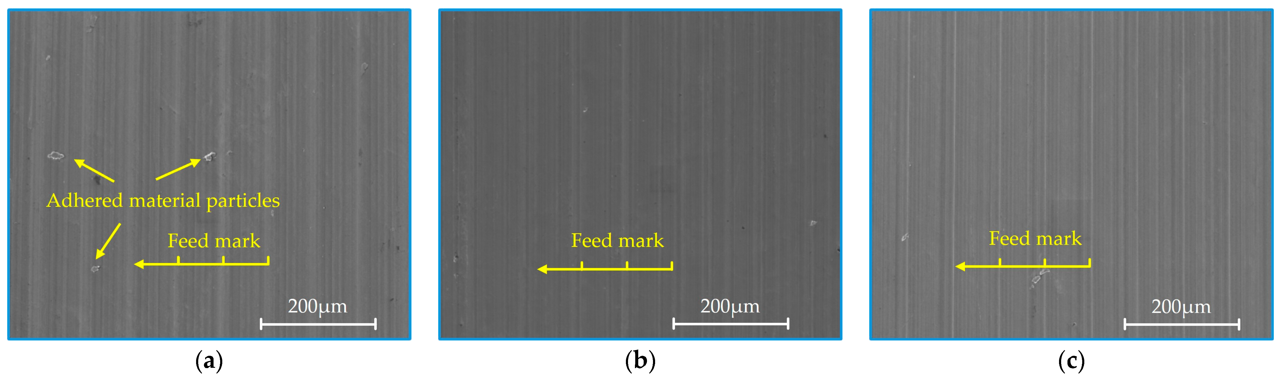
Figure 6, pronounced tool feed marks are observed under all cooling conditions at a cutting speed of 50 m/min. Feed marks are inherent defects generated by the feed motion during machining [
28]. Dry cutting exhibits the most severe feed marks, likely due to the absence of cooling and lubrication. In this case, the workpiece surface is subjected to intense thermo-mechanical coupling, and thermal softening promotes plastic deformation, amplifying the “plowing” effect of the tool and resulting in more distinct feed marks.
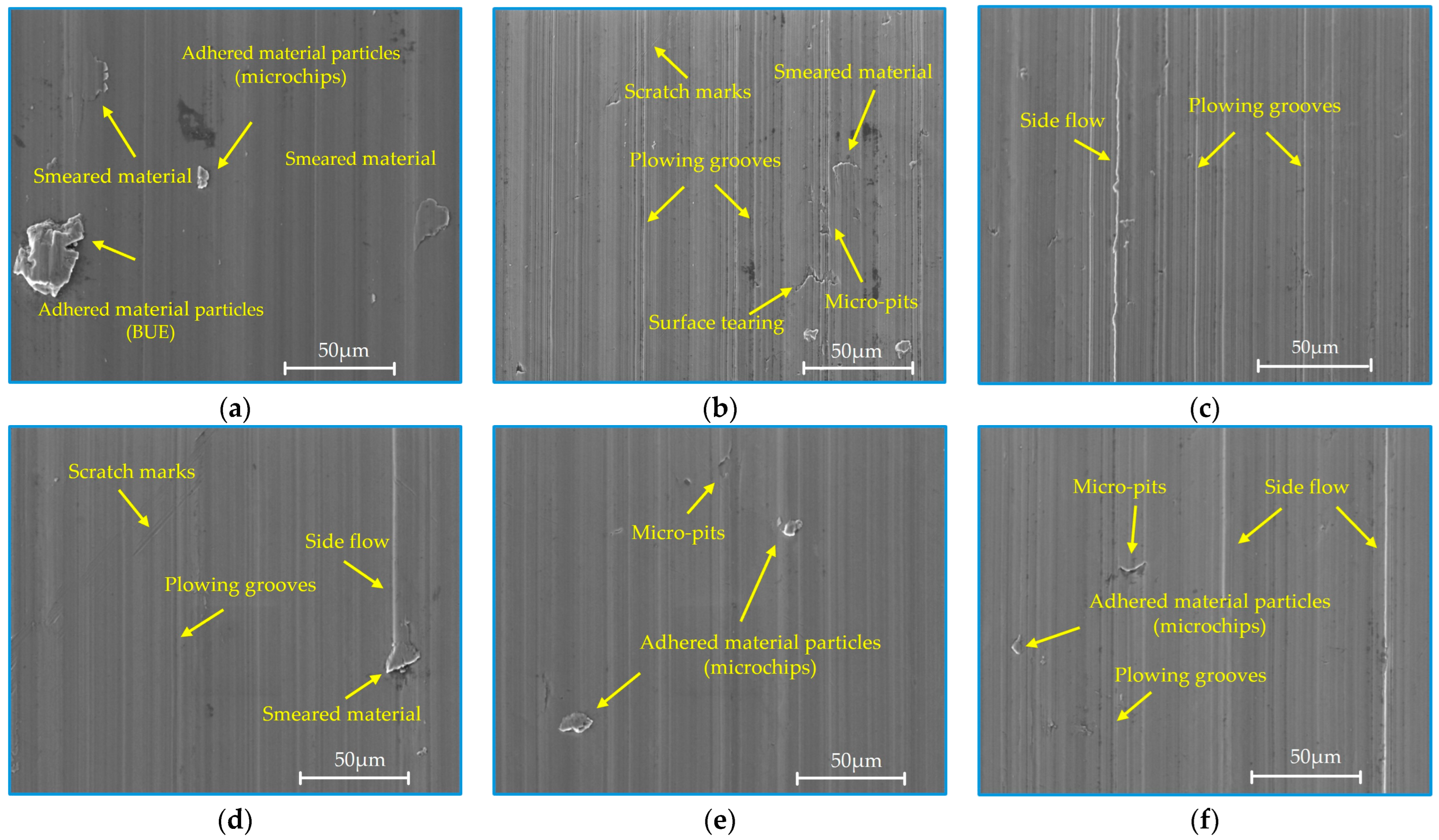
Figure 7 presents the surface defects observed under dry cutting, flood cooling, and high-pressure cooling conditions at a cutting speed of 50 m/min. As shown in
Figure 7a, under dry cutting, adhered material particles are present on the machined surface, mainly composed of large BUE and microchips. This phenomenon is attributed to the severe thermo-mechanical loading imposed on the machined surface under dry cutting conditions, where elevated interface temperatures promote the formation of BUE and facilitate the adhesion of fragmented material onto the surface.
When these adhered particles are subsequently compressed between the flank face of the tool and the machined surface, severe plastic deformation occurs, resulting in smeared material on the surface. Plowing grooves, a common type of surface defect, are observed under all three cooling conditions, as shown in
Figure 7b,e,f. The formation of these grooves is primarily associated with the plowing action of hard precipitates in the workpiece material or fragmented particles from the cutting edge [
29]. Studies have shown that improving cooling conditions can reduce both the number and severity of plowing grooves, as the lubricating effect of the cutting fluid in flood and high-pressure cooling reduces friction at the tool–workpiece interface [
20].
Moreover, when adhered material particles detach from the machined surface, they often remove portions of the workpiece material, leading to surface tearing, as illustrated in
Figure 7b [
30]. The formation of micro-pits is generally related to material delamination.
Figure 7c,d,f show that side flow typically occurs in the feed mark regions; when the actual uncut chip thickness is below the minimum cutting thickness, the material is pushed to the sides due to plastic deformation [
31]. Under dry cutting, the extent of side flow is more pronounced, which is attributed to the higher thermo-mechanical loads induced by increased tool wear [
29]. Additionally, adhered hard particles sliding between the tool and the workpiece can cause scratch marks on the machined surface.
Figure 7d,e illustrate typical surface defects under flood cooling. Compared with dry cutting, flood cooling reduces the adhesion of BUE and surface tearing. High-pressure cooling further decreases the types and severity of surface defects, as shown in
Figure 7f. In particular, the reduction in adhered material particles is more pronounced under high-pressure cooling, which can be attributed to the ability of the high-velocity jet to effectively penetrate the cutting zone and establish a stable lubricating film at the tool–workpiece interface, thereby suppressing the deposition of BUE and chip fragments.
As shown in
Table 4, dry cutting exhibits the highest severity in adhesive material particles and micro-pits, while flood cooling shows a moderate reduction in most defect types. High-pressure cooling further suppresses the occurrence and severity of surface defects, particularly in terms of adhesive material particles and smeared material. These results are consistent with the SEM observations in
Figure 7 and further confirm the effectiveness of high-pressure cooling in improving surface integrity.
3.4. Subsurface Microstructure
During machining, severe thermo-mechanical loads induce compressive and shear deformation, causing the surface grains to distort, elongate, twist, and slip, resulting in plastic deformation of the surface layer [
32,
33].
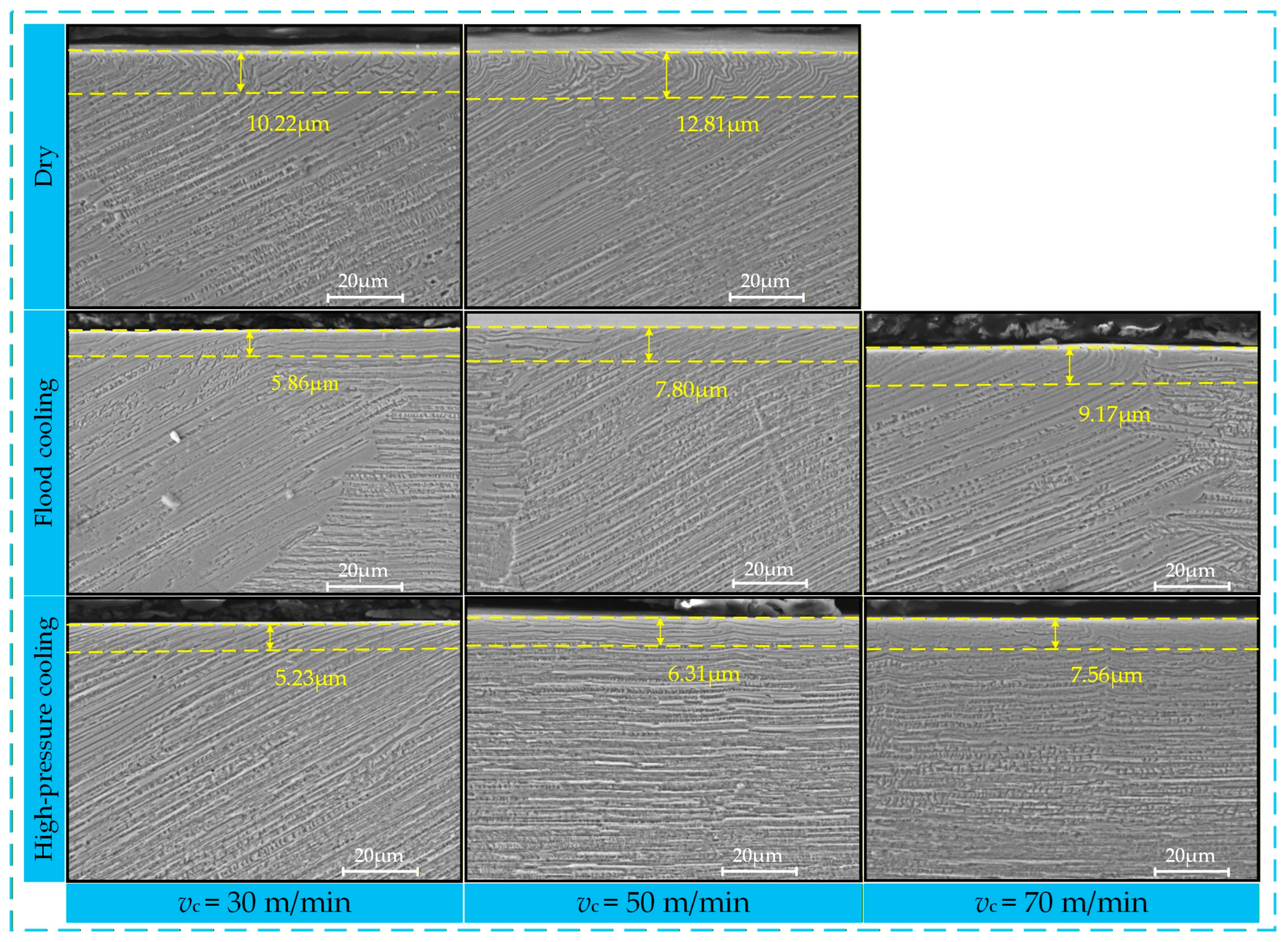
Figure 8 presents the microstructure of the machined surface cross-sections of γ-TiAl alloy under dry cutting, flood cooling, and high-pressure cooling at different cutting speeds. In all three cooling conditions, a distinct plastically deformed layer is observed. Due to the unique lamellar structure of γ-TiAl alloy [
34], plastic deformation predominantly manifests as bending, distortion, and deflection of the lamellae, which can be observed in SEM cross-sectional images together with flow and extrusion traces, indicating the occurrence of severe plastic deformation. The γ-TiAl alloy consists of a lamellar colony structure composed of alternating γ and α
2 phases, with multiple crystallographic orientations among different colonies, resulting in pronounced anisotropic deformation behavior [
35]. When the lamellae are in a soft orientation, shear deformation preferentially occurs along the lamellar interfaces, facilitating plastic deformation, whereas under hard orientation, shear deformation must occur across the lamellar interfaces and is therefore hindered by interfacial constraints [
36]. During machining, such orientation-dependent behavior leads to heterogeneous deformation among different regions, resulting in non-uniform plastic flow and multi-directional deformation features in the subsurface region. Among the cooling conditions, dry cutting produces the thickest plastically deformed layer, followed by flood cooling, with high-pressure cooling resulting in the thinnest layer.
Specifically, at cutting speeds of 30 m/min and 50 m/min, the thickness of the plastically deformed layer under dry cutting is 10.22 µm and 12.81 µm, respectively. Under the same cutting speeds, the plastically deformed layer thickness is reduced by approximately 44.46% and 39.11% for flood cooling, and 48.82% and 50.74% for high-pressure cooling. At 70 m/min, compared with flood cooling, high-pressure cooling further reduces the plastically deformed layer thickness by approximately 17.55%. These differences are mainly attributed to the influence of thermo-mechanical loads on the extent of plastic deformation during cutting.
Under dry cutting, the absence of effective cooling and lubrication causes the cutting zone temperature to rise rapidly. This leads to pronounced thermal softening and heat accumulation, allowing plastic deformation to penetrate deeper into the material. In contrast, high-pressure cooling significantly suppresses the thermal load, and the lubricating effect of the high-velocity jet reduces friction between the tool–workpiece and tool–chip interfaces, enhancing chip breaking. Furthermore, the jet improves fluid penetration, further enhancing cooling and lubrication in the cutting zone.
Additionally, as shown in
Figure 8, increasing cutting speed leads to a thicker plastically deformed layer under all cooling conditions. This is mainly due to higher cutting speeds generating greater cutting heat, which increases the strain rate in the cutting zone and amplifies friction between the tool and workpiece, resulting in more significant thermo-mechanical loads and plastic deformation.
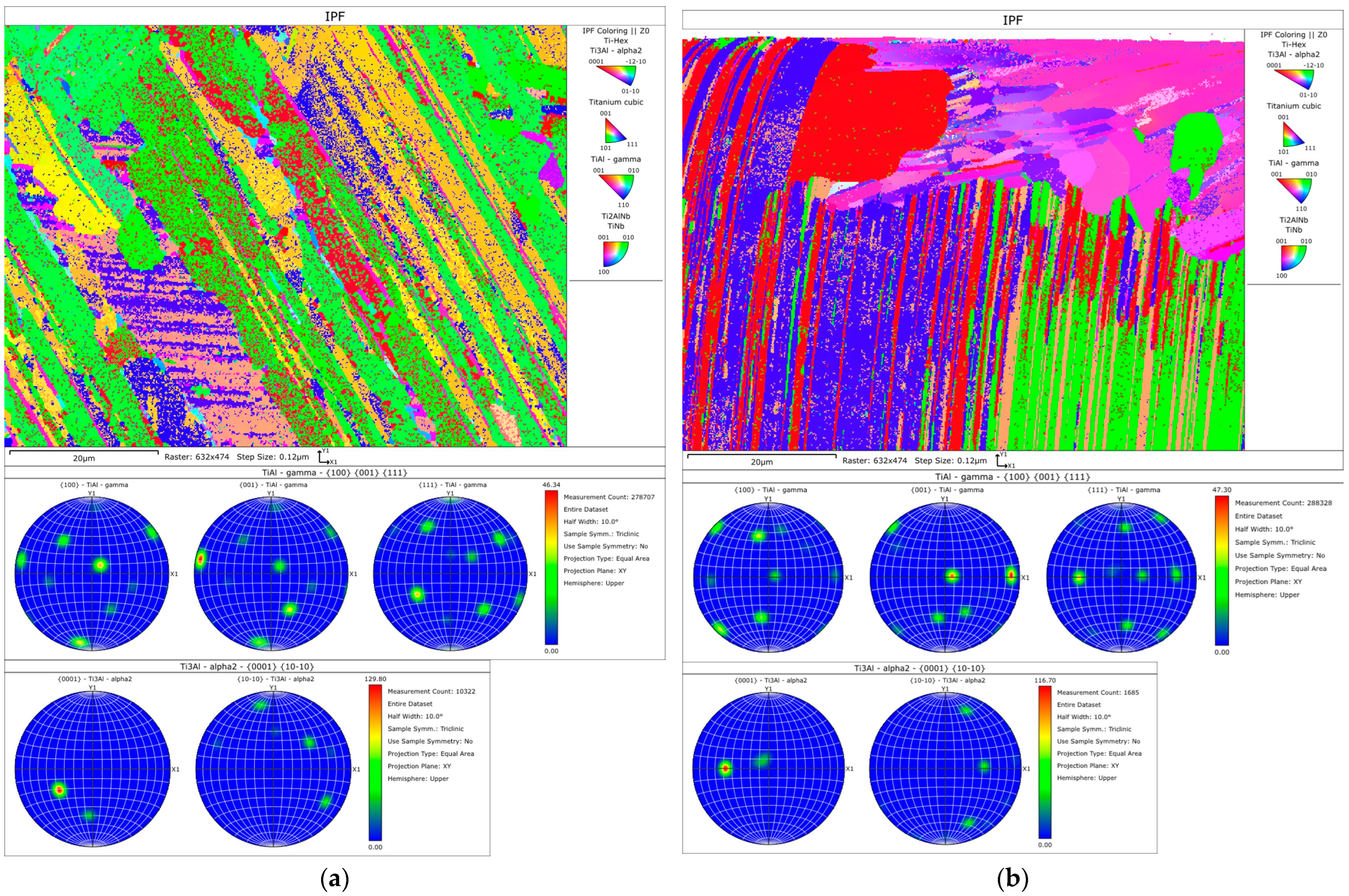
To further investigate the evolution of grain characteristics in the plastically deformed layer of the machined surface, compared with the γ-TiAl alloy bulk.
Figure 9 presents the EBSD inverse pole figure (IPF) maps and pole figures of the γ-TiAl alloy in the bulk region and subsurface region under dry cutting conditions. The bulk region exhibits a typical as-cast microstructure, mainly composed of lamellar γ/α
2 colonies and a small fraction of equiaxed γ grains, with well-defined grain boundaries and relatively random orientation distribution. As shown in the IPF map, the grain colors are uniformly distributed without obvious clustering, indicating a weak overall texture intensity. The pole figures further reveal that the γ phase is randomly distributed with no pronounced preferred orientation, whereas the α
2 phase exhibits a distinct texture concentration along the <0001> direction, suggesting orientation selectivity during solidification and cooling.
Under dry cutting conditions, significant microstructural evolution occurs in the machined surface layer, as shown in
Figure 9b. The grains exhibit pronounced bending and elongation. The IPF map shows a more concentrated color distribution, indicating that the grain orientations in local regions tend to align, which suggests the formation of preferred orientation during machining. The pole figures demonstrate an increased texture intensity of the γ phase, implying that crystallographic reorientation and plastic deformation have taken place. In contrast, the texture intensity of the α
2 phase shows negligible change compared to the bulk, and its original orientation characteristics are largely retained. This texture evolution is primarily attributed to the combined effects of elevated temperature and severe plastic deformation during dry cutting.
Figure 10 shows the grain size distributions of the bulk and machined surface layer. The results indicate that the average grain size in the bulk region is 4.23 μm, whereas it decreases to 3.89 μm in the machined surface layer, indicating grain refinement. This is mainly attributed to the thermo-mechanical coupling effect during machining, which induces localized stress concentration, leading to grain fragmentation and dynamic recrystallization, and consequently the formation of finer grains with more uniform orientations.
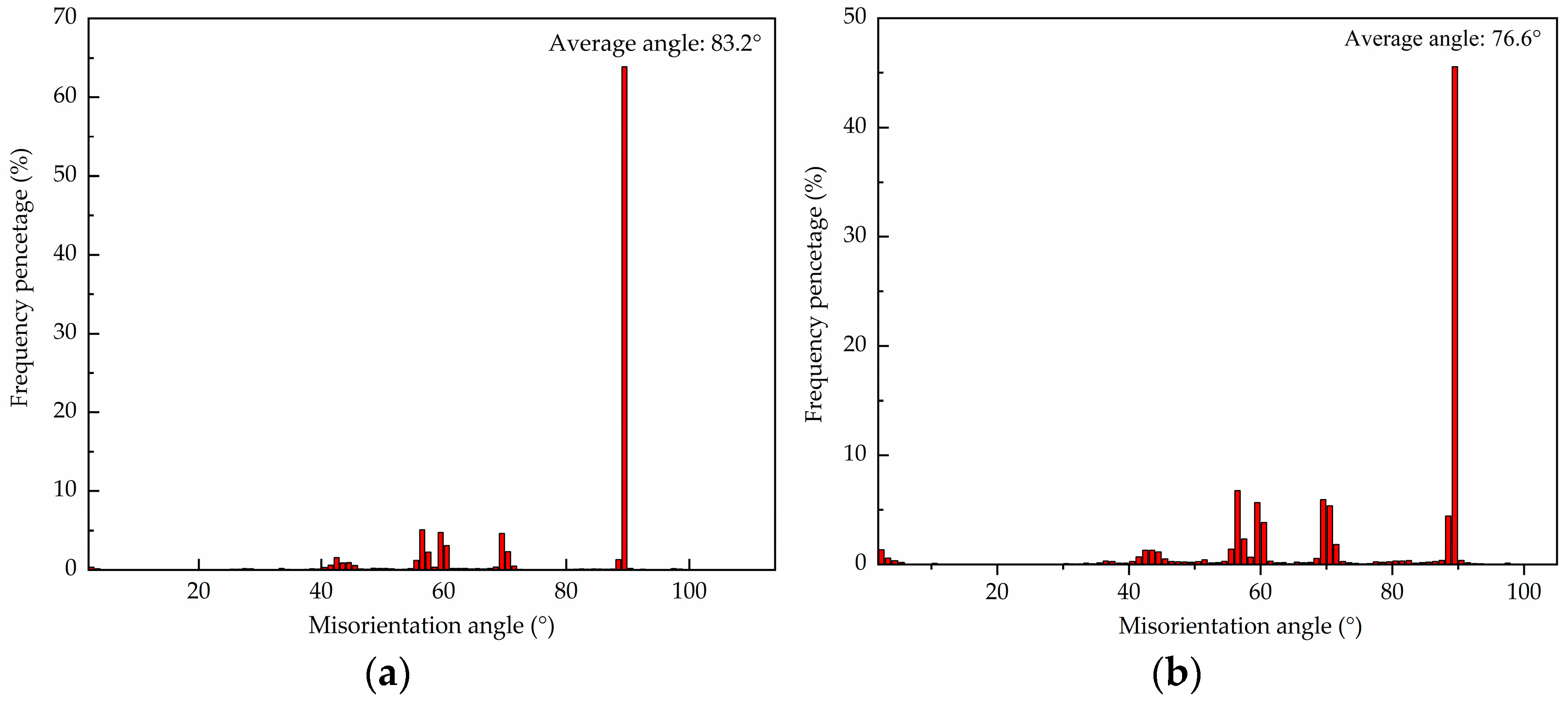
As shown in
Figure 11, the misorientation angle distributions in both the bulk and machined surface layer are dominated by high-angle grain boundaries (HAGBs). In the bulk region, far from the machined surface, the misorientation angles are mainly concentrated in the high-angle range (>80°), with an average misorientation angle of 83.2°, indicating a large orientation difference between grains, which is consistent with the random orientation distribution of the as-cast microstructure. In contrast, the average misorientation angle in the machined surface layer decreases to 76.6°, accompanied by an increase in the fraction of medium-angle grain boundaries (50°–70°). This indicates that, under machining-induced plastic deformation, some high-angle grain boundaries transform into medium-angle boundaries, reflecting grain reorientation and grain boundary evolution.
3.5. Microhardness
Microhardness is a key parameter for evaluating a material’s local resistance to plastic deformation and plays a critical role in assessing the mechanical property evolution of the machined surface and subsurface. By measuring the hardness gradient from the surface to the bulk, the effects of thermo-mechanical coupling on mechanical properties can be effectively revealed. Work hardening refers to the phenomenon where a material exhibits reduced plasticity and significantly increased hardness after machining. This arises from microstructural changes such as lattice distortion, grain elongation, grain refinement, and even phase transformation due to shear and slip in the machined surface [
37].
Work hardening is primarily characterized by two factors: the hardening depth (
) and the work hardening degree (
). The work hardening degree is calculated as follows:
where
is the measured surface hardness, and
is the bulk hardness.
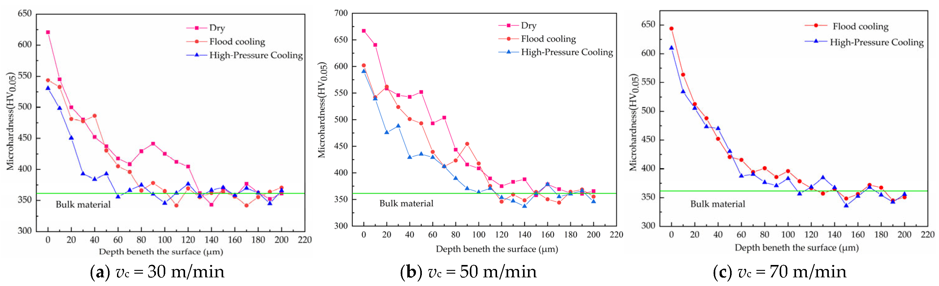
Figure 12 illustrates the variation in microhardness with depth under different cutting speeds and cooling conditions. It can be observed that the microhardness values obtained under all machining conditions are higher than that of the bulk material (361.5 HV
0.05), indicating that significant work hardening has occurred in the surface layer of the workpiece. This hardening behavior is attributed to the combined effects of the high plastic flow rate and the heat generated in the primary shear zone [
16]. In addition, the microhardness gradually decreases with increasing depth and eventually approaches that of the base material.
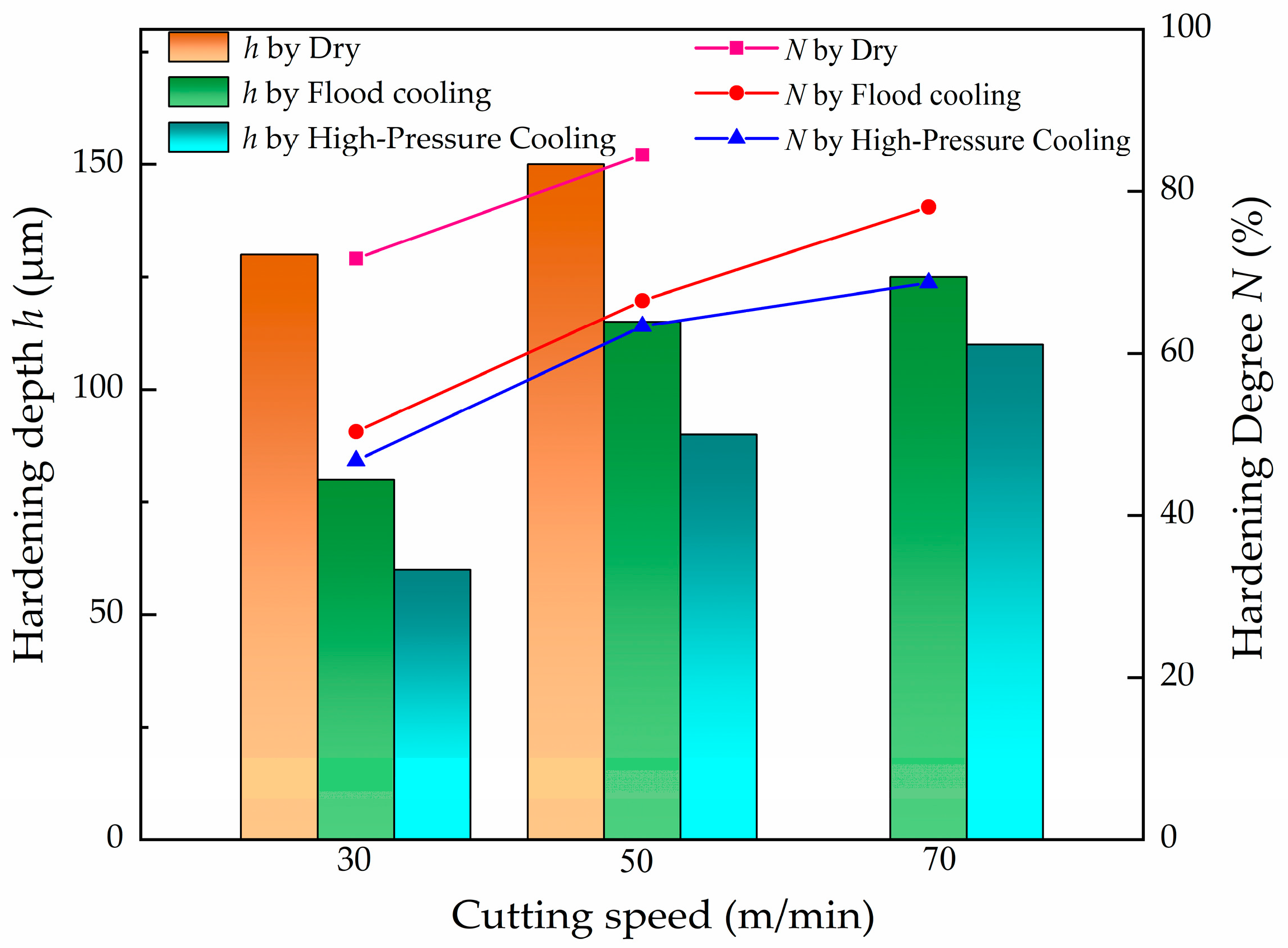
Figure 13 presents the variations in the depth and degree of the work-hardened layer with cutting speed under three cooling conditions. Combined with the results in
Figure 11, it can be seen that dry cutting results in the highest surface hardness, work hardening layer depth, and hardening degree, whereas high-pressure cooling yields the lowest values. For all three cooling conditions, both the depth of the work hardening layer and the hardening degree increase with cutting speed. At cutting speeds of 30 m/min and 50 m/min, the work hardening layer depth under dry cutting is approximately 130 µm and 150 µm, with surface microhardness increases of 71.7% and 84.5% relative to the bulk material. Under flood cooling, the work hardening layer depth is approximately 80 µm, 115 µm, and 125 µm at different speeds, corresponding to surface microhardness increases of 50.3%, 66.5%, and 78.1%. In contrast, high-pressure cooling produces work hardening layer depths of about 60 µm, 90 µm, and 110 µm, with surface microhardness increases of 46.8%, 63.3%, and 68.8%, respectively. These results demonstrate that high-pressure cooling significantly mitigates work hardening in γ-TiAl alloy cutting.
During dry cutting, the absence of cooling and lubrication leads to a markedly increased thermo-mechanical load in the cutting zone, which intensifies stress concentration and plastic deformation. Plastic deformation occurs through dislocation motion, which is hindered by grain boundaries. As the thickness of the plastically deformed layer increases, grain refinement becomes more pronounced. Finer grains introduce more grain boundaries, which restrict dislocation movement, resulting in higher deformation resistance and hardness [
38]. As shown in
Figure 8, dry cutting produces the highest level of plastic deformation and therefore the most severe work hardening. Moreover, more serious tool wear under dry cutting increases material extrusion and friction, further enhancing plastic deformation and hardening of the machined surface. With flood cooling, the cutting fluid reduces the coupled thermal and mechanical effects, thereby lowering surface plastic deformation and work hardening. In the case of high-pressure cooling, the high-velocity jet enhances convective heat transfer and lubrication, which reduces friction and shear resistance at the tool–chip and tool–workpiece interfaces. As a result, heat generation, cutting temperature, plastic deformation, and tool wear are all reduced, leading to a weaker hardening effect and a thinner hardened layer.
Consistent with the results for surface morphology and plastic deformation, increasing the cutting speed under all three cooling conditions leads to higher hardened layer depth and work hardening degree. This trend agrees well with the findings of Ezugwu et al. [
19] and is mainly attributed to the increase in cutting temperature, which enhances the thermal activity of the matrix, as well as the rise in dislocation density caused by plastic deformation.
4. Conclusions
This study investigated the variations in tool wear, surface morphology, surface roughness, surface defects, subsurface microstructure, and microhardness of γ-TiAl alloy under different cutting conditions, evaluating the effects of dry cutting, flood cooling, and high-pressure cooling on machining performance. The main conclusions are as follows:
(1) The primary tool wear mechanism is adhesion, and its severity is strongly influenced by the cooling condition. Dry cutting causes severe adhesion, coating flaking, and minor chipping; flood cooling alleviates adhesion; high-pressure cooling most effectively suppresses tool wear but may induce slight grooving.
(2) Improved cooling significantly enhances machined surface quality. Compared with dry cutting and flood cooling, high-pressure cooling, owing to its superior penetration and lubrication, produces the most favorable surface morphology. At higher cutting speeds (50 and 70 m/min), surfaces machined under high-pressure cooling exhibit the lowest roughness.
(3) Dry-cut machined surfaces exhibit pronounced defects, including feed marks, grooves, material adhesion, and surface tearing. Flood cooling and high-pressure cooling reduce these defects, with high-pressure cooling particularly effective in suppressing material adhesion.
(4) Plastic deformation layers are formed under all three cooling conditions, and their thickness increases with cutting speed. Dry cutting results in the most severe plastic deformation due to insufficient cooling and lubrication. Flood cooling and high-pressure cooling reduce the deformation layer thickness by approximately 39% and 51%, respectively, indicating that high-pressure cooling effectively suppresses material plastic deformation.
(5) Work hardening occurs under all cutting conditions, with the hardened layer depth and hardening degree increasing with cutting speed. Dry cutting produces the most severe work hardening, whereas high-pressure cooling significantly reduces both the depth and degree of work hardening, demonstrating its effectiveness in mitigating machining-induced hardening.