1. Introduction
Gels consist of a three-dimensional, physically or chemically cross-linked polymeric network and a liquid phase (water in the case of hydrogel), dispersed among the meshes and pores of the network [
1,
2]. The liquid content can even exceed 95% by weight [
3].
The interplay between the chemical and physical characteristics of the liquid phase and of the polymeric component determines the properties of the gels and offers the possibility for their fine control. This is achieved by regulating the nature of the chains, their average molecular weight, the degree of cross-linking, and the presence of possible additives such as nanoparticles or drugs, and this makes gels very attractive and interesting for various applications [
4].
Hydrogels, due to their softness, elasticity, and outstanding mechanical properties, have long attracted interest across multiple disciplines—including chemistry, physics, and engineering. Today, they find applications in a wide variety of fields, ranging from sensors [
5] to actuators [
6], with particular relevance in the biomedical sector [
7]. This is especially true for hydrogels derived from biocompatible polymers such as alginate and chitosan.
Hydrogels are often referred to as “smart” materials because they are able to dynamically respond to environmental stimuli [
8]. Their unique characteristics make them suitable for innovations in drug delivery, tissue engineering, wound healing, and more [
9].
Surprisingly, both fundamental and applied research has focused mainly on bulk hydrogels and much less on these materials in the form of films, although the films retain the material’s properties, including high swelling ability, but also display increased stimuli responsiveness and faster responses [
10]. Thin films of hydrogels often exhibit higher stiffness, strength, and stretchability than bulk samples [
11].
There are numerous techniques for the fabrication of hydrogel films [
12]. Generally, as a first step, the preparation requires the formation of a film from precursors, which can be either monomers or non-cross-linked polymers. A solution of these precursors is deposited, and then it undergoes a transition to form the network structure. Among the possible methods for inducing the formation of the film, it is worth mentioning photopolymerization, photolithographic polymerization in single or multiple steps, dip-coating with UV-induced polymerization, and solvent-casting combined with complexation with (poly)electrolytes [
11,
13].
Unfortunately, despite these advantages, the preparation of good-quality hydrogel films is complex, and numerous challenges must be addressed to obtain samples with excellent, uniform, and stable properties. Challenges include the control of swelling and degradation, achieving high mechanical strength, ensuring proper cross-linking, and addressing issues such as phase separation and brittleness [
14]. Furthermore, the selection and preparation of the substrate pose significant challenges and are often time-consuming. Most preparation techniques are not only labor-intensive but also costly and difficult to industrialize or scale up. Therefore, any approach that helps overcome these limitations represents a valuable step forward toward the broader adoption of hydrogel films and their future applications.
In this work, the preparation and characterization of alginate-based hydrogel thin films using a spin-coating technique are presented. This preparation route is simple, economical, and enables us to obtain excellent-quality samples very quickly. In particular, this approach has been employed for the fabrication of alginate-based hydrogels, a material that combines excellent properties with biocompatibility and biodegradability, and is widely used in the biomedical field. Alginate hydrogels are in fact used for wound healing and tissue engineering for the controlled release of drugs and active molecules, since the degree of the cross-linking of the matrix can be precisely controlled [
15,
16,
17].
Spin-coating is a process that is used to apply a uniform film to a flat substrate. Its principle is to deposit a small amount of a solution of the species of interest, in this case alginate, on the substrate, which is then rapidly rotated to distribute the fluid over the substrate by centrifugal force [
18]. The rotation is stopped as soon as the desired thickness is reached. When spin-coating is used for semiconductor, ceramic, or similar materials, the solvent is evaporated, thus enabling the formation of the desired film with a very thin thicknesses, even a few nanometers [
19]. In the case of polymeric materials, factors such as the viscosity of the system must also be taken into consideration; the viscosity of the system increases significantly during the gelation phase.
Sodium alginate is soluble in water and therefore it can be used for the initial solution and gelation can be induced by the substitution of sodium ions by different divalent cations (Ca
2+, Sr
2+, Zn
2+, and others). A physical cross-linking occurs due to ionic bonds between divalent cations and carboxyl groups on alginate [
20,
21]. This route is, in principle, one of the most common and simplest for preparing alginate-based hydrogels. The gelation rate in this case is very high, directly depending on the diffusion rate of the cations in the medium. However, it decreases when the degree of cross-linking and therefore the viscosity increases. For this reason, the samples obtained are often highly inhomogeneous with areas that present different reticulation degree, density, and, consequently, diverse properties.
In the case of thin films, this difficulty can be overcome thanks to the small volume of material involved. On the contrary, the increasing viscosity contributes to the greater adhesion of the film to the substrate and to keeping the thickness under control. Furthermore, it is also possible to use substrates of different nature, such as simple glass slides, and not necessarily specific ones, carefully prepared.
The idea of this work is therefore to obtain an alginate film by spin-coating, depositing a small volume of sodium alginate solution on a substrate and inducing gelation by adding a second solution of calcium salt, while the substrate is rotating. It is also possible to obtain gels loaded with nanoparticles using this route.
Hydrogel–nanoparticle composites are very interesting and promising systems because they can effectively integrate the beneficial properties of both original systems, while minimizing potential adverse effects, especially cytotoxicity. However, the integration of nanoparticles into hydrogels is not a trivial task and it requires the development of methods specifically for this purpose. Nanoparticles can be prepared separately and subsequently dispersed in the gel, or in situ, when possible. In the first case, it can be difficult to avoid distribution gradients within the matrix; meanwhile, in the second case, it is necessary to design appropriate synthesis methods and, often, traces of compounds used as catalysts or byproducts can remain in the system. The method described here has proven to be efficient and very simple also for the preparation of gels loaded with nanoparticles.
In this case, gels loaded with silver nanoparticles were prepared by adding sodium borohydride and silver nitrate to the two solutions, respectively, to exploit the oxidation–reduction reaction in situ. This approach might also be generalizable to other nanoparticles, if it is possible to determine and control their growth conditions or if it is possible to somehow disperse separately prepared particles in the medium.
Several factors can play a role in the formation of films, such as temperature, concentration of the main and additive solutions, and rotation speed of the substrate. For these reasons, the process was conducted using a rotation equal to 100, 500, and 1000 RPM (rotations per minute) to investigate their effect on the film formation, the morphological characteristics, and the particle distribution.
Selected specimens, prepared with this technique, were characterized by optical and scanning electron microscopy (SEM) by UV–Vis and FTIR spectroscopies and X-ray diffraction (XRD) to study the appearance and the general features of these films.
3. Results and Discussion
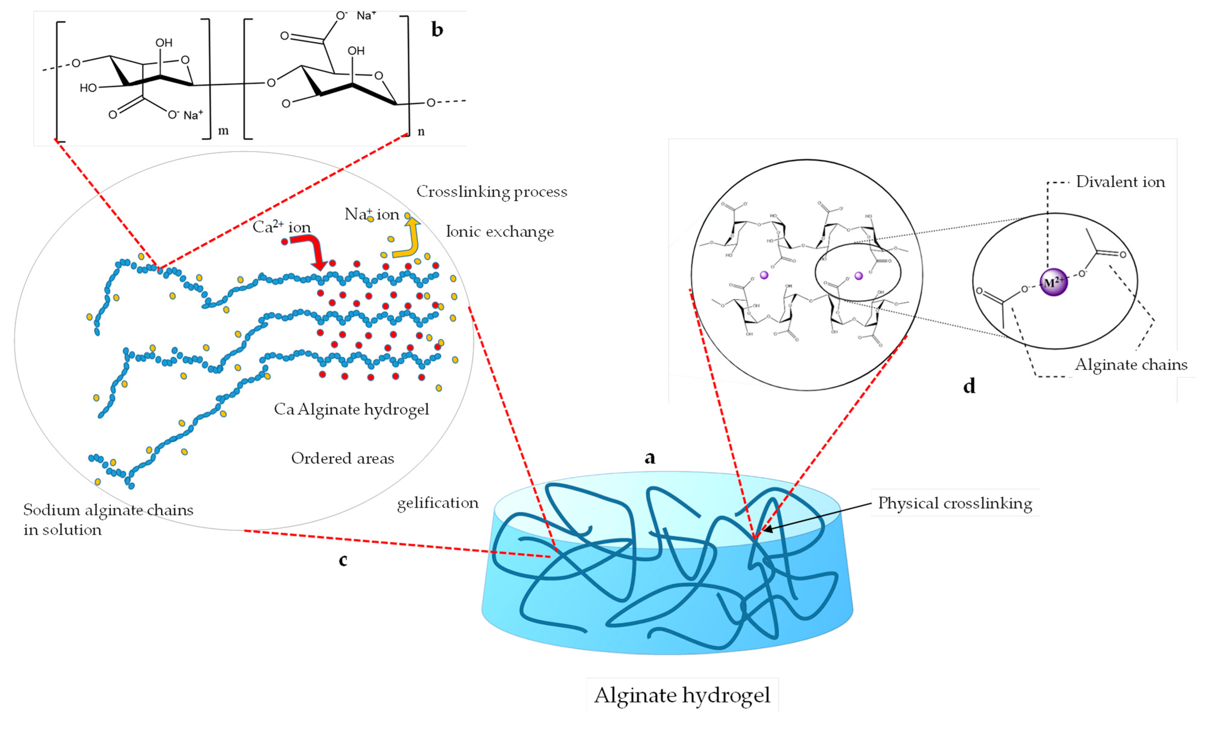
Sodium alginate is a salt of alginic acid, which in turn is a naturally occurring, edible polysaccharide found in brown algae [
20]. This acid is a linear and non-branched copolymer made by randomly distributed blocks of (1→4)-linked β-D-mannuronate (M) and α-L-guluronate (G) residues; these are linked together by strong covalent bonds [
22]. Hydrogels based on alginates are widely studied as a common biomaterial for the bio-fabrication of scaffolds and tissue regeneration and for their favorable properties, which encourage regeneration, cell proliferation, and mechanical strength [
23]. As described above, it is possible to induce the gelation of the chains by replacing sodium ions with ions of higher valence; this is because physical cross-linking occurs due to new ionic bonds that are created. The underlying physicochemical process of gelation is complex. However, a widely accepted model suggests that two opposing G-block sequences interact to form distorted structures and cavities, which can accommodate divalent cations—particularly Ca²⁺—through ionic coordination [
24]. This induces the cross-linking of the alginate chains and creates a junction structure that geometrically resembles an egg box [
25]. Low contents of calcium lead to chain dimerization of alginate chains and, as the concentration increases, the junction zones of different chains associate to form three-dimensional networks.
The G-blocks adopt a “zig-zag”-like helical structure whose cavities represent highly selective sites for the formation of bonds with Ca
2+ ions. The binding of Ca
2+ ions involves four-oxygen coordination [
26,
27]. The gelation process proceeds through several distinct stages, including mono-complexation, dimerization, and lateral aggregation into multimers [
28]. Each of these occurs for the specific concentrations of calcium. It is also well known that too-low concentrations of calcium do not induce gelation at all and that factors such as the molecular weight play an important role; this is because a higher concentration or a molecular weight can lead to a faster gelation process [
25,
27]. Gelation is often very rapid, and this can cause strong calcium concentration gradients, resulting in an inhomogeneous gel; moreover, if the thickness is too high, then the center of the sample may not even gel at all.
Figure 1 shows the chemical structure of the sodium alginate molecule and a schematic representation of the interactions that occur between alginate chains and divalent cations, leading to the formation of physical cross-linking inside the gel.
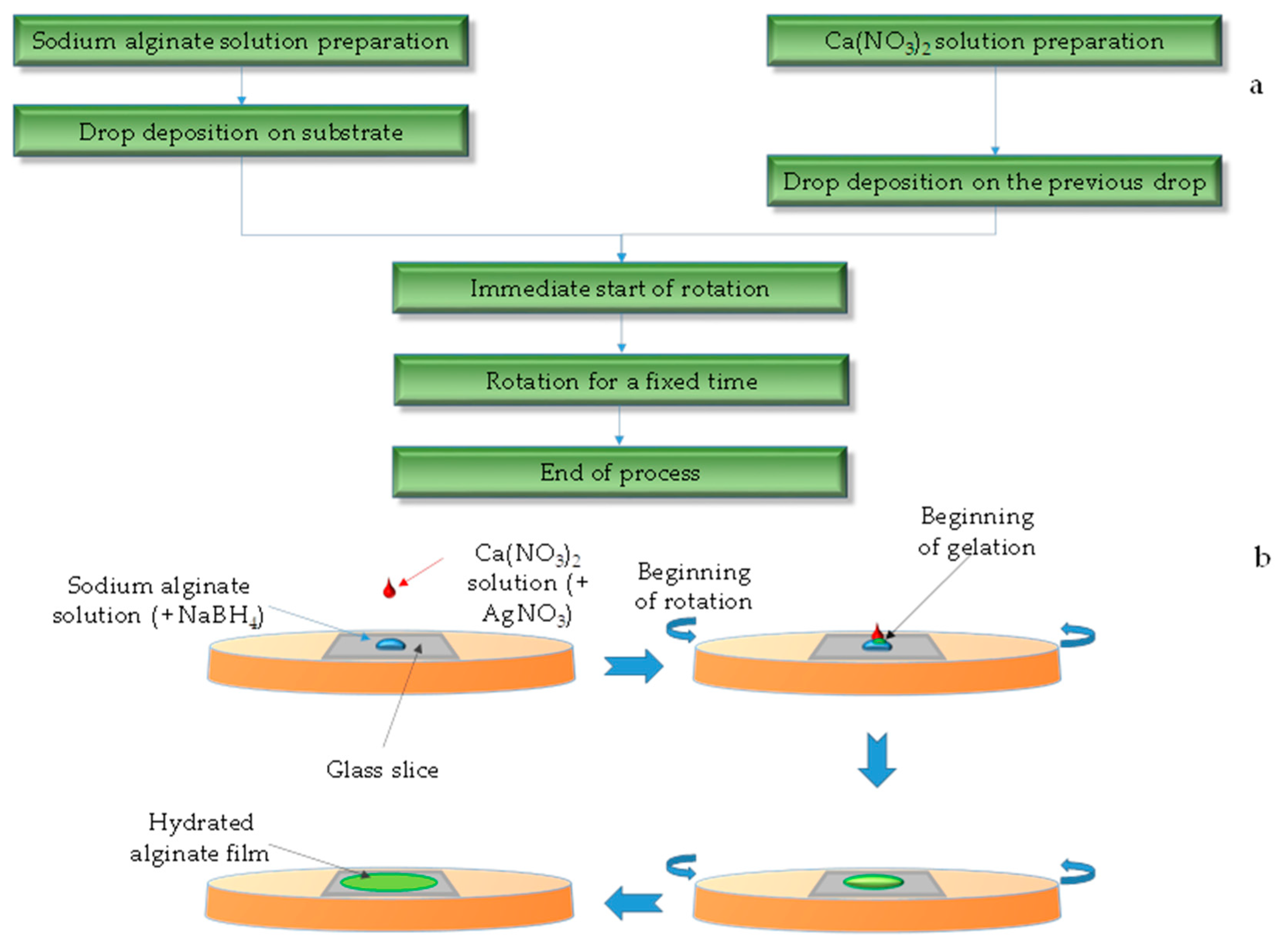
The small volume of the films represents an advantage, as it reduces the concentration gradients and promotes sample homogeneity. For film deposition, gel formation is achieved by dropping sodium alginate and calcium nitrate solutions onto a substrate positioned in a spin-coater, which is operated at a constant speed for two minutes.
While the solutions spread over the supporting substrate, a gelation reaction takes place, forming a compact and well-adherent film on the substrate. Once dehydrated, the film becomes thinner, reaching a thickness measuring less than one micrometer.
Figure 2 shows a schematic representation of the formation of a hydrated alginate film. Interestingly, when the starting solutions contain silver nitrate and sodium borohydride too, silver nanoparticles are simultaneously formed.
In this case, calcium nitrate was used as a source of calcium ions. In principle, calcium chloride—being equally soluble—could have been used for the preparation of pure hydrogels. However, in the presence of silver ions, it leads to the formation of silver chloride (AgCl), a highly insoluble compound. Since the goal was to obtain metallic silver particles, the use of chloride was avoided.
If the two drops of sodium alginate and calcium nitrate solution are brought into contact with the rotation off, a hydrogel bead is quickly formed due to the small volume involved. The wettability of water on glass is high, with a contact angle measuring about 45–47° [
29]. This prevents the liquid from flowing freely on the substrate, together with the surface tension, which increases during gelation. On the contrary, the two isolated solutions are rapidly thrown away by centrifugal force, even at low rotation speeds.
Therefore, the formation of the gel film requires a balance between the viscosity of the liquid medium (which tends to act as an elastic-restoring force, keeping the liquid bubble compact and thick) and the centrifugal force, due to the rotation which instead tends to the sideward spread of the liquid mass.
In general, when the rotation speed is low, the tension force prevails and the droplet does not spread much, contrariwise when the rotation value is set to the upper limit (1000 RPM), the liquid is sprayed away before the gelation is completed. For this reason, the ideal rotation speed is around 500–750 RMP, although this range depends mainly on the concentration of sodium alginate solution. It is worth noting that even the lowest concentration of calcium nitrate used in this study is likely above the minimum required to induce alginate gelation. As a result, the resulting films appear very similar to one another, regardless of the initial calcium nitrate concentration.
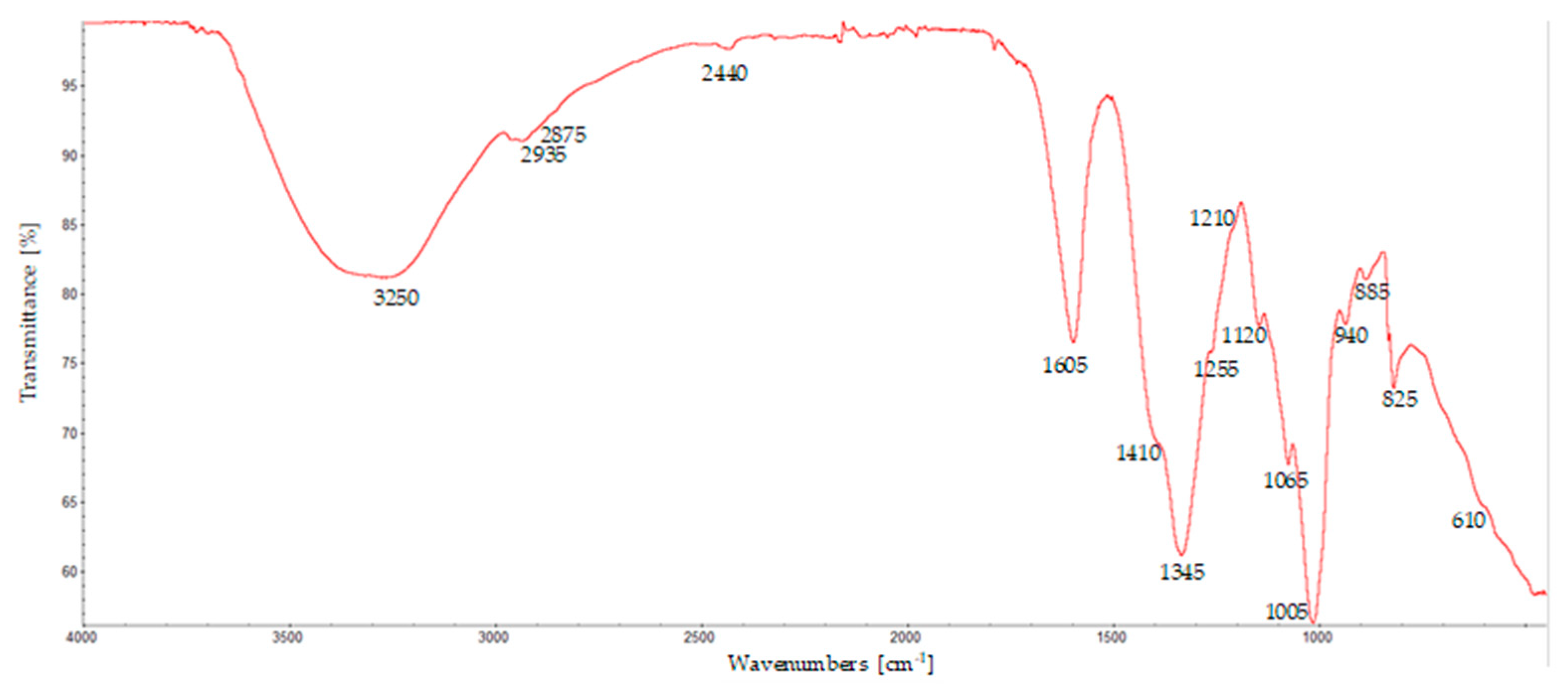
The chemical nature of the film thus obtained was analyzed by FTIR spectroscopy. Vibrational spectroscopic techniques are powerful tools for the non-destructive chemical characterization of materials.
A typical spectrum of these films is shown in
Figure 3 and it is very consistent with what has been reported in the literature [
30], even if the sample has been mechanically detached from the support; this may induce some strain, which can be reflected in the FTIR spectrum, highlighting that the method is effective for the preparation of calcium alginate hydrogels.
The spectrum shows several important features: The first is a very broad band between about 3650 and 3000 cm
−1 and centered around 3250 cm
−1, which is in the region corresponding to the stretching of the OH groups. At about 2935 cm
−1, a band is present due to the antisymmetric stretching of CH; meanwhile, the symmetric mode is weaker at about 2875 cm
−1. Other prominent peaks are found around the following areas: 1600 cm⁻¹, corresponding to the antisymmetric stretching vibration of the carboxylate (COO
-) groups; 1420 cm⁻¹, corresponding to the symmetric COO
- stretching, even if this band appears as a shoulder; 1060 cm⁻¹ C-O stretching. It is worth noting the bands around 1100 and around 1030 cm
−1, which are associated with the presence of guluronic and mannuronic acid residues, respectively. In this case, however, these are not clearly visible and appear rather as a shoulder of the adjacent, more intense peaks. From their relative ratios, it is possible to roughly estimate the ratios of these units in the polymer chains [
31]; in this case, their relative abundances appear rather similar. This ratio is an important parameter because it influences the gelling properties of alginate. When the mannuronic residues prevail, more flexible gels are formed; meanwhile, when the guluronic residues groups are more abundant, they are also more resistant, and rigid gels are formed. Spectroscopic analyses therefore demonstrate that the preparation method is effective. This means that the gelation kinetics are comparable with the parameters imposed by the experimental conditions of the method. The gelation rate depends on factors such as the average molecular weight and the calcium concentration and increases as they increase. This means that careful optimization and regulation of the rotation speed of the substrate in relation to these parameters are necessary.
In this rotational speed range, the films that form have a surface of a few square millimeters, a diameter measuring between approximately 3 and 6 mm, and they are very compact and well-adhered to the substrate. As for the thickness, it is relatively uniform, although it must be noted that the thickness depends on the degree of hydration of the gel. The volume of the films in their fully hydrated state can be more than 40 times the volume of the films in their fully dehydrated state.
However, by elementary geometric considerations, it can be estimated that the newly formed films have a thickness that is slightly over a hundred micrometers, since the additive volume of the two drops of parent solutions is 4 mm3, spreading over a surface of approximately 20 mm2.
Once in a completely dry state, the thickness can decrease in the range 10–50 microns.
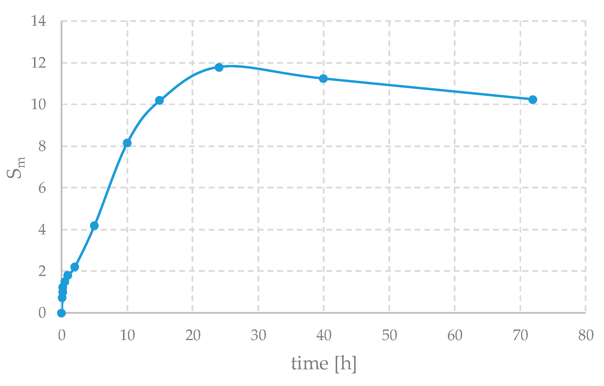
Calcium alginates are well known for their excellent water absorption and swelling capabilities. In fact, their swelling ratio can be as high as 30–50. In this case, due to the constraint of the presence of the substrate that prevents lateral swelling, it is lower, as shown in
Figure 4, reaching only about 12.
The samples were immersed in 40 mL of distilled water to allow absorption. The samples were weighed after fixed intervals.
Swelling, S
m, can be defined as shown in Equation:
where m
f and m
0 are the final and initial masses, respectively.
A small decrease in weight can also be observed after about 24 h; this may be due to a possible partial degradation of the sample and the fact that, gradually, some substances such as sodium nitrate that were initially present can be washed away. Furthermore, the swelling properties of alginate gels are highly dependent on factors such as pH, ionic strength, and the degree of cross-linking; therefore, even similar samples can behave quite differently. Thus, this curve should be seen as qualitative and only indicative of the behavior of these materials. In fact, to reduce experimental error—arising from the difficulty of handling these samples and from procedural issues (for example, mass loss during excess water removal or, conversely, residual water remaining on the surface)—the weight variation should be averaged over multiple samples.
Nevertheless, the swelling ability, together with the IR spectroscopy observations, provides evidence that the preparation method was effective and led to the formation of hydrogels.
The morphological features of the films have been investigated by electronic and optical microscopies.
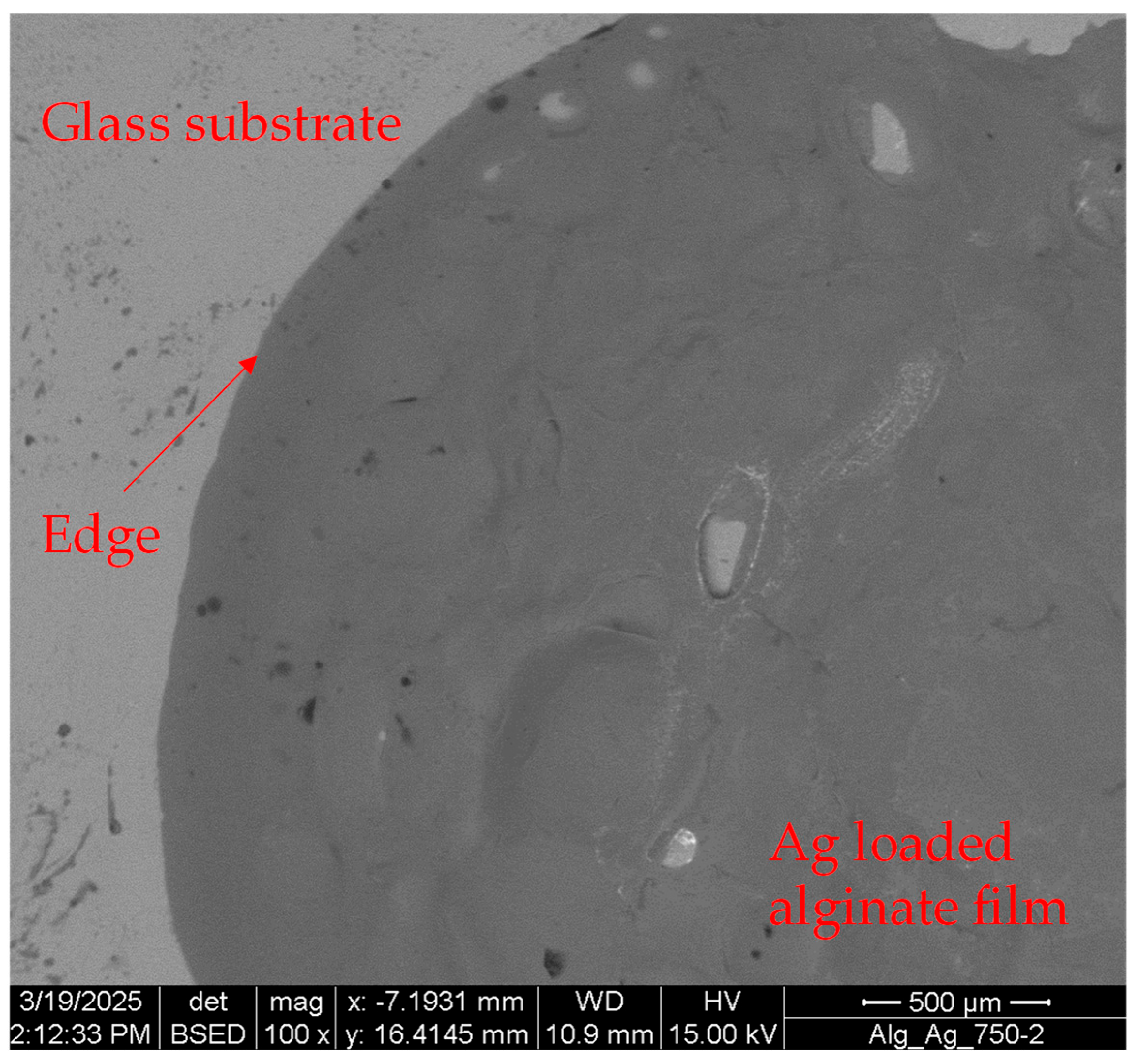
In
Figure 5, an SEM image obtained using backscattered electrons (BSE) is presented. It shows the appearance of an AlgHy
3 sample film obtained with a rotation speed of 750, with a focus on the region near its edge.
The images obtained by the BSE detector show differences in atomic number: the higher the atomic number is, the brighter the material appears in the image. Since silicon has more than double the atomic mass of carbon, in
Figure 4, the bright region is the glass substrate, while the dark one is the hydrogel film.
The film appears to be very uniform, except for a few areas (not shown here) where there are some rips, likely due to the handling of the sample. Furthermore, the film does not appear to be disconnected or in any way raised from the substrate even at its edges, highlighting its good adhesion at the interface with the substrate. The dehydration process certainly induces mechanical stresses in the gel film. Therefore, we cannot completely exclude the possibility that such damages are related these mechanical stresses; however, the polymer matrix is normally very elastic and able to withstand such deformations.
The edge itself also appears very sharp and defined and forms a continuous, clean line, without defective features.
Similar observations can be made by digital optical microscopy.
Figure 6 shows the appearance and profile of a film prepared at 750 RPM and a sodium alginate concentration of 10 g/L and 0.2 M for Ca(NO
3)
2, after three months of aging at room temperature. This film is less than 100 μm thick, and its profile is very uniform in the central part, with height fluctuations of a few micrometers or smaller (
Figure 6a). At the edges, the thickness gradually and uniformly along the entire front decreases to 0, with an angle of about 25° (
Figure 6b).
The smooth slope with which the film degrades is interesting. In fact, it can be reasonably assumed that the film edge profile results from processes that occur during gelation and, once the process is completed, does not change further. The moderate slope of the edge would therefore be a consequence of the interactions between the parent liquid solution and the glass substrate. Since the solution is, in any case, relatively dilute, the interactions are not very different from those between water and glass. In this case, the contact angle, a thermodynamic quantity that describes the angle at the liquid–solid interface, is very modest. A low contact angle indicates a good compatibility between a liquid and the substrate. The solution from which the gel originates spreads well on the glass thanks to favorable interactions, and this could justify the high adhesion of these films to glass, observable both in SEM and in optical tests. However, this should be confirmed through dedicated studies, such as scratch testing. More generally, it would be of great interest to investigate the mechanical properties of these films—such as their hardness and creep—using microindentation experiments. It is conceivable that these properties could be finely tuned by controlling the degree of cross-linking and the chemical nature of the polymer chains, thereby broadening the range of potential applications. Further investigations are needed to study these aspects.
In any case, this observation indicates that gelation occurs throughout the region where the two parent liquids come into contact, uniformly and without gradients from the center to the edges, and that when gelation is complete, the film spreading stops. Therefore, this also means that the preparation route that passes through simultaneous gelation and rotation is effective for obtaining films of hydrogels.
Similar considerations can be made in the case of Ag-loaded gel films, although there are some important differences. They were prepared using optimal conditions for the preparation of unloaded films; only the concentrations of secondary reagents changed. In fact,
Figure 7 shows the typical appearance of the loaded films can be prepared, demonstrating that the method can be effective in this case too.
Ag nanoparticles stem from the redox reaction between silver nitrates and sodium borohydride [
32,
33]. The former compound is commonly used as a starting reagent for this synthesis, while the latter is a well-known reducing agent [
34,
35].
In aqueous solution, it is possible to write the following redox Reaction (1) [
36]:
The presence of boric acid, H3BO3, as a product of this reaction should be viewed formally since the solution chemistry of boron-containing ions and molecular species is complex; numerous equilibria between them can be easily established, without changes to the general stoichiometry of the reaction.
The redox process occurs very quickly once the reagents come into contact. In this case, the reagents are solubilized in the two solutions used to prepare the films.
Since Ag+ ions can be reduced, albeit slowly and inefficiently, also by the free hydroxyl groups of polysaccharides, it is preferable to solubilize them as silver nitrates together with calcium nitrate and sodium borohydride in the alginate solution, so that the reaction begins only when the two liquids come into contact and the rotation starts.
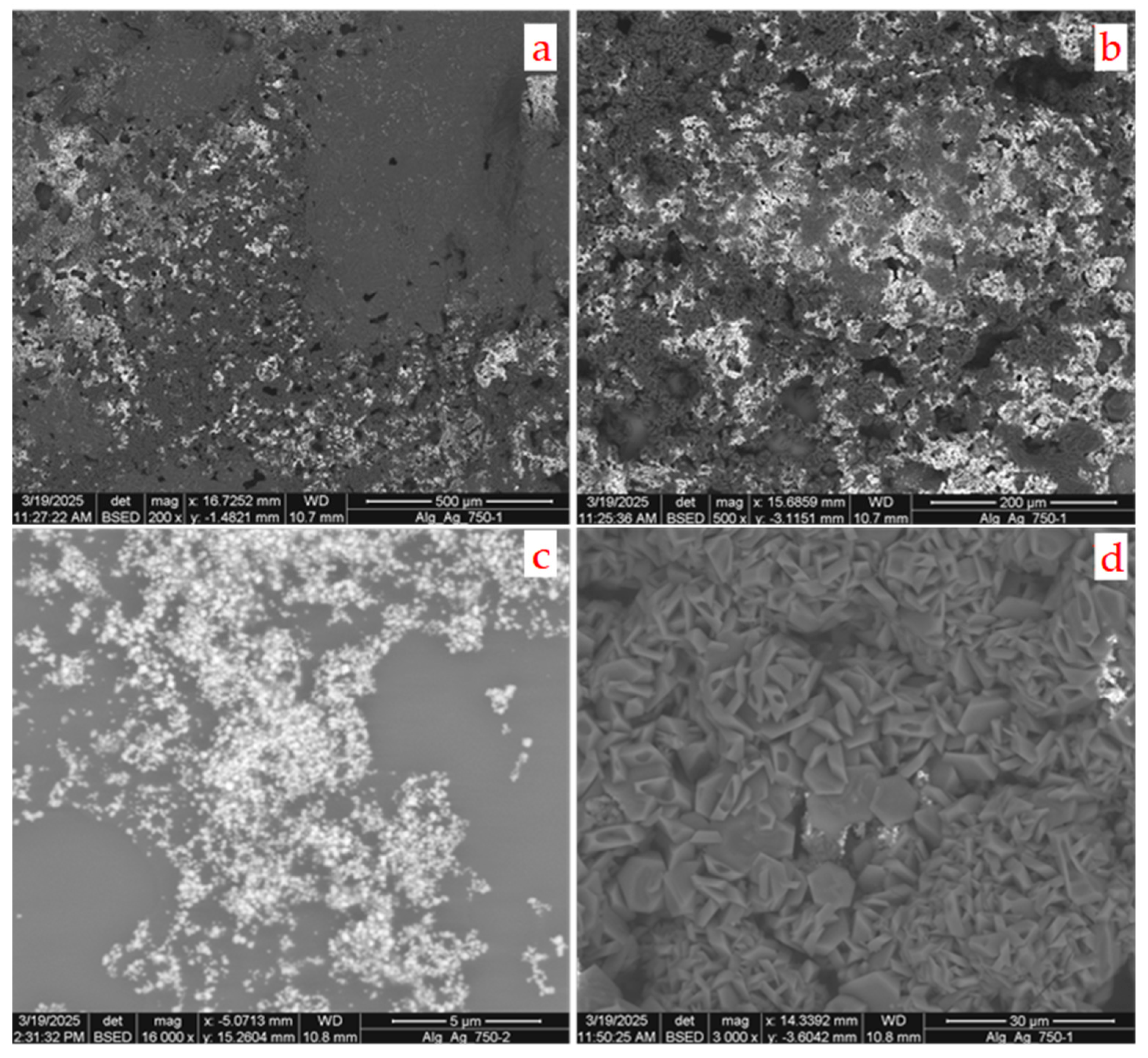
The release of numerous bubbles, due to the formation of hydrogen, occurred for the samples prepared using the solution with the highest borohydride concentration. This has been seen to damage the film during its formation. The SEM analyses detected holes and other defects in the polymer matrices. However, such bubble formation was not observed, or it was at least greatly reduced, in the case of the solution with the lowest concentration.
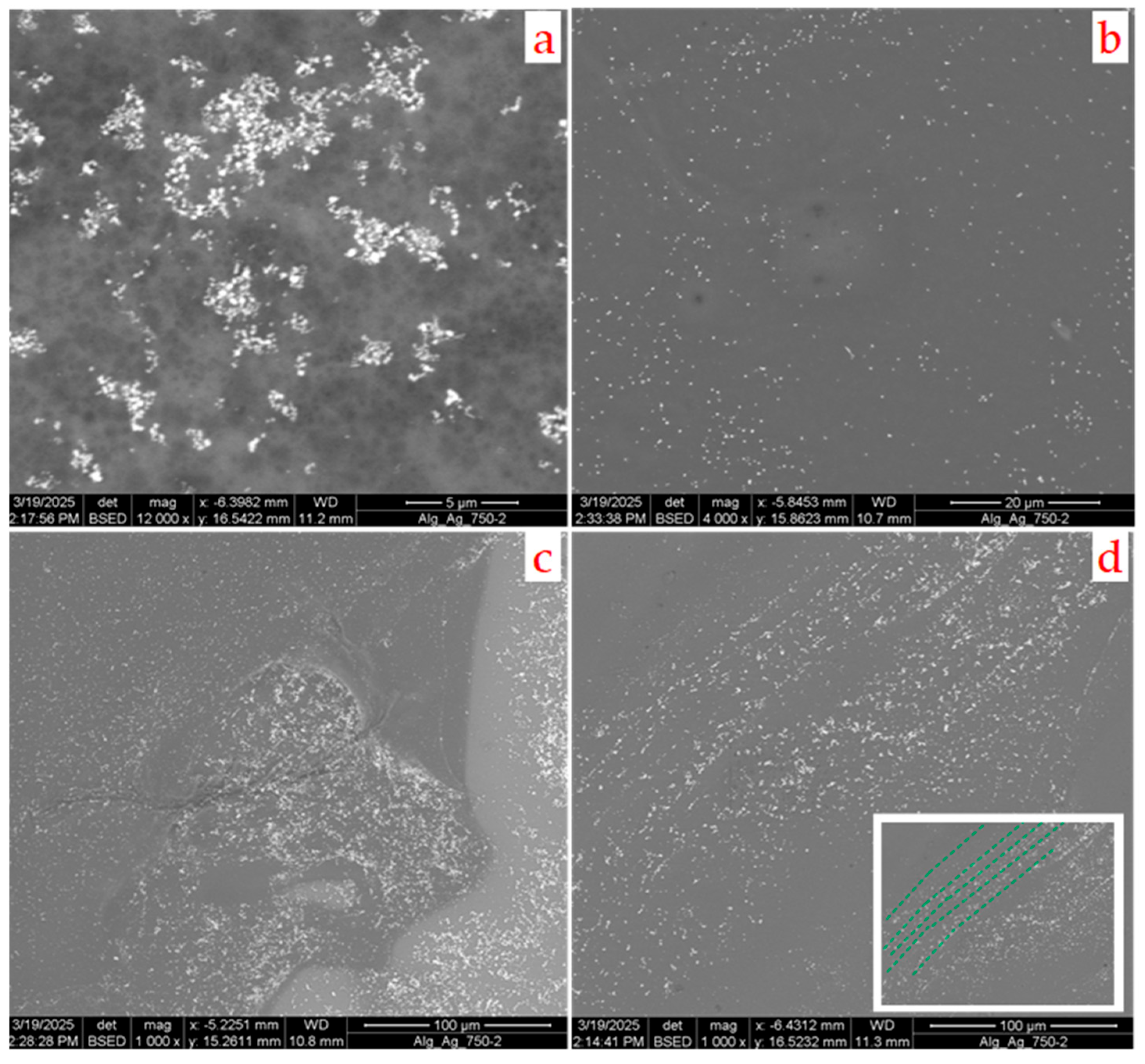
In this case, numerous crystalline particles of average size below 1 micrometer are formed, and they are well-dispersed in the film, as shown in
Figure 8a–d.
The SEM images provide evidence that the most typical morphology of these particles is octahedral; however, there are less abundant morphologies, comprising other shapes—here, rod-like morphologies are the most common.
From the image analysis, in fact, it is possible to establish the dispersion curves of the particle size and evaluate their widths and other characteristics.
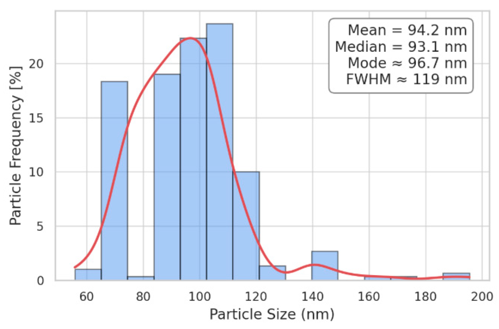
Figure 9 shows the histogram of the particle size distribution curve, obtained by measuring the sizes of 300 particles.
This distribution should be seen as indicative because the method has the limitation of underestimating the number of small particles. Despite this, it turns out that the particles are very uniform in size and that the curve is quite narrow—though it is slightly asymmetric—with a full width at half maximum (FWHM) of around 10–15 nm. Very large particles are rare and most of them are likely aggregates of smaller particles. The peak of the curve is centered around 95 nm.
Most of these particles are isolated inside the gel matrix (as can be seen in
Figure 8b) and the average distance between them is a few microns, but some aggregates or clusters of particles exist where the particle density is much higher. However, in some parts of the film, especially at the edges, the particles tend to align along the lines that are parallel to each other, as can be observed in
Figure 8d (the dotted green lines in the insert of this figure are a guide for the eyes). The distance between these lines, which are not perfectly straight over a distance of a few tens of microns, is quite constant. This suggests that, in these partially ordered regions, the particles form before the local gelation is complete; for this reason, they are dragged by the rotating fluid.
This observation, together with the fact that these particles are very similar in size, can provide some useful clues about the mechanism of their formation. If they appeared at different times during the gelation process or even after it had finished—for example, by the slow diffusion of the reagents through the matrix—a much wider distribution could be expected. The particles nucleated in the early moments of the process would have more time to grow and would become very large, while the later ones would remain small. Conversely, the constancy of their size indicates that they form at the same time in a uniform manner throughout the gel matrix. They form very quickly, as soon as the parent liquids come into contact, when the gelation process is still in its embryonic stage. For this reason, when the gel begins to cross-link at the periphery of the sample, the liquid, the viscosity of which gradually increases, drags them along with it.
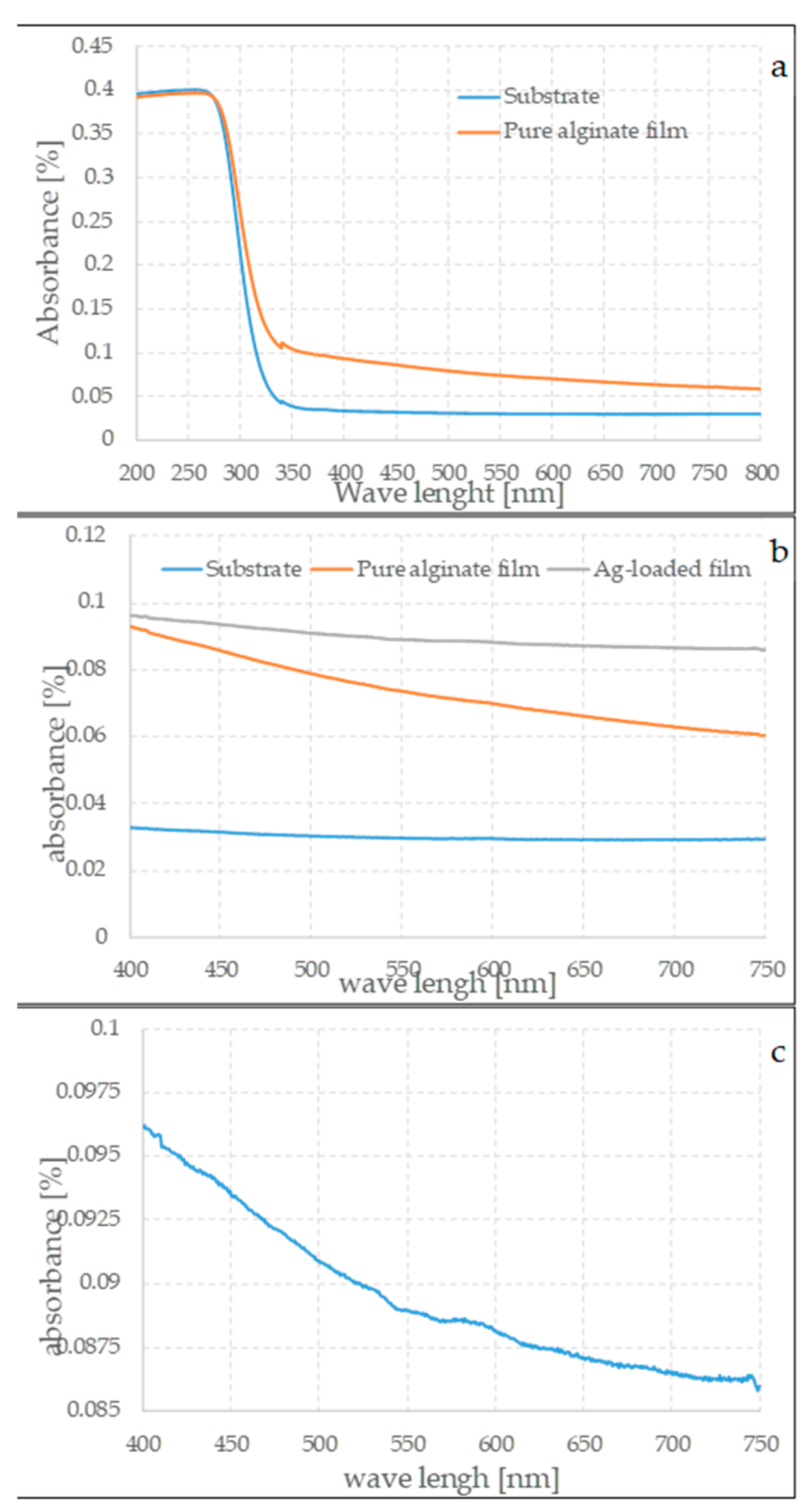
To obtain relevant insights into the pure and loaded films produced by this method, the films were characterized using UV–Vis spectroscopy. This is a powerful tool for analyzing metal nanoparticles [
37] and provides information on factors such as their size, morphology, and aggregation. Indeed, due to the localized surface plasmonic resonance, the UV–Vis spectra of silver-based nanosystems are characterized by the high absorption of photons in the range between about 200 and 900 nm.
Figure 10a–c show the spectra of the substrate, parent, and loaded films. The spectra were obtained by directly measuring the absorption of the samples placed along the optical path of the beam.
As can be seen in
Figure 10a, the substrate has almost-negligible absorption for wavelengths above about 350 nm, but the absorption is very strong below 300 nm. Although the absolute value depends on the thickness of the substrate, this wavelength dependence of UV absorbance is characteristic of borosilicate glasses [
38]. This strong absorption is the dominant feature in this part of the spectrum. However, the processed samples show significantly higher absorption than the substrate alone in the range between 400 and 800 nm. This behavior can only be attributed to the presence of a compact film. No significant differences are evident between the spectra of the samples prepared with varying experimental conditions in the range in which the films form; this observation suggests that they do not particularly influence the final thickness, but the silver-loaded samples are less transparent. It is interesting to note that the sample containing silver particles has a weak and not very well defined hump between about 500 and 600 nm, as can be seen in
Figure 10c. The aqueous dispersions of silver nanoparticles have an absorption maximum between 300 and 700 nm, depending on several factors, such as the size of the particles, their morphologies, their formations, and their concentrations. These measurements should be considered qualitative; however, due to the nature of the samples, in particular due to their very small mass, it should be taken into account that particles with sizes of around 100 nm [
39,
40] have a maximum mass that is in approximately the same range as that observed for the films. This is not in disagreement with the observations made with the electron microscope.
Similar observations can be made by changing most of the experimental parameters, i.e., the rotation speed or the ratio between the concentration of sodium alginate and calcium nitrate. The formation of the films, in both cases of pure and of loaded films, is controlled by the gelation process; once cross-linking is completed, the matrix is no longer able to spread on the substrate. Therefore, there are a few differences between the gels that can be obtained by changing the experimental parameters.
However, when the concentration of the reducing agent is high, important differences occur. The lively and intense release of hydrogen observed at the beginning of the process disturbs the film formation and damages its structure.
Numerous holes and rips in the matrix texture are observed, as can be seen in
Figure 11a,b.
Molecular hydrogen is one of the co-products of reaction 1 and this is present in a ratio of 7:2 with sodium borohydride. Therefore, a non-negligible volume of molecular hydrogen is released. If the initial concentration is low, then the bubbles that form are few and small. On the contrary, when the concentration is high, these bubbles can grow quite a lot. They damage the gel matrix while it is forming, and this implies that the samples obtained in this way could not be usable and that the nanoparticles could escape from the film.
Indeed, numerous crystalline silver particles—similar to those observed in the previous case—are also present here, but at a significantly higher concentration (
Figure 11c). In this case, instead of being mostly isolated—as was the case when the concentration of the reducing agent was lower—the particles are found preferentially in clumps and clusters, which is likely because of the extremely rapid and uncontrolled nucleation. Above all, numerous other crystals are present, due to various inorganic phases (
Figure 11d), suggesting a different chemical path.
These crystals have a tabular hexagonal formation and are rich in boron. Among the possible phases, boric acid and metaboric acid should be mentioned; these can be formed, together with sodium nitrate, during the oxidation–reduction reaction between silver nitrate and sodium borohydride. However, since sodium is also present, the most probable compound is borax, Na2B4O7*10H2O. While silver nanoparticles are obviously insoluble, these two compounds are soluble in water. Therefore, they are initially dissolved in the water dispersed between the polymer meshes of the gel. When the synthesis is performed using a low concentration of sodium borohydride, their concentration is also negligible; moreover, any crystals that form by precipitation when the water is removed from the film are few, small, and difficult to detect. When the concentration of the reducing agent is high, the concentration of these compounds also increases; consequently, a greater number of crystals can be detected. Boric acid is also much less soluble in water at low temperatures than it is at high temperatures, thus favoring the growth of these crystals.
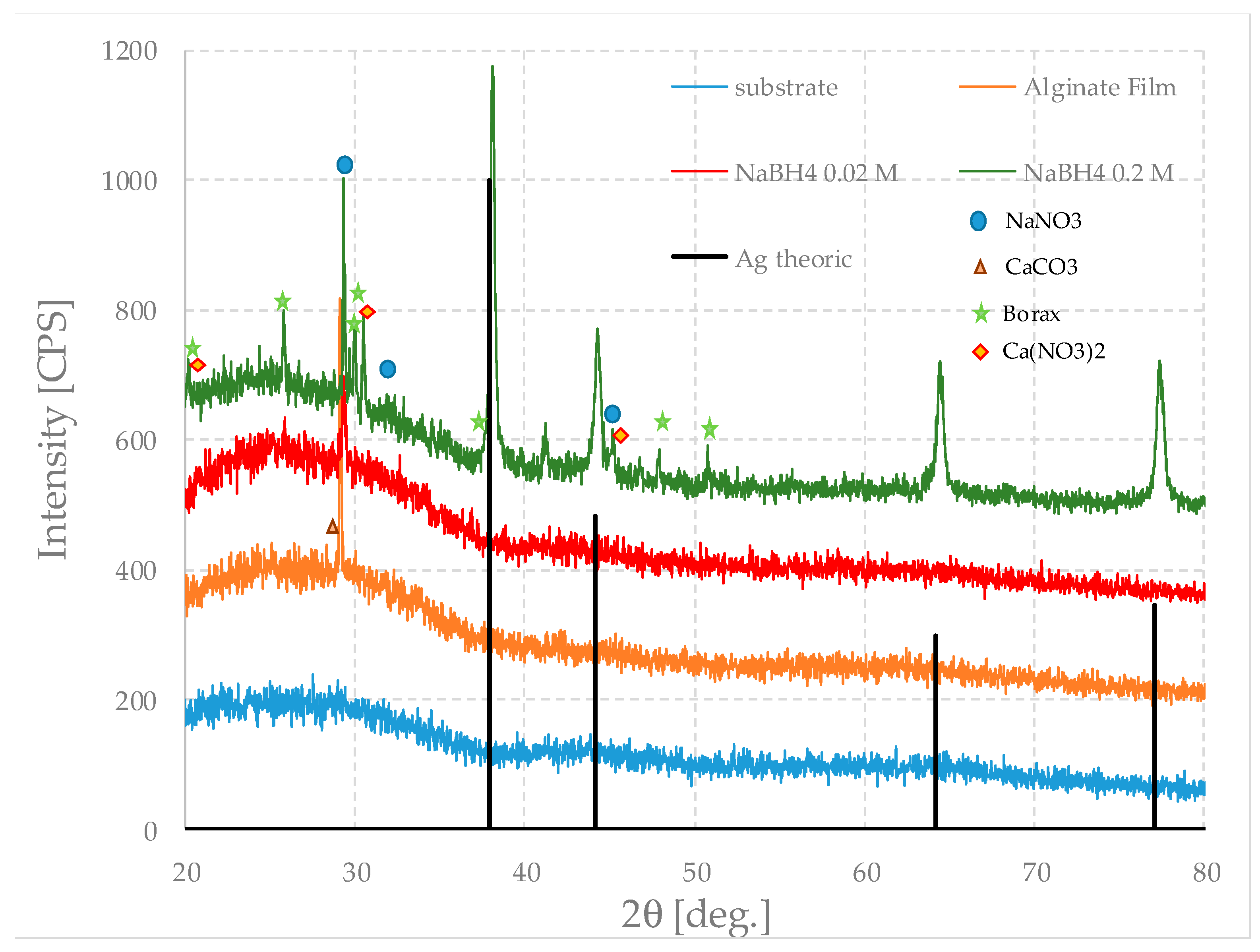
To gain further insight into the nature of these particles and the crystalline phases present and to gain structural information on the film, they were analyzed by XRD diffraction.
Figure 12 shows the XRD patterns of the pure film and those loaded with silver particles, prepared using different concentrations of sodium borohydride, and that of the substrate as a reference. For clarity, only the theoretical pattern of silver is shown; however, the peaks, marked by symbols, are recognizable due to other inorganic crystalline phases (including, somewhat surprisingly, calcite, CaCO
3). This may conceivably derive from the later alteration of calcium nitrate, whose peaks are in fact rather weak.
All the curves have a modest intensity and are very noisy, both due to the nature of the material and the fact that the analyzed mass is, in itself, very small.
The pure-alginate film is, as expected, amorphous and does not show any peculiar characteristics; on the contrary, it follows the diffractogram of the substrate quite well, which is also amorphous. Since the film is thin, their relative intensities are not very different either.
However, in the case of the pure film, a relatively intense peak associated with calcium carbonate is evident. This is—regardless of its origin—quite surprising; the calcite probably derives from the initial presence of calcium nitrate by subsequent precipitation. This means that calcium nitrate was present in a small excess in respect to the value needed to achieve complete gelation; therefore, the film formation parameters and the compositions of the starting solutions can still be optimized.
In the film prepared with the highest amount of sodium borohydride, the peaks of silver nanoparticles represent the main feature that can be noticed; they are not so evident in the other sample. This is due to a much lower concentration that leads to a lower intensity, which is barely distinguishable from the noise of the diffractogram.
In the first sample, it is also possible to recognize the presence of other phases that initially remain in the solution but crystallize when the sample loses its water. A small quantity of sodium nitrate can be present and among the boron-based phases, and borax is the one that best fits the peaks. Metaboric acid and boric acid may be also present, but in very small concentrations. Borax forms because of the relatively high concentration of Na
+ ions, which arise both from the reaction of sodium borohydride and from the substitution of calcium ions between the alginate chains, according to the following Reaction (2):
This reaction could also explain the fact that the peaks associated with sodium nitrate are very weak. In fact, it would be consumed while borax is formed.
The oxidation–reduction reaction is exothermic, and borax is more soluble in water at high temperatures, so it can be imagined that, in the first moments, the concentration of the crystals is low. However, since the mass of the sample is small, it cools very quickly, inducing conditions of supersaturation within the matrix just as quickly. Therefore, the crystals begin to precipitate simultaneously, and their size is uniform.
In all cases, these compounds are, unlike silver, very soluble in water. Therefore, in principle, they could be removed by a series of washing and desiccation cycles; but silver nanoparticles could also escape from the matrix following this treatment. Accordingly, in this study, the authors preferred not to conduct this treatment.
The good agreement between the analyses performed with the electron microscope and those of diffraction positively show that it is possible to obtain alginate films and that it is also possible to load them with silver nanoparticles.


 ,
, 


