Article

Preparation of Transparent MTMS/BNNS Composite Siloxane Coatings with Anti-Biofouling Properties

School of Marine Engineering Equipment, Zhejiang Ocean University, Zhoushan 316022, China
*
Author to whom correspondence should be addressed.
Coatings 2025, 15(7), 769; https://doi.org/10.3390/coatings15070769
Submission received: 11 June 2025 / Revised: 26 June 2025 / Accepted: 27 June 2025 / Published: 29 June 2025
(This article belongs to the Special Issue Advanced Polymer Coatings: Materials, Methods, and Applications)

Abstract

With the rapid development of marine renewable energy, especially offshore photovoltaic systems, the problem of biofouling of photovoltaic equipment in the marine environment has become increasingly prominent. The attachment of marine organisms such as algae will significantly affect the photoelectric conversion efficiency of photovoltaic panels, thereby reducing the stability and economy of the system. In this study, a composite siloxane coating was designed and prepared. Methyltrimethoxysilane (MTMS) was used as the organosilicon component. The negative potential of the coating was significantly enhanced by incorporating hexagonal boron nitride nanosheets (h-BNNS). This negative potential and the negative charge on the surface of marine organisms, especially algae, would produce electrostatic repulsion, which can effectively reduce the attachment of organisms. The results show that the prepared coating exhibits excellent performance in anti-biofouling, adhesion, chemical stability, transparency, and self-cleaning properties. The transparency of the coating reached 92.7%. After immersion with Chlorella for 28 days, the coverage percentage on the coating surface was only 0.98%, while the coverage percentage on the blank sample was 23.25%. The corrosion resistance and salt resistance of the coating also ensure its stability in complex marine environments, and it has broad application prospects.

Graphical Abstract

1. Introduction

With the rapid rise of the global marine economy, the development and utilization of marine resources, especially in the field of marine renewable energy, has become an important driving force for energy transformation and emission reduction [1]. As an efficient and green energy conversion method, offshore solar photovoltaic systems have important potential in reducing greenhouse gas emissions and improving energy self-sufficiency [2]. Compared with terrestrial photovoltaics, offshore photovoltaics have more efficient energy conversion capabilities and less land area [3,4,5]. However, they face more severe natural environmental challenges and have to contend with the impact of marine biofouling [6]. Long-term exposure to the marine environment makes the surface of photovoltaic panels susceptible to the attachment and growth of various marine organisms, such as algae, shellfish, and other microorganisms. The attachment of these organisms will not only reduce the photoelectric conversion efficiency of photovoltaic panels, but also accelerate the corrosion and aging of equipment, thereby increasing maintenance costs and shortening the service life of equipment [7]. Therefore, enhancing the ability of photovoltaic equipment to resist biofouling has become a key factor in improving the long-term stability and economy of offshore photovoltaic systems.
Currently, the technology to solve the problem of marine biofouling is mainly focused on coating materials. Although traditional antifouling coatings can effectively prevent biological attachment, they are often susceptible to the combined damage of water scouring and ultraviolet radiation, causing the performance of the coating to rapidly decline. In addition, since these coatings usually contain chemicals that are harmful to the environment and ecosystems, such as organic tin and copper-based compounds, their use is gradually restricted by strict environmental regulations and is being replaced by more environmentally friendly antifouling coatings [8,9,10], including photocatalytic coatings [11,12,13], superhydrophobic coatings [14,15,16], and biomimetic coatings [17,18,19]. These innovative antifouling technologies have demonstrated significant potential in enhancing biofouling prevention. However, offshore photovoltaic coatings must also withstand harsh saline conditions, constant mechanical abrasion from wave action, and stringent optical-transparency requirements. While existing antifouling strategies show promise, they rarely satisfy all the optical, mechanical, chemical, and environmental criteria simultaneously. Therefore, it is necessary to prepare an antifouling coating with high visible light transmittance, strong mechanical durability, and long-term chemical stability in the marine environment, which is specially designed for offshore photovoltaic applications.
The silicon–oxygen bond (Si-O) and siloxane structure (Si-O-Si) in silicon-based materials provide them excellent chemical stability, low surface energy, and self-cleaning properties. Therefore, silicon-based materials are considered to be ideal for long-term and effective antifouling [20]. Sun et al. [21] introduced benzothiazole groups into PDMS chains through disulfide exchange reactions to fabricate a self-healing silicon-based coating. The disulfide bonds provide the coating polymers excellent toughness, high stretchability, and self-healing properties. Similarly, An et al. [22] enhanced the mechanical strength of the silicone coating through the synergistic effects of hydrogen bonding, π-π aromatic interactions, and covalent bonding, while ensuring a high anti-biofouling performance of 99.1% antibacterial rate. Lu et al. [23] synthesized an amphiphilic hydrogel coating with silicon-containing epoxy resin as the hydrophobic part and silver nanoparticles (AgNPs) as the hydrophilic part. However, ordinary organosilicon antifouling coatings have the disadvantages of a poor static antifouling effect and low mechanical properties. In recent years, hybrid materials have been widely used in various fields because they take advantage of the advantages of both organic and inorganic components. Boron nitride nanosheets (BNNS) are two-dimensional nanomaterials with a graphene-like structure that have excellent mechanical properties, hydrophobicity, chemical inertness, and non-toxicity [24]. When nanoscale boron nitride is introduced into the coating, it can not only improve the mechanical properties and chemical stability of the coating, but also enhance the self-cleaning properties of the coating. Studies have shown that when boron nitride is dispersed in water, its surface exhibits a negative potential [25,26]. At the same time, due to the presence of carboxyl and amino groups, the surface of seaweed is usually negatively charged [27,28]. This provides us with an idea of using electrostatic repulsion as an antifouling method.
Based on this mechanism, this study designed and prepared a composite siloxane antifouling coating. Methyltrimethoxysilane (MTMS) was used as the organosilicon component, and the negative surface potential of the coating was significantly increased by introducing boron nitride nanosheets. The electrostatic interaction between this negative potential and the surface of seaweed can effectively reduce the adsorption of seaweed on the coating surface, thereby obtaining excellent antifouling performance. At the same time, the coating also has a high degree of transparency and excellent self-cleaning properties, and maintains a certain chemical stability in salt solution. This composite siloxane antifouling coating has broad application prospects in the field of offshore photovoltaics.

2. Materials and Methods

2.1. Materials

Smooth glass slides (model 7101, thickness 1.0 mm) were used as substrates and were purchased from Yancheng Yufan Experimental Equipment Co., Ltd. (Yancheng, China). Methyltrimethoxysilane (98%) and sodium hydroxide (AR, 85%) were purchased from Shanghai Aladdin Biochemical Technology Co., Ltd. (Shanghai, China). Isopropanol (AR, ≥99.5%) was purchased from Shanghai Macklin Biochemical Co., Ltd. (Shanghai, China). Hydrochloric acid (AR) was purchased from Sinopharm Chemical Reagent Co., Ltd. (Shanghai, China). Hexagonal boron nitride nanosheets were purchased from Jiangsu Xianfeng Nanomaterials Technology Co., Ltd. (Nanjing, China), and glutaraldehyde was purchased from Shanghai Yien Chemical Technology Co., Ltd. (Shanghai, China). The deionized water was prepared by a laboratory pure water machine (GREEN Q3-20T, EPED, Nanjing, China). The artificial seawater was prepared according to the ASTM D1141 standard [29]. Chlorella sp. was obtained from Qingdao Kangyuan Microalgae Biotechnology Co., Ltd. (Qingdao, China). Natural seawater was collected from Qitou Ocean and filtered through 0.45 μm filter membrane.

2.2. Anti-Biofouling Coatings Preparation

The experiment used MTMS to undergo a hydrolysis reaction under acidic conditions to generate silanol, which was further formed into siloxane through a polycondensation reaction: First, MTMS (7.96 mL) was added to Isopropanol (IPA) (50 mL) and stirred with a magnetic stirrer. Then, hydrochloric acid (HCl) (1.11 mL) was added dropwise, followed by the addition of 0.1 wt% of hexagonal boron nitride nanosheets (h-BNNS). After stirring at 400 rpm at room temperature for 2 h, a white coating suspension was obtained. Figure 1 shows the preparation process. The glass slide was pretreated before coating using an ultrasonic cleaner with deionized water for 30 min to remove surface impurities, and the glass slide was placed in a drying oven to remove moisture. The coating solution was sprayed onto the substrate at a pressure of 0.7 MPa and a distance of 10 cm from the glass slide and then cured at 120° for 30 min. The spray curing process was repeated three times to obtain a glass sample with a coating. The thickness of the coating was 310 nm (Figure S1). The pure MTMS-based coating sample is hereafter denoted as MTMS, and the composite coating containing h-BNNS is denoted as MTMS/BNNS.

2.3. Characterization

The surface morphology and thickness of the samples was analyzed using a field emission scanning electron microscope (FE-SEM, Sigma500, Carl Zeiss AG, Jena, Germany) with an Energy Dispersive X-ray Spectrometer (EDS). Since the samples were non-conductive, they needed to be gold-sprayed in a vacuum environment before SEM and EDS testing. Atomic Force Microscopy (AFM, Bruker Dimension Icon, Ettlingen, Germany) was employed to further observe the surface morphology of the coatings and obtain roughness data. The lattice structure of the samples was recorded using a high-resolution transmission electron microscope (HRTEM, FEI Talos F200X G2, Thermo Scientific, Waltham, MA, USA). Surface functional group changes were analyzed using X-ray photoelectron spectroscopy (XPS, K-Alpha, Thermo Scientific, Waltham, MA, USA) and Fourier-transform infrared spectroscopy (FTIR, Nicolet iS20, Thermo Fisher Scientific, Waltham, MA, USA). X-ray diffraction (XRD, DX-2700BH, Haoyuan, Dandong, China) data of the samples were collected using an X-ray diffractometer. Raman spectra of the samples were obtained using a laser confocal Raman spectroscopy system (XploRA, Horiba, Kyoto, Japan). The contact angle (CA) of the coated glass surface with a 5 μL deionized water droplet was measured using a contact angle meter (SZ-CAMB3, Sunzern, Shanghai, China), and the average value of the results at three different locations of the sample was taken as the data. Finally, The attachment of algae was observed and recorded using an optical microscope (DM750, Shanghai, China).

2.4. Adhesion and Chemical Stability Test

The adhesion test was based on the ISO2409 standard [30]. A sharp blade was used to cut the sample surface at intervals of 2 mm, with a total of 6 cuts in the horizontal and vertical directions. The coating surface was cleaned with a soft brush after cutting. After the sample preparation was completed, the center of the tape was placed on the grid and the tape was rubbed with fingers on the cut area to ensure that the tape adhered evenly. The free end of the tape was grasped and quickly torn off the tape at an angle of 60° within 0.5 to 1 s to observe the coating shedding condition. For the chemical stability test, the coated glass samples were immersed in 0.1 M HCl, NaCl and 0.1 M NaOH solutions with different pH values for 24 h, 48 h, and 72 h [31], respectively, and then the samples were dried in air and the contact angles were measured. Three parallel samples were set up for each experiment.

2.5. Anti-Biofouling Test

In the anti-biofouling test, Chlorella was cultured in artificial seawater and BG11 as culture medium in a light incubator (SPX-150BIII, Faithful, Cangzhou, China) with a light/dark time ratio of 12 h/12 h. The samples were immersed in the culture medium containing Chlorella for 1 day, 7 days, and 31 days. After the samples were taken out at the specified time, they were placed in glutaraldehyde (3%, solvent is water) for 1 h, which is conducive to fixing the fouling organisms attached to the sample surface [32]. The sample surface was then rinsed with artificial seawater to remove excess glutaraldehyde, and this was repeated 3 times to ensure complete removal, before letting it air dry naturally after cleaning. Finally, an optical microscope was used to observe the algae attachment on the sample surface. Three parallel samples were set up for each experiment. Microscope images were binarized in ImageJ v1.54g by thresholding the green autofluorescence channel to distinguish cells from the background. The software then computed the ratio of cell-covered pixels to total pixels, yielding the coverage percentage.

2.6. Zeta Potential Measurement

The zeta potential analyzer determines the surface electrical properties by measuring the charge distribution in the liquid near the surface of a particle or material. Its working principle is based on the double layer formed by the charges on the surface of the particle in the liquid medium. When an electric field is applied, the charged particles in the double layer will move, resulting in electrophoretic flow. The zeta potential can be calculated by measuring the potential difference between two electrodes around the sample. This process can reflect the charge properties of the sample surface and the liquid interface. The zeta potential was determined using a nanoparticle size and potential analyzer (Zetasizer Nano ZS, Malvern Panalytical, Malvern, UK). After the coating was prepared, the sample was cooled at room temperature and then scraped off the substrate with a clean blade. The resulting particles were ground and dispersed into filtered natural seawater (pH 8.1) by ultrasound. After standing for 24 h, the upper suspension containing the dispersed particles was taken for zeta potential measurement. The use of filtered natural seawater ensured that the pH value matched real ocean conditions, as pH directly affects the testing of the zeta potential [33]. Three measurements were performed for each sample, and the average of these data was used as the final result.

3. Results and Discussion

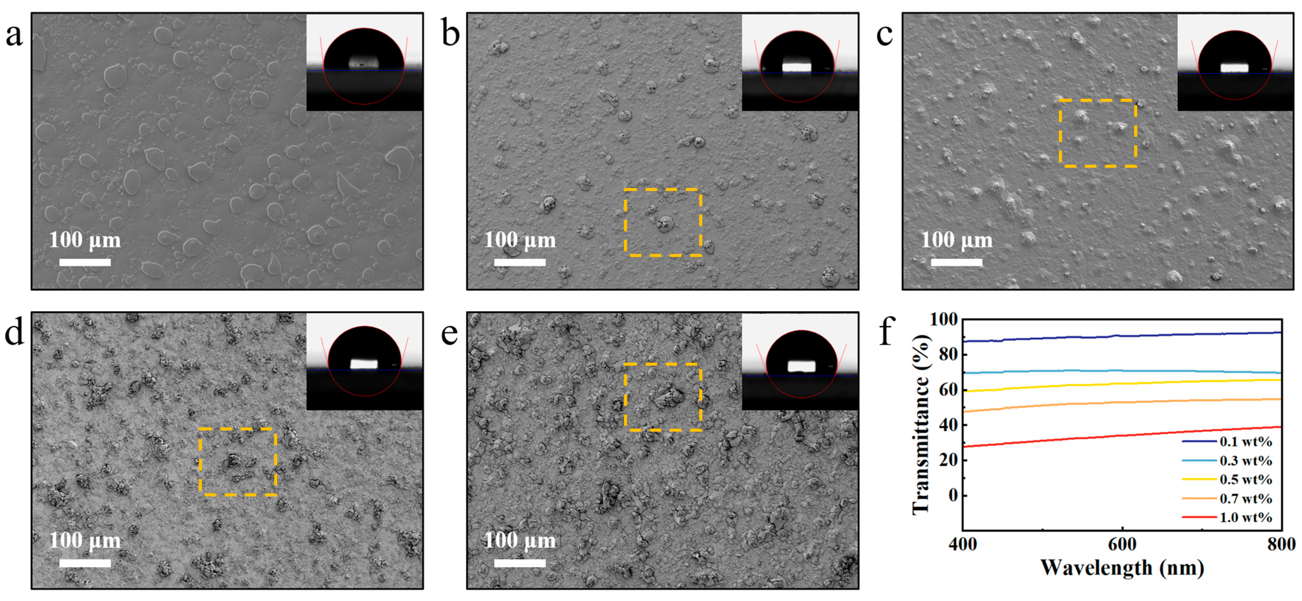
3.1. Effect of BNNS Loading on Transparency and Hydrophobicity of Coatings

According to the Wenzel model, surface roughness affects wettability, and the hydrophobicity of a hydrophobic surface increases with increasing roughness [34]. Increasing the content of BNNS can enhance the hydrophobicity of the coating. However, excessive BNNS content will cause agglomeration and cause a significant decrease in the transparency of the coating. Therefore, it is crucial to find the right balance between transparency and hydrophobicity if the coating is to be successfully applied in the photovoltaic field.
Figure 2 shows the SEM images, contact angles, and transparency of coatings with different BNNS contents. When the BNNS mass was 0.1 wt% (Figure 2a), the two-dimensional flake BNNS on the coating surface was evenly dispersed, the CA of the coating was 95.9°, and the transparency reached 92.7%. When the BNNS mass was 0.3 wt% (Figure 2b), the BNNS on the coating surface had begun to agglomerate on a small scale (yellow box), the CA increased to 100.1°, and the transparency dropped rapidly to 71.1%. Obviously, the increase in BNNS increased the surface roughness of the coating, but due to the appearance of agglomeration, the transparency of the coating decreased significantly, which obviously does not meet the most basic requirements in the photovoltaic field. When the BNNS mass increased to 0.5 wt% (Figure 2c), further agglomeration occured, the CA of the coating increased to 102.9°, and the transparency dropped to 65.8%. As the BNNS content further increased (Figure 2d,e), large-scale agglomeration was observed on the surface, but at the same time, the surface roughness of the coating was also improved, and the contact angle was further increased, reaching 104.2° and 110.2°, respectively. The transparency was 54.7% and 39.0%, respectively. Although a higher amount of BNNS helps to enhance hydrophobicity, the severe aggregation it brings makes the coating insufficiently transparent, making it difficult to meet the strict requirements of offshore photovoltaics for optical performance. Therefore, this study finally selected 0.1 wt% BNNS as the optimal addition amount taking into account both high transmittance and good hydrophobicity.

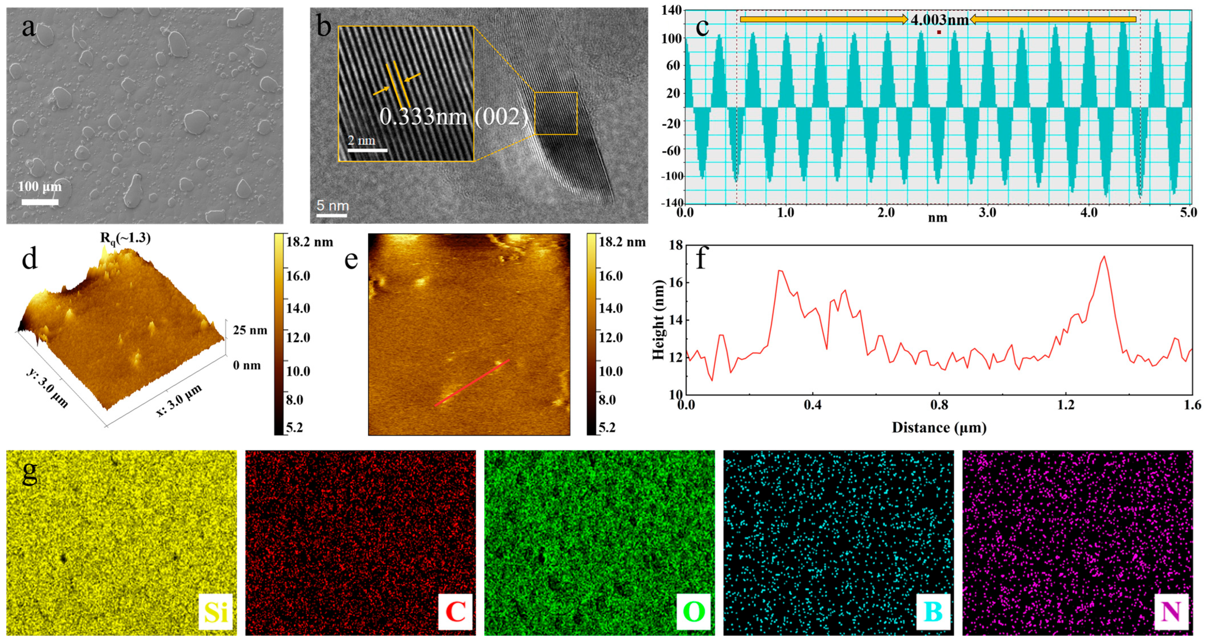
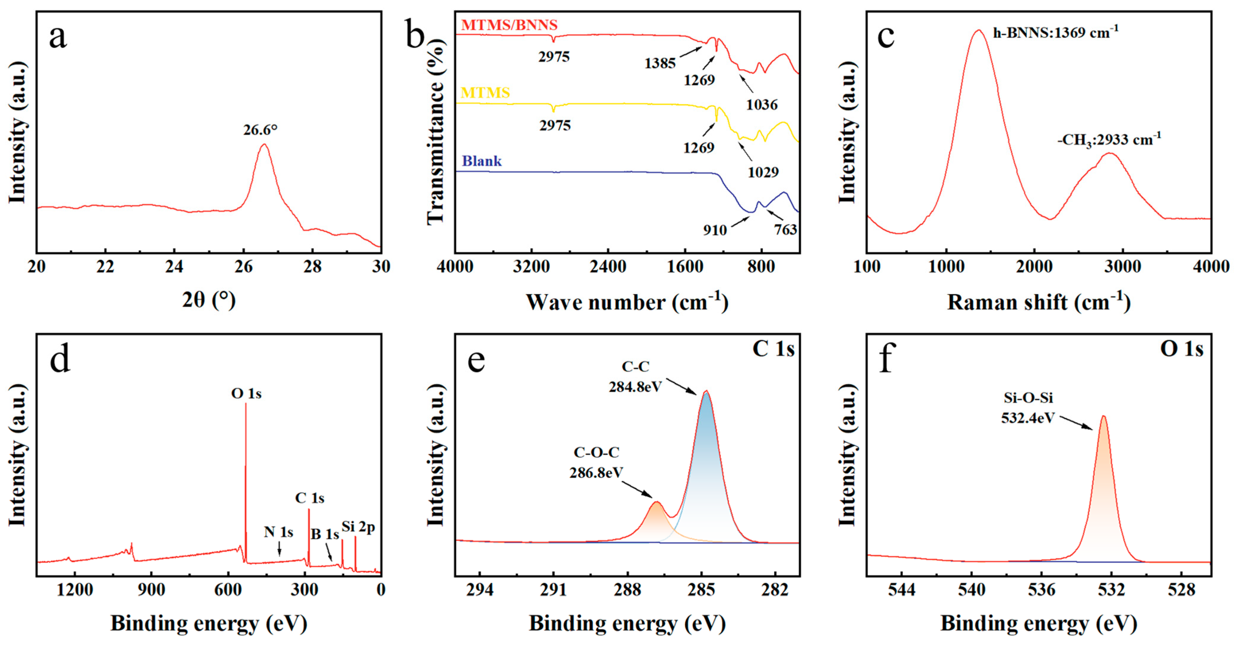
3.2. Surface Morphology and Chemical Composition

The surface morphology of the coating sample was characterized by SEM, as shown in Figure 3a. It can be clearly seen that the two-dimensional sheet-like BNNS is evenly distributed on the coating surface, increasing the roughness of the coating. The rest of the surfaces are intact and crack-free, indicating that the coating is in good condition and has no obvious defects. Figure 3b,c shows the HRTEM image of the coating particles and the lattice spacing image obtained by image analysis, from which it can be calculated that the lattice spacing is 0.333 nm, which corresponds to the lattice fringes of the (002) plane of BNNS. As shown in Figure 3d–f, the surface roughness of the coating was further quantitatively evaluated using AFM. The Rq value of the coating was 1.3 nm, and the roughness was kept at a low level, which can not only ensure a certain hydrophobicity, but also reduce the attachment points and thus reduce the possibility of biological attachment [35]. From the EDS mappings shown in Figure 3g, it can be seen that Si, O, and C elements are widely distributed, which are the main elements constituting MTMS. The content of B and N elements is less than that of the first three elements, but they are evenly distributed. This shows that the coating obtained by spraying is dense and uniform.
To further validate these results, the XRD image shown in Figure 4a shows that there is an obvious peak near 26.6°, which corresponds to the (002) plane of BNNS and is consistent with the results of the HRTEM [36]. In order to understand the surface composition of the material, FTIR, Raman, and XPS tests were performed on the coating samples. As shown in the FTIR results of Figure 4b, the stretching vibration of the C-H and the symmetric bending vibration of Si-C lead to characteristic peaks at 2975 cm−1 and 1269 cm−1, respectively [37,38], and the asymmetric stretching vibration of the Si-O-Si bond generated during the hydrolysis and polycondensation process leads to the characteristic peak at 1036 cm−1 [39]. The peak at 1385 cm−1 is attributed to the in-plane stretching vibration of the B-N bond, while the out-of-plane vibration characteristic peak of the B-N-B bond, which should be around 800 cm−1, may overlap due to the presence of the substrate [40,41]. The peak at 1029 cm−1 in the MTMS can be explained as the low degree of cross-linking of the siloxane network, resulting in a shift of Si-O-Si. In the Raman spectrum, the peaks of BNNS at 1369 cm−1 and the methyl group at 2933 cm−1 are observed (Figure 4c). XPS was further used to determine the chemical bond in the sample. The significant peaks of the sample were C 1s, O 1s and Si 2p (Figure 4d). Due to the low content of BNNS, distinct N 1s and B 1s peaks were not detected (Figure S2a,b). The presence of C-O bonds (286.8 eV) was attributed to the inadequate hydrolysis system (Figure 4e). The presence of a Si-O-Si bond (532.4 eV) further confirmed the success of the hydrolysis and polycondensation reaction of MTMS [42], and was consistent with the results of the FTIR test (Figure 4f and Figure S2c).

3.3. Adhesion Strength and Chemical Stability

According to the ISO2409 standard, after cutting the area with a sharp blade, the tape was quickly pulled back at an angle of 60° to remove the tape. Figure 5a is a schematic diagram of the adhesion test. Figure 5b,c are photos of the coating before and after the tape was peeled off. It can be observed that the surface scratched area is almost intact, and the coating peeling area on the scratched area is less than 5%. The coating adhesion is identified as level 1 (Figure S3a), which meets the requirements of industrial applications. In addition, after peeling, the scratched area still maintains a high contact angle (Figure S3b). For the chemical stability test, the coated glass was immersed in 0.1 M HCl (adjusted to pH 3 and 5), NaCl (concentration of 20‰, pH 7), or 0.1 M NaOH (adjusted to pH 9 and 11) solutions with different pH values. The contact angle of the coating was measured once a day during the immersion period for a total of three days. Figure 5d is a schematic diagram of the chemical stability test. Figure 5e shows the changes in the contact angle of the coating surface at different times under different pH environments. After immersion in a harsh corrosive environment for 72 h, the coating maintained a contact angle of more than 80°. Notably, in a high-salt environment with a pH value of 7, the contact angle of the coating remains above 90°, indicating that the coating can resist dust, acid rain, and salt spray erosion in actual environments.

3.4. Self-Cleaning Performance

Long-term exposure to the complex marine environment will cause offshore photovoltaic systems to be contaminated by various pollutants, which will significantly reduce their light absorption efficiency and thus reduce their power generation performance. Studies have shown that dust accumulation can cause the power generation efficiency of photovoltaic modules to drop by up to 15%–25% [43]. Therefore, photovoltaic modules need to have self-cleaning capabilities to remove the above pollutants.
In the self-cleaning test, the coated glass and blank glass were placed at an angle of 20°, and after sand was evenly sprinkled on them, clean water was dripped on the upper part, and the movement of water droplets and sand was observed. Figure 6 shows the self-cleaning test process of coated glass and blank glass. It can be clearly seen that the water droplets were blocked by sand particles halfway down the blank glass, and only moistened the sand particles without taking them away, leaving residues of pollution adhered to the glass surface. In contrast, on the coated glass, the water droplets slid down very smoothly, easily taking away the sand particles without leaving any residues. Therefore, it has been shown that the coating has excellent self-cleaning ability.

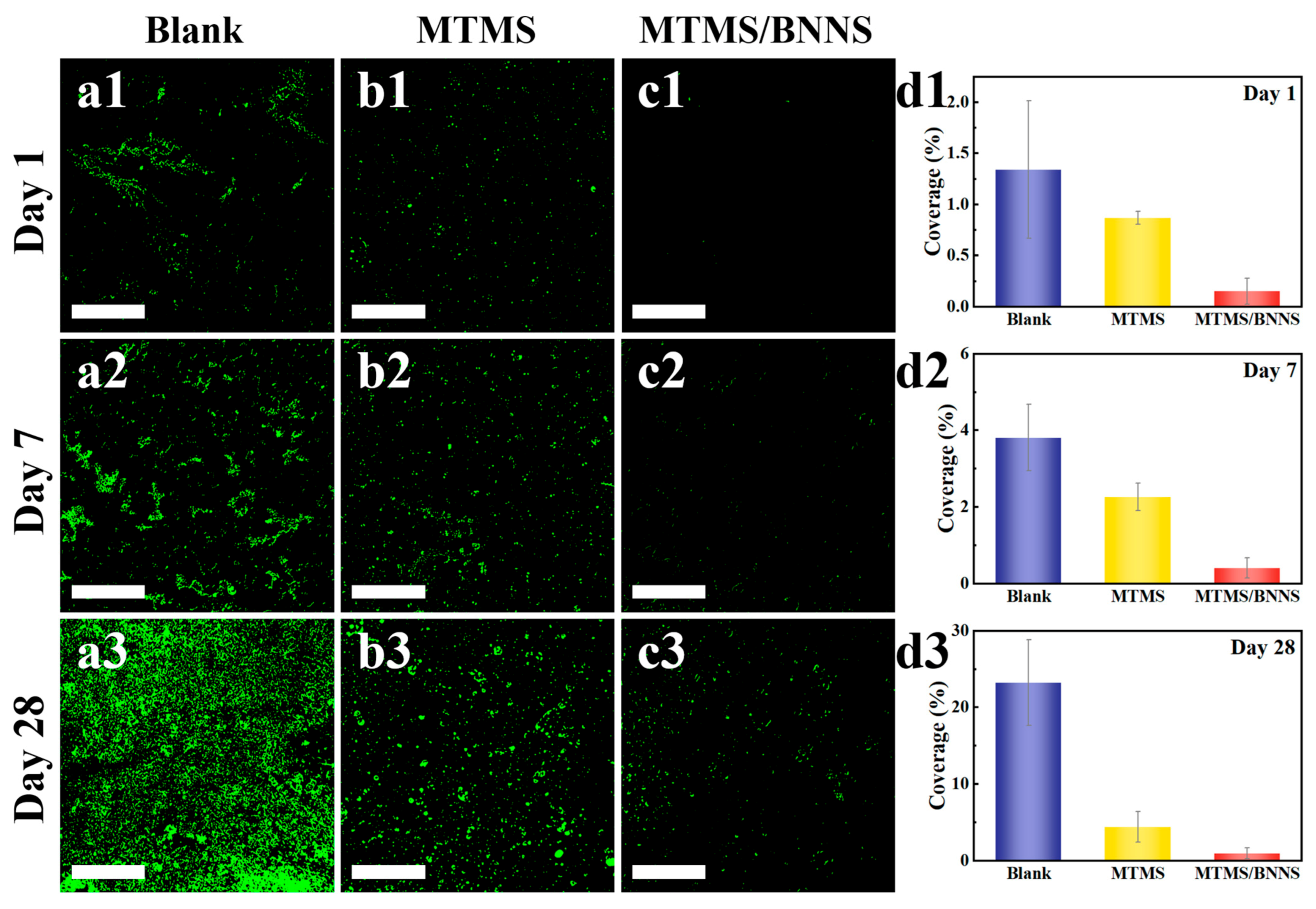
3.5. Biofouling Resistance

In order to evaluate the anti-biofouling performance of the prepared coating, the coating samples were immersed in a medium rich in Chlorella under experimental conditions to observe the growth of algae on the coating surface. Chlorella is a common fouling organism that is widely cultivated in the laboratory. In the experiment, the samples were immersed in the culture medium for 1 day, 7 days, and 28 days. Then, the samples were immersed in glutaraldehyde to fix any algae on the coating surface. The surface was gently washed with artificial seawater and dried in the air, and finally observed and photographed under an optical microscope to characterize the coverage of Chlorella on the coating surface. The coverage results of the Chlorella cells on the sample surfaces are shown in Figure 7a–c, and the corresponding statistical numbers are summarized in Figure 7d. For the blank sample without any surface treatment, the Chlorella cells sporadically covered 1.34% of the surface in just 1 day. After 7 and 31 days of continuous immersion, the coverage of Chlorella cells on the blank sample increased significantly, reaching 3.81% and 23.25%, respectively. Finally, the Chlorella cells formed a denser biofilm, which can be considered as a serious biofouling result. For MTMS, the coverage of Chlorella cells was 0.87%, 2.27%, and 4.43% in 1, 7, and 31 days, respectively. Due to the lower surface energy of the MTMS coating, its anti-biofouling performance was better than that of the blank sample. In Figure 7(b3), a large number of Chlorella cells can be observed on the MTMS surface, which implies the formation of biofouling.
In contrast, after immersion for 1 day, the coverage of Chlorella cells on MTMS/BNNS was only 0.15%, and even after immersion for 28 days, the coverage of Chlorella cells on MTMS/BNNS was only 0.98%. This shows that MTMS/BNNS still maintains excellent anti-biofouling performance after immersion for 28 days. This excellent anti-biofouling performance is attributed to the electrostatic layer on MTMS/BNNS, which is negatively charged and can provide an isolation barrier to prevent the attachment of Chlorella cells.

3.6. Anti-Biofouling Mechanism

During the early stages of marine biofouling, microalgae are among the first organisms to adhere to submerged surfaces. These microalgae can secrete extracellular polymeric substances (EPS), which facilitate their attachment and biofilm formation [44]. Marine microalgae such as Chlorella typically exhibit negatively charged cell surfaces due to the presence of functional groups like carboxyl and hydroxyl on their cell walls. This negative surface charge has been confirmed by zeta potential measurements across various pH conditions. In the pH range from 1.8 to 10.5, the zeta potential of Chlorella vulgaris gradually decreased from −0.2 to −21.8 mV [28]. We conducted a zeta potential test on the stripped coating particles placed in filtered natural seawater. It is important to note that this measurement was performed on a particle suspension after scraping of the cured coating and may not be fully representative of the intact film surface; however, it provides a reasonable approximation of the surface charge behavior for comparative analysis. Zeta potential analysis showed that the coating surface already carried a certain amount of negative potential before the addition of BNNS, with a value of −1.13 mV. Although no obvious Si-OH peaks were detected by FTIR and XPS, possibly due to the high degree of condensation in the MTMS network and the very low abundance of residual silanols, the sol-gel siloxane coating inevitably retained trace amounts of Si-OH sites [45]. Under weak alkaline conditions similar to those in the ocean, these sites can be deprotonated to Si-O [46], which may be the reason for the slight negative potential. After the addition of BNNS, the negative potential further increased to −7.83 mV (Figure 8a). The coating surface has an obvious negative potential, which is the same as the negative charge characteristics that are prevalent on the surface of Chlorella. During the contact between the coating and the algae surface, the electrostatic repulsion of like charges inhibited its initial attachment to the coating (Figure 8b), which reveals one of the reasons for the coating’s ability to resist Chlorella. The negative potential of the coating may be partly due to the deprotonation of Si-OH groups that cannot be completely removed during the hydrolysis and polycondensation of MTMS, but more to the fact that the introduction of BNNS significantly increases the negative surface potential. Electrostatic interactions effectively reduce the probability of biological attachment. In addition, the microstructure and surface properties of the coating further optimize its antifouling performance. By moderately regulating the hydrophobicity and electrostatic repulsion of the coating, a synergistic effect is formed, which effectively prevents the accumulation of Chlorella.

4. Conclusions

In this study, a composite siloxane coating was designed from the perspective of electrostatic repulsion, and the anti-biofouling function of the offshore photovoltaic system was successfully realized. By incorporating boron nitride nanosheets, the negative potential of the coating surface was significantly increased, and the electrostatic repulsion between the coating and the negative charge on the surface of Chlorella effectively prevented adhesion. The prepared coating showed excellent anti-biofouling performance on Chlorella. After immersion with Chlorella for 28 days, the fouling coverage percentage was only 0.98%. In addition, the light transmittance of the coating reached 92.7%, ensuring its application in the field of optical equipment. The coating also showed strong adhesion and reached the level 1 standard. In the chemical stability test, the prepared coating showed certain acid and alkali corrosion resistance, maintained good stability in salt solution, and had good application prospects in the industrialization of marine antifouling. The coating has comprehensive properties such as transparency, self-cleaning, strong adhesion, high chemical stability, and anti-biofouling, and is expected to have application prospects in the field of marine antifouling. In future studies, further evaluation of the mechanical durability of the coating, including hardness and wear resistance under simulated natural conditions, will be considered to better assess its long-term performance in the marine environment.

Supplementary Materials

The following supporting information can be downloaded at: https://www.mdpi.com/article/10.3390/coatings15070769/s1, Figure S1: SEM image of the cross-section of the MTMS/BNNS; Figure S2: (a) XPS spectrum deconvolution for the B1s peak, (b) XPS spectrum deconvolution for the N1s peak. (c) XPS spectrum deconvolution for the Si2p peak.; Figure S3: (a) ISO-2409 standard comparison table [47]. (b) CA of coatings after stripping.

Author Contributions

Conceptualization, L.C. and Q.C.; methodology, Z.D.; software, Z.D.; validation, L.C., Z.D. and Q.C.; resources, Y.G. and Z.H.; data curation, Y.J. and Y.X.; writing—original draft preparation, Z.D.; writing—review and editing, L.C.; supervision, Q.C.; funding acquisition, L.C. All authors have read and agreed to the published version of the manuscript.

Funding

This work was funded by the Central Guidance on Local Science and Technology Development Fund of Zhejiang Province, China (Grant No. 2023ZY1021), and the Major Industry Key Technology Project of Zhoushan, China (Grant No. 2023C03004).

Institutional Review Board Statement

Not applicable.

Informed Consent Statement

Not applicable.

Data Availability Statement

The original contributions presented in this study are included in the article and Supplementary Materials. Further inquiries can be directed to the corresponding author.

Acknowledgments

The authors would like to thank Zhou for helpful discussions on topics related to this work.

Conflicts of Interest

The authors declare no conflicts of interest.

References

  1. Cazzaniga, R.; Rosa-Clot, M. The Booming of Floating PV. Sol. Energy 2021, 219, 3–10. [Google Scholar] [CrossRef]
  2. Kumar, M.; Mohammed Niyaz, H.; Gupta, R. Challenges and Opportunities towards the Development of Floating Photovoltaic Systems. Sol. Energy Mater. Sol. Cells 2021, 233, 111408. [Google Scholar] [CrossRef]
  3. Micheli, L.; Talavera, D.L.; Marco Tina, G.; Almonacid, F.; Fernández, E.F. Techno-Economic Potential and Perspectives of Floating Photovoltaics in Europe. Sol. Energy 2022, 243, 203–214. [Google Scholar] [CrossRef]
  4. Wen, Y.; Lin, P. Offshore Solar Photovoltaic Potential in the Seas around China. Appl. Energy 2024, 376, 124279. [Google Scholar] [CrossRef]
  5. Sahu, A.; Yadav, N.; Sudhakar, K. Floating Photovoltaic Power Plant: A Review. Renew. Sustain. Energy Rev. 2016, 66, 815–824. [Google Scholar] [CrossRef]
  6. Djalab, A.; Djalab, Z.; El Hammoumi, A.; Marco Tina, G.; Motahhir, S.; Laouid, A.A. A Comprehensive Review of Floating Photovoltaic Systems: Tech Advances, Marine Environmental Influences on Offshore PV Systems, and Economic Feasibility Analysis. Sol. Energy 2024, 277, 112711. [Google Scholar] [CrossRef]
  7. Mavraki, N.; Bos, O.G.; Vlaswinkel, B.M.; Roos, P.; de Groot, W.; van der Weide, B.; Bittner, O.; Coolen, J.W.P. Fouling Community Composition on a Pilot Floating Solar-Energy Installation in the Coastal Dutch North Sea. Front. Mar. Sci. 2023, 10, 1223766. [Google Scholar] [CrossRef]
  8. Gu, Y.; Yu, L.; Mou, J.; Wu, D.; Xu, M.; Zhou, P.; Ren, Y. Research Strategies to Develop Environmentally Friendly Marine Antifouling Coatings. Mar. Drugs 2020, 18, 371. [Google Scholar] [CrossRef]
  9. Bian, W.; Li, H.; Xiong, W.; Leung, M.K.H. Photocatalytic Antifouling Coating: From Fundamentals to Applications. Photocatal. Res. Potential 2024, 1, 10008. [Google Scholar] [CrossRef]
  10. Jin, H.; Tian, L.; Bing, W.; Zhao, J.; Ren, L. Bioinspired Marine Antifouling Coatings: Status, Prospects, and Future. Prog. Mater. Sci. 2022, 124, 100889. [Google Scholar] [CrossRef]
  11. Xiang, Z.; Wang, Y.; Ju, P.; Zhang, D. Controlled Synthesis and Photocatalytic Antifouling Properties of BiVO4 with Tunable Morphologies. J. Electron. Mater. 2017, 46, 758–765. [Google Scholar] [CrossRef]
  12. Hu, H.; Chen, M.; Cao, M. TiO2 Antifouling Coating Based on Epoxy-Modified Tung Oil Waterborne Resin. Polym. Polym. Compos. 2021, 29, S521–S529. [Google Scholar] [CrossRef]
  13. Valenzuela, L.; Iglesias, A.; Faraldos, M.; Bahamonde, A.; Rosal, R. Antimicrobial Surfaces with Self-Cleaning Properties Functionalized by Photocatalytic ZnO Electrosprayed Coatings. J. Hazard. Mater. 2019, 369, 665–673. [Google Scholar] [CrossRef] [PubMed]
  14. Latthe, S.S.; Sutar, R.S.; Kodag, V.S.; Bhosale, A.K.; Kumar, A.M.; Kumar Sadasivuni, K.; Xing, R.; Liu, S. Self-Cleaning Superhydrophobic Coatings: Potential Industrial Applications. Prog. Org. Coat. 2019, 128, 52–58. [Google Scholar] [CrossRef]
  15. Latthe, S.S.; Terashima, C.; Nakata, K.; Sakai, M.; Fujishima, A. Development of Sol–Gel Processed Semi-Transparent and Self-Cleaning Superhydrophobic Coatings. J. Mater. Chem. A 2014, 2, 5548–5553. [Google Scholar] [CrossRef]
  16. Zhou, Z.; Ma, B.; Zhang, X.; Tang, L.; Lin, X.; Hu, C.; Ren, K. Enhanced Corrosion Resistance and Self-Cleaning Properties of Superhydrophobic Nickel Coating Fabricated by One-Step Electrodeposition. Ceram. Int. 2023, 49, 13109–13118. [Google Scholar] [CrossRef]
  17. Li, Y.; Wang, G.; Guo, Z.; Wang, P.; Wang, A. Preparation of Microcapsules Coating and the Study of Their Bionic Anti-Fouling Performance. Materials 2020, 13, 1669. [Google Scholar] [CrossRef]
  18. Guan, Y.; Chen, R.; Sun, G.; Liu, Q.; Liu, J.; Yu, J.; Lin, C.; Duan, J.; Wang, J. The Mussel-Inspired Micro-Nano Structure for Antifouling:A Flowering Tree. J. Colloid Interface Sci. 2021, 603, 307–318. [Google Scholar] [CrossRef]
  19. Sun, R.; Zhang, S.; Tong, Z.; Wang, Y.; Gao, F.; Hu, J.; Hou, Y.; Lu, J.; Cong, W.; Sun, Y.; et al. A Bioinspired Antifouling Coating Based on “Host–Guest Interaction” Strategy: Durable Slipperiness and Tunable Transparency. Small 2025, 21, 2409771. [Google Scholar] [CrossRef]
  20. Hu, P.; Xie, Q.; Ma, C.; Zhang, G. Silicone-Based Fouling-Release Coatings for Marine Antifouling. Langmuir 2020, 36, 2170–2183. [Google Scholar] [CrossRef]
  21. Sun, J.; Duan, J.; Liu, X.; Dong, X.; Zhang, Y.; Liu, C.; Hou, B. Environmentally Benign Smart Self-Healing Silicone-Based Coating with Dual Antifouling and Anti-Corrosion Properties. Appl. Mater. Today 2022, 28, 101551. [Google Scholar] [CrossRef]
  22. An, X.; Cheng, J.; Li, Q.; Tang, J.; Li, Z.; Liu, L.; Yang, H.; Wei, C. Development of a Mechanically Robust Silicon-Based Cross-Linking Polymer for the Sustainable Marine Antifouling Coatings. Sustain. Mater. Technol. 2024, 41, e01015. [Google Scholar] [CrossRef]
  23. Lu, G.; Tian, S.; Li, J.; Xu, Y.; Liu, S.; Pu, J. Fabrication of Bio-Based Amphiphilic Hydrogel Coating with Excellent Antifouling and Mechanical Properties. Chem. Eng. J. 2021, 409, 128134. [Google Scholar] [CrossRef]
  24. Yu, R.; Yuan, X. Rising of Boron Nitride: A Review on Boron Nitride Nanosheets Enhanced Anti-Corrosion Coatings. Prog. Org. Coat. 2024, 186, 107990. [Google Scholar] [CrossRef]
  25. Zuo, X.; Chang, K.; Zhao, J.; Xie, Z.; Tang, H.; Li, B.; Chang, Z. Bubble-Template-Assisted Synthesis of Hollow Fullerene-like MoS2 Nanocages as a Lithium Ion Battery Anode Material. J. Mater. Chem. A 2016, 4, 51–58. [Google Scholar] [CrossRef]
  26. Jiang, H.; Cai, Q.; Mateti, S.; Yu, Y.; Zhi, C.; Chen, Y. Boron Nitride Nanosheet Dispersion at High Concentrations. ACS Appl. Mater. Interfaces 2021, 13, 44751–44759. [Google Scholar] [CrossRef]
  27. Hao, W.; Yanpeng, L.; Zhou, S.; Xiangying, R.; Wenjun, Z.; Jun, L. Surface Characteristics of Microalgae and Their Effects on Harvesting Performance by Air Flotation. Int. J. Agric. Biol. Eng. 2017, 10, 125–133. [Google Scholar] [CrossRef]
  28. Li, N.; Wang, P.; Wang, S.; Wang, C.; Zhou, H.; Kapur, S.; Zhang, J.; Song, Y. Electrostatic Charges on Microalgae Surface: Mechanism and Applications. J. Environ. Chem. Eng. 2022, 10, 107516. [Google Scholar] [CrossRef]
  29. ASTM D1141-98(2021); Standard Practice for Preparation of Substitute Ocean Water. ASTM: West Conshohocken, PA, USA, 2021.
  30. ISO 2409:2020; Paints and Varnishes—Cross-Cut Test. ISO: Geneva, Switzerland, 2020.
  31. Zhang, Y.; Wang, T.; Lv, Y. Durable Biomimetic Two-Tier Structured Superhydrophobic Surface with Ultralow Adhesion and Effective Antipollution Property. Langmuir 2023, 39, 2548–2557. [Google Scholar] [CrossRef]
  32. Yue, D.; Jiang, X.; Yu, H.; Sun, D. In-Situ Fabricated Hierarchical Nanostructure on Titanium Alloy as Highly Stable and Durable Super-Lubricated Surface for Anti-Biofouling in Marine Engineering. Chem. Eng. J. 2023, 463, 142389. [Google Scholar] [CrossRef]
  33. Lesniewska, N.; Duval, J.F.L.; Caillet, C.; Razafitianamaharavo, A.; Pinheiro, J.P.; Bihannic, I.; Gley, R.; Cordier, H.L.; Vyas, V.; Pagnout, C.; et al. Physicochemical Surface Properties of Chlorella Vulgaris: A Multiscale Assessment, from Electrokinetic and Proton Uptake Descriptors to Intermolecular Adhesion Forces. Nanoscale 2024, 16, 5149–5163. [Google Scholar] [CrossRef] [PubMed]
  34. Wenzel, R.N. Surface Roughness and Contact Angle. J. Phys. Chem. 1949, 53, 1466–1467. [Google Scholar] [CrossRef]
  35. Lejars, M.; Margaillan, A.; Bressy, C. Fouling Release Coatings: A Nontoxic Alternative to Biocidal Antifouling Coatings. Chem. Rev. 2012, 112, 4347–4390. [Google Scholar] [CrossRef] [PubMed]
  36. Sheng, Y.; Yang, J.; Wang, F.; Liu, L.; Liu, H.; Yan, C.; Guo, Z. Sol-Gel Synthesized Hexagonal Boron Nitride/Titania Nanocomposites with Enhanced Photocatalytic Activity. Appl. Surf. Sci. 2019, 465, 154–163. [Google Scholar] [CrossRef]
  37. Xu, L.; Liu, Y.; Yuan, X.; Wan, J.; Wang, L.; Pan, H.; Shen, Y. One-Pot Preparation of Robust, Ultraviolet-Proof Superhydrophobic Cotton Fabrics for Self-Cleaning and Oil/Water Separation. Cellulose 2020, 27, 9005–9026. [Google Scholar] [CrossRef]
  38. Siuda, J.; Perdoch, W.; Mazela, B.; Zborowska, M. Catalyzed Reaction of Cellulose and Lignin with Methyltrimethoxysilane—FT-IR, 13C NMR and 29Si NMR Studies. Materials 2019, 12, 2006. [Google Scholar] [CrossRef]
  39. Sato, Y.; Hayami, R.; Gunji, T. Characterization of NMR, IR, and Raman Spectra for Siloxanes and Silsesquioxanes: A Mini Review. J. Sol-Gel Sci. Technol. 2022, 104, 36–52. [Google Scholar] [CrossRef]
  40. Song, J.; Dai, Z.; Li, J.; Tong, X.; Zhao, H. Polydopamine-Decorated Boron Nitride as Nano-Reinforcing Fillers for Epoxy Resin with Enhanced Thermomechanical and Tribological Properties. Mater. Res. Express 2018, 5, 075029. [Google Scholar] [CrossRef]
  41. Chaturbedy, P.; Ahamed, M.; Eswaramoorthy, M. Oxidative Dehydrogenation of Propane over a High Surface Area Boron Nitride Catalyst: Exceptional Selectivity for Olefins at High Conversion. ACS Omega 2018, 3, 369–374. [Google Scholar] [CrossRef]
  42. Ma, J.W.; Lee, W.J.; Bae, J.M.; Jeong, K.S.; Oh, S.H.; Kim, J.H.; Kim, S.-H.; Seo, J.-H.; Ahn, J.-P.; Kim, H.; et al. Carrier Mobility Enhancement of Tensile Strained Si and SiGe Nanowires via Surface Defect Engineering. Nano Lett. 2015, 15, 7204–7210. [Google Scholar] [CrossRef]
  43. Rashid, M.; Yousif, M.; Rashid, Z.; Muhammad, A.; Altaf, M.; Mustafa, A. Effect of Dust Accumulation on the Performance of Photovoltaic Modules for Different Climate Regions. Heliyon 2023, 9, e23069. [Google Scholar] [CrossRef]
  44. Li, Y.; Ning, C. Latest Research Progress of Marine Microbiological Corrosion and Bio-Fouling, and New Approaches of Marine Anti-Corrosion and Anti-Fouling. Bioact. Mater. 2019, 4, 189–195. [Google Scholar] [CrossRef] [PubMed]
  45. Katagiri, K.; Hashizume, M.; Ariga, K.; Terashima, T.; Kikuchi, J. Preparation and Characterization of a Novel Organic–Inorganic Nanohybrid “Cerasome” Formed with a Liposomal Membrane and Silicate Surface. Chem.—Eur. J. 2007, 13, 5272–5281. [Google Scholar] [CrossRef] [PubMed]
  46. Pavan, C.; Sydor, M.J.; Bellomo, C.; Leinardi, R.; Cananà, S.; Kendall, R.L.; Rebba, E.; Corno, M.; Ugliengo, P.; Mino, L.; et al. Molecular Recognition between Membrane Epitopes and Nearly Free Surface Silanols Explains Silica Membranolytic Activity. Colloids Surf. B Biointerfaces 2022, 217, 112625. [Google Scholar] [CrossRef] [PubMed]
  47. Zhou, J.; Su, J.; Su, F.; Zhao, T.; Li, J.; Yang, P.; Zhang, Q. Synthesis of Robust Superhydrophobic EP/F-CNTs/SiO2 Composite Coating with Excellent Anti-Corrosion and Wear-Resistant Property. J. Coat. Technol. Res. 2025. [Google Scholar] [CrossRef]
Figure 1. Schematic illustration of the coating preparation process.
Coatings 15 00769 g001
Figure 2. SEM images and corresponding water contact angles of MTMS/BNNS coatings with different BNNS contents: (a) 0.1 wt %, (b) 0.3 wt %, (c) 0.5 wt %, (d) 0.7 wt %, and (e) 1 wt %; (f) optical transparency of the coatings as a function of BNNS content.
Coatings 15 00769 g002
Figure 3. (a) SEM image, (b) HRTEM, (c) lattice spacing image, (d) 3D AFM morphology, (e) 2D AFM morphology, (f) height profile across the red line in (e), (g) EDS mapping; the scale is the same as (a).
Coatings 15 00769 g003
Figure 4. (a) XRD pattern, (b) FTIR spectra, (c) Raman shift spectra, (d) XPS spectra, (e) XPS spectrum deconvolution for the C1s peak, (f) XPS spectrum deconvolution for the O1s peak.
Coatings 15 00769 g004
Figure 5. (a) Schematic diagram of the adhesion test. Photographs of the coating before (b) and after (c) tape peeling. (d) Schematic diagram of the chemical stability test. (e) Changes in CA after soaking in different pH solutions for different time periods.
Coatings 15 00769 g005
Figure 6. Pollutant-repellency behavior on (a1a3) a blank surface and (b1b3) a coated surface with sand.
Coatings 15 00769 g006
Figure 7. ImageJ-processed images of the Chlorella covering on the (a1a3) blank, (b1b3) MTMS, and (c1c3) MTMS/BNNS after being immersed in a suspension of Chlorella for 1, 7, and 28 days, respectively. Statistical results of the Chlorella coverage on blank, MTMS, and MTMS/BBNS after being immersed in a suspension of Chlorella for (d1) 1, (d2) 7, and (d3) 28 days, respectively. All the scale bars are 100 μm.
Coatings 15 00769 g007
Figure 8. (a) Zeta potential without and with BNNS incorporated. (b) Schematic illustration of the antifouling mechanism of the coating.
Coatings 15 00769 g008
Disclaimer/Publisher’s Note: The statements, opinions and data contained in all publications are solely those of the individual author(s) and contributor(s) and not of MDPI and/or the editor(s). MDPI and/or the editor(s) disclaim responsibility for any injury to people or property resulting from any ideas, methods, instructions or products referred to in the content.

