Abstract
When nitriding 38CrMoAl steel, there are areas that need to be protected, as the process may interfere with subsequent steps. The large-scale demand for anti-nitriding coatings has driven the investigation and development of more effective anti-nitriding coatings. In this study, various anti-nitriding coating formulations were applied to the surface of 38CrMoAl steel samples via brushing. Following the nitriding treatment, SEM, EDS, and hardness tests were performed to systematically investigate the effects of the considered formulations on the mechanical and microstructural properties of the 38CrMoAl steel. The experimental results indicated that the hardness values for all the samples remained below 600 HV, demonstrating that coatings composed of tin powder, lead powder, and various oxides possess anti-nitriding abilities, to a certain degree. The lead powder formulation exhibited the best anti-nitriding performance, achieving an average surface hardness of 273.48 HV. No nitriding layer was observed in the cross-section, and no nitrogen (N) was detected on either the surface or in the cross-section. In comparison, the samples coated with tin/lead and tin/lead/alumina formulas demonstrated relatively lower anti-nitriding capabilities, with an average surface hardness below 320 HV, satisfying the hardness requirements for anti-nitriding coatings while preventing the formation of a nitriding layer.
1. Introduction
Nitriding is a chemical heat treatment process in which nitrogen atoms are diffused into the surface layer of a workpiece at a certain temperature through a specific method. Common nitriding methods include liquid nitriding, gas nitriding, and ion nitriding. Nitriding is a widely adopted thermochemical surface treatment process that effectively enhances the surface hardness, wear resistance, fatigue strength, and corrosion resistance of workpieces [,,]. Therefore, nitriding treatment is frequently carried out in mechanical manufacturing. 38CrMoAl steel is a medium-carbon alloy steel that is commonly utilized in the production of nitrided components [,] that have high fatigue strength, excellent wear resistance, and high tensile strength. These components include cylinder liners, seat sleeves, covers, piston bolts, lathe spindles, and screws []. Due to the extremely high hardness of the parts after nitriding, the interface between threaded sections and other components may generate a cutting effect at the connection point. This phenomenon can adversely affect the reliability of the connection and the stress distribution, potentially leading to failure of the part. Consequently, localized anti-nitriding treatment for nitrided parts is highly recommended to mitigate these issues.
To date, the majority of research studies in both domestic and international contexts have primarily focused on optimizing nitriding treatment processes and minimizing failures associated with nitriding. Wang Tiancheng et al. [] conducted a nitriding and laser quenching treatment on 38CrMoAl steel and studied the microstructure and properties of the composite modified layer. The thickness of the composite modified layer increased, and there was a stable friction coefficient. Dongjing Liu et al. [] systematically investigated the effects of rare earth elements on the properties of the nitrided layer; they were found to enhance the layer’s corrosion resistance, increase its thickness, and improve the surface hardness. Matthias et al. [] optimized the preheating treatment process to form finer precipitates prior to nitriding, thereby enhancing the performance and achieving a higher hardness in the nitrided components. Fuyao Yan et al. [] investigated the impact of decarburization on the microstructure and growth kinetics of the nitriding layer that formed on the decarburized surface. Lisha Fan et al. [] systematically investigated the effects of laser power on the surface properties of nitrided samples. The laser excitation of ammonia was found to effectively improve the utilization rate of ammonia and enhance the efficiency of nitriding. Huanhuan Hong et al. [] proposed an efficient approach to accelerate ion nitriding, demonstrating significant improvements in both surface friction behavior and mechanical properties. Feng Zhiguo et al. [] investigated the effects of nitriding pressure on the microstructure and properties of the nitrided layer. O’Sullivan B. J. et al. [] compared several nitriding methods and processes and found a more effective nitriding method. Zhou Lang et al. [] investigated the effects of different ammonia and water concentrations on the performance of the nitrided layer. Ma W.P. Tong et al. [] systematically investigated the effects of surface nanocrystalline layers on the low-temperature gas nitriding process. Their findings demonstrated that, in comparison with conventional nitriding, this novel gas nitriding technology significantly improved the hardness and wear resistance of the nitrided layer. Zhihao Feng et al. [] conducted a systematic investigation into the effects of laser treatment on nitriding processes. Their analysis demonstrated that laser-assisted nitriding not only effectively refined the surface grains and facilitated the formation of hard nitrides but also significantly enhanced the hardness and wear resistance of the alloy. Xingde Zhao et al. [] analyzed the causes of the abnormal bright white layer that forms during nitriding and proposed corresponding optimization strategies. Włoczewski et al. [] systematically investigated the mechanical and physical properties of high-entropy alloys after a nitriding treatment. Their findings demonstrated that high-entropy nitrides not only significantly improved the hardness but also effectively reduced the coefficient of friction. There is relatively little research on anti-nitriding coatings and anti-nitriding mechanisms. Only some principles have been mentioned in studies on nitriding failure. Zheng Hongfu [] proposed that the surface of stainless-steel workpieces often forms a passivation film that is primarily composed of chromium oxide. This film prevents oxygen atoms from further reacting with iron and also inhibits nitrogen atoms from combining with iron. Tang Shunqi’s [] research indicated that the dense oxide film formed on workpiece surfaces can impede the infiltration of nitrogen atoms.
Anti-nitrogen-infiltration coatings mainly function by forming a protective layer on the metal surface to prevent nitrogen atoms from penetrating. However, commercially available anti-nitrogen-infiltration reagents tend to lose their efficacy over time after being opened, which limits their practical application in production. Therefore, in production processes, it is preferable to prepare the anti-nitrogen-infiltration coating in-house. By mixing tin powder and shellac solution in a 7:3 ratio and applying it evenly onto the surface of the workpiece intended for anti-nitrogen infiltration, excellent anti-nitrogen infiltration performance can be achieved while ensuring convenient preparation. Nevertheless, the self-prepared anti-nitrogen diffusion coating is formulated with a single component. Tin, which is a critical base material, is costly and its reserves are decreasing annually. At present, the content of tin in the Earth’s crust is only 0.004%, making it an important strategic mineral. Its application in anti-nitrogen-infiltration coatings is challenging, and its full value is difficult to realize. Based on the existing anti-nitrogen-infiltration coating formula being utilized, this study systematically conducted anti-nitriding experiments and investigated the underlying mechanisms. We designed and optimized novel anti-nitriding coating formulas by reducing the proportion of tin powder and identifying alternative effective anti-nitriding components. This approach led to the development of new low-tin and non-tin anti-nitriding coatings, which possess significant application value, economic benefits, and important practical implications.
2. Materials and Methods
2.1. Experimental Materials
The test material consisted of 38CrMoAl steel, which was subjected to heat treatment involving quenching at 940 °C for 1 h (oil cooling), followed by tempering at 650 °C for 30 min (oil cooling). The specimen dimensions were Φ30 mm × 15 mm, and the chemical composition is presented in Table 1. After being ground using a metallographic grinding machine, the sample exhibited a mirror-like surface, as illustrated in Figure 1.

Table 1.
Chemical composition of the 38CrMoAl steel (mass fraction, %).
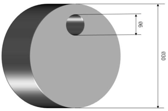
Figure 1.
Sample for nitrogenization.
2.2. Preparation of Anti-Seepage Nitrogen Coating
Lead and tin, as group IV elements in the periodic table, exhibit similar chemical and physical properties. Based on this similarity, the tin powder in the coating formulation was partially substituted with lead powder to obtain coatings with similar nitrogen infiltration resistance. Previous studies have indicated that an oxide film can effectively inhibit the interaction between nitrogen and iron atoms. In this experiment, lead powder and various oxides were incorporated into the coating formulation to enhance its nitrogen-inhibiting performance. Shellac films are easily soluble in simple-alcohol solvents such as ethanol and exhibit viscosity in dilute solutions. After coating, they dry quickly and form a smooth film with strong adhesion to the metal surface. Therefore, shellac films were selected as the curing adhesive. The specific composition ratios of the anti-nitrogen coatings are given in Table 2.
Table 2.
Anti-nitriding coating formulas.
2.3. Test Method
Six types of anti-nitriding coatings were mixed in the predetermined proportions and subsequently applied to the samples. Following the application, the samples were allowed to stand until the anti-permeation nitrogen coating was completely dried. Once dried, the samples were transferred to a nitriding furnace to undergo the nitriding process. This experiment employed a two-stage gas nitriding technique. Under high-temperature conditions, ammonia is decomposed into active nitrogen atoms and hydrogen atoms. Through the precise control of the temperature and ammonia decomposition rate, this technique exhibits substantial advantages in achieving the accurate regulation of the nitrided layer thickness and uniform performance characteristics. In the first stage, the nitriding temperature was maintained at 510 ± 5 °C with an ammonia decomposition rate of 18%–25% over 48 h. This stage facilitated the formation of highly dispersed nitride particles on the surface of the parts, thereby establishing a higher nitrogen concentration. Subsequently, the temperature was gradually increased to initiate the second stage. During the second stage, the nitriding temperature was set between 540 and 560 °C with an ammonia decomposition rate of 45%–65% for 18–20 h. This stage involved increasing both the nitriding temperature and ammonia decomposition rate to enhance the inward diffusion rate of nitrogen atoms from the surface.
The specimen images and the testing process are shown in Figure 2. Upon the completion of the nitriding process, the anti-nitriding coating on the sample surface must be removed prior to conducting the relevant tests. For this purpose, an MP-2 type metallographic grinding and polishing machine(Sanfeng Precision Measuring Instruments Co., Ltd., Guangzhou, China) was employed, operating at a low speed of 400 r/min. Abrasive papers with 800, 1000, and 1200 mesh were sequentially used (i.e., progressively finer particles). Water cooling was applied during grinding and polishing to safeguard the integrity of the nitrided layer and to protect other sensitive microstructures from potential damage.
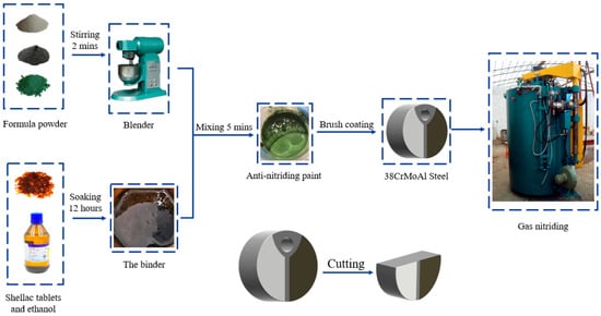
Figure 2.
Experimental flowchart.
According to the stipulations in “JB/T9199-2008 Anti-seepage Coating Technical Requirements”, the maximum hardness (Hmax) of the surface of a workpiece coated with an anti-seepage nitriding coating should not exceed 320 HV0.2 to be considered acceptable. After nitriding, the sample end face was ground using a metallographic grinding and polishing machine(Sanfeng Precision Measuring Instruments Co., Ltd., Guangzhou, China). The hardness distribution and gradient of the end face were measured using an HV-5z Vickers microhardness tester(Guangxi Huided Trading Co., Ltd., Beihai, China). The tester employs a regular tetrahedral diamond indenter with a relative surface angle of 136°, a loading force of 5 kgf, and a holding time of 10 s. After the rhombic indentation is pressed out, the Vickers hardness value was calculated using Formula (1), which is expressed in HV units.
The samples were cut in half using a wire electrical discharge machining (WEDM) system. Subsequently, the end faces and cross-sections were ground with 1200-grit sandpaper, polished to achieve a mirror-like finish, and etched with a 4 vol% nitric acid alcohol solution. The microstructure of the sample surfaces was examined using an optical microscope (PH-M 3230BD, Phoenix Optical Group Co., Ltd., Shangrao, China). The morphology of the oxide layer was characterized by scanning electron microscopy (SEM; ZEISS Sigma 500, Carl Zeiss Optical Co., Ltd., Guangzhou, China), while energy-dispersive X-ray spectroscopy (EDS; Oxford X-Max 80, Oxford Instruments Technology Co., Ltd., Shanghai, China) was employed to analyze the elemental composition of the anti-nitriding coating and the depth of nitrogen infiltration. Finally, the phase composition of the surface after removing the coating was determined using X-ray diffraction (XRD, XPert3Powder, PANalytical B.V., Almelo, the Netherlands) with Cu Kα radiation over a 2θ range of 10–90° at a scanning rate of 5°/min.
3. Results
3.1. Microstructure
After gas nitriding, the surface of typical 38CrMoAl steel forms a compound layer that appears bright white under a metallographic microscope, which is commonly referred to as the bright white layer. This layer primarily consists of the ε phase. The second layer consists of the γ′ phase dispersed in the matrix, which appears black under a metallographic microscope. The distinct boundary with the central pearlite structure corresponds to the γ′ + α structure []. The original state of 38CrMoAl steel is normalizing + tempering, with an austenitization temperature of 930 °C, indicating that it can transform into an austenite structure at high temperatures. When 38CrMoAl steel is not subjected to gas nitriding, its microstructure consists of tempered pearlite []. Before gas nitriding, 38CrMoAl steel must undergo quenching and high-temperature tempering treatment to achieve a uniform, fine, tempered pearlite structure, thereby providing an optimal microstructural foundation for subsequent gas nitriding. The phase transformation process of 38CrMoAl steel after gas nitriding is primarily influenced by two factors: thermodynamics and kinetics [].
After the specimens were coated with a nitrogen-resistant coating on their surfaces, they underwent nitriding treatment. Upon completion of the nitriding process, the surfaces were polished and corroded, and the surface morphology was observed, as shown in Figure 3. The nitrided microstructures of the specimens coated with tin powder, tin/lead powder, and tin/lead/alumina powder are shown in Figure 3a, Figure 3c and Figure 3f, respectively. The surfaces of these specimens were uniformly covered with fine granular substances, and faint grain boundaries were observable. The sample coated with lead powder (Figure 3b) exhibited distinct and irregular grain boundaries over a relatively large area on its surface. This phenomenon may be attributed to the holding time during nitriding, which likely promoted grain growth []. The nitrided specimens coated with tin/lead/chromium oxide and tin/lead/copper oxide exhibited irregular grain boundaries on the surface, but the extent of the grain boundary range was significantly smaller compared to that shown in Figure 3b. The variation in grain boundary color was attributed to the different nitriding products. Grain boundaries containing undissolved carbides exhibit a lighter color, whereas Cr-rich grain boundaries form a Cr2O3 film, resulting in a darker appearance.
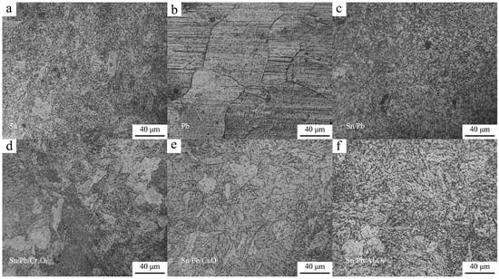
Figure 3.
Metallographic pictures of the specimen end faces. (a) Surface of the sample coated with coating formula 1; (b) Surface of the sample coated with coating formula 2; (c) Surface of the sample coated with coating formula 3; (d) Surface of the sample coated with coating formula 4; (e) Surface of the sample coated with coating formula 5; (f) Surface of the control group sample.
After radially sectioning the samples, their cross-sectional microstructure was examined. The boundary microstructures of the samples are presented in Figure 4. It was observed that no distinct bright white nitrided layer formed at the sample boundary, indicating that the anti-nitriding coating, to some extent, inhibited the formation of the bright white nitrided layer and exerted a certain restraining effect on the infiltration of N. As can be observed from Figure 4d,e, black nitride particles were distributed within the grain boundary microstructure, indicating that a diffusion layer had successfully formed despite the absence of a bright white nitrided layer. Consequently, the hardness of these two samples remained relatively high.
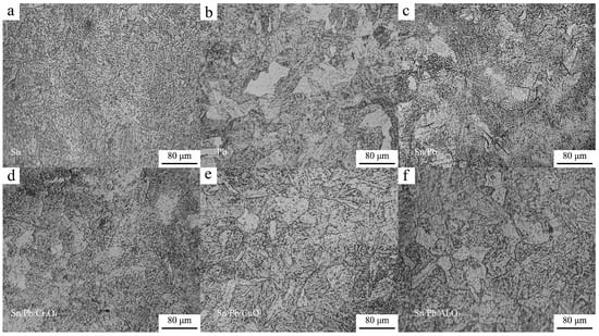
Figure 4.
Metallographic structure of the specimen cross-sections. (a) The cross-section of the sample coated with Formula 1; (b) The cross-section of the sample coated with Formula 2; (c) The cross-section of the sample coated with Formula 3; (d) The cross-section of the sample coated with Formula 4; (e) The cross-section of the sample coated with Formula 5; (f) The cross-section of the sample coated with Formula 6.
3.2. Hardness Analysis
Three to four measurement points were selected in the upper, middle, and lower regions of the sample surface coated with the specified formula to determine the hardness values. The obtained hardness data are presented in Figure 5. The uniformity of the coating’s anti-nitriding performance was assessed based on the variation in hardness values across different regions. Formula 1 is a commonly used formulation in industrial applications and served as a benchmark for comparison. After nitriding, the hardness of the 38CrMoAl steel coated with Formulas 1–3 ranged from 314 to 378 HV, 228 to 340 HV, and 272 to 298 HV, respectively. These results suggest that lead powder has a superior anti-nitriding effect compared to tin powder. The hardness of the 38CrMoAl steel coated with Formula 4 was marginally higher compared to the previous formulations, with values ranging from 481 HV to 600 HV. For Formula 5, the hardness decreased slightly and fluctuated within the range of 436–558 HV. Among the several oxide-containing coating formulations, the anti-nitriding performance of Formula 6 was found to be the highest: the hardness values of the samples ranged from 263 HV to 376 HV, closely resembling those of the samples coated with Formula 1. Table 3 shows the average hardness values obtained from the measurements. 38CrMoAl steel is typically subjected to quenching and tempering treatment to achieve a uniform microstructure and excellent comprehensive mechanical properties. As a result, its hardness is generally controlled within the range of 220–320 HV. After nitriding, its hardness typically increases to above 920 HV [,]. From the hardness results, it was evident that anti-nitriding coatings composed of tin powder, lead powder, and various oxides effectively suppressed the increase in hardness and demonstrated a certain degree of nitriding prevention capability. However, only Formulas 2, 3, and 6 were deemed suitable for anti-nitriding operations, as their sample hardness values closely resembled those prior to nitriding. Based on the metallographic analysis presented earlier, the surfaces of Formulas 3 and 6 were similar to those of Formula 1, indicating similarities in their surface microstructures. Furthermore, the hardness values of Formulas 2, 3, and 6 were all lower than that of Formula 1, suggesting that these three formulas exhibit superior performance and are more suitable for anti-nitriding applications. Compared with Formula 1, the formulations containing chromium oxide and copper oxide resulted in inferior hardness values. Although these formulations had a certain anti-nitriding effect, their relatively high hardness renders them unsuitable for practical production processes.
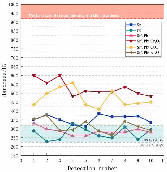
Figure 5.
Hardness of samples after nitriding treatment.
Table 3.
Average hardness of 38CrMoAl steel samples after nitriding.
3.3. Energy Spectrum Analysis
The end face of the samples was subjected to EDS surface scanning to analyze its chemical composition and element distribution. Specific elements were selected for scanning based on the different formulations to determine whether the formulations’ components had infiltrated the sample surface as a measure of their anti-nitriding performance. Figure 6 presents the SEM image and EDS results of the surface of the 38CrMoAl steel coated with Formula 1 after nitriding. From the figure, it can be observed that a distinct alloy nitride boundary structure formed; this was due to elements with a high affinity for nitrogen tending to segregate at grain boundaries, leading to the formation of alloy nitrides []. By integrating Figure 6b,c, the primary surface component of the sample after nitriding was identified as α-Fe, with a trace amount of N uniformly dispersed across the surface. Although the mapping image in Figure 6(c3) indicates the presence of Sn on the sample surface, the EDS analysis did not detect any Sn components (Figure 6b). Consequently, the patterns observed in the mapping image were interpreted as interference noise based on the quantification standard provided by the EDS content table. In subsequent samples with conflicting information from the mapping images and the EDS content table, the EDS content table data were given precedence. No coating elements were detected on the surface of the 38CrMoAl steel treated with Formula 1, suggesting that the anti-seepage mechanism of this coating does not rely on element substitution [], but rather on the formation of a protective film on the surface to achieve the desired anti-seepage performance. The SEM images and EDS results of the surface of the 38CrMoAl steel coated with Formula 2 after nitriding are presented in Figure 7. In Figure 7a, a clear grain boundary structure is evident, characterized by relatively large grain boundary regions. Additionally, coarse vein-like structures can be observed, which were formed during the nitriding process. By integrating Figure 7b,(c1), it was confirmed that the sample was primarily composed of Fe, with no Pb detected. This indicates that this coating formula achieved anti-nitriding effects by forming a thin film on the surface. Trace amounts of N were distributed discretely in a point-like pattern on the sample surface, suggesting the formation of specific alloy nitrides during the nitriding process. The SEM images and EDS results for the 38CrMoAl steel coated with Formula 3 after the nitriding treatment are presented in Figure 8. In the SEM image (Figure 8a), some granular undissolved nitrides [] can be observed, which accounted for the relatively high N content on the surface. Formula 3 is a combination of the components from Formulas 1 and 2, and thus its elemental detection results were similar. Neither Sn nor Pb was detected on the surface.
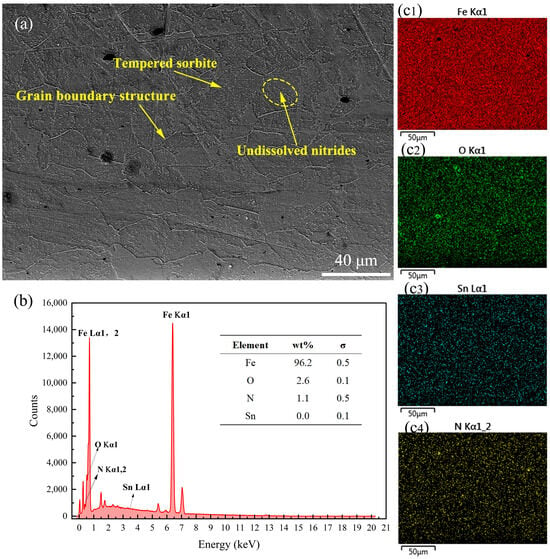
Figure 6.
Surface energy spectrum analysis results for the specimen coated with Formula 1. (a) SEM image of the surface; (b) energy spectrum and elemental composition table; (c1–c4) surface scanning mapping images for Fe, O, Sn, and N.
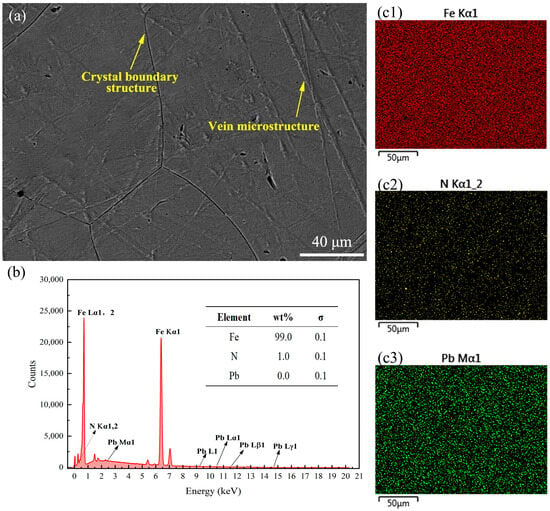
Figure 7.
Surface energy spectrum analysis results for the specimen coated with Formula 2. (a) SEM image of the surface; (b) energy spectrum and elemental composition table; (c1–c3) surface scanning mapping images for Fe, N, and Pb.
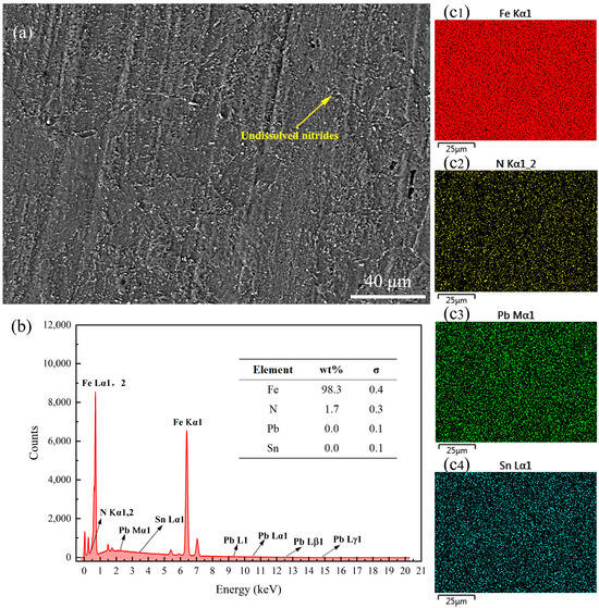
Figure 8.
Surface energy spectrum analysis results for the specimen coated with Formula 3. (a) SEM image of the surface; (b) energy spectrum and elemental composition table; (c1–c4) surface scanning mapping images for Fe, N, Pb, and Sn.
Figure 9 presents the SEM images and energy spectrum analysis results of the surface of the 38CrMoAl steel treated with Formula 4 after nitriding. This sample exhibited the highest hardness among all samples; however, no N was detected on the surface. As shown in the SEM image in Figure 9a, alloy nitride structures and granular undissolved nitrides were observed on the surface. A detailed energy spectrum scanning analysis of its cross-section was conducted, which will be discussed in the subsequent sections to further clarify these results. Figure 10 presents the SEM image and energy spectrum analysis results of the surface of the 38CrMoAl steel treated with Formula 5 after nitriding. A small amount of N was found to be uniformly dispersed on the sample surface, leading to the formation of alloy nitrides. Meanwhile, trace amounts of Cu and Pb were detected on the sample surface, suggesting that some components infiltrated into the sample surface. Figure 11 presents the SEM image and energy spectrum analysis results of the surface of the 38CrMoAl steel coated with Formula 6 after the nitriding treatment. As shown in the figure, undissolved nitride particles were mostly absent on the surface, which was predominantly composed of the sample matrix. Moreover, no N was detected on the surface of this coating. In conjunction with Figure 5, the surface hardness of this formula was found to be comparable to the matrix hardness, suggesting that this formula effectively prevented nitriding.
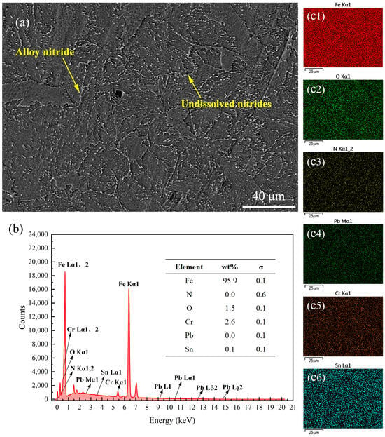
Figure 9.
Surface energy spectrum analysis results for the specimen coated with Formula 4. (a) SEM image of the surface; (b) energy spectrum and elemental composition table; (c1–c6) surface scanning mapping images for Fe, O, N, Pb, Cr, and Sn.
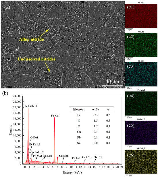
Figure 10.
Surface energy spectrum analysis results for the specimen coated with Formula 5. (a) SEM image of the surface; (b) energy spectrum and elemental composition table; (c1–c6) surface scanning mapping images for Fe, O, Sn, Pb, Cu, and N.
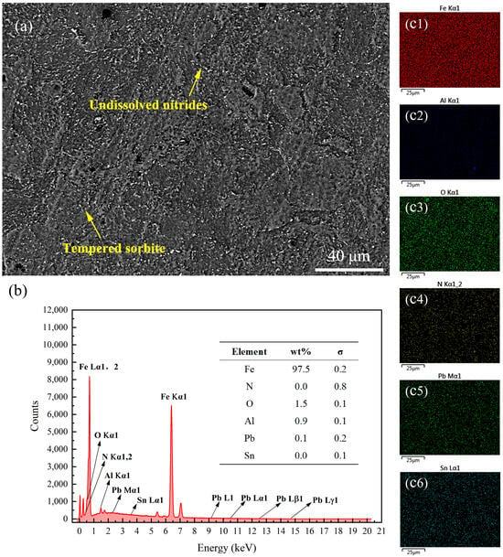
Figure 11.
Surface energy spectrum analysis results for the specimen coated with Formula 6. (a) SEM image of the surface; (b) energy spectrum and elemental composition table; (c1–c6) surface scanning mapping images for Fe, Al, O, N, Pb, and Sn.
XRD analysis was also performed on the surfaces of the six samples, and the results are presented in Figure 12. The diffraction patterns of all the samples primarily consist of the main peaks corresponding to α-Fe and secondary peaks attributed to Fe-Cr alloys. The diffraction peaks of the samples did not match those of Fe3N, confirming the absence of Fe3N formation in the samples. However, the main diffraction peaks of the samples coated with Formulas 4 and 5 exhibited a slight shift toward lower angles. This suggests that after the nitriding treatment, nitrogen atoms may have existed in the matrix as a supersaturated solid solution (e.g., α-Fe(N)), without forming distinct nitride phases.
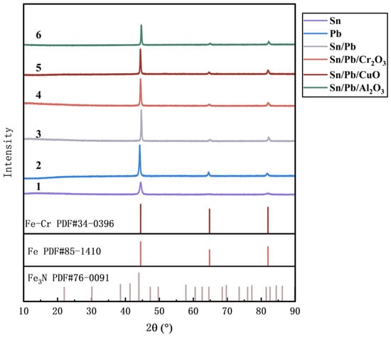
Figure 12.
XRD patterns of surfaces of the different samples.
Figure 13, Figure 14, Figure 15, Figure 16, Figure 17 and Figure 18 present the energy spectrum diagrams of the cross-sections of the 38CrMoAl steel samples coated with Formulas 1–6, respectively, at different depths. The nitrogen content for all the formulations is presented in Table 4. As shown in Figure 13 and Figure 15, although trace amounts of N were detected on the surface of the 38CrMoAl steel samples treated with coating Formulas 1 and 3, no N was detected below the surface. This indicates that alloy nitrides only formed on the surface–, and the N did not penetrate into the interior of the sample. This was due to the higher nitrogen concentration on the sample surface during nitriding, which facilitated nitride formation []. Figure 14 shows that trace amounts of N were detected near the surface of the sample, while no N was found below a depth of 100 μm. A small amount of alloy nitrides formed at the surface and near-surface regions, which also hindered the inward diffusion of the remaining N [].
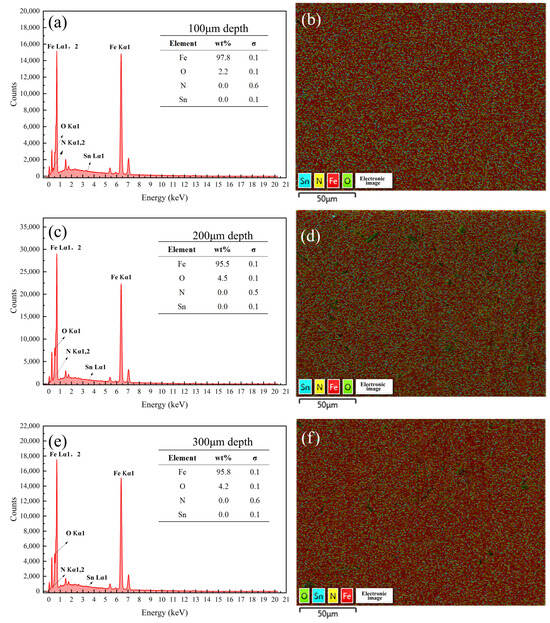
Figure 13.
Energy spectrum analysis results of the samples coated with Formula 1 at different depths. Energy spectrum and elemental composition table for depths of (a) 100 μm, (c) 200 μm, and (e) 300 μm; mapping fusion image for depths of (b) 100 μm, (d) 200 μm, and (f) 300 μm.
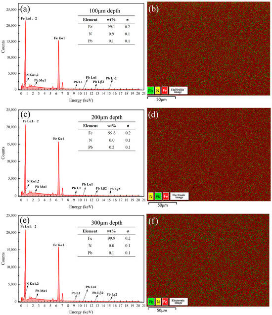
Figure 14.
Energy spectrum analysis results of the samples coated with Formula 2 at different depths. Energy spectrum and elemental composition table at depths of (a) 100 μm, (c) 200 μm, and (e) 300 μm; mapping fusion image at depths of (b) 100 μm, (d) 200 μm, and (f) 300 μm.
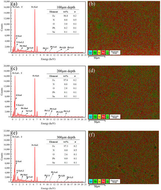
Figure 15.
Energy spectrum analysis results of the samples coated with Formula 3 at different depths. Energy spectrum and elemental composition table at depths of (a) 100 μm, (c) 200 μm, and (e) 300 μm; mapping fusion image at depths of (b) 100 μm, (d) 200 μm, and (f) 300 μm.
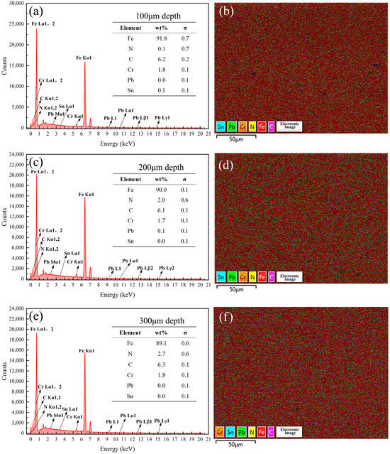
Figure 16.
Energy spectrum analysis results of the samples coated with Formula 4 at different depths. Energy spectrum and elemental composition table at depths of (a) 100 μm, (c) 200 μm, and (e) 300 μm; mapping fusion image at depths of (b) 100 μm, (d) 200 μm, and (f) 300 μm.
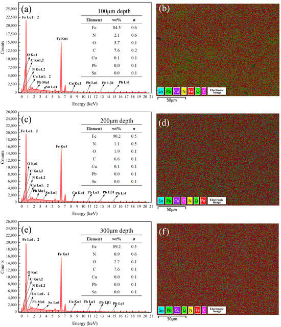
Figure 17.
Energy spectrum analysis results of the samples coated with Formula 5 at different depths. Energy spectrum and elemental composition table at depths of (a) 100 μm, (c) 200 μm, and (e) 300 μm; mapping fusion image at depths of (b) 100 μm, (d) 200 μm, and (f) 300 μm.
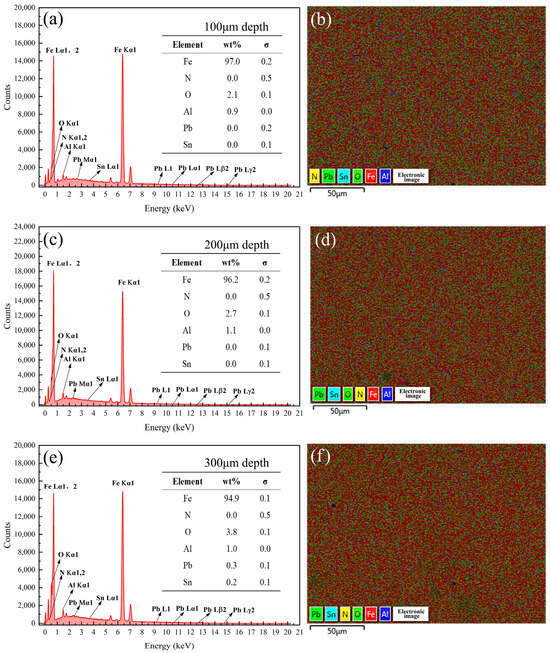
Figure 18.
Energy spectrum analysis results of the samples coated with Formula 6 at different depths. Energy spectrum and elemental composition table at depths of (a) 100 μm, (c) 200 μm, and (e) 300 μm; mapping fusion image at depths of (b) 100 μm, (d) 200 μm, and (f) 300 μm.
Table 4.
Nitrogen content at various depths of coatings with different formulations (%).
Analysis of Figure 16 in conjunction with Figure 8 revealed that no N was detected on the surface of the 38CrMoAl steel coated with Formula 4, while the N content gradually increased below the surface. This suggests that a nitriding layer formed in the 100–300 μm region. However, no distinct bright white nitriding layer was observed in Figure 3d, indicating that this region corresponds to the nitriding diffusion zone. Consequently, this sample exhibited the highest hardness. As shown in Figure 17, 1.5% of the N was detected on the surface of the 38CrMoAl steel coated with Formula 5, and a certain amount of N was also detected beneath the surface. However, the N content decreased with increasing depth. No distinct bright white nitrided layer was observed, indicating that this region corresponds to the nitride diffusion zone. As shown in Figure 18, no N was detected at any depth in the 38CrMoAl steel coated with Formula 6, indicating that this coating effectively prevented N infiltration. However, compared to Formulas 4 and 5, the O content was slightly higher. This was likely due to alumina forming a dense oxide film during nitriding, which inhibited N penetration.
4. Conclusions
In this study, the anti-nitriding effects of six different anti-nitriding coatings on 38CrMoAl steel were studied. The findings can be summarized as follows:
- (1)
- The six new anti-nitriding coating formulations developed in this study all demonstrated a certain degree of anti-nitriding performance. No Fe2₋3N phase was detected on the surface, and the hardness values of all the samples remained below 600 HV, which are significantly lower than the hardness achieved after nitriding. Nevertheless, only Formulas 2, 3, and 6 were deemed suitable for practical applications in production and daily use, as their average surface hardness was consistently below 320 HV, similar to the hardness of the substrate prior to nitriding and thus meeting the established anti-nitriding criteria.
- (2)
- Similarly to tin powder, lead powder exhibited the ability to prevent nitrogen infiltration. Both the pure lead formulation and tin/lead alloy coatings demonstrated superior anti-nitriding performance. Notably, the tin/lead and pure lead formulations exhibited higher hardness values when compared to the pure tin formulation, with an average hardness of less than 290 HV, similar to the hardness of the 38CrMoAl steel substrate. The concentrations of Sn and Pb detected on both the surface and interior of the samples were extremely low, not exceeding 0.2%. Additionally, the XRD analysis failed to detect the presence of these elements. These findings suggest that Sn and Pb formed a thin film on the sample surface that effectively inhibited nitrogen penetration, rather than reducing nitrogen ingress by occupying interstitial sites within the microstructure.
- (3)
- The incorporation of oxides into the tin–lead formulation significantly affected the anti-nitriding performance. Chromium oxide exhibited the weakest anti-nitriding effect, whereas aluminum oxide had the strongest effect. No nitrogen was detected on either the surface or cross-section of the aluminum oxide-based coating, with α-Fe and Fe-Cr alloy remaining the primary constituents. This suggests that the dense film formed by the tin/lead/aluminum oxide formulation effectively inhibited the interaction between nitrogen and iron.
Author Contributions
Conceptualization, Y.X. and Y.Y.; methodology, Y.X.; software, Y.Q.; validation, Y.X. and Y.Q.; investigation, Y.X.; resources, Y.Y.; data curation, Y.X. and Y.Q.; writing—original draft preparation, Y.X.; writing—review and editing, Y.Y.; supervision, Y.Y.; project administration, Y.Y.; funding acquisition, Y.Y. All authors have read and agreed to the published version of the manuscript.
Funding
This research was funded by Zhoushan Xinxing Machinery Manufacturing Co., Ltd. (21048003923).
Institutional Review Board Statement
Not applicable.
Informed Consent Statement
Not applicable.
Data Availability Statement
The data are contained within the article.
Conflicts of Interest
The authors declare no conflicts of interest.
Abbreviations
The following abbreviations are used in this manuscript:
| SEM | Scanning electron microscopy |
| EDS | Energy-dispersive spectroscopy |
References
- Chen, Y.; Song, L.; Zhang, C.; Ye, X.; Song, R.; Wang, Z.; Zhao, X.; Hu, J. Plasma Nitriding without Formation of Compound Layer for 38CrMoAl Hydraulic Plunger. Vacuum 2017, 143, 98–101. [Google Scholar] [CrossRef]
- Zhou, Y.-L.; Xia, F.; Xie, A.-J.; Peng, H.-P.; Wang, J.-H.; Li, Z.-W. A Review—Effect of Accelerating Methods on Gas Nitriding: Accelerating Mechanism, Nitriding Behavior, and Techno-Economic Analysis. Coatings 2023, 13, 1846. [Google Scholar] [CrossRef]
- Fu, Q.; Gui, X.; Gyawali, G.; Yang, Y.; Li, D.; Xiang, T.; Nouri, M.; Zhang, S. Improved Tribo-Corrosion Performance of Duplex Treatment on H13 Steel by Plasma Nitriding and CrAlN Coating. Surf. Interfaces 2025, 56, 105738. [Google Scholar] [CrossRef]
- Zhang, Y.; Yang, W.; Wang, A.; Fan, W.; Zhang, W.; Lan, Y. Modification and Corrosion Resistance of 38CrMoAl Steel by Laser Cladding-Ion Nitriding. Surf. Technol. 2024, 53, 135–143. [Google Scholar] [CrossRef]
- Liu, D.; You, Y.; Yan, M.; Chen, H.; Wang, C.; Li, R.; Hong, L.; Han, T. Characterization of Plasma Nitrided Layer at Different Atmosphere Conditions on 38CrMoAl Steel at 520 °C. China Surf. Eng. 2022, 35, 196–203. [Google Scholar]
- Wang, Y.; Yin, T.; Li, S. Effect of decarbonized layer on plasma nitriding of 38CrMoAl steel. Heat Treat. Met. 2020, 45, 194–198. [Google Scholar] [CrossRef]
- Wang, T.; Wang, Y.; Li, J.; Zhang, Y.; Wang, Z.; Tang, L. Microstructure, properties and thickness prediction of nitriding and laser hardening composite modified layer on 38CrMoAl steel surface. Mater. Mech. Eng. 2024, 48, 96–103. [Google Scholar]
- Liu, D.; You, Y.; Yan, M.; Chen, H.; Li, R.; Hong, L.; Han, T. Acceleration of Plasma Nitriding at 550 °C with Rare Earth on the Surface of 38CrMoAl Steel. Coatings 2021, 11, 1122. [Google Scholar] [CrossRef]
- Steinbacher, M.; Hoja, S. Optimization of Pre-Heat Treatment for Nitriding. Materials 2021, 14, 7766. [Google Scholar] [CrossRef]
- Yan, F.; Yao, J.; Chen, B.; Yang, Y.; Xu, Y.; Yan, M.; Zhang, Y. A Novel Decarburizing-Nitriding Treatment of Carburized/through-Hardened Bearing Steel towards Enhanced Nitriding Kinetics and Microstructure Refinement. Coatings 2021, 11, 112. [Google Scholar] [CrossRef]
- Fan, L.; Lv, Y.; Wu, L.; Zhang, S.; Wang, T.; Liu, F.; Ding, X.; Yao, J. Enhanced Nitriding of 38CrMoAl Steels with Laser Vibrational Excitation of Ammonia. Metall. Mater. Trans. A 2024, 55, 3302–3312. [Google Scholar] [CrossRef]
- Hong, H.; Xie, G.; Sun, L.; Yang, Y.; Zhang, Z.; Li, J.; Zhang, S. The Diffusion Behavior and Surface Properties of Catalytic Nitriding with LaFeO3 Film Prepared by the Sol-Gel Method. Surf. Coat. Technol. 2023, 467, 129720. [Google Scholar] [CrossRef]
- Feng, Z.; Zheng, J.; Liu, J. Negative pressure rapid nitriding process and performance of 38CrMoAl steel under vacuum induction. Trans. Mater. Heat Treat. 2017, 38, 128–133. [Google Scholar]
- O’Sullivan, B.J.; Kaushik, V.S.; Everaert, J.-L.; Trojman, L.; Ragnarsson, L.; Pantisano, L.; Rohr, E.; DeGendt, S.; Heyns, M. Effectiveness of Nitridation of Hafnium Silicate Dielectrics: A Comparison Between Thermal and Plasma Nitridation. IEEE Trans. Electron. Dev. 2007, 54, 1771–1775. [Google Scholar] [CrossRef]
- Zhou, L.; Zou, A.; Xia, T.; Gu, X. Effect of ammonia concentration on microstructure and properties of liquid phase plasma electrolytic nitrided layer of 38CrMoAl steel. Trans. Mater. Heat Treat. 2023, 44, 161–168. [Google Scholar] [CrossRef]
- Tong, W.P.; Han, Z.; Wang, L.M.; Lu, J.; Lu, K. Low-Temperature Nitriding of 38CrMoAl Steel with a Nanostructured Surface Layer Induced by Surface Mechanical Attrition Treatment. Surf. Coat. Technol. 2008, 202, 4957–4963. [Google Scholar] [CrossRef]
- Feng, Z.; Wei, K.; Wang, T.; Feng, Q.; Wang, S.; Jiao, L.; Ma, J.; Meng, D.; Li, J. Effect of Laser Scanning Speed on the Surface Characteristics and Wear Resistance of TiZrAlV Alloy via Laser Gas Nitriding. Surf. Coat. Technol. 2025, 500, 131909. [Google Scholar] [CrossRef]
- Zhao, X.; Wang, H.; Wang, B. Analysis of Abnormal Bright Spot on Gas Nitriding Surface. Heat Treat. Technol. Equip. 2024, 45, 49–51+64. [Google Scholar] [CrossRef]
- Włoczewski, M.; Jasiewicz, K.; Jenczyk, P.; Gadalińska, E.; Kulikowski, K.; Zhang, Y.; Li, R.X.; Jarząbek, D.M. AlCoCrFeNiTi0.2 High-Entropy Alloy Under Plasma Nitriding: Complex Microstructure Transformation, Mechanical and Tribological Enhancement. Metall. Mater. Trans. A 2025, 56, 2040–2056. [Google Scholar] [CrossRef]
- Zheng, H. Failure Analysis of the Turbine Valve Rod After Plasma Nitriding. Master Thesis, Qingdao University of Science & Technology, Qingdao, China, 2014. [Google Scholar]
- Tang, Q. Study on Nitriding Process of Hi-B Steel in Low-Temperature Procedure. Master Thesis, Wuhan University of Science and Technology, Wuhan, China, 2017. [Google Scholar]
- Huang, K.; Zheng, Z.; Lin, C.; Huang, W.; Zhang, J.; Chen, X.; Xiao, J.; Xu, J. Microstructure Characterization and High-Temperature Wear Behavior of Plasma Nitriding Mold Steel. Surf. Coat. Technol. 2024, 492, 131210. [Google Scholar] [CrossRef]
- Lu, W.; Liu, X.; Li, Y.; Huang, H. Effect of Granular Bainite in 38CrMoAlA Steel on Microstructure and Property of Nitrided Case. Heat Treat. 2006, 04, 28–32. [Google Scholar]
- Yang, X.; Liu, J. Continuous Cooling Transformation of 38CrMoAl Steel. Met. Mater. Metall. Eng. 2019, 47, 39–41. [Google Scholar]
- Liu, H.; Zhang, L.; Li, F.; Zhang, C.; Mao, P.; Li, C. Austenite grain growth behavior of 38CrMoAl steel. Heat Treat. Met. 2020, 45, 38–42. [Google Scholar] [CrossRef]
- Pan, Y. Determination of nitrided layer depth based on the corresponding relationship of 38CrMoAl screw barrel matrix hardness with nitriding performance. J. Mech. Electr. Eng. 2015, 32, 1348–1351. [Google Scholar]
- Jin, L.; Wu, Z.; Cheng, X.; Li, X.; Fang, M. Fracture failure analysis of 38CrMoAl steel piston rod of hydro-pneumatic spring. Heat Treat. Met. 2023, 48, 285–292. [Google Scholar] [CrossRef]
- Lan, Y.; Zhang, Y.; Peng, Y.; Wang, A.; Gao, Y.; Yang, W.; Fan, W.; Zhang, W.; Liu, Y. In-Situ Synthesis of Dual-Phase Nitrides and Multiple Strengthening Mechanisms in FeCoCrNiAl 0.5 High Entropy Matrix Composite Coatings by Laser Cladding and Plasma Nitriding. J. Alloys Compd. 2024, 990, 174400. [Google Scholar] [CrossRef]
- Sun, Y.; Liu, W.; Yu, X.; Wei, Y.; Su, Y.; Wang, Q.; Na, Y. Effect of Compound Treatment of Laser Shock Peening and Nitriding on Wear Resistance of M50 Steel. J. Mater. Eng. Perform. 2025, 34, 10591–10600. [Google Scholar] [CrossRef]
- Fan, L.; Bao, X.; Wang, T.; Wu, L.; Zhang, S.; Zhao, T.; Sun, T.; Ran, L.; Yao, J. Effect of Laser Excited Ammonia on Microstructure and Hardness of nitriding 38CrMoAl Steel (Invited). Infrared Laser Eng. 2024, 53, 61–72. [Google Scholar]
- Naima, H.; Lamine, D.M.; Laurent, B. Precipitation during the Nitriding in Fe-Cr-C Steels. Mater. Today Proc. 2018, 5, 17501–17514. [Google Scholar] [CrossRef]
Disclaimer/Publisher’s Note: The statements, opinions and data contained in all publications are solely those of the individual author(s) and contributor(s) and not of MDPI and/or the editor(s). MDPI and/or the editor(s) disclaim responsibility for any injury to people or property resulting from any ideas, methods, instructions or products referred to in the content. |
© 2025 by the authors. Licensee MDPI, Basel, Switzerland. This article is an open access article distributed under the terms and conditions of the Creative Commons Attribution (CC BY) license (https://creativecommons.org/licenses/by/4.0/).