1. Introduction
Pipelines, as the fastest, most reliable, and most economical means of transporting oil and natural gas, are regarded as a national energy lifeline project, and the safety and reliability of their structure and operation have become increasingly prominent, attracting widespread attention [
1,
2,
3,
4,
5]. For oil and gas transmission pipelines that are thousands of kilometers long, approximately 98% are laid underground; however, because buried pipelines are in direct contact with the surrounding soil and rock, they are greatly influenced by geological strata, and geological hazards can cause pipeline damage and failure. Studies [
6,
7,
8] have shown that among all geological hazards, severe ground shaking is the primary cause of damage to surface structures and to buried pipelines in urban infrastructure, and it can sometimes induce buckling deformation in pipelines, leading to potential safety risks during pipeline operation.
Due to the highly complex service conditions of oil and gas pipelines, buckling deformations under compression are typically difficult to predict, and the resulting folds are strongly influenced by the material properties and pipeline specifications. Research on predictive formulae for the critical buckling strain of steel pipes has a history of more than 50 years. In current standards, the formulae commonly used for predicting the limit compressive strain are found in the Det Norske Veritas (DNV) [
9] and Canadian Standards Association (CSA) [
10] codes. Traditional theoretical analysis of pipeline buckling deformation is not highly accurate, the regularity of wrinkle formation is not well-defined, and experimental research on this phenomenon is associated with high costs and long durations [
11,
12]. In 1927, Brazier [
13] discovered the extreme buckling phenomenon of pipelines. In 1992, Ju et al. [
14] studied the influence of the diameter-to-thickness ratio (D/t) of pipes on local buckling behavior. In 2005, Iflefel et al. [
15] investigated the effect of dent depth on the ultimate bending moment of pressurized pipelines under bending loads. They found that when a dent occurs on the compressive side of the pipeline, it is more dangerous than when it occurs on the tensile side, and the buckling modes differ under these two conditions. In 2007, Blachut et al. [
16] introduced dents in five small-diameter pipelines and conducted four-point bending tests to analyze the buckling behavior of pressurized pipelines with dents. Comparison showed that the simulation results of the denting process agree well with the experimental results, whereas the simulated buckling load is lower than the pipeline’s critical buckling load. With the breakthrough development of computer technology, numerical simulation techniques have been increasingly applied to pipeline–soil analysis. In particular, the finite element method has gradually been widely used in safety studies of buried pipelines under permanent ground deformations. In 2012, Beak et al. [
17] used Abaqus to simulate the ultimate bending moment of a large-diameter API-X65 pipeline. Cai et al. [
18], based on experimental data and numerical results, proposed an empirical formula for calculating the ultimate bending moment when a planar dent is located on the compressive side of the pipeline. Bai et al. [
19], based on formulae for intact pipelines and considering the effects of dent angle and position, developed a predictive model for the ultimate bending moment of dented pipelines. Yu et al. [
20] used a finite element model to study the failure behavior of pipelines under axial tension and torsion.
Sun et al. [
21] investigated the failure pressure of X46/X60/X80 grade pipelines with corrosion defects of various geometries and orientations using finite element modeling, with a focus on the influence of defect interaction on pipeline integrity. Their study revealed that failure pressure decreases with increasing interaction between defects, with longitudinal defects exhibiting a wider interaction range, while circumferential spacing had a weaker effect. Overlapping defects significantly reduce failure pressure compared to single-layer defects, and increasing defect depth and length intensifies the interaction effect, further weakening the pipeline’s load-bearing capacity. Zhang et al. [
22] employed finite element analysis to model B-type sleeve fillet welds and analyzed stress and stress concentration factors under varying crack lengths, depths, and angles. The results showed that the maximum stress concentration factor increases with crack length and depth, and initially increases then decreases with the increase in crack inclination angle. Robert et al. [
23] conducted finite element analysis to compare pressurized and non-pressurized annular sleeves, finding that maximum stress occurred at the weld toe and root. They also developed a model linking pressure fluctuations to weld stress and proposed a fatigue crack propagation prediction algorithm. Their study suggested that the decision to drill holes in pipelines should consider operating pressure, dimensional parameters, and residual stress distribution. Liu et al. [
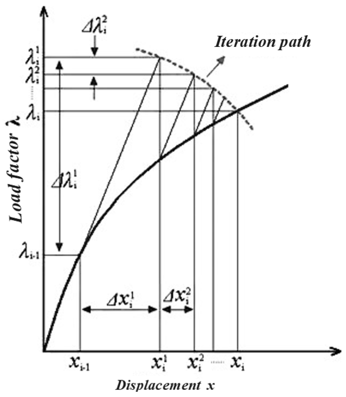
24] developed a three-dimensional parametric finite element model of the pipeline–soil system using the finite element method. Arc-length and nonlinear stabilization algorithms were used to simulate the strain-softening behavior after pipeline plastic failure. Additionally, the effects of soil type and model size on maximum pipeline deflection were investigated. The proposed finite element approach provides a basis for safe design, failure assessment, and engineering acceptance standards for pipeline buckling failure.
The sleeve repair technique was first introduced in the 1970s by the British Gas Corporation. This method involves externally installing a steel sleeve at the damaged section of a pipeline to restore structural strength or seal ability. Its core principle is to allow the sleeve to share the pipeline load or seal the leakage, thereby extending pipeline service life. Sleeve repair has now become a relatively mature technology for addressing various pipeline defects such as internal and external corrosion [
25], dents, buckling wrinkles, and fatigue cracks [
26]. Currently, commonly used sleeve repair types for oil and gas pipelines include Type A sleeves, Type B sleeves, and epoxy sleeves.
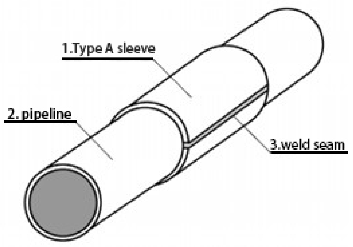
The conventional Type A sleeve typically consists of a pair of semi-cylindrical steel plates covering the defect area, joined by longitudinal side welds. The sleeve structure is illustrated in
Figure 1. A key feature of this design is that it does not require welding onto the pipeline itself, making the repair process relatively simple. This type of sleeve is non-pressure-bearing and can provide reinforcement to the defected area, but it does not affect axial stress in the pipeline. It is mainly applicable to the repair of wall damage, arc burns, dents in the pipe body, dents in longitudinal welds, and cracks, but is unsuitable for repairing circumferential defects, leakages, or defects prone to further development.
In the figure, 1 represents the traditional Type A sleeve, 2 denotes the transmission pipeline, and 3 indicates the axial side weld seam.
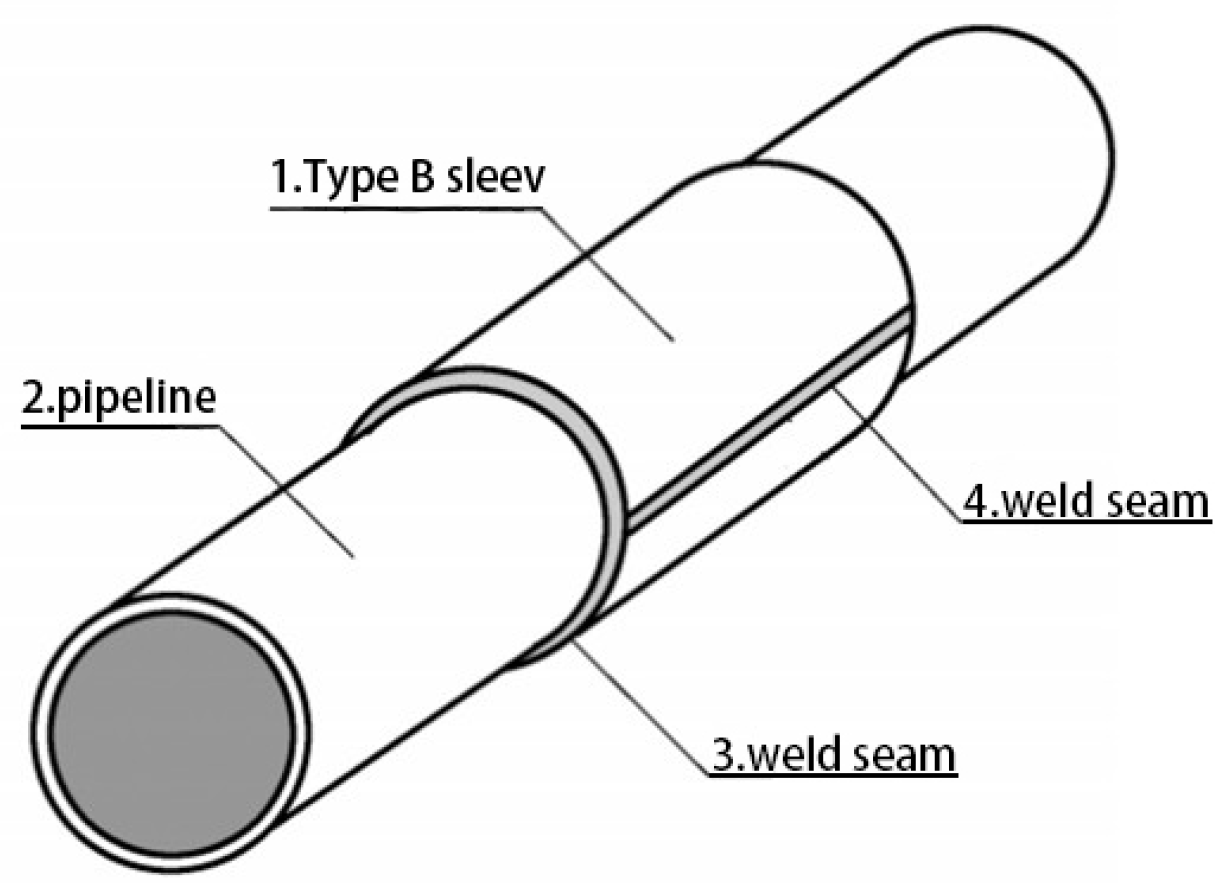
The structural design of traditional Type B sleeve repair is similar to that of Type A sleeve repair. Both utilize two semi-cylindrical shells made from steel plates that cover the defect area on the pipeline, with the center of the axial length of the defect aligned at the midpoint of the sleeve length. The two sleeve halves are welded together along two longitudinal side seams. A key distinguishing feature of the Type B sleeve is that its ends are fillet-welded to the transmission pipeline. The basic structural form of the Type B sleeve is shown in
Figure 2.
As a pressure-bearing sleeve, the Type B sleeve is designed to withstand internal pressure no less than the pipeline’s design pressure; it also resists axial stress induced by pipeline bending or axial loads. The Type B sleeve is suitable for repairing a wide range of defects, including leaks and circumferential flaws that cannot be addressed by Type A sleeves, making it a critical pipeline defect repair technology. Due to the requirement for circumferential fillet welding, the construction process of Type B sleeve repair is more complex than that of Type A sleeve repair [
27]. However, compared to pipe replacement methods, Type B sleeve repair offers significant advantages, including shorter repair time, relatively lower costs, and reduced environmental impact.
In the figure, 1 represents the traditional Type B sleeve, 2 denotes the transmission pipeline, 3 indicates the axial side weld seam, and 4 is the circumferential fillet weld.
In the field of Type B sleeve repair technology for pipelines, both domestic and international scholars have conducted a series of systematic studies and practical applications. In developed countries—particularly the United States and Canada—research teams have long focused on the engineering applications and performance improvement of oil and gas pipeline repair technologies. Their core research areas primarily concentrate on improving repair efficiency, reducing repair costs, and ensuring repair quality. Xu et al. [
28] investigated the effects of Type B sleeve welding on X80 pipeline steel through physic-chemical property testing and corrosion experiments. They found that welding did not significantly alter the base material’s physical and chemical properties. The main corrosive agents identified were O
2, SO
42−, and Cl
−, and both the heat-affected zone and the sleeve material showed increased susceptibility to degradation with extended corrosion time. Wang et al. [
29] applied X70 steel Type B sleeves and associated technologies to repair circumferential weld defects in φ1016 mm X80 grade gas transmission pipelines. Their verification process—using hydrostatic cycling, non-destructive testing, macroscopic inspection, and mechanical property testing—showed that under high-pressure fluctuations, defects did not propagate, weld defects were well controlled, performance metrics met standards, though errors were observed in PAUT (Phased Array Ultrasonic Testing) results. They concluded that this technique ensures long-term safe operation of defect-containing pipelines and recommended its broader application in oil and gas infrastructure. Ma et al. [
30] evaluated the reliability of using Type B steel sleeves to repair circumferential weld defects in X80 pipelines. Results indicated that in cases of circumferential weld leakage, the load-bearing capacity of the Type B sleeve effectively maintained pipeline operational safety. However, welding heat significantly affected the surface material properties of the main pipeline. The influence of longitudinal welds was found to be smaller than that of circumferential fillet welds. Grain coarsening was observed in the heat-affected zone of the fillet weld, resulting in increased hardness and a 5.5% reduction in yield strength in the lower section of the main pipe beneath the fillet weld. Surface cracking occurred during bend testing, indicating a certain degree of service risk.
Currently, studies on the buckling behavior of pipelines under bending loads have mainly focused on the combined effects of wall thickness, outer diameter, and dents, while research on the influence of internal pressure on pipeline buckling behavior remains limited. Based on this, the present study investigates the buckling deformation behavior of buried pipelines under external forces. It analyzes the deformation patterns of API-X80 pipelines with varying outer diameters, wall thicknesses, and internal pressure conditions, aiming to provide a theoretical basis for understanding buckling failure mechanisms under service conditions. Simultaneously, a pipeline repair method based on response surface methodology and genetic algorithm has been proposed [
31].
Despite extensive studies on pipeline local buckling under bending, limited attention has been given to the combined effects of internal pressure and bending on wrinkle formation and protrusion development, especially in high-grade pipelines like API-X80. Furthermore, while sleeve repair techniques are widely applied, few studies have focused on optimizing B-type sleeve structures tailored to accommodate pressure-induced wrinkling. In this context, this study addresses the coupled bending pressure-induced wrinkle behavior of X80 pipelines and proposes a convex B-type sleeve design optimized through response surface methodology (RSM) and genetic algorithm (GA), filling a current gap in the literature and providing a reference for practical repair designs.
