Article

Can a-C:H-Sputtered Coatings Be Extended to Orthodontics?

by
António Fróis
1,2,
Ana Sofia Aleixo
1,
Manuel Evaristo
1,
Ana Cristina Santos
2,3 and
Cristina Santos Louro
1,*
1
CEMMPRE, Department of Mechanical Engineering, University of Coimbra, 3030-788 Coimbra, Portugal
2
Coimbra Institute for Clinical and Biomedical Research/Center for Innovative Biomedicine and Biotechnology (iCBR/CIBB), Biophysics Institute, Faculty of Medicine, University of Coimbra, 3000-548 Coimbra, Portugal
3
Area of Environment Genetics and Oncobiology (CIMAGO), 3000-548 Coimbra, Portugal
*
Author to whom correspondence should be addressed.
Coatings 2021, 11(7), 832; https://doi.org/10.3390/coatings11070832
Submission received: 15 June 2021 / Revised: 2 July 2021 / Accepted: 6 July 2021 / Published: 9 July 2021
(This article belongs to the Special Issue Advances in Hard Coatings: Production, Properties and Applications)

Abstract

:
Hydrogenated amorphous carbon (a-C:H) coatings are attractive materials for protecting metallic surfaces in extreme biological environments like the human oral cavity, due to the unusual combination of mechanical properties, superior bioinertness, and relative easier and cheaper production. In this work, two a-C:H coatings were deposited on AISI 316L substrates by reactive magnetron sputtering with two CH4 flows to assess if this outstanding system could extend its application range to orthodontics. A 30-day immersion test in Fusayama-Meyer artificial saliva was conducted to mimic an extreme acidic intraoral pH. Extracts were quantified and used to perform in vitro assays with mono- and co-cultures of macrophages and fibroblast to assess cell viability, while mechanical and structural behaviors were studied by nanoindentation and visible Raman. The empirically estimated H contents of ~28 and 40 at.% matched the hard and soft a-C:H coating regimes of 18 and 7 GPa, respectively. After immersion, no important structural/mechanical modifications occurred, regardless of the H content, without corrosion signs, delamination, or coating detachment. However, the adhesion-promoting Cr-based interlayer seems to reduce corrosion resistance via galvanic coupling. The highest biocompatibility was found for a-C:H coatings with the lowest H content. This study indicates that sputtered a-C:H are promising surface materials in orthodontics.

1. Introduction

Fixed orthodontic appliances are the first choice to treat malocclusions, that is, “crooked teeth” [1], and biometals like stainless steel (SS) and Nitinol (NiTi) thrive for manufacturing brackets, archwires, bands, tubes, and other components [2]. Metallic orthodontic materials are preferred over other classes of materials due to their wide range of properties, including superior in vivo mechanical behavior [2]. However, the mouth is an extreme environment: saliva, diet, oral hygiene procedures, and biofilm activity frequently lead to chemical composition, pH, and temperature variations. [3,4,5,6,7]. This open ecosystem, which hosts more than 700 species and subspecies of bacteria, fungi, and viruses [3], ultimately corrodes biomaterials in several ways [8,9,10]. For instance, low pH values [11], and F and Cl ions [12] easily induce pitting corrosion, while biofilm activity generates microgalvanic cells [3]. Furthermore, backet and archwires are tightened under load with elastic or metallic ligatures, causing fretting [3,10] and crevice [13] corrosion.
The inevitable end result of these corrosion processes is the release of metallic species (e.g., Ni, Cr, Co, Fe, Ti, usually as ions) into the oral cavity [8,9]. Depending on their reactivity to biomolecules [14], some metallic species are toxic or can induce allergic reactions [8,9,15]. Among them, Ni stands out: the International Agency for Research on Cancer (IARC) classifies Ni (II) and all Ni compounds as carcinogenic or potentially carcinogenic to humans [16].
Ni is also a well-known potent allergen capable of triggering hypersensitive reactions [17]. Reported intra- to extra-oral, subtle to severe symptoms of allergy to Ni-containing orthodontic components include: burning sensation, generalized urticaria, and widespread eczema [9,18,19,20,21], while in general, the impact of Ni-related allergies in orthodontic seems low but non-consensual [8,9,22], Ni allergies may be underdiagnosed: symptoms can be subtle, difficult to detect, and easily attributed to poor oral hygiene or mechanical injuries [21,22]. Nonetheless, allergies do occur, forcing orthodontists to replace Ni-containing components with “Ni-free” alternatives, stop the treatment, or even refer the patient to a physician for appropriate medication (e.g., antihistamines, anesthetics, or corticosteroids) [18,19,20,21].
Despite concerns, Ni-containing alloys, like NiTi (~50 at.%) and austenitic SS (8–18 wt.%), are unquestionably important in orthodontics, since multiple concerns still limit clinicians’ acceptance and widespread use of metal-free alternative material solutions [1,2,23]. A solution proposed by Surface Engineering is to try to improve interfacial properties, taking advantage of the already-optimized bulk properties. Two paths are actively explored: surface modification (e.g., ion implantation or induced passive oxide film), and protective coatings [24]. However, solutions in clinical practice are still scarce.
Amorphous carbon films, usually termed diamond-like carbon (DLC) films [25], are extensively used and/or studied as protective coatings for several industrial applications [26], including to prevent tribocorrosion of metallic parts [27], and clearly attractive for biomedical applications due to their excellent biocompatibility [28]. The hydrogenated forms of amorphous carbon, a-C:H, are a major group of DLC materials with H contents up to 60 at.% [29]. Together with H content, the sp2/sp3 C–C bond ratio governs the final properties of DLCs [25], which are further tunable by doping [27]. One of the major disadvantages of DLC coatings is the low long-term adhesion to substrates [30], which can be improved by depositing a metallic-based interlayer between the substrate and the C-based coating [27,31].
To the authors’ knowledge, little research has been carried out in orthodontics when compared to other medical fields (e.g., orthopedics [30,31]), despite encouraging results [32,33,34]. Therefore, this work aims to study the H content effect on the overall biological and mechanical behavior of a-C:H sputter-deposited coatings on an AISI 316L (SS316L) bioalloy. For that, two reactive CH4 gas flows were selected, matching the diamond and graphitic regimes of the a-C:H coatings [29,35], included in the hard and soft categories [25], respectively. Precise characterization, before and after the 30-day immersion test in acidic Fusayama-Meyer artificial saliva, was performed, presented, and discussed. In addition, the cell viability was quantified both with mono- and co-cultures of fibroblasts and macrophages. The highest biocompatibility was found for the a-C:H coatings with the lowest H content.

2. Materials and Methods

2.1. Synthesis of a-C:H Coatings

The reactive direct current magnetron sputtering technique was used to deposit a-C:H coatings (Teer Coating equipment, TEER Coating Ltd., Worcestershire, UK) onto SS316L round and square-shaped substrates. The SS316L surface preparation followed the “traditional” approach for coating deposition: samples were grinded with SiC sandpapers (P500 to P2000), and mirror-polished with 3 µm diamond suspension. All samples were ultrasonically cleaned in an acetone/alcohol bath and dried by hot air flow. Two film sets were produced with CH4/Ar flow ratios of 1:9 and 1:5, corresponding to CH4 flows of 5 and 10 sccm, respectively. Preceding the external a-C:H layer deposition, substrates were sputter-etched with Ar+ bombardment for 30 min to remove surface impurities, followed by a Cr-based buffer layer formation of approximately 300 nm (Cr and C targets power of 2000 W and 50 W, respectively) to improve adhesion of the coatings to the metallic substrates. The deposition parameters were maintained constant: total working gas pressure of 0.6 Pa, Ar flow of 46 sccm, negative substrate bias of −50 V, and 2 graphite targets (99.9% purity) with a constant power of 1750 W. The deposition time was selected to achieve a total coating thickness close to 1 µm.
Hereafter, the coatings will be termed a-C:5H and a-C:10H, according to the selected reactive gas flow.

2.2. Coatings Characterization

The surface and cross-section morphologies were analyzed by high-resolution scanning electron microscopy (SEM-ZEISS Merlin Compact/VP Compact, Oberkochen, Germany). Both chemical composition and elemental distribution maps were obtained through energy dispersive spectroscopy (EDS-coupled Oxford X-Max Instruments to the SEM system, Oxford Instruments, Oxford, UK).
Structure and chemical bonding were studied through visible Raman spectroscopy (LabRAM HR Evolution, Horiba, 532 nm wavelength, Kyoto, Japan). Raman spectra were deconvoluted in the D and G bands by using Gaussian-type fitting. Two additional peaks at 1200 and 1500 nm were considered for the a-C:10H films, matching the most frequently used bands in the fitting process [36].
The C–C sp3 bonding fraction was calculated using Equation (1) [37]:
% sp 3 = 0.24 48.9   w G 0.1580 ,
where w G is the position of the G peak in the inverse of micrometer unit (µm−1). Moreover, the H content of the coatings was empirically estimated from the Raman spectra in accordance with Casiraghi et al. [29] by using Equation (2):
[ H   a t . % ] R a m a n = 21.7 + 16.6 log m I G   μ m ,
where m is the slope of the photoluminescence (PL) background and IG is the intensity of the G peak. This equation is valid for the limited range of 20–45 at.% H [29].
The average surface roughness (Ra) was measured by atomic force microscopy (AFM - Veeco DiInnova, Barcelona, Spain) running in intermittent mode (vibration frequency of 11 to 19 kHz) on a 2 × 2 μm2 area. A contact angle system OCA equipment (DataPhysics Instruments GmbH, Filderstadt, Germany) was used to assess the static contact angles applying distilled water (at least three measurements per sample).
Mechanical properties were evaluated by depth-sensing nanoindentation, using a Berkovich indenter (MicroMaterials NanoTest platform, Wrexham, UK). Each hardness value was calculated from an average of 20 indentations performed under a normal load of 5 mN, with an indentation depth below 10% of the coating thickness.
Following Singha et al. [37], the H contents of the coatings were alternatively estimated from their hardness knowledge by using Equation (3):
Hardness   GPa = 44.195 0.93 × H   content   at . % .

2.3. Saliva Immersion Test

Samples were immersed in a modified Fusayama-Meyer artificial saliva (Table 1) at a constant temperature of 37 °C for 30 days (stirred once a day on a digital shaking platform). According to standard ISO 10271 [38], a ratio of 1 cm2 of sample surface area per 10 mL of solution was preserved, and the pH was set at 2.3. After immersion, samples were ultrasonically cleaned in alcohol and air-dried prior to characterization. Released Ni, Cr and Fe ions were measured in duplicates by inductively coupled plasma-optical emission spectroscopy (ICP-OES) in a Horiba Jobin-Yvon Ultima apparatus (Edison, NJ, USA). The average metal release rates (per day and per cm2) during the immersion times were estimated. Uncoated SS316L samples were used as reference.

2.4. In Vitro Cytotoxicity

2.4.1. Cell Cultures

NIH/373 (ATCC® CRL-1658TM) fibroblasts [39] (the most used fibroblasts in biomedicine and pharmacy [40,41]) and Wistar rat peritoneal macrophages (collected in-house as described elsewhere [42]) were incubated in Dulbecco’s Modified Eagle’s Medium (DMEM–Gibco® 1×, 11966-025, ThermoFisher Scientific, Altrincham, UK) supplemented with 5% fetal bovine serum (FBS–Sigma-Aldrich®, F7524, St. Louis, MO, USA), 1% L-glutamine (L-Glutamine 100×, 200 mM, XO55O-100, Biowest, Nuaillé, France, USA), and 1% antibiotics (penicillin and streptomycin, Lonza Pen Srep, Amphotericin, B 100×, 17-745, Lonza Walkersville Inc., Walkersville, MD, USA) at 37 °C, 5% CO2, and 95% humidity (Binder incubator, CB 150, Uster, Switzerland).

2.4.2. Extract Testing

In the present work, the cytotoxicity assays were based upon extract testing, according to ISO 10993-5 [43] and by adapting the protocol developed and followed by Costa et al. [44]. Fibroblasts and macrophages were separately seeded or co-cultured in 48-well flat-bottom plates (Corning Inc Costar®, 3548, Corning, NY, USA) in sterile conditions (flow laminar chamber, Heraeus Holten, HBB 2448, LabExchange, Germany). For both monocultures and co-cultures, a total number of 2.6 × 10³ fibroblasts and/or 5 × 10⁴ macrophages per well were used. For controls, 800 µL of culture medium was added to each well, while for the extracts 100 µL of each extract (a-C:5H or a-C:10H) or artificial saliva were used plus 700 µL of complete culture medium, to obtain the same total volume (800 µL). Plates were prepared to be incubated for 3 and 5 days, under the previously described conditions (37 °C, 5% CO2, 95% humidity).

2.4.3. MTT Assay

After each incubation period, the MTT (3-[4,5-dimethylthiazol-2-yl]-2,5-diphenyltetrazolium bromide) assay was conducted to quantify cellular viability [45]. In aseptic conditions, the content of each well was removed, and 720 µL of fresh complete culture medium and 80 µL of MTT were added. The plates were placed inside the incubator for 4 h in the previously described conditions. Afterwards, the solution of each well was removed, and 800 µL of isopropanol were added to stabilize the formazan crystals for 15 min over (at room temperature over the bench). Finally, the absorbance was measured at 570 nm with a reference filter of 620 nm using a spectrophotometer (Biotek Synergy HT, Winooski, VT, USA). After the MTT test, optical contrast phase microscopy (OPCM) micrographs of fibroblasts provide further insights (AE31 microscope, Motic, with a Moticam Pro 285A, Schertz, TX, USA and software Motic Images Plus 2.0 software).

2.5. Statistical Analysis

Statistical analysis was performed using the SPSS Statistics software (version 25) from IBM Corporation, and graphs were obtained with the Prism GraphPad software (version 5.01). Since controls varied between assays, the MTT values were expressed as percentages of the average control value of each experiment. Cell viability between the groups was compared by using the non-parametric Kruskal–Wallis test. To compare the cellular viability percentage values between two specific groups, the Benferroni correction for multiple comparisons was chosen. Statistically significant differences were determined for a significance level of p < 0.05.

3. Results and Discussion

3.1. As-Deposited Characterization

Table 2 summarizes the main characteristics of both sputter-deposited a-C:5H and a-C:10H coatings.
Chemical composition and elemental cross-section distribution maps obtained by SEM/EDS revealed a homogeneous outer C-containing layer for both coatings, followed by a Cr-rich buffer interlayer onto the Si substrate, Figure 1. Despite all precautions, including the intended initial low vacuum pressure of ~10−3 Pa and the substrate surface cleaning with Ar+ sputtering etching, some residual oxygen contamination was detected, particularly for a-C:10H (see Table 2). Nevertheless, one can conclude that this low impurity content is preferentially located in the adhesion interlayer region, as shown by the O Kα distribution maps in Figure 1, due to the high affinity of Cr for O, decreasing towards the external a-C:H surfaces. Some Ar subplantation was also identified in the a-C:5H coatings (see Table 2, EDS maps not shown), as mentioned in other research [46,47], since Ar was the carrier gas during the sputtering film formation.
Concerning the as-deposited morphology, Figure 1, a well-defined columnar Cr-based adhesion layer of ~300 nm, contrasts with a thicker external a-C:H layer with the typical cauliflower-like plan-view morphology [10,48,49,50]. Few conic defects—recognized in other research reports [51,52]—were identified in this study.
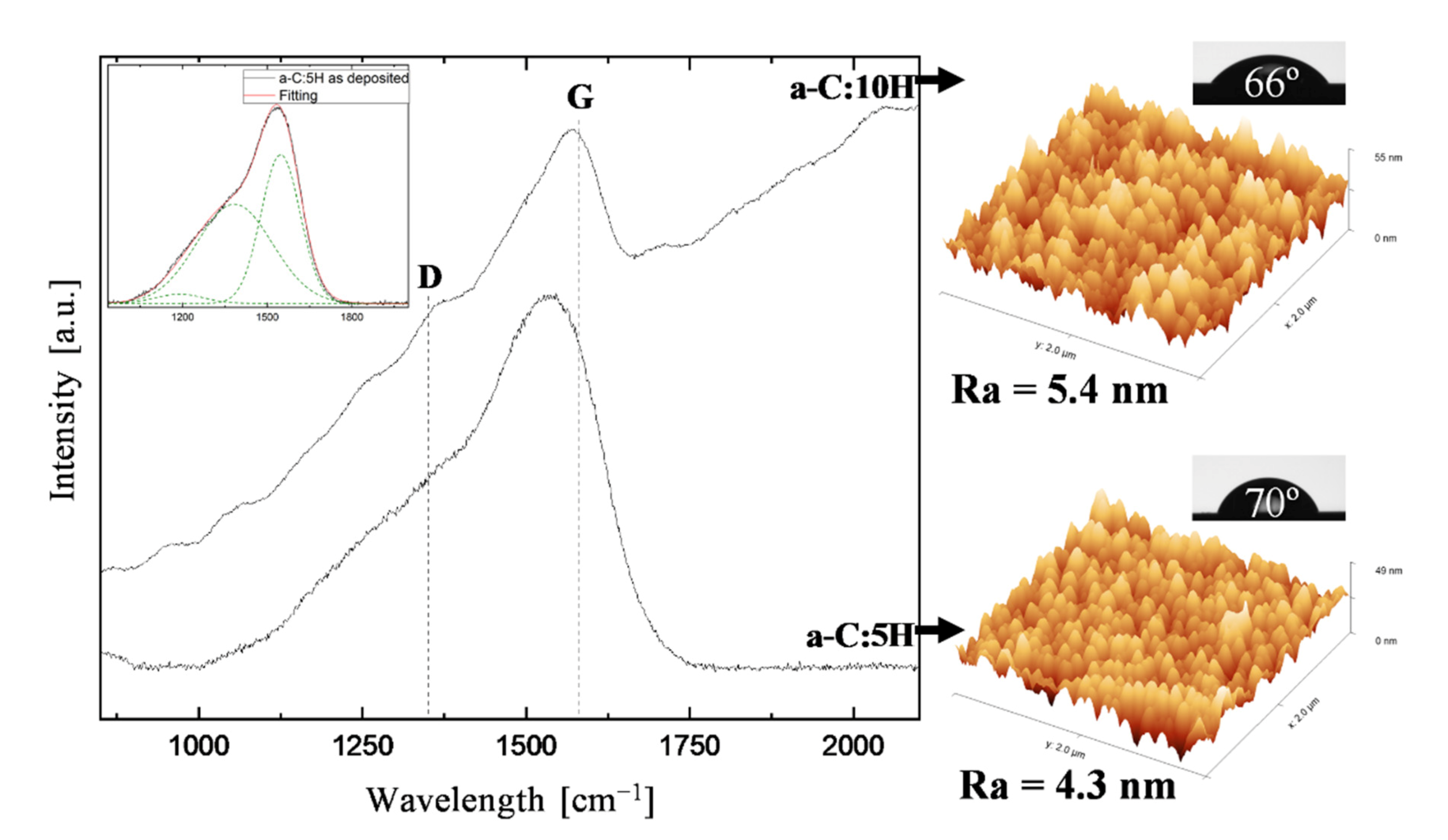
Visible Raman spectra present dissimilar structural features, Figure 2, evidencing the role of the H content during the a-C:H films formation. The spectra of the a-C:10H coatings exhibit a prominent PL background in contrast to a-C:5H. This is a well-established signature of hydrogenated amorphous carbon films, with H contents higher than ~20–25 at.%. Close to or below this range, the PL influence is almost or completely null; for higher values, PL background increases exponentially, obscuring the visible Raman spectra near or above 40–45 at.% [29,37,53]. According to Marchon et al. [53], this effect is caused by the electron/hole pairs within the sp2-rich clusters, and increases due to the progressive saturation of non-radiative recombination sites (e.g, carbon dangling bonds), resulting in more CHx (x = 1,2,3) terminations and polymeric-like bonds. A higher H content is therefore expected by increasing the CH4/Ar flow ratio from 1:9 to 1:5. In fact, the estimated H content for a-C:10H samples by applying Equation (2) was 46 at.% (Table 2). In contrast, the PL background is absent for the a-C:5H coatings, Figure 2, evidencing an H content below 25 at.%. Similar results were obtained in a previous work by the authors [46].
For a-C:5H coatings, a value of 28 at.% H was predicted from Equation (3), in agreement with its superior nanohardness of 18 GPa (Table 2); for the softer a-C:10H coatings (7 GPa), a higher H content of 40 at.% was estimated, agreeing with the predicted Raman PL background (Equation (2)). As mentioned before, higher H contents modify the C–C bonding by terminating double bonds of carbon as C(sp3)–Hx (x = 1,2,3) without increasing the C–C sp3 fraction of the films. Therefore, hardness decreases with increasing H content [37,46], corroborating the mechanical behavior evaluated by nanoindentation.
Casiraghi et al. [29] presented a classification for a-C:H coatings based on the information extracted from the Raman analysis, and deeply related to H and sp3 contents. According to this classification, the a-C:H with an H content ranging from 20 to 40 at.% are named Diamond-Like a-C:H (DLCH). DLCH coatings show hardness values up to around 20 GPa, and an sp3 range of 40%–60% [54], matching the obtained data for a-C:5H: hardness of~18 GPa, sp3 ~40%, and an estimated H content from Equation (3) of ~28 at.% (see Table 2).
For classifying the a-C:10H coatings, however, it is necessary to analyze another noticeable Raman feature in Figure 2: the deviation of the denoted G and D bands, accepted to be centered at around 1520–1570 cm−1 and 1350 cm−1, respectively [29,36]. The peak fitting with Gaussian-type bands revealed a small decrease of the D/G peak intensity ratio, I(D)/I(G), and a shift of the G band position to higher wavelength values with increasing H content (Figure 2 and Table 2). Apparently, such behavior contradicts the expected decrease on both the position of G and the I(D)/I(G) ratio when increasing H content above 20 at.%—the Polymer-Like a-C:H (PLCH) category proposed by Casiraghi et al. [29]. Nevertheless, the authors distinguish another group, which corresponds “to PLCH containing sp2 rings or to a highly hydrogenated GLCH [Graphite-Llike a-C:H]”—GLCHH. This peculiar case exhibits high H contents (~30–40 at.%), low hardness and sp3 contents around 30% [29]. In this work, an sp3 content of ~27.6% and an H content of ~46 at.% were calculated from Equations (1) and (2), respectively, while the obtained hardness value of ~7 GPa corresponds to an H content of ~40 at.% from Equation (3), agreeing with this classification. The a-C:5H and a-C:10H coatings produced in this study can, therefore, be included in the DLCH and GLCHH categories, respectively.
Finally, the highest contact angle values were obtained for the as-deposited a-C:5H, a mean value of 70°, comparable to those observed by several authors on DLC coatings [25,55,56,57]. In fact, 70° has been considered the angle above which a surface is named hydrophobic, i.e., the limit between hydrophobic and hydrophilic surfaces [58]. Nonetheless, Berg’s limit prefers a value of 65°, referring to the minimum detectable hydrophobic forces and separating hydrophilic (θ < 65°) from hydrophobic (θ > 65°) surfaces [59,60]. The as-deposited a-C:10H coatings exhibited a slightly lower contact angle, 66°, compared with a-C:5H samples, but still above Berg’s limit. The AFM roughness value, Ra, for a-C:10H coatings could justify this difference due to the slightly higher Ra values: 4.2 vs. 5.4 nm (see Table 2 and Figure 2). According to Wenzel’s equation [61], if surface roughness increases on a hydrophilic surface, the contact angle of a droplet increases, while the opposite occurs on a hydrophobic surface [62]. Furthermore, an increase of H content was expected to increase the contact angle, due to more non-polar surface C–H bonds and, consequently, less unsaturated C=C bonds [59]; however, the presence of O contamination in the a-C:10H coatings may be responsible for increasing surface energy [25] and the dipolar interaction with water molecules, which lower the contact angle.

3.2. As-Immersed Characterization

Acidic conditions of the 30-day in vitro immersion test simulated extremely low pH values occurring inside the oral cavity, for instance, when drinking acidic soft drinks [63] and/or caused by microbiological activity (dental plaque) [7].
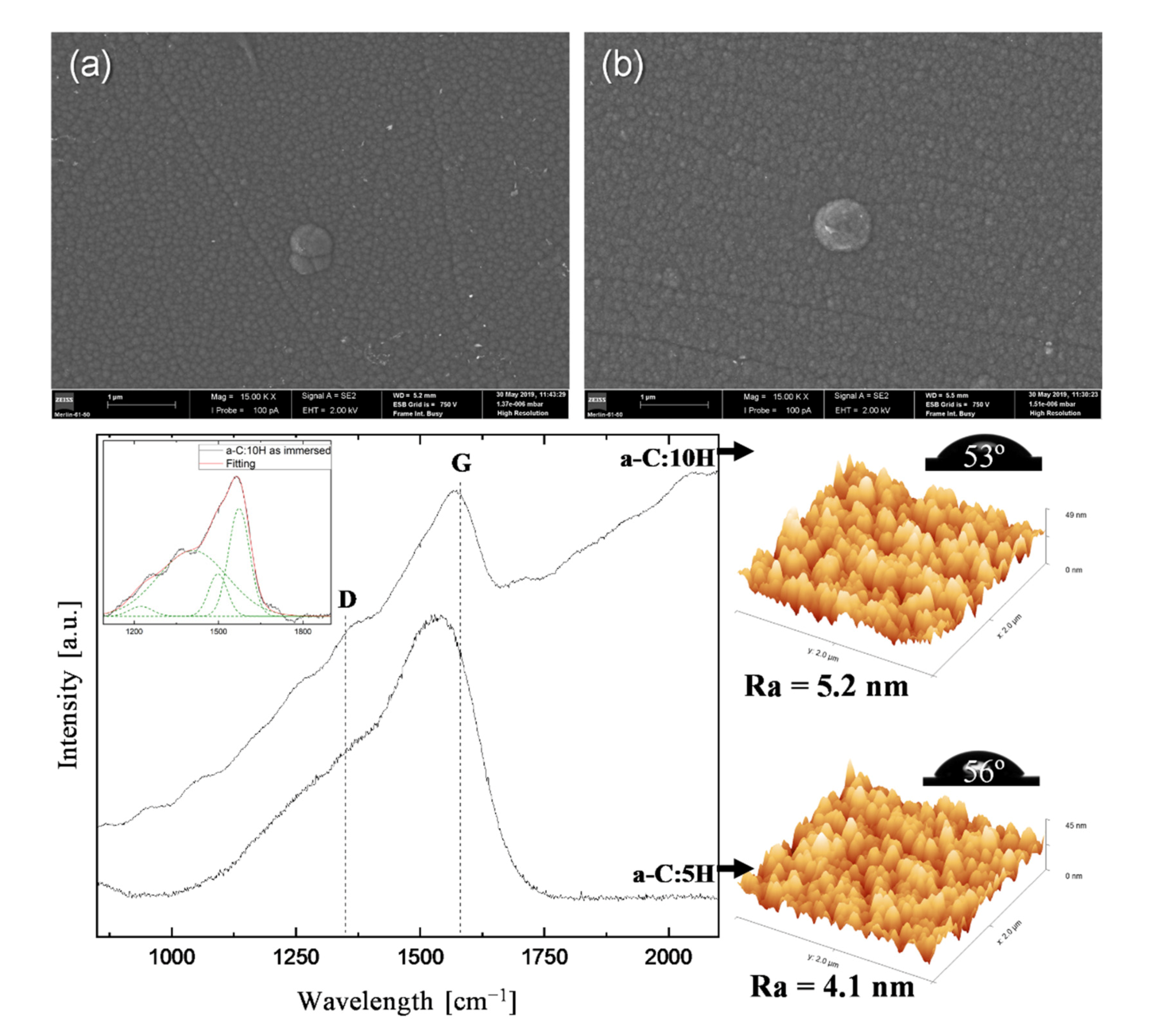
The results obtained show that both a-C:H coatings are new promising surface materials in orthodontics. In fact, the comparison between the as-deposited and as-immersed conditions, Table 2, validates the expected inertness behavior of the C-based coatings. No appreciable microstructural or mechanical variations were detected, without any signs of corrosion, delamination, or coating detachment from the substrates. As seen in Figure 3a,b, surface morphologies are very similar to those observed before immersion, Figure 1, and the conic defects remained after 30 days in acid artificial saliva.
Note, however, that contact angle values decreased, Figure 3, and are now below Berg’s limit [59,60], confirming the hydrophilic nature of the coatings produced in this study. Since the decreases are similar (~14 and 13°) for both coatings, the most likely cause is an analogous effect of the artificial saliva on either surface. Element adsorption from the solution, which persisted after cleaning procedures prior to analysis, may have influenced surface wettability. The surface roughness, Ra, remains low for both coatings, less than 6 nm.
Raman analysis revealed that structural binding of the a-C:H coatings was unaffected after the 30-day immersion test in aggressive acidic saliva solution, and their distinct DLCH and GLCHH characteristics are conserved. In fact, as-deposited and as-immersed spectra of both coatings are almost coincident (Figure 2 and Figure 3), with no observable changes in the G and D peak positions or sp3 content (Table 2). Mechanical behavior after acidic immersion was also preserved in the hard (~18 GPa) and soft (~7 GPa) regimes, according to the structural and chemical characteristics.
Such encouraging results indicate that a-C:H protective coatings should rise as promising candidates to help solve the corrosion issue in orthodontics. However, unfortunately, the ICP-OES data, due to their protective ability, were clearly beyond expectations (Figure 4). It is well known that the general corrosion mechanisms and the subsequent metal release from SS samples involves the loss of the passive character of the chromium oxide and/or chromium hydroxide layer. Nevertheless, SS316L is considered to have excellent corrosion resistance, and the low Ni, Cr, and Fe ion release rates obtained confirm this property. However, data show that a-C:H-coated samples released considerably higher amounts of ions during the 30-day immersion test than the reference sample, Figure 4, while the opposite was logically anticipated.
These findings are difficult to explain, since half of each SS316L coated substrate was covered with an inert, stable a-C:H layer (as confirmed by the characterization performed and presented above). In fact, a recent study [64] focusing on the characterization of the electrochemical stability of DLC coated interlayers and interfaces highlights the crucial role of metallic-based interlayers in increasing overall corrosion susceptibility, due to the formation of galvanic cells, particularly if Cr–C based interlayers are used. Indeed, most authors that found a significant in vitro decrease in metal release from DLC-coated samples (for instance, in artificial saliva [65] and saline [66]) did not report the use of interlayers. Ongoing studies focus on avoiding a Cr-based interlayer and replacing it with other materials.
Despite the obvious higher metal ion release from a-C:H-coated samples when compared with uncoated SS316L, Figure 4, it is necessary to notice that the values found are considered non-toxic: dietary studies conducted in different countries estimated a daily intake of Ni from food and drinking water of 100–300 μg/day (and consumption of Ni-enriched foodstuff may increase this value up to 900 μg/day [22,67]). Concerning Cr, an average daily intake of 280 μg/day was estimated [22]. Finally, Fe is an essential element and is consumed daily in large quantities in the human diet, including in drinking water, and does not represent a risk to human health [68,69].

3.3. Biological Characterization: In Vitro Citotoxicity

The MTT cellular viability values for fibroblasts, macrophages, and their co-culture, regarding cytotoxicity due to incubation (3 and 5 days) with the extracts, are presented in Figure 5. Two rows of control wells per culture plate have been seeded, i.e., only cells with medium fibroblasts, macrophages, or their co-culture, respectively.

3.3.1. Fibroblasts

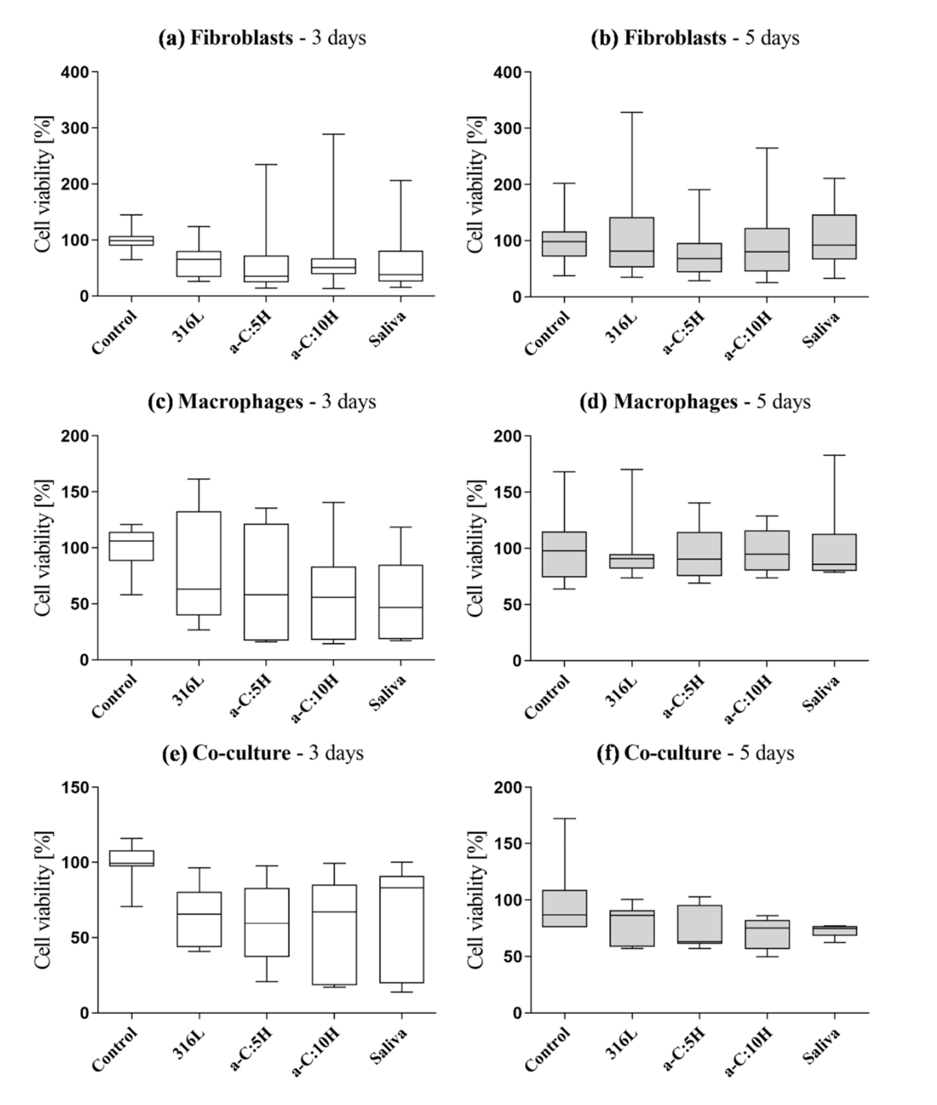
Statistical analysis of fibroblast results after 3 days of incubation revealed statistically significant differences (p < 0.001) between the five study groups (Control, SS316L, a-C:5H, a-C:10H and Saliva) due to the following pairs: Control-SS316L (p = 0.001), Control-a-C:5H (p < 0.001), Control-a-C:10H (p < 0.001) and Control-Saliva (p < 0.001).
The statistical differences between the control and the extracts may be due to their chemical compositions, since ICP-OES analysis detected the presence of Ni, Cr, and Fe (Figure 4). The cytotoxic and carcinogenic effect of Ni is well-established in the literature. In fact, studies conducted by Terpilowska et al. [70] and Taira et al. [71] verified that this element reduced cellular viability of several types of fibroblasts. As for Cr, its cytotoxic effect and ability to induce DNA mutations and oxidative stress in cell cultures were also reported in the literature [72,73]. According to the graph of Figure 5a, the coated metallic samples (a-C:5H and a-C:10H) incubated with extracts showed lower cellular viability than the ones for only-polished reference samples (SS316L), which was not expected. However, these findings agree with the ICP-OES values, since uncoated SS316L samples revealed lower Ni and Cr concentration values in the artificial saliva solution.
Statistically significant differences between Control and Saliva may be justified due to the low pH value of the saliva. Borsi et al. [74] reported a significant reduction in fibroblast proliferation for pH values below 7.0. In addition, Kruse et al. [75] indicated that fibroblast proliferation is reduced for a pH value under 6.5, and cellular viability decreases in acidic environments. The low pH value of the artificial saliva was easily confirmed by the phenol red present in the culture medium (DMEM): the “pink-colored” medium (pH 7.4) became “orange” immediately after adding the extract drops.
After 5 days of incubation, fibroblasts showed statistically significant differences (p = 0.004) regarding Control-a-C:5H (p = 0.013) and Saliva-a-C:5H (p = 0.020). With a longer incubation period, statistically significant differences in Control-SS316L, Control-a-C:10H, and Control-Saliva disappeared, realizing that cells had more time to release growth factors. Associated with intrinsic cellular defense mechanisms, these factors allowed a better adaptation of the fibroblasts to the medium conditioned with Cr and Ni ions. Moreover, fibroblasts, after 3 days of incubation, are still in an early growing stage; therefore, any added stimuli into the culture medium will affect their viability. However, statistically significant differences in Control-a-C:5H remain, as well as in Saliva and a-C:5H, which did not appear after 3 days. From the analysis of Figure 5b, it is possible to verify that values for Control and Saliva are similar, i.e., values of cellular viability for both media are statistically identical (p = 0.906).
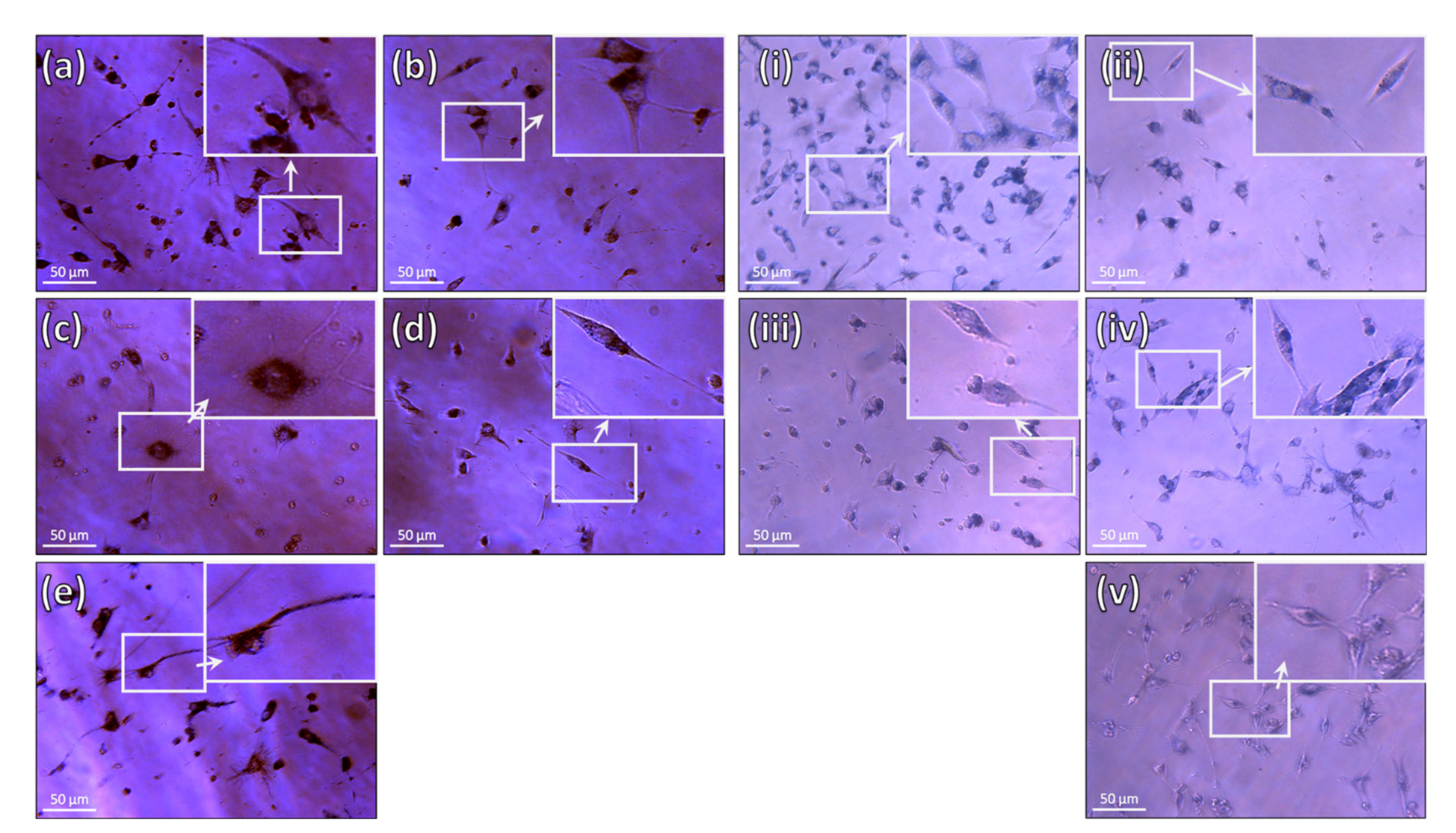
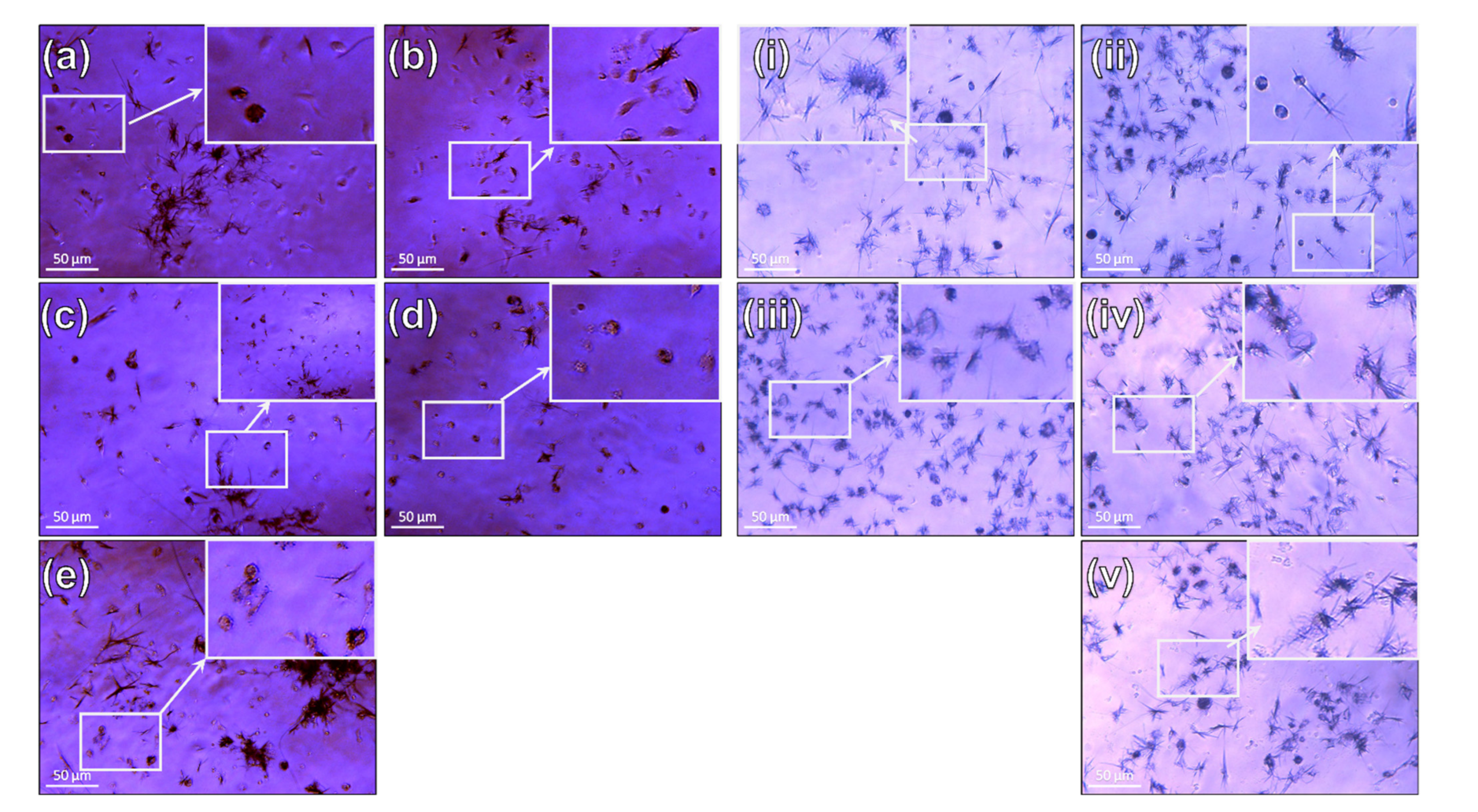
After the MTT test, the OPCM micrographs of fibroblasts (Figure 6a–e) provided further insights. After 3 days of incubation, Control fibroblasts showed a more elongated and flatter morphology, which is typical of further developed fibroblasts (Figure 6a). As they continue to multiply themselves, there are also a few round-shaped, more tridimensional fibroblasts present, i.e., characteristic of cells in an earlier stage of development. Fibroblasts with this round-shape morphology are present in higher numbers in wells conditioned with extracts (Figure 6b–d). Additionally, an expressively lower total number of cells is observed when compared with the Control, confirming the statistical analysis. This decrease is also perceived for Saliva samples (Figure 6e), yet not so expressive.
After 5 days of incubation, both the number and morphology of these cells show some differences (Figure 6i–v). In the Control (Figure 6i), there is a much higher number of fibroblasts, showing a more elongated, branched, and flatter morphology, suggesting a more developed growing stage. In medium conditioned with extracts from SS316L (Figure 6ii), the number of cells is lower when compared with the Control, but higher in comparison with the 3-day homologous wells (Figure 6b). Furthermore, these fibroblasts are in a more advanced development stage (fibrocytes). An identical feature is observed for a-C:10H and Saliva samples (Figure 6iv,v), only exhibiting a higher number of fibroblasts than the groups conditioned by extracts from SS316L. In the a-C:5H group, however, the presence of fewer fibroblasts is notorious (Figure 6iii). Moreover, most of these cells are still in an early growth stage (round-shaped, more tridimensional), revealing development/adhesion difficulties. This observation confirms the statistical analysis and other results: metallic ions present in the a-C:5H extracts inhibit the usual growth and proliferation of fibroblasts.

3.3.2. Macrophages

In contrast to fibroblasts, statistical analysis of macrophage cellular viability revealed no statistically significant differences between the groups after 3 and 5 days of incubation (p = 0.110 and 0.991, respectively). These p-values allowed us to conclude that the presence of artificial saliva or the released products from coated or uncoated samples induced no severe effects on the cellular viability of macrophages, which are phagocytic cells.
Despite the absence of significant variations, the decrease in cellular viability is noteworthy (Figure 5c). As for fibroblast culture, extracts from coated and uncoated metallic samples (SS316L, a-C:5H and a-C:10H) induced variations in cellular viability due to Ni and Cr release after 3 days. Once more, a-C:5H and a-C:10H showed lower values than SS316L. Cellular viability values are also lower in Saliva due to the acidic pH of saliva.
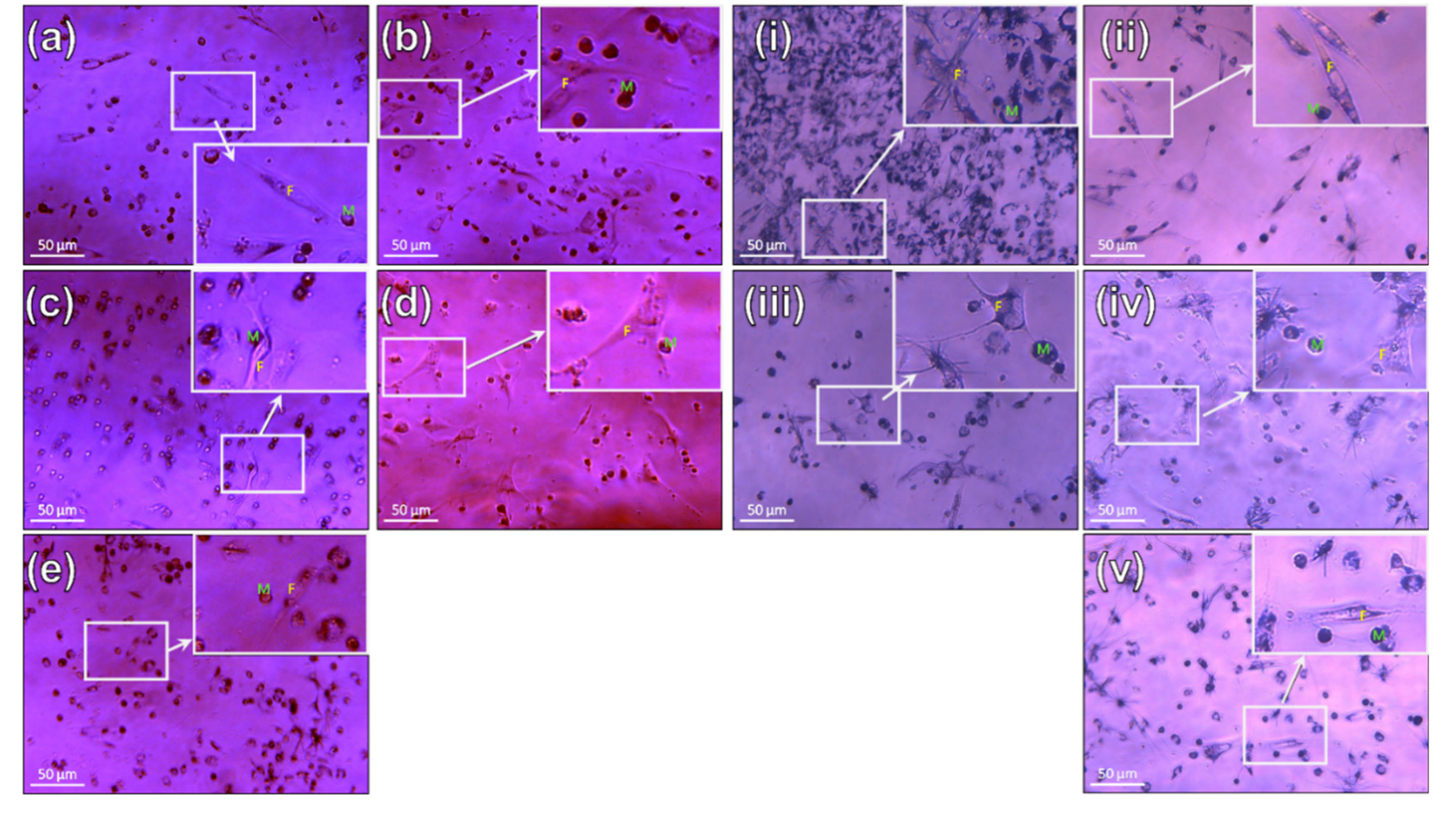
For all groups, OPCM micrographs revealed a decrease in the cell number in comparison with the Control. Macrophages displayed their typical rounded shape with some projections (Figure 7a–e). When the medium is conditioned with the extracts (Figure 7b–d), the round shape was maintained; however, the cells were bigger. In Saliva sample (Figure 7e), a slight reduction in the cell number was observed due to the low pH, but their dimensions and shapes were identical to the Control, frequently displaying filopodia-like projections.
After 5 days of incubation (Figure 5d), the obtained results were also similar between groups, but higher when compared with the 3-day test. Like fibroblasts, macrophages adapted themselves to the four media, even when conditioned with the extracts from a-C:5H. Macrophages have the ability of phagocyting released ions that are present in the extracts, converting the media into an adequate environment for their survival and leading to a positive cellular response. Cellular viability variations are due to the natural death of the naive macrophages, since these cells do to divide in vitro.
When compared with the 3-day test, OPCM micrographs after 5 days showed that these cells maintained their rounded-shape morphology with slightly bigger dimensions than the Control (Figure 7ii–iv) when seeded in contact with extracts (SS316L, a-C:5H and a-C:10H). This finding agrees with previous results, i.e., macrophages phagocyted the released products from coated and uncoated SS samples and had more phagocytic vesicles inside. Finally, macrophages seeded in Saliva displayed similar characteristics to the Control, demonstrating their adaptability to the acidic medium along time.

3.3.3. Co-Culture (Fibroblasts and Macrophages)

When fibroblasts and macrophages were co-incubated for 3 days (Figure 5e), statistically significant differences (p = 0.04) were obtained between Control-SS316L (p = 0.034), Control-a-C:5H (p = 0.010), Control-a-C:10H (p = 0.009), and Control-Saliva (p =0.049). These findings indicate once again that the extracts from uncoated SS316L, and a-C:5H and a-C:10H coatings, as well as the low pH value from the artificial saliva, induced an effect on the cellular viability of the co-culture. Interestingly, these results are similar to those from the fibroblast monoculture test. For the5-day incubation test, however, no statistically significant differences were observed, showing an adaptability of cells to all conditioned media (Figure 5f).
When compared with the Control, 3-day OPCM micrographs of the other groups revealed that the number of macrophages continued to be higher than the number of fibroblasts (Figure 8a–e). In general, macrophages showed their round-shape, tridimensional morphologies, and fibroblasts had a more tridimensional elongated shape. Still, some of the latter were flatter. Regarding a-C:10H group (Figure 8d), fibroblasts were, in fact, flat and elongated, being notoriously fewer in number, justifying the low p value (p = 0.009). Finally, the Saliva group showed similar results to the Control, with an abundant number of fibroblasts among macrophages. Since macrophage monoseeding did not reveal statistically significant differences, it is possible to conclude that the obtained results for the co-culture tests may be due to the response of fibroblasts to the extracts and artificial saliva. Under the study conditions, this adaptation occurred due to the high number of macrophages in the co-culture when compared with fibroblasts: a proportion of 20 macrophages per fibroblast (keep in mind that naive macrophages do not divide in vitro). Macrophages phagocyted the products released by coated and uncoated metallic samples, consequently improving the media for the survival and proliferation of fibroblasts. From the study results, it is possible to conclude that this is valid for all tested groups, including for a-C:5H. Only the 5-day test with fibroblast monoculture for a-C:5H continued to reveal statistically significant differences when compared with the Control. Furthermore, macrophages aided in the neutralization of the effects of the low pH value of the artificial Saliva.
It should be noted that the macrophage:fibroblast ratio used (20:1) represents an extreme scenario. However, this is quite common in orthodontic patients since they are more susceptible to the onset lesions of the oral mucosa due to the presence of the orthodontic appliances and the maintenance procedures performed by the dentist. Therefore, a higher number of macrophages may be present in their oral mucosa [76,77].
OPCM micrographs of the 5-day co-culture test revealed a higher number of macrophages compared to fibroblasts in the Control, occupying almost the entire surface (Figure 8i). These cells presented higher dimensions when compared with the ones of the 3-day controls (Figure 8a), due to the growth factors released by fibroblasts during the incubation period. In the other groups, a reduction of the number of cells was observed regarding the Control (Figure 8ii–iv). Some macrophages had larger dimensions than the respective 3-day homologous groups. This occurred due to the phagocytotic process of the released products present in the extracts. In addition, some elongated flat fibroblasts were seen, particularly in the media conditioned with artificial saliva (Figure 8v), and extracts from SS316L (Figure 8ii).
According to the ISO 10993-5 [43], the results of the 3-day incubation tests for extracts revealed that the coatings are somewhat cytotoxic for both cell types, since cellular viabilities decreased more than 30%. However, these reductions were not observed after 5 days of incubation. Along time, macrophages helped fibroblasts to adapt to the environment since they phagocyted possible intercurrent substances/products, and fibroblasts also helped macrophages due to the release of growth factors. Both kinds of cells interacted and helped each other, as expected, leading to a mutual adaptation that made the coatings non-cytotoxic.
In order to draw definitive and more robust conclusions, on the cytotoxicity of the studied coatings regarding several mono- or co-cultured cell types, more replicates of each group should be done for other periods of time. For instance, a seven-day study should be carried out to evaluate whether cellular viability is maintained beyond 5 days. It is necessary to note that seven days is a long incubation period for naive macrophages since they do not divide it vitro. Specially if there is no aggression stimuli, such as in controls and artificial saliva groups, no important response is needed from these cells [78]. Nevertheless, seven days matches the beginning of the in vivo stabilization of the healing process and angiogenesis [79,80]. In the particularly complex environment of the oral cavity, sutures should be ideally removed between the 5th and the 15th day after surgery, according to the surgical procedure (e.g., exodontia, aesthetics) [81].
An ongoing study includes a seven-day co-culture incubation test with fibroblasts and macrophages. Macrophages should be able to prepare the environment for fibroblasts through phagocytosis of undesirable products released either by coated or uncoated samples, allowing their better development. On the other side, the production of growth factors by fibroblasts might increase the lifespan of macrophages.

4. Conclusions

Amorphous hydrogenated carbon structures by magnetron sputtering in two reactive CH4 atmospheres diluted in Ar (6% and 18%, respectively) were successfully deposited on SS316L, with a Cr-based adhesion-promoting interlayer.
Two different types of a-C:H coatings were found in the hard (18 GPa) and soft (7 GPa) regimes, included in the DLCH and GLCHH classification, respectively.
The acid Fusayama-Meyer artificial saliva immersion of 30 days did not influence the structural or mechanical behavior of the sputtered coatings, regardless the H content. No signs of corrosion, delamination, or coating detachment from the substrates were observed. However, leaching of metallic ions from coated samples into the artificial saliva was higher in comparison with the reference ones, due to the galvanic effects from the Cr-based interlayer. Such findings illustrate the crucial importance of the interface between metal substrate/coating system when C-based coatings are to be considered for orthodontic applications.
The cell viability with macrophages and fibroblasts, either in mono- or co-culture in extracts, was confirmed for both coatings. The highest biocompatibility was found for coatings with the lowest H content.
Considering that Ni-containing alloys will continue to be used in biomedical applications, this research contributes by reinforcing the fact that a-C:H coatings can extend their application range to orthodontics.
Ongoing studies focus on replacing the Cr-based interlayer with other types of materials and architectures, while extending both fibroblast monoculture and co-culture assay durations. Furthermore, in vitro microbiological assays with representative oral bacteria will soon be performed to understand their influence on the a-C:H coatings.

Author Contributions

Conceptualization, C.S.L. and A.C.S.; data curation, A.F. and A.S.A.; formal analysis, A.F. and A.S.A.; funding acquisition, A.F.; investigation, A.F., M.E., and A.S.A.; methodology, C.S.L. and A.C.S.; project administration, C.S.L. and A.C.S.; resources, C.S.L., A.C.S., and M.E.; supervision, C.S.L. and A.C.S.; validation, C.S.L., A.F., A.C.S., and A.S.A.; visualization, A.F. and A.S.A.; writing—original draft, A.F. and A.S.A.; writing—review and editing, C.S.L. and A.C.S. All authors have read and agreed to the published version of the manuscript.

Funding

This research is sponsored by national funds through FCT–Fundação para a Ciência e a Tecnologia, through PhD grant SFRH/BD/143905/2019 attributed to A.F.

Institutional Review Board Statement

Not applicable.

Informed Consent Statement

Not applicable.

Data Availability Statement

Not applicable.

Acknowledgments

This research is sponsored by national funds through FCT–Fundação para a Ciência e a Tecnologia, under the project UIDB/00285/2020.

Conflicts of Interest

The authors declare no conflict of interest.

References

  1. Proffit, W.R.; Fields, H.W.; Sarver, D.M.; Ackerman, J.L. Contemporary orthodontic appliances. In Contemporary Orthodontics; Mosby, Elsevier: Amsterdam, The Netherlands, 2012; pp. 347–389. ISBN 978032308317. [Google Scholar]
  2. Abdallah, M.-N.; Lou, T.; Retrouvey, J.-M.; Suri, S. Biomaterials used in orthodontics: Brackets, archwires, and clear aligners. In Advanced Dental Biomaterials; Khurshid, Z., Najeeb, S., Zafar, M.S., Sefat, F., Eds.; Elsevier: Amsterdam, The Netherlands, 2019; pp. 541–579. ISBN 978-0-08-102476-8. [Google Scholar]
  3. Mystkowska, J.; Niemirowicz-Laskowska, K.; Łysik, D.; Tokajuk, G.; Dąbrowski, J.R.; Bucki, R. The role of oral cavity biofilm on metallic biomaterial surface destruction–corrosion and friction aspects. Int. J. Mol. Sci. 2018, 19, 743. [Google Scholar] [CrossRef] [Green Version]
  4. Mosca, A.C.; Chen, J. Food-saliva interactions: Mechanisms and implications. Trends Food Sci. Technol. 2017, 66, 125–134. [Google Scholar] [CrossRef]
  5. Kwak, D.Y.; Kim, N.Y.; Kim, H.J.; Yang, S.Y.; Yoon, J.E.; Hyun, I.A.; Nam, S.H. Changes in the oral environment after tooth brushing and oral gargling. Biomed. Res. 2017, 28, 7093–7097. [Google Scholar]
  6. Moore, R.J.; Watts, J.T.F.; Hood, J.A.A.; Burritt, D.J. Intra-oral temperature variation over 24 hours. Eur. J. Orthod. 1999, 21, 249–261. [Google Scholar] [CrossRef] [PubMed] [Green Version]
  7. Marsh, P.D.; Head, D.A.; Devine, D.A. Dental plaque as a biofilm and a microbial community—Implications for treatment. J. Oral Biosci. 2015, 57, 185–191. [Google Scholar] [CrossRef]
  8. Chaturvedi, T.P.; Upadhayay, S.N. An overview of orthodontic material degradation in oral cavity. Indian J. Dent. Res. 2010, 21, 275–284. [Google Scholar] [CrossRef]
  9. Eliades, T.; Athanasiou, A.E. In Vivo Aging of orthodontic alloys: Implications for corrosion potential, nickel release, and biocompatibility. Angle Orthod. 2002, 72, 222–237. [Google Scholar]
  10. Frois, A.; Cunha, L.; Louro, C.S. Functionalization of Orthodontic Alloys with DLC Coatings. In Proceedings of the 2019 IEEE 6th Portuguese Meeting on Bioengineering (ENBENG), Lisbon, Portugal, 22–23 February 2019; IEEE: Lisbon, Portugal, 2019; pp. 1–4. [Google Scholar]
  11. Kao, C.-T.; Huang, T.-H. Variations in surface characteristics and corrosion behaviour of metal brackets and wires in different electrolyte solutions. Eur. J. Orthod. 2010, 32, 555–560. [Google Scholar] [CrossRef] [PubMed] [Green Version]
  12. Li, X.; Wang, J.; Han, E.; Ke, W. Influence of fluoride and chloride on corrosion behavior of NiTi orthodontic wires. Acta Biomater. 2007, 3, 807–815. [Google Scholar] [CrossRef]
  13. Daems, J.; Celis, J.-P.; Willems, G. Morphological characterization of as-received and in vivo orthodontic stainless steel archwires. Eur. J. Orthod. 2009, 31, 260–265. [Google Scholar] [CrossRef] [Green Version]
  14. Eliaz, N. Corrosion of Metallic Biomaterials: A Review. Materials 2019, 12, 407. [Google Scholar] [CrossRef] [Green Version]
  15. Martín-Cameán, A.; Jos, Á.; Mellado-García, P.; Iglesias-Linares, A.; Solano, E.; Cameán, A.M. In vitro and in vivo evidence of the cytotoxic and genotoxic effects of metal ions released by orthodontic appliances: A review. Environ. Toxicol. Pharmacol. 2015, 40, 86–113. [Google Scholar] [CrossRef]
  16. IARC (International Agency for Research on Cancer). Nickel and nickel compounds. IARC Monogr. Eval. Carcinog. Risks Hum. 2011, 100C, 169–218. [Google Scholar] [CrossRef]
  17. Saito, M.; Arakaki, R.; Yamada, A.; Tsunematsu, T.; Kudo, Y.; Ishimaru, N. Molecular mechanisms of nickel allergy. Int. J. Mol. Sci. 2016, 17, 202. [Google Scholar] [CrossRef] [Green Version]
  18. Dunlap, C.L.; Vincent, S.K.; Barker, B.F. Allergic reaction to orthodontic wire: Report of case. J. Am. Dent. Assoc. 1989, 118, 449–450. [Google Scholar] [CrossRef] [Green Version]
  19. Noble, J.; Ahing, S.I.; Karaiskos, N.E.; Wiltshire, W.A. Nickel allergy and orthodontics, a review and report of two cases. Br. Dent. J. 2008, 204, 297–300. [Google Scholar] [CrossRef]
  20. Kolokitha, O.E.; Chatzistavrou, E. A severe reaction to Ni-containing orthodontic appliances. Angle Orthod. 2009, 79, 186–192. [Google Scholar] [CrossRef] [PubMed] [Green Version]
  21. Ellis, P.E.; Benson, P.E. Potential hazards of orthodontic treatment—What your patient should know. Dent. Update 2002, 29, 492–496. [Google Scholar] [CrossRef] [PubMed] [Green Version]
  22. House, K.; Sernetz, F.; Dymock, D.; Sandy, J.R.; Ireland, A.J. Corrosion of orthodontic appliances-should we care? Am. J. Orthod. Dentofac. Orthop. 2008, 133, 584–592. [Google Scholar] [CrossRef] [PubMed]
  23. Russell, J.S. Current products and practice: Aesthetic orthodontic brackets. J. Orthod. 2005, 32, 146–163. [Google Scholar] [CrossRef]
  24. Arango, S.; Peláez-Vargas, A.; García, C. Coating and surface treatments on orthodontic metallic materials. Coatings 2013, 3, 1–15. [Google Scholar] [CrossRef]
  25. Robertson, J. Diamond-like amorphous carbon. Mater. Sci. Eng. R Rep. 2002, 37, 129–281. [Google Scholar] [CrossRef] [Green Version]
  26. Vetter, J. 60years of DLC coatings: Historical highlights and technical review of cathodic arc processes to synthesize various DLC types, and their evolution for industrial applications. Surf. Coat. Technol. 2014, 257, 213–240. [Google Scholar] [CrossRef]
  27. Zahid, R.; Masjuki, H.H.; Varman, M.; Kalam, M.A.; Mufti, R.A.; Zulkifli, N.W.B.M.; Gulzar, M.; Azman, S.S.B.N. Influence of intrinsic and extrinsic conditions on the tribological characteristics of diamond-like carbon coatings: A review. J. Mater. Res. 2016, 31, 1814–1836. [Google Scholar] [CrossRef]
  28. Ohgoe, Y.; Hirakuri, K.K.; Saitoh, H.; Nakahigashi, T.; Ohtake, N.; Hirata, A.; Kanda, K.; Hiratsuka, M.; Fukui, Y. Classification of DLC films in terms of biological response. Surf. Coat. Technol. 2012, 207, 350–354. [Google Scholar] [CrossRef]
  29. Casiraghi, C.; Ferrari, A.C.; Robertson, J. Raman spectroscopy of hydrogenated amorphous carbons. Phys. Rev. B 2005, 72, 085401. [Google Scholar] [CrossRef] [Green Version]
  30. Hauert, R.; Thorwarth, K.; Thorwarth, G. An overview on diamond-like carbon coatings in medical applications. Surf. Coat. Technol. 2013, 233, 119–130. [Google Scholar] [CrossRef]
  31. Love, C.A.; Cook, R.B.; Harvey, T.J.; Dearnley, P.A.; Wood, R.J.K. Diamond like carbon coatings for potential application in biological implants—A review. Tribol. Int. 2013, 63, 141–150. [Google Scholar] [CrossRef] [Green Version]
  32. Kang, T.; Huang, S.-Y.; Huang, J.-J.; Li, Q.-H.; Diao, D.-F.; Duan, Y.-Z. The effects of diamond-like carbon films on fretting wear behavior of orthodontic archwire-bracket contacts. J. Nanosci. Nanotechnol. 2015, 15, 4641–4647. [Google Scholar] [CrossRef] [PubMed]
  33. Muguruma, T.; Iijima, M.; Kawaguchi, M.; Mizoguchi, I. Effects of sp2/sp3 ratio and hydrogen content on in vitro bending and frictional performance of dlc-coated orthodontic stainless steels. Coatings 2018, 8, 199. [Google Scholar] [CrossRef] [Green Version]
  34. Akaike, S.; Kobayashi, D.; Aono, Y.; Hiratsuka, M.; Hirata, A.; Hayakawa, T.; Nakamura, Y. Relationship between static friction and surface wettability of orthodontic brackets coated with diamond-like carbon (DLC), fluorine- or silicone-doped DLC coatings. Diam. Relat. Mater. 2016, 61, 109–114. [Google Scholar] [CrossRef]
  35. Ferrari, A.C. Non-destructive characterisation of carbon films. In Tribology of Diamond-Like Carbon Films: Fundamentals and Applications; Donnet, C., Erdemir, A., Eds.; Springer: Berlin/Heidelberg, Germany, 2008; pp. 25–82. ISBN 9780387302645. [Google Scholar]
  36. Schwan, J.; Ulrich, S.; Batori, V.; Ehrhardt, H.; Silva, S.R.P. Raman spectroscopy on amorphous carbon films. J. Appl. Phys. 1996, 80, 440–447. [Google Scholar] [CrossRef] [Green Version]
  37. Singha, A.; Ghosh, A.; Roy, A.; Ray, N.R. Quantitative analysis of hydrogenated diamondlike carbon films by visible raman spectroscopy. J. Appl. Phys. 2006, 100, 044910. [Google Scholar] [CrossRef] [Green Version]
  38. ISO 10271:2001—Dental Metallic Materials—Corrosion Test Methods; ISO (International Organization for Standardization): Geneva, Switzerland, 2001.
  39. ATCC (American Type Culture Collection). NIH/3T3 (ATCC CRL-1658). Available online: https://www.atcc.org/products/crl-1658 (accessed on 21 November 2020).
  40. Rejmontová, P.; Capáková, Z.; Mikušová, N.; Maráková, N.; Kašpárková, V.; Lehocký, M.; Humpolíček, P. Adhesion, proliferation and migration of NIH/3T3 cells on modified polyaniline surfaces. Int. J. Mol. Sci. 2016, 17, 1439. [Google Scholar] [CrossRef] [Green Version]
  41. Xiao, W.; Su, Y.; Zhou, S.; Yi, C.; He, G.; Liu, Y.; Qi, Y. Rasgrp2 regulates the permissiveness of NIH3T3 cells to a herpes simplex virus 1 mutant with inactivated ICP34.5 gene. Acta Virol. 2013, 57, 41–49. [Google Scholar] [CrossRef] [Green Version]
  42. Santos, A.C.A. Água Trocável do Pulmão: Contribuição para o Desenvolvimento de uma Metodologia para a sua Avaliação; Universidade de Coimbra: Coimbra, Portugal, 2001. [Google Scholar]
  43. ISO 10993-5:2009 Biological Evaluation of Medical Devices—Part 5: Tests for In Vitro Cytotoxicity; ISO (International Organization for Standardization): Geneva, Switzerland, 2009.
  44. Costa, M.T.; Lenza, M.A.; Gosch, C.S.; Costa, I.; Ribeiro-Dias, F. In vitro evaluation of corrosion and cytotoxicity of orthodontic brackets. J. Dent. Res. 2007, 86, 441–445. [Google Scholar] [CrossRef]
  45. Riss, T.L.; Moravec, R.A.; Niles, A.L.; Duellman, S.; Benink, H.A.; Worzella, T.J.; Minor, L. Cell Viability Assays. In Assay Guidance Manual; Sittampalam, G.S., Grossman, A., Brimacombe, K., Arkin, M., Auld, D., Austin, C.P., Baell, J., Bejcek, B., Caaveiro, J.M.M., Chung, T.D.Y., et al., Eds.; Eli Lilly & Company and the National Center for Advancing Translational Sciences: Bethesda, MD, USA, 2013; pp. 295–320. [Google Scholar]
  46. Louro, C.; Moura, C.W.; Carvalho, N.; Stueber, M.; Cavaleiro, A. Thermal stability in oxidative and protective environments of a-C:H cap layer on a functional gradient coating. Diam. Relat. Mater. 2011, 20, 57–63. [Google Scholar] [CrossRef] [Green Version]
  47. Chowdhury, S.; Laugier, M.T.; Rahman, I.Z. Characterization of DLC coatings deposited by rf magnetron sputtering. J. Mater. Process. Technol. 2004, 153–154, 804–810. [Google Scholar] [CrossRef]
  48. Lin, J.; Zhang, X.; Lee, P.; Wei, R. Thick diamond like carbon coatings deposited by deep oscillation magnetron sputtering. Surf. Coat. Technol. 2017, 315, 294–302. [Google Scholar] [CrossRef]
  49. Hatem, A.; Lin, J.; Wei, R.; Torres, R.D.; Laurindo, C.; Soares, P. Tribocorrosion behavior of DLC-coated Ti-6Al-4V alloy deposited by PIID and PEMS + PIID techniques for biomedical applications. Surf. Coat. Technol. 2017, 332, 223–232. [Google Scholar] [CrossRef]
  50. Keunecke, M.; Weigel, K.; Bewilogua, K.; Cremer, R.; Fuss, H.-G. Preparation and comparison of a-C:H coatings using reactive sputter techniques. Thin Solid Films 2009, 518, 1465–1469. [Google Scholar] [CrossRef]
  51. Drescher, D.; Koskinen, J.; Scheibe, H.J.; Mensch, A. A model for particle growth in arc deposited amorphous carbon films. Diam. Relat. Mater. 1998, 7, 1375–1380. [Google Scholar] [CrossRef]
  52. Dalibón, E.L.; Escalada, L.; Simison, S.; Forsich, C.; Heim, D.; Brühl, S.P. Mechanical and corrosion behavior of thick and soft DLC coatings. Surf. Coat. Technol. 2017, 312, 101–109. [Google Scholar] [CrossRef]
  53. Marchon, B.; Jing, G.; Grannen, K.; Rauch, G.C.; Ager, J.W.; Silva, S.R.P.; Robertson, J. Photoluminescence and Raman spectroscopy in hydrogenated carbon films. IEEE Trans. Magn. 1997, 33, 3148–3150. [Google Scholar] [CrossRef] [Green Version]
  54. Zhang, L.; Wei, X.; Lin, Y.; Wang, F. A ternary phase diagram for amorphous carbon. Carbon N. Y. 2015, 94, 202–213. [Google Scholar] [CrossRef]
  55. Sun, L.; Guo, P.; Li, X.; Wang, A. Comparative study on structure and wetting properties of diamond-like carbon films by W and Cu doping. Diam. Relat. Mater. 2017, 73, 278–284. [Google Scholar] [CrossRef]
  56. Gotzmann, G.; Beckmann, J.; Wetzel, C.; Scholz, B.; Herrmann, U.; Neunzehn, J. Electron-beam modification of DLC coatings for biomedical applications. Surf. Coat. Technol. 2017, 311, 248–256. [Google Scholar] [CrossRef]
  57. Ishige, H.; Akaike, S.; Hayakawa, T.; Hiratsuka, M.; Nakamura, Y. Evaluation of protein adsorption to diamond-like carbon (DLC) and fluorinedoped DLC films using the quartz crystal microbalance method. Dent. Mater. J. 2019, 38, 424–429. [Google Scholar] [CrossRef] [PubMed] [Green Version]
  58. Chen, J.S.; Lau, S.P.; Sun, Z.; Chen, G.Y.; Li, Y.J.; Tay, B.K.; Chai, J.W. Metal-containing amorphous carbon films for hydrophobic application. Thin Solid Films 2001, 398–399, 110–115. [Google Scholar] [CrossRef]
  59. Escudeiro, A.; Polcar, T.; Cavaleiro, A. Adsorption of bovine serum albumin on Zr co-sputtered a-C(:H) films: Implication on wear behaviour. J. Mech. Behav. Biomed. Mater. 2014, 39, 316–327. [Google Scholar] [CrossRef] [Green Version]
  60. Berg, J.M.; Eriksson, L.G.T.; Claesson, P.M.; Borve, K.G.N. Three-component langmuir-blodgett films with a controllable degree of polarity. Langmuir 1994, 10, 1225–1234. [Google Scholar] [CrossRef]
  61. Wenzel, R.N. Resistance of solid surfaces to wetting by water. Ind. Eng. Chem. 1936, 28, 988–994. [Google Scholar] [CrossRef]
  62. Ryan, B.J.; Poduska, K.M. Roughness effects on contact angle measurements. Am. J. Phys. 2008, 76, 1074–1077. [Google Scholar] [CrossRef] [Green Version]
  63. Hans, R.; Thomas, S.; Garla, B.; Dagli, R.J.; Hans, M.K. Effect of various sugary beverages on salivary ph, flow rate, and oral clearance rate amongst adults. Scientifica 2016, 2016. [Google Scholar] [CrossRef] [PubMed] [Green Version]
  64. Ilic, E.; Pardo, A.; Suter, T.; Mischler, S.; Schmutz, P.; Hauert, R. A methodology for characterizing the electrochemical stability of DLC coated interlayers and interfaces. Surf. Coat. Technol. 2019, 375, 402–413. [Google Scholar] [CrossRef]
  65. Kobayashi, S.; Ohgoe, Y.; Ozeki, K.; Hirakuri, K.; Aoki, H. Dissolution effect and cytotoxicity of diamond-like carbon coatings on orthodontic archwires. J. Mater. Sci. Mater. Med. 2007, 18, 2263–2268. [Google Scholar] [CrossRef]
  66. Ohgoe, Y.; Kobayashi, S.; Ozeki, K.; Aoki, H.; Nakamori, H.; Hirakuri, K.K.; Miyashita, O. Reduction effect of nickel ion release on a diamond-like carbon film coated onto an orthodontic archwire. Thin Solid Films 2006, 497, 218–222. [Google Scholar] [CrossRef]
  67. Cempel, M.; Nikel, G. Nickel: A review of its sources and environmental toxicology. Pol. J. Environ. Stud. 2006, 15, 375–382. [Google Scholar]
  68. De Souza, R.M.; De Menezes, L.M. Nickel, chromium and iron levels in the saliva of patients with simulated fixed orthodontic appliances. Angle Orthod. 2008, 78, 345–350. [Google Scholar] [CrossRef]
  69. WHO (World Health Organization). Guidelines for Drinking-Water Quality, 4th ed.; World Health Organization: Geneva, Switzerland, 2011. [Google Scholar]
  70. Terpiłowska, S.; Siwicka-Gieroba, D.; Krzysztof Siwicki, A. Cell viability in normal fibroblasts and liver cancer cells after treatment with iron (III), nickel (II), and their mixture. J. Vet. Res. 2018, 62, 535–542. [Google Scholar] [CrossRef] [Green Version]
  71. Taira, M.; Toguchi, M.S.; Hamada, Y.; Takahashi, J.; Itou, R.; Toyosawa, S.; Ijyuin, N.; Okazaki, M. Studies on cytotoxic effect of nickel ions on three cultured fibroblasts. J. Mater. Sci. Mater. Med. 2001, 12, 373–376. [Google Scholar] [CrossRef] [PubMed]
  72. Wang, Y.; Su, H.; Gu, Y.; Song, X.; Zhao, J. Carcinogenicity of chromium and chemoprevention: A brief update. OncoTargets Ther. 2017, 10, 4065–4079. [Google Scholar] [CrossRef] [PubMed] [Green Version]
  73. Shrivastava, H.Y.; Ravikumar, T.; Shanmugasundaram, N.; Babu, M.; Unni Nair, B. Cytotoxicity studies of chromium(III) complexes on human dermal fibroblasts. Free Radic. Biol. Med. 2005, 38, 58–69. [Google Scholar] [CrossRef] [PubMed]
  74. Borsi, L.; Allemanni, G.; Gaggero, B.; Zardi, L. Extracellular pH controls pre-mRNA alternative splicing of tenascin-C in normal, but not in malignantly transformed, cells. Int. J. Cancer 1996, 66, 632–635. [Google Scholar] [CrossRef]
  75. Kruse, C.R.; Singh, M.; Targosinski, S.; Sinha, I.; Sørensen, J.A.; Eriksson, E.; Nuutila, K. The effect of pH on cell viability, cell migration, cell proliferation, wound closure, and wound reepithelialization: In vitro and in vivo study. Wound Repair Regen. 2017, 25, 260–269. [Google Scholar] [CrossRef]
  76. Hasturk, H.; Kantarci, A.; Van Dyke, T.E. Oral Inflammatory Diseases and Systemic Inflammation: Role of the Macrophage. Front. Immunol. 2012, 3, 118. [Google Scholar] [CrossRef] [Green Version]
  77. Pereira, T.; Naik, S.; Tamgadge, A. Quantitative evaluation of macrophage expression using CD68 in oral submucous fibrosis: An immunohistochemical study. Ann. Med. Health Sci. Res. 2015, 5, 435. [Google Scholar] [CrossRef] [Green Version]
  78. Mendes, M. Métodos de Esterilização versus Adesão Celular para Scaffolds Numa Aplicação em Medicina Dentária; Universidade de Coimbra: Coimbra, Portugal, 2017. [Google Scholar]
  79. Johnson, K.E.; Wilgus, T.A. Vascular endothelial growth factor and angiogenesis in the regulation of cutaneous wound repair. Adv. Wound Care 2014, 3, 647–661. [Google Scholar] [CrossRef] [Green Version]
  80. Long, G.; Liu, D.; He, X.; Shen, Y.; Zhao, Y.; Hou, X.; Chen, B.; OuYang, W.; Dai, J.; Li, X.; et al. A dual functional collagen scaffold coordinates angiogenesis and inflammation for diabetic wound healing. Biomater. Sci. 2020, 8, 6337–6349. [Google Scholar] [CrossRef]
  81. Guimarães, J. Princípios de sutura na cavidade oral. Maxillaris 2012, 43, 28–34. [Google Scholar]
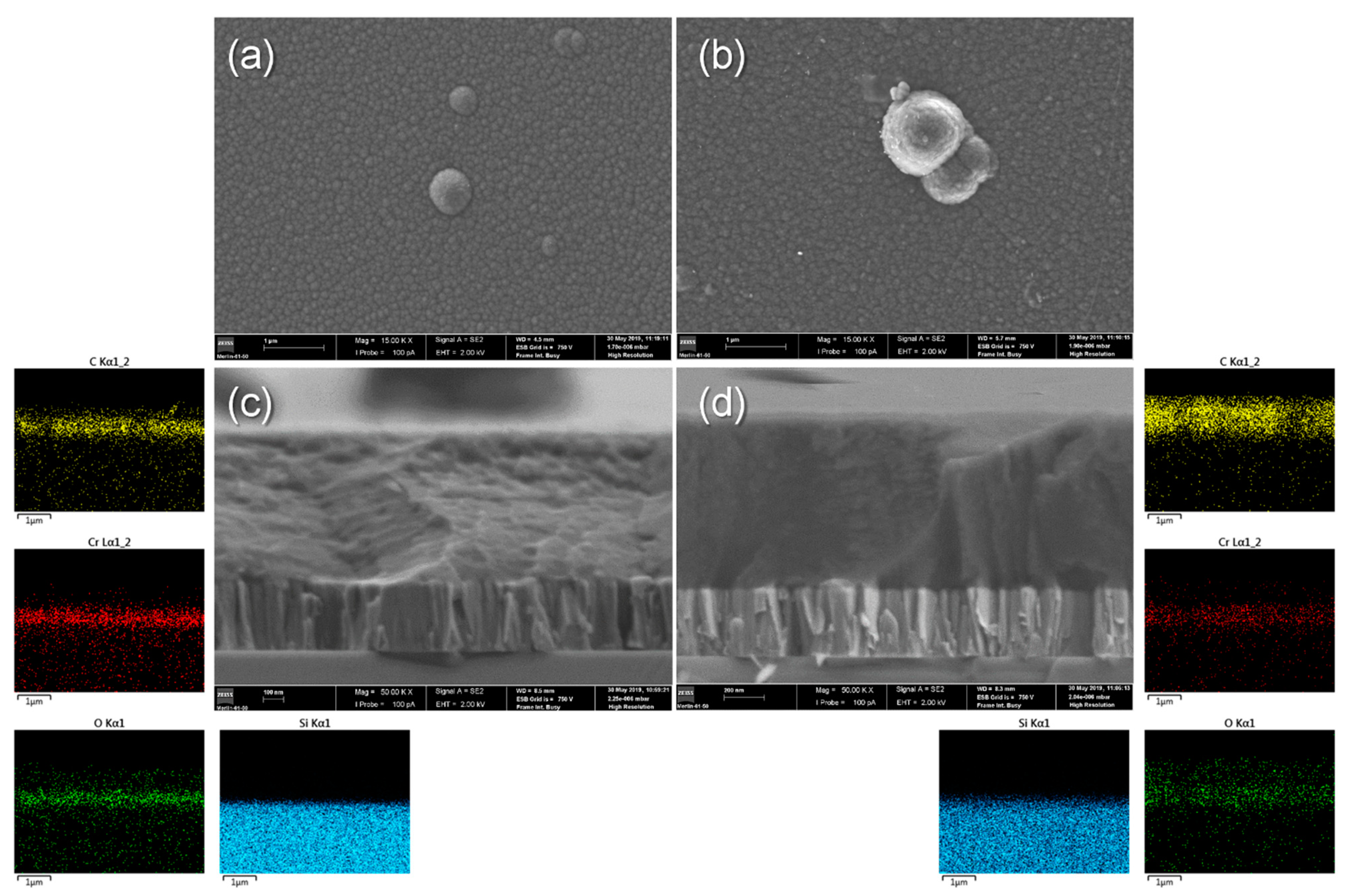
Figure 1. Surface and cross-section SEM micrographs of the as-deposited a-C:H coatings with Cr-based interlayer onto Si wafers, and the corresponding EDS elemental distribution maps: (a,c) for a-C:5H coatings; (b,d) for a-C:10H coatings.
Coatings 11 00832 g001
Figure 2. Visible Raman spectra of the as-deposited a-C:H coatings (inset: Gaussian fitting procedure for a-C:5H films), and the corresponding AFM surface topography and drop contact angles.
Coatings 11 00832 g002
Figure 3. Surface SEM micrographs of the as-immersed (a) a-C:5H and (b) a-C:10H coatings, and the corresponding visible Raman spectra (inset: Gaussian fitting procedure for a-C:10H films), AFM surface topography, and drop contact angles.
Coatings 11 00832 g003
Figure 4. Metal release rates of the uncoated and coated (a-C:5H and a-C:10H) SS316L samples during 30 days of immersion.
Coatings 11 00832 g004
Figure 5. MTT cell viability of (a,b) fibroblasts, (c,d) macrophages, or (e,f) co-culture after incubation with extracts for 3 and 5 days. Legend: 316L–medium conditioned with extracts from SS316L; a-C:5H–medium conditioned with extracts from a-C:5H coatings; a-C:10H–medium conditioned with extracts from a-C:10H coatings; Saliva–medium conditioned with extracts from artificial saliva. (MTT values are expressed in percentage of each mean value of each experimental Control.)
Coatings 11 00832 g005
Figure 6. Fibroblasts post-MTT observed with OPCM at 3 days (ae) and 5 days (iv) of incubation (200×): (a,i) control; (b,ii) conditioned medium with AISI 316L steel eluates; (c,iii) conditioned medium with a-C:5H coating eluates; (d,iv) conditioned medium with a-C:10H coating eluates; (e,v) conditioned medium with artificial saliva.
Coatings 11 00832 g006
Figure 7. Macrophages post-MTT observed with OPCM at 3 days (ae) and 5 days (iv) of incubation (200×): (a,i) control; (b,ii) conditioned medium with AISI 316L steel eluates; (c,iii) conditioned medium with a-C:5H coating eluates; (d,iv) conditioned medium with a-C:10H coating eluates; (e,v) conditioned medium with artificial saliva.
Coatings 11 00832 g007
Figure 8. Macrophage and fibroblast co-culture post-MTT observed with OPCM at 3 days (ae) and 5 days (iv) of incubation (200×): (a,i) control; (b,ii) conditioned medium with AISI 316L steel eluates; (c,iii) conditioned medium with a-C:5H coating eluates; (d,iv) conditioned medium with a-C:10H coating eluates; (e,v) conditioned medium with artificial saliva.
Coatings 11 00832 g008
Table 1. Chemical composition of the Fusayama-Meyer artificial saliva.
Concentration [g/L]
NaClKClCaCl2·2H2ONaH2PO4Na2S∙9H2OCO(NH2)2HCl (1 M)
0.40.40.7950.780.0051until pH = 2.3
Table 2. Main characteristics of the a-C:H coatings in both as-deposited and as-immersed conditions.
---a-C:5Ha-C:10H
As-dep.As-imm.As-dep.As-imm.
Flow gas ratioCH4:Ar1:91:5
Thickness [nm]Cr-based interlayera-C:H external layer343
743
313
849
Elemental composition * [at.%]C
Cr
O
Ar
95.2
2.8
0.4
1.6
94.6
3.1
0.5
1.8
91.3
2.0
6.7
0.0
91.5
2.1
6.4
0.0
Roughness [nm]Ra4.34.15.45.2
Contac Angle [°] 70 ± 156 ± 266 ± 153 ± 2
Nanohardness [GPa]HB18.2 ± 1.818.1 ± 1.27.1 ± 0.37.0 ± 0.5
Raman bonding configurationG band [cm−1]
ID/IG ratio
sp3 bonds [%]
1547
0.67
39.9
1547
0.65
40.2
1573
0.59
27.5
1573
0.61
27.3
Empirical H content [at. %] 28.0 ± 1.928.1 ± 1.339.9 ± 0.340.0 ± 0.5
* Chemical composition excluding H content.
Publisher’s Note: MDPI stays neutral with regard to jurisdictional claims in published maps and institutional affiliations.