1. Introduction
In the semiconductor manufacturing industry, three-dimensional integrated circuits (3D ICs) with vertically stacked integrated circuit chips have been developed and widely used in NAND flash memory, called 3D V-NAND [
1]. In scaling 3D V-NAND, the dry etching process has been advanced to create complex 3D structures with very high aspect ratio (HAR) features. In order to stack circuits in multi-layers, dry etching and cleaning processes are repeated many times in the semiconductor process chamber. Fluorocarbon etch gases such as C
4F
8, CHF
3, and C
3F
7OCH
3 are generally used for the plasma etching of silicon dioxide (SiO
2) and silicon nitride (Si
3N
4) [
2]. In extreme HAR plasma etch steps with those corrosive etching gases, the inner wall and other parts in the chamber were exposed to the high-power plasma and high temperature process for a long time, making them susceptible to plasma erosion and causing particles to be generated that act as contaminants [
3,
4].
Previously, the inner wall and parts in the etching chamber were spray-coated by yttrium oxide (Y
2O
3) for the protection from aggressive plasma. Since Y
2O
3 is chemically more stable than other ceramic materials such as Al
2O
3 or SiO
2, it has been used as a plasma resistant material [
5]. When the Y
2O
3 coating is exposed to the fluorocarbon plasma, a fluorination layer is formed on a part of its surface [
5]. The fluorination layer acts as a protection layer from the fluorocarbon plasma [
5]. However, when a part of surface of the Y
2O
3 coating is converted to the thin Y
XO
YF
Z layer, fluoride particles similar to YF
3 generate from the surface of the coating as contaminants in the process of forming the fluorination layer on its surface [
5,
6].
Recently, it was found that yttrium oxyfluoride (YOF) containing fluorine was hardly etched from the fluorocarbon plasma [
5]. The reason why the YOF coating has better plasma resistance than the Y
2O
3 coating was investigated in our previous study, where the dense YOF coating with a trigonal crystalline structure is chemically more stable than the Y
2O
3 coating because of the higher bonding strength [
7]. In addition, since the fluorination layer with a high fluorine density is already thickly formed on the YOF coating surface, the probability for the formation of contaminants is low, and the plasma resistance is much better than that of other ceramic materials, such as Y
2O
3 or Al
2O
3 [
7]. Therefore, the YOF coating is expected to minimize the contaminants generated by aggressive fluorocarbon plasmas in the HAR etching process.
The atmospheric plasma spraying (APS) process is widely used in the coating of plasma resistant materials because it is more cost-effective and suitable for the large area than other coating methods, such as ion plating. However, when the plasma resistant material is coated with the APS process, a lot of large pores and cracks tend to form in the coating [
8]. Since the higher hardness and lower porosity of the coating are required for the better plasma resistance, the porous coating by the APS process is still vulnerable to the high-density plasma. In other words, the plasma resistant materials coated by the APS process has a limitation to break through the current cell stacking limitation in 3D V-NAND. In our previous study, the YOF coating, which has a higher hardness and lower porosity than those of the coating by the APS process, was successfully deposited by the suspension plasma spraying (SPS) process [
7,
9]. The SPS process can produce a dense YOF coating by overcoming the disadvantages of large pores and cracks formed in the coating deposited by the APS process [
10,
11]. Because the size of the feedstock particles in the droplet is as small as 2 µm or less, the particles are fully melted by the thermal energy in the plasma flame and the splat size of the coating layer could be small enough to produce a dense coating [
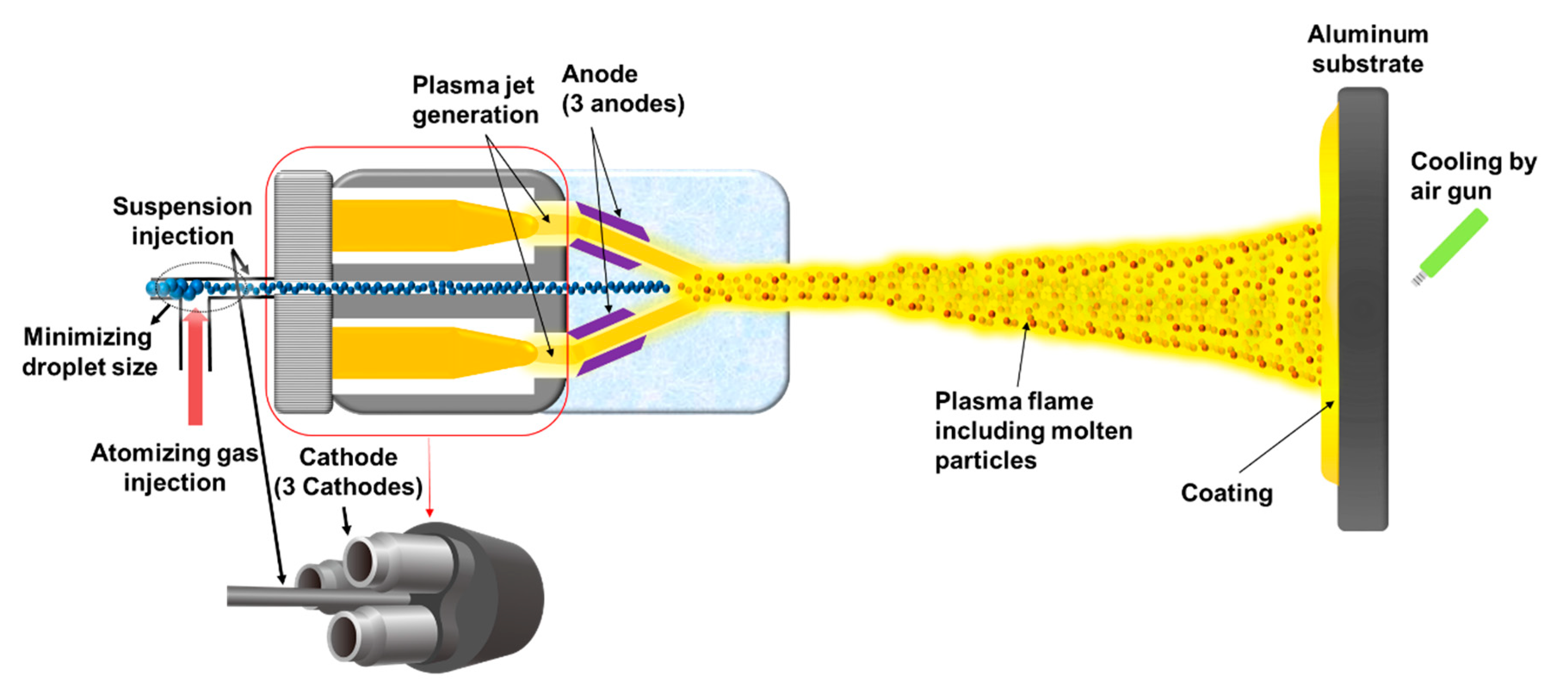
12]. Our previous works had focused on understanding the mechanism of the SPS process and on the optimum process conditions for the dense YOF coating.
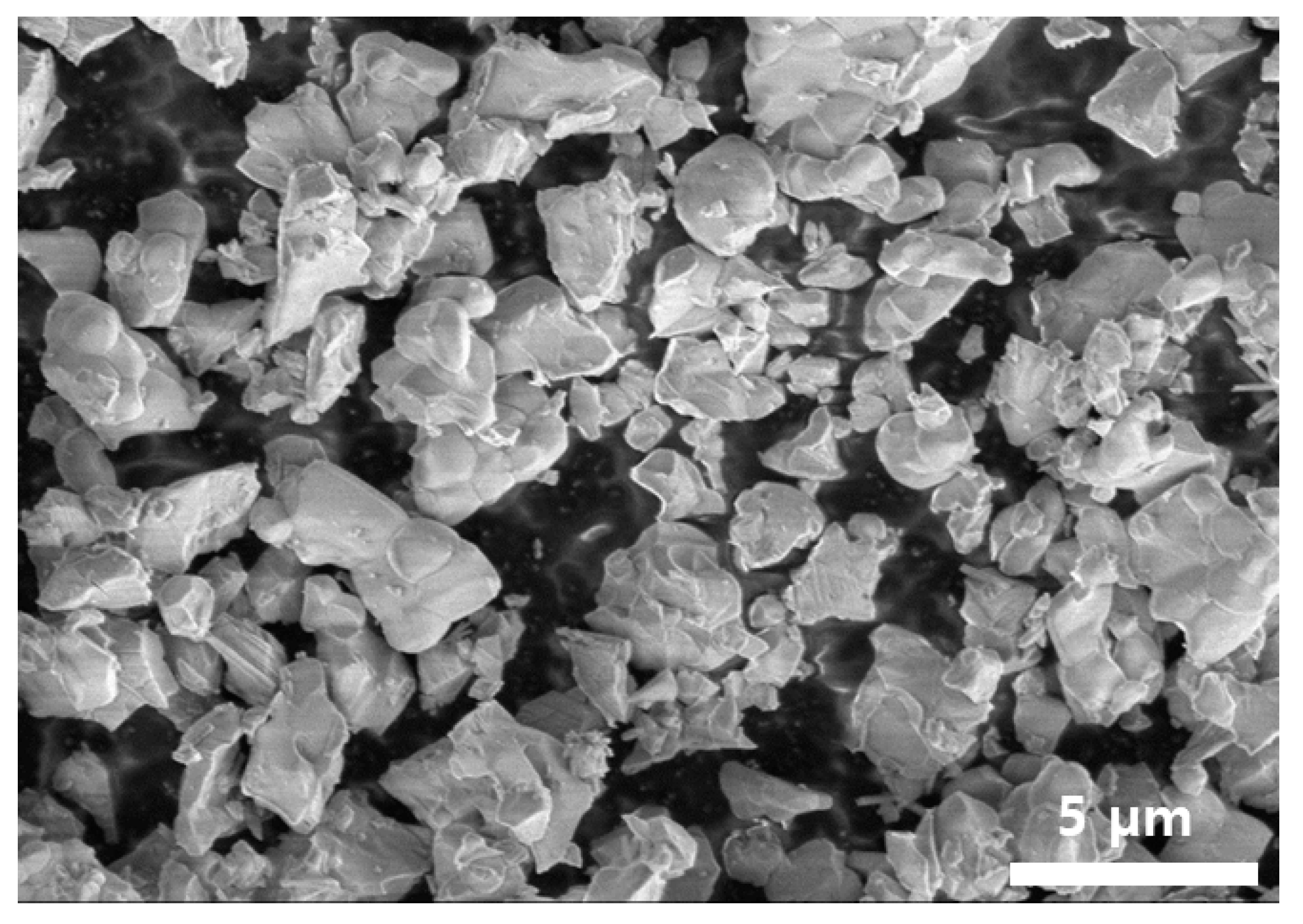
In the SPS process, it was found that the quality of the suspension plays a critical role in the YOF coating. If the Y5O4F7 suspension is in poor conditions due to the severe flocculation, the suspension feeding would be unstable during the SPS process, and large pores and cracks may form in the YOF coating due to incomplete melting of the particles. In this study, the influence of the stability and particle size of the Y5O4F7 suspension on the YOF coating behavior was investigated in order to develop a suspension suitable for the dense YOF coating by the SPS process. Electrostatically and electrosterically stabilized aqueous Y5O4F7 suspensions were prepared and evaluated based on the wettability and dispersibility, which were compared with those of a commercially available Y5O4F7 suspension without dispersant. The optimum stabilization condition and formulations of the Y5O4F7 suspension for the dense YOF coating by the SPS process were determined.
3. Results and Discussion
Figure 4 shows zeta potential measurements of aqueous Y
5O
4F
7 suspensions containing two types of dispersants (BYK-154 and BYK-199) and the commercially available Y
5O
4F
7 suspension without dispersant by the ELS method as a function of pH. The zeta potential represents the dispersibility by the charge repulsion between particles in suspensions. The repulsive interaction between Y
5O
4F
7 particles results from an electric double layer of the particle surface and is affected by the concentration of adsorbed ions and the ionic strength of the suspension [
16]. The zeta potential increases with the thickness of the electric double layer and the total charge of the particle surface [
17]. The suspension stability is closely related to a high zeta potential of the particles in suspension [
18].
The isoelectric point (IEP) of particles in suspensions represents the pH at which the zeta potential becomes zero. It indicates no net charge at the particles surface, which means the sum of the negative and positive charges is zero. As the pH of the suspension increases above or decreases below the IEP, the zeta potential of the aqueous Y
5O
4F
7 suspension becomes negative or positive, resulting from the adsorption of OH
− and H
+ ions toward Y
5O
4F
7 particles [
19].
Figure 4 shows that the IEP of the Y
5O
4F
7 suspension without dispersant was the pH of 8.1, and the initial pH of the suspension before titration, which has the zeta potential of −8.58 mV, was 8.6. This means the charge repulsion between the particles was not strong enough to repel each other. As a result, the agglomeration of the Y
5O
4F
7 particles would occur due to low surface charge densities of the particles.
To stabilize the aqueous Y
5O
4F
7 suspension and thereby to prevent the agglomeration of particles, two types of dispersants were used. One is the electrostatic dispersant (BYK-154), which utilizes the electrostatic stabilization by the repulsive force of equally charged particles. The other is the electrosteric dispersant (BYK-199), which utilizes stabilization by the steric effects in addition to the electrostatic repulsion due to the presence of electric charges along the polymer chain [
20].
If the zeta potential of the suspension is higher than ±30 mV, it is known to have moderate stability, and if it is higher than ±40 mV, it is known to have good stability [
15]. As the pH of the Y
5O
4F
7 suspension decreases toward acidic pH below IEP, the positive zeta potential may increase, and then the stability of the suspension may increase. However, since the acidic suspension corrodes metals, supplying it to the SPS equipment would damage the equipment. On the other hand, as the pH of the Y
5O
4F
7 suspension increases toward basic pH above IEP, the negative zeta potential may increase. However, since the silicone-containing defoamer (BYK-019) loses its function above pH 10, the foaming may occur and feeding of the suspension would become unstable during stirring in the SPS process. Therefore, the Y
5O
4F
7 suspension suitable for the SPS process should not be too acidic nor too basic. For these reasons, we wanted to create a stable Y
5O
4F
7 suspension with a zeta potential higher than ±40 mV at around the initial pH of 8.6.
It was observed that when the electrostatic dispersant (BYK-154) and electrosteric dispersant (BYK-199) were added to the Y
5O
4F
7 suspension, the IEP of the Y
5O
4F
7 particles in the suspension shifted to more acidic values from 8.1 to 3.9 and 2.4, respectively. The IEP shift was attributed to the adsorption of the negatively charged dispersant onto the positively charged surface of the Y
5O
4F
7 particles [
21]. The zeta potential of the electrostatically and electrosterically stabilized Y
5O
4F
7 suspensions was measured as −47.56 and −43.88 mV at pH of 8.6, respectively. The dispersants increased the electrical double layer of the surface of Y
5O
4F
7 particles, and the charge density of the particle surface was high enough to repel each other. From these results, it was found that the electrostatic and electrosteric dispersant (BYK-154 and BYK-199) had an effect of improving the stability of the Y
5O
4F
7 suspension. Therefore, the prepared Y
5O
4F
7 suspensions turned out to have much better redispersibility than that of the commercially available Y
5O
4F
7 suspension without dispersant.
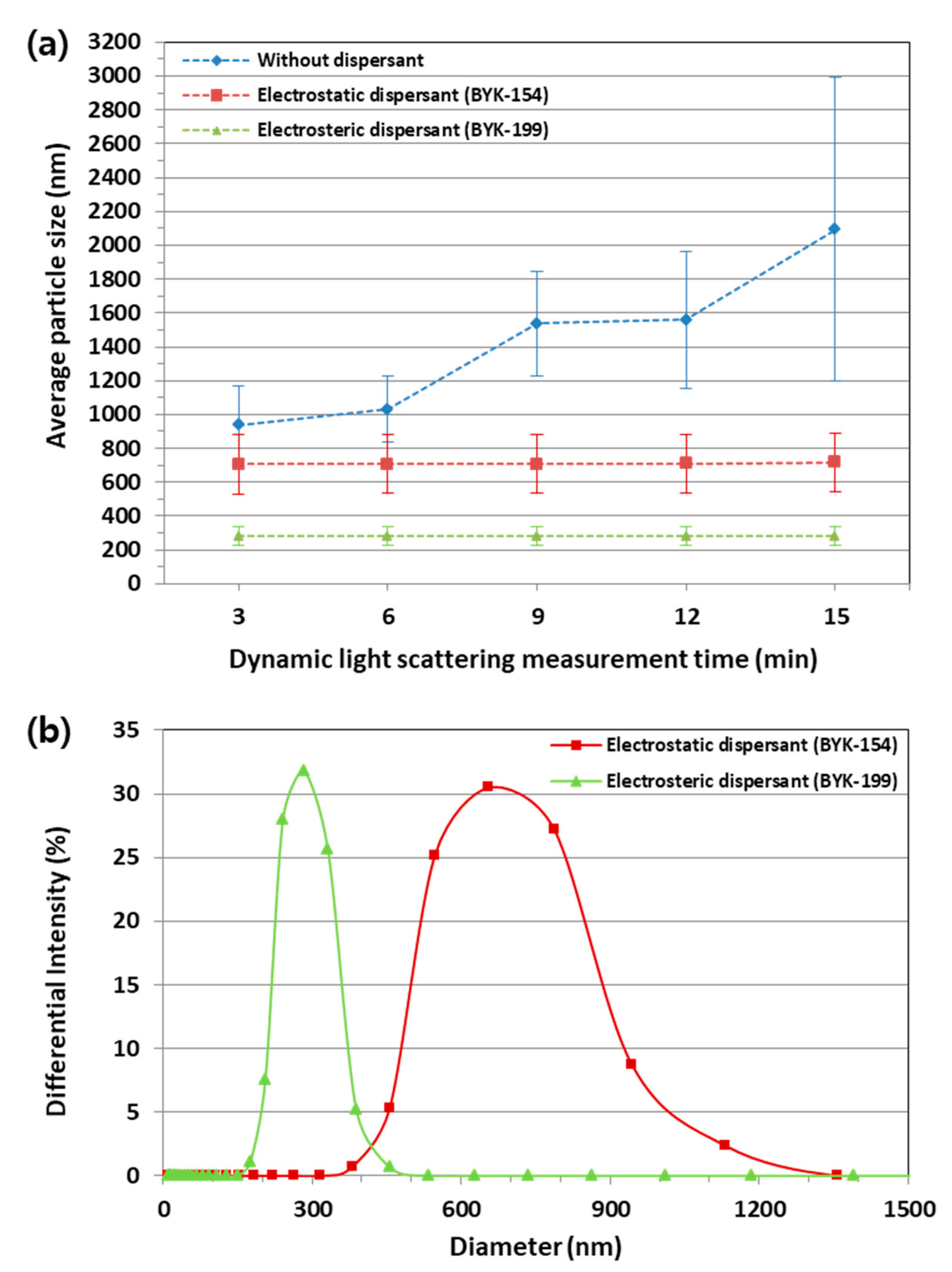
Figure 5 shows the average particle size measured in real time for 15 min at 3 min intervals and particle size distributions of Y
5O
4F
7 suspensions by DLS. As shown in
Figure 5a, the particle size of Y
5O
4F
7 suspension without dispersant gradually increased due to the agglomeration of the Y
5O
4F
7 particles with the measurement time. Because the agglomeration continued to take place, the average particle size could not be accurately determined. If the agglomeration of the Y
5O
4F
7 particles becomes severe, it can block the feeding line and may cause unstable feeding during the SPS process. In the Y
5O
4F
7 suspension with the electrostatic dispersant (BYK-154) and electrosteric dispersant (BYK-199), however, the agglomeration occurred in a much less degree and the average particle size remained constant as about 716 and 281 nm, respectively. As seen from these results, the size of the electrosterically stabilized Y
5O
4F
7 particles was much smaller than that of the electrostatically stabilized Y
5O
4F
7 particles. This difference cannot be explained simply by the difference in the zeta potential. The zeta potential of the suspension with the two types of dispersants was measured as −47.56 and −43.88 mV at a pH of 8.6, respectively, and there was no big difference in zeta potential. It could be inferred that this difference in average particle size was attributed to the difference in wettability between the suspensions. The wettability is related with the interfacial energy between the particles and the solvent, which would be affected by the adsorption of the dispersant.
Figure 5b shows that the electrosterically stabilized Y
5O
4F
7 particles had a smaller size and narrower size distribution than those of the electrostatically stabilized Y
5O
4F
7 particles. This means that the electrosterically stabilized Y
5O
4F
7 particles, which were initially agglomerated, had much better wettability with the solvent than that of the electrostatically stabilized ones and were disintegrated into small particles in the suspension. This is because the electrosteric dispersant (BYK-199) has a copolymer with much higher molecular weight than that of the electrostatic dispersant (BYK-154). The copolymer with higher molecular weight is known to lower the surface tension of the particles in the suspension by being adsorbed onto their surface more than that with lower molecular weight as the former has a higher surface activity [
22]. After wetting, the disintegrated electrosterically stabilized Y
5O
4F
7 particles would not be agglomerated and thereby the almost uniform size of the particles would be maintained by the steric effect and charge repulsion due to the high zeta potential of −43.88 mV. Therefore, it was confirmed that the electrosteric stabilization was highly effective in improving the wettability and dispersibility of the Y
5O
4F
7 suspension and would be advantageous for the stable feeding of the tiny Y
5O
4F
7 particles in the SPS process.
The stability of the Y
5O
4F
7 suspensions was evaluated by the sedimentation test for 24 h at room temperature. The result is shown in
Figure 6, where the relative sedimentation heights of the electrostatically and electrosterically stabilized Y
5O
4F
7 suspensions and the commercially available Y
5O
4F
7 suspension without dispersant were compared as a function of time. The relative sedimentation height of the suspensions was determined based on the interface between the supernatant with the highest transparency and the opaque suspension. The Y
5O
4F
7 suspension without dispersant shows the lowest sedimentation height. This is because the agglomeration of Y
5O
4F
7 particles occurred in the suspension very quickly due to the absence of dispersant and therefore the particle size increased, accelerating the sedimentation rate. After 24 h, the agglomeration and sedimentation of the particles formed a hard cake, which was difficult to redisperse.
On the other hand, the sedimentation rate of the electrosterically stabilized Y5O4F7 suspension was the slowest, followed by the electrostatically stabilized one. This is because the electrosterically stabilized Y5O4F7 particles had good wettability and the size of the particles remained small over time, so they had been floating in the suspension for a longer time. In addition, both suspensions with the two types of dispersants did not form a hard cake and were well redispersed after 24 h. As a result, the electrosterically stabilized Y5O4F7 suspension exhibits the best performance in terms of suspension stability.
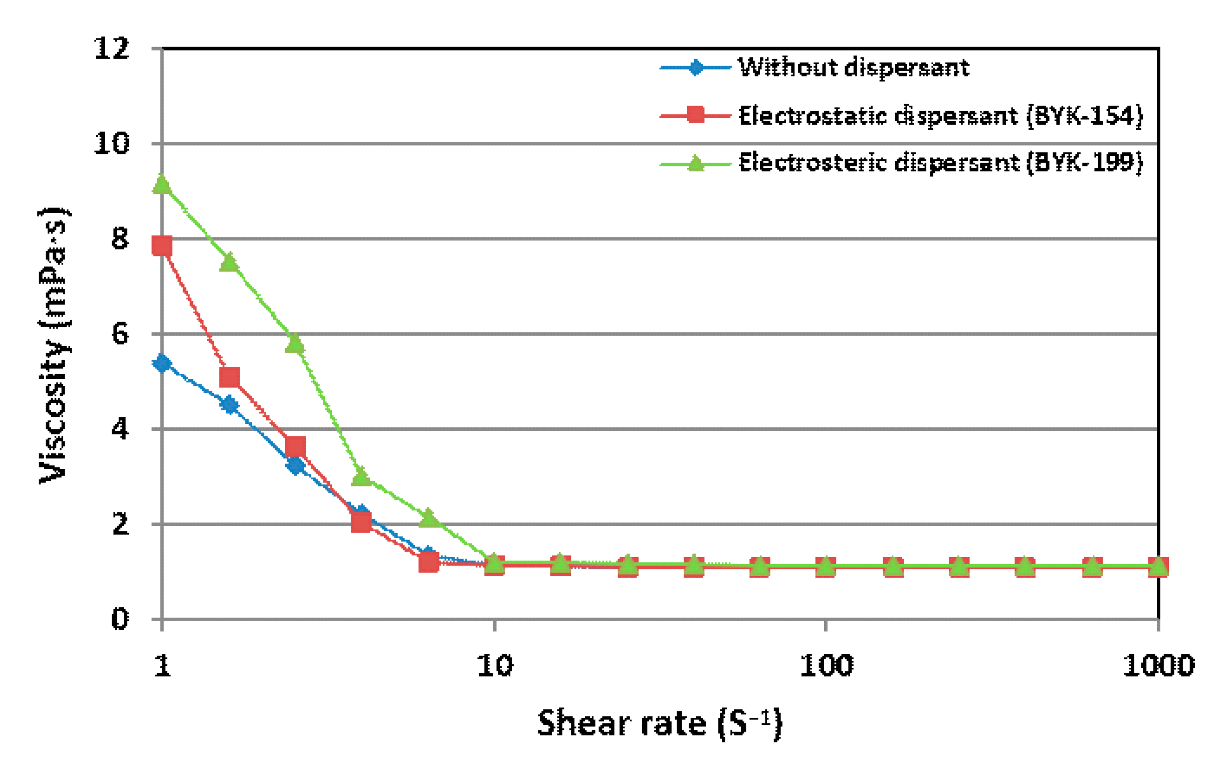
Figure 7 shows the viscosity of Y
5O
4F
7 suspensions of 10 wt.% solid content with the electrostatic, electrosteric dispersant, and without dispersant as a function of the shear rate at room temperature. The viscosity of the suspensions was almost constant at shear rates higher than 10 S
−1. The viscosity of Y
5O
4F
7 suspension without dispersant was 1.14 mPa·s measured by the rotational rheometer and those of Y
5O
4F
7 suspension with the electrostatic and electrosteric dispersant were 1.08 and 1.10 mPa·s, respectively. All of these Y
5O
4F
7 suspensions were prepared in an aqueous dispersing medium and their viscosities were almost similar to that of deionized water, which was 1.00 mPa·s at room temperature. The viscosity of the suspension is closely related to the fragmentation behavior of the suspension by the pressure of atomizing gas in the SPS process, and a low viscosity of the suspension is known to facilitate the atomization, decreasing the size of the suspension droplets [
23]. Since the viscosities of the suspensions were similar, the atomization effect on the fragmentation would be similar. Therefore, the stability and particles size of the Y
5O
4F
7 suspensions would be the main factors that affect the YOF coating in the SPS process.
Since the commercially available Y
5O
4F
7 suspension had no dispersant, the suspension became so severely flocculated that the hard cake was formed and could not be redispersed after sedimentation. If this Y
5O
4F
7 suspension is used in the SPS process, a very poor quality of the YOF coating is expected. Indeed, such an aspect is shown in
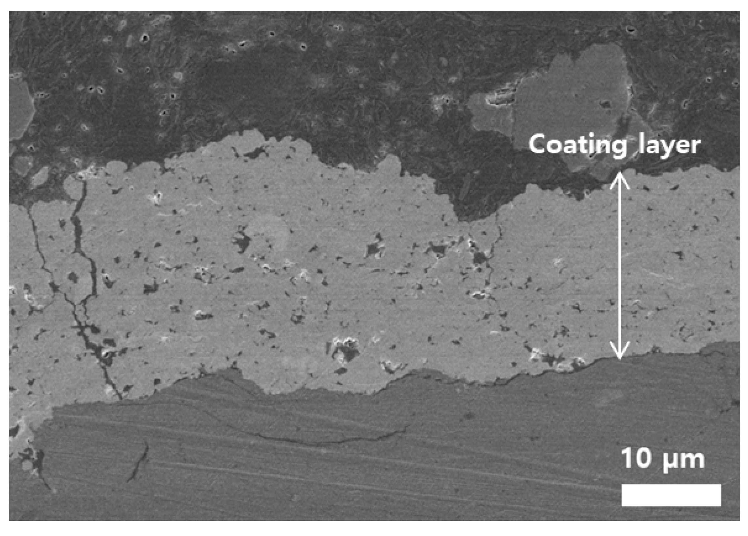
Figure 8, which is the FE-SEM image of the cross-section of the YOF coating deposited with the severely flocculated commercially available Y
5O
4F
7 suspension without dispersant by the SPS process. The thickness of the YOF coating was 20 ± 2.5 µm. As shown in
Figure 8, when the YOF coating was deposited using such Y
5O
4F
7 suspension, many large pores and even cracks were observed throughout the YOF coating. Large, agglomerated particles resulting from severe flocculation would not be fully melted even by the sufficient thermal energy from the high-power plasma flame during the SPS process, which would not only reduce the growth rate, but also produce large pores and cracks in the YOF coating. In addition, the severely agglomerated Y
5O
4F
7 particles resulted in unstable feeding throughout the feeding line during the SPS process. The feeding rate was not stable but varied abruptly away from the initial setting value during the process. Therefore, the stability of the Y
5O
4F
7 suspension had a great influence on the microstructure of YOF coating in the SPS process.
For that reason, the commercially available Y
5O
4F
7 suspension without dispersant, which had not yet been severely flocculated prior to the process, was used in the process, and the YOF coating behavior was compared with that from the prepared electrostatically and electrosterically stabilized Y
5O
4F
7 suspensions under the same conditions.
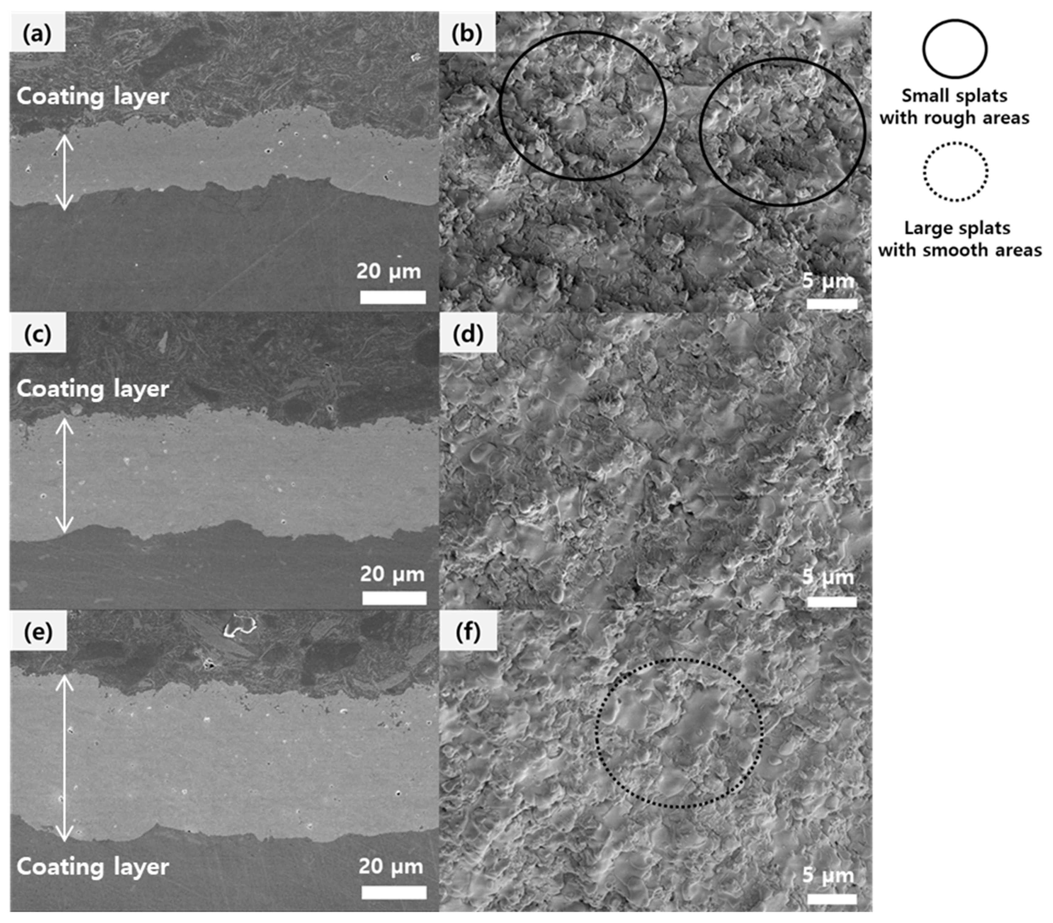
Figure 9 shows FE-SEM images of YOF coatings deposited by the SPS process. The YOF coatings have a crystalline structure of a trigonal phase, as we had previously reported [
7,
9].
Figure 9a,b shows the cross-section and the surface of the YOF coating deposited using the commercially available Y
5O
4F
7 suspension without dispersant.
Figure 9c,d shows the cross-section and the surface of the YOF coating deposited using the electrostatically stabilized Y
5O
4F
7 suspension.
Figure 9e,f shows the cross-section and the surface of the YOF coating deposited using the electrosterically stabilized Y
5O
4F
7 suspension. Thicknesses of the YOF coatings in
Figure 9a,c,e were 20 ± 1.2, 30 ± 1.3 and 40 ± 1.5 µm, respectively. This result shows that the electrosterically stabilized Y
5O
4F
7 suspension achieved the highest coating rate, followed by the electrostatically stabilized Y
5O
4F
7 suspension, and the Y
5O
4F
7 suspension without dispersant resulted in the lowest rate. Quantitatively, the electrosterically stabilized Y
5O
4F
7 suspension produced the coating rate about twice as high as that of the commercially available Y
5O
4F
7 suspension without dispersant.
Figure 9b,d,f show that the FE-SEM images of surface morphologies of YOF coatings consist of smooth areas with large splats and rough areas with small splats. The completely melted particles spread over the growing surface and form smooth areas called splats [
24]. However, the partially or incompletely melted particles form small splats producing rough areas throughout the YOF coating. In
Figure 9b, the small splats with rough areas were observed over the entire surface of the YOF coating, implying that the agglomerated particles in the Y
5O
4F
7 suspension without dispersant were partially or incompletely melted. On the other hand, in
Figure 9f, the large splats with smooth areas were observed over the entire surface, implying that the electrosterically stabilized Y
5O
4F
7 particles were well dispersed in the suspension with small particle sizes (~281 nm in
Figure 5) and thus completely melted.
No cracks were observed in the cross-section images of the YOF coatings as shown in
Figure 9. The YOF coatings in
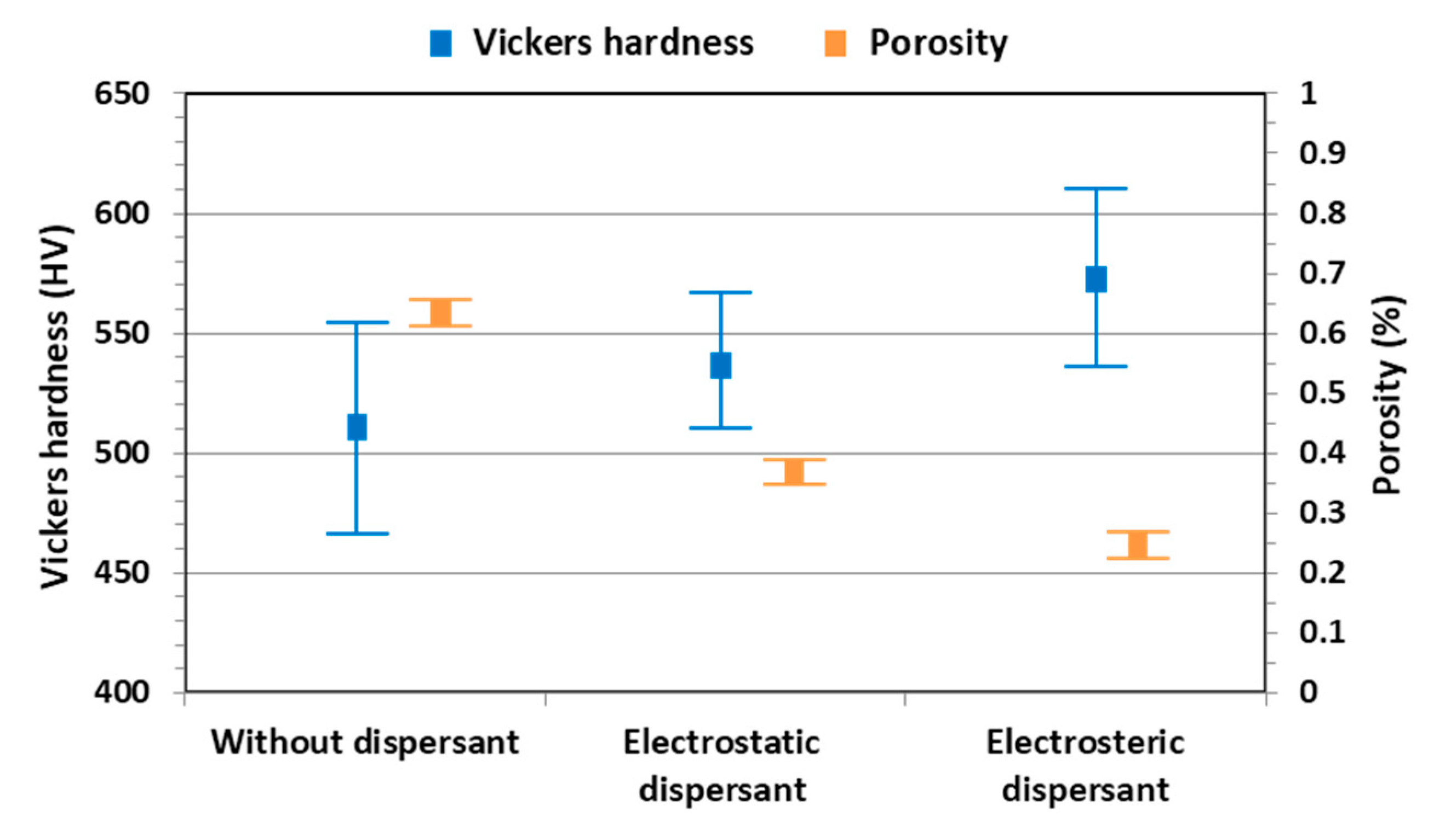
Figure 9a,e had the highest and lowest porosities, respectively, which are closely related with hardness. The porosity and the Vickers hardness of YOF coatings are shown in
Figure 10. The Vickers hardness of the YOF coating deposited with the Y
5O
4F
7 suspension without dispersant was 511 ± 45 HV, and those of the YOF coatings deposited with the electrostatically and electrosterically stabilized Y
5O
4F
7 suspensions were 531 ± 35 and 570 ± 44 HV, respectively. The porosities of the YOF coatings in
Figure 9a,c,e were 0.66% ± 0.02%, 0.37% ± 0.01%, and 0.24% ± 0.01%, respectively. As a result, the YOF coating deposited with elctrosterically stabilized Y
5O
4F
7 suspension had the highest hardness and the lowest porosity.
The differences in the coating rate and the microstructure are attributed to the stability and particle size of the Y
5O
4F
7 suspension. Since the evaporation process is endothermic, about 25% of the plasma jet enthalpy is consumed in the evaporation of the solvent in the droplets and Y
5O
4F
7 particles are melted by the remaining thermal energy in the plasma flame after evaporation of the droplets [
25]. For that reason, the smaller the size of the dispersed Y
5O
4F
7 particles in the droplets is, the more advantageous it is to deposit the dense YOF coating by the SPS process. The electrosterically stabilized Y
5O
4F
7 particles were well dispersed in such small particle sizes that they would completely melt by the remaining thermal energy, increasing the deposition rate and decreasing the porosity of the YOF coating. On the other hand, since some of the agglomerated Y
5O
4F
7 particles in the suspension without dispersant did not melt and remained in solid form, most of them were bounced away from the substrate during the process. In other words, the fully or partially melted Y
5O
4F
7 particles contribute to the deposition rate and dense microstructure of the YOF coating, but the unmelted Y
5O
4F
7 particles could not do so. From these results, the stability and particle size of the Y
5O
4F
7 suspension had significant effects on the coating efficiency and microstructure of the YOF coating in the SPS process. Therefore, the electrosterically stabilized Y
5O
4F
7 suspension turned out to be the most suitable for the high coating efficiency and the dense microstructure of the YOF coating by the SPS process.
