1. Introduction
The moth-eye nanostructure has been widely used to reduce the surface reflection on optoelectronic products, such as liquid crystal display (LCD) [
1,
2], solar cell [
3,
4], image sensor [
5], etc. Inspired by nature, the moth-eye nanostructure is a nipple array, typically of nano-scale height and diameter [
6]. Its antireflection performance is closely related to structural accuracy, and therefore high-precision fabrication of moth-eye nanostructure is critical [
7]. Among various fabrication technologies, the ultraviolet nanoimprint lithography (UV-NIL) provides an effective solution for the high-precision fabrication of moth-eye nanostructure [
8,
9], which mainly includes liquid resin filling into the mold cavity and UV-curing process. The filling process is core during UV-NIL of moth-eye nanostructure, which determines the final forming accuracy, so an accurate analysis of the resin filling behavior is necessary [
10,
11]. However, the moth-eye nanostructure is generally tens to hundreds of nanometers [
12,
13], and it is quite difficult to analyze the resin filling behavior through the experimental method. Therefore, numerical simulation is commonly adopted to investigate the resin filling behavior in micro/nano-scale [
14,
15].
Various researches have been carried out to investigate the resin filling behavior in the UV-NIL process. Kim et al. [
16] studied the effects of contact angle and aspect ratio on the resin filling behavior, and it was found that complete filling occurred when the contact angle on the vertical wall was as low as that on the substrate. Lai et al. [
17,
18] investigated the effects of process parameters on bubble defects during roll-to-roll ultraviolet nanoimprint lithography (R2R UV-NIL) of the micro-pyramid array. Tian et al. [
19] proposed a simulation model to predict the electrically induced pattern formation, which considered the effects of electrostatic force-assisted and electrocapillary force-driven. Nagaoka et al. [
20] studied the resin filling characteristics under a condensable gas ambient, and it was found the gas ambient had a significant impact on the resin filling behavior. Shibata et al. [
21] established a simulation system to investigate the UV-NIL process, which was composed of the resin filling module, optical-intensity distribution module, mechanical properties module and shrinkage module. Ye et al. [
22] analyzed the generation mechanism of bubble defects in the R2R UV-NIL process.
Although various researches have been reported to analyze resin filling behavior, the moth-eye nanostructure is generally tens to hundreds of nanometers and boundary slip has a significant effect on the filling behavior at this scale [
23,
24]. Few simulation studies have been reported considering the effect of boundary slip. The computational fluid dynamics (CFD) simulation is an effective method to predict the behavior of liquids and gases in an intelligent way, which is widely used in aerospace, automotive, energy and other fields. Therefore, a CFD simulation model was proposed in this paper, which considered the effect of boundary slip. Based on the proposed model, the effects of process parameters and boundary conditions on resin filling behavior were investigated. Besides, the simulation results were also compared with experimental results, and good agreement was found. This research could provide guidance for the accurate analysis of resin filling behavior during UV-NIL of moth-eye nanostructure.
2. Numerical Modeling
2.1. Physical Model
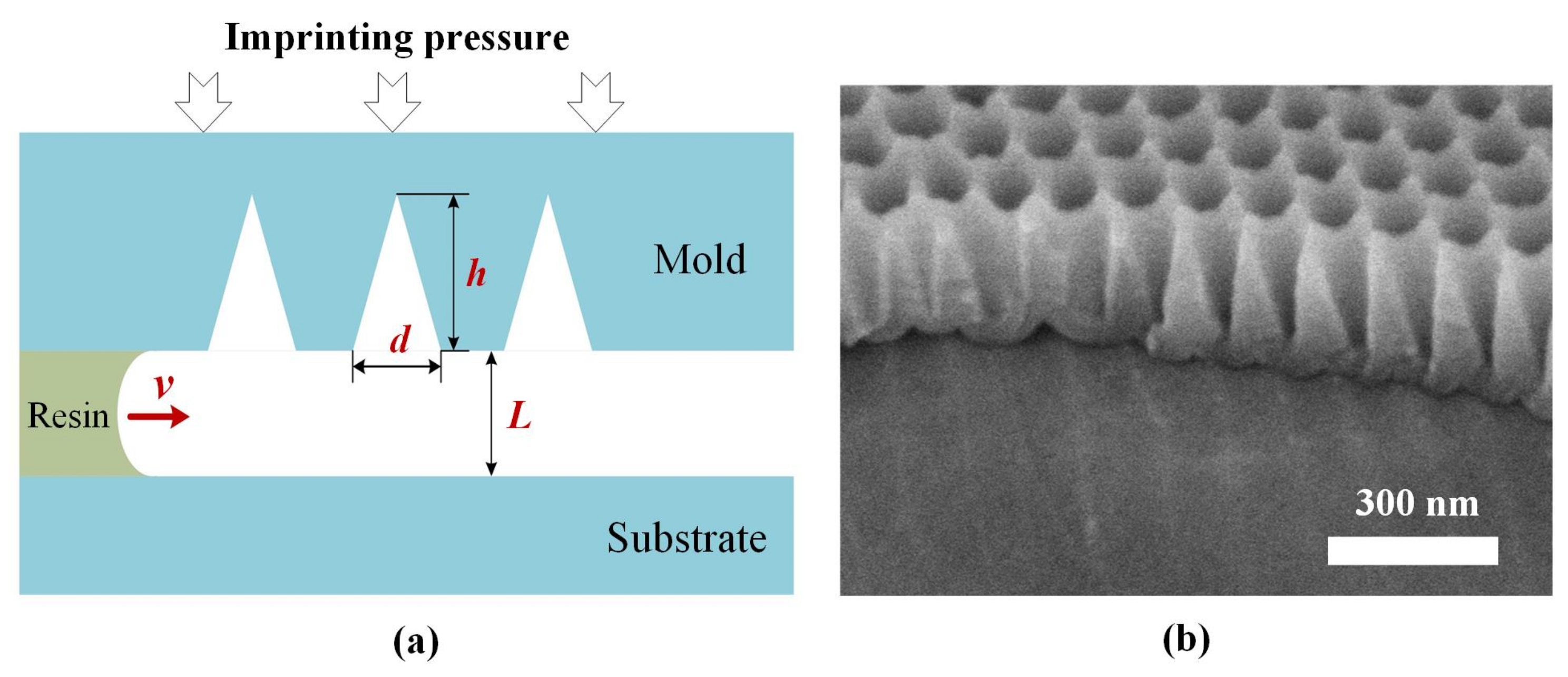
Figure 1a shows the schematic diagram of resin filling process during UV-NIL of moth-eye nanostructure, where
v is flow velocity of the resin,
d the diameter of moth-eye nanostructure,
h the height of moth-eye nanostructure and
L the resin thickness. The imprinting mold for moth-eye nanostructure is 90 nm in diameter and 180 nm in depth, as shown in
Figure 1b. A simulation model was built to investigate the resin filling behavior during UV-NIL of moth-eye nanostructure using the commercial program, ANSYS-Fluent, and the following assumptions were made to simplify the simulation process.
- (1)
As shown in
Figure 1b, the moth-eye nanostructure was rotationally symmetric, and therefore the simulation model was simplified to a two-dimensional model.
- (2)
The resin filling process was assumed as an incompressible steady laminar flow during UV-NIL of moth-eye nanostructure [
16,
25].
- (3)
The resin was assumed as an incompressible Newton fluid [
20,
26].
- (4)
It was assumed that the resin flowed into the gap between the mold and substrate from one side at a certain speed and out from the other side [
25].
2.2. Material Parameters
The material parameters could obviously affect filling behavior, so an accurate setting of material parameters in the simulation model was necessary. Two kinds of materials were included in the simulation model, that was air and resin. As one common material, the material parameters for air were chosen from a database in ANSYS-Fluent software (R15.0). The resin for fabrication of moth-eye nanostructure was a radical curing system developed by Jiangsu Kangde Xin Composite Material Co., Ltd. (Suzhou, China) [
7,
27] and its material parameters were obtained through experimental characterization, including viscosity, surface tension and wettability.
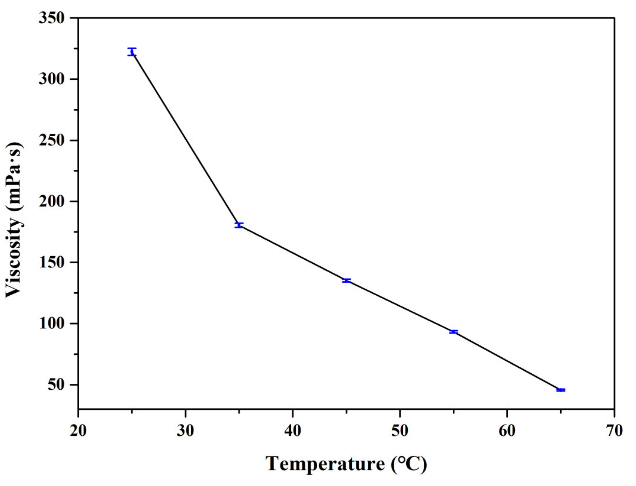
Figure 2 presented the viscosity property at different temperatures, which was obtained using the rotary viscometer (DV2T, Brookfield, Middleboro, MA, USA). It was found that the resin viscosity decreased as the temperature increased. When the temperature was raised from 25 °C to 65 °C, the resin viscosity was reduced from 322.3 mPa·s to 45.6 mPa·s. This phenomenon could be attributed to the thermal motion energy of polymer molecules that was larger with a higher temperature, which made the liquid internal pores increase in both number and volume, so the resin fluidity was better [
18].
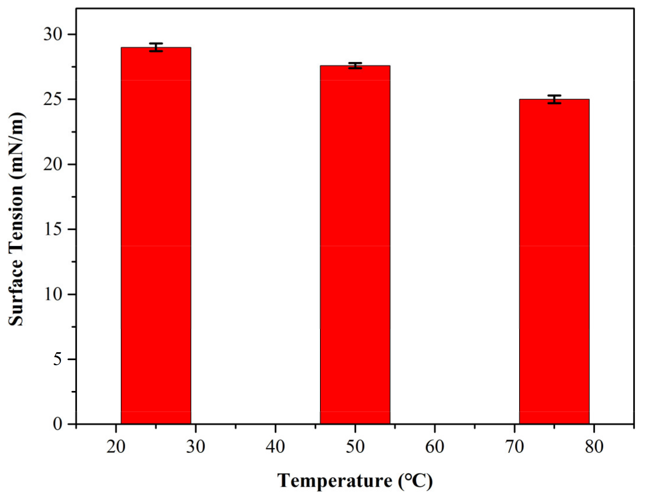
Figure 3 displayed the surface tension at different temperatures, which was obtained with a surface tension tester (K100, Kruss, Hamburg, Germany) and Wilhelmy method. The temperature was set as 25 °C, 50 °C, 75 °C, respectively. As shown in
Figure 3, the surface tension varied from 29.0 mN/m to 25.0 mN/m as the temperature was raised from 25 °C to 75 °C. The reason for this phenomenon was that the thermal motion became more intense inside the liquid, and the distance between molecules increased when the temperature rose, which caused the gravitational pull from the surface molecules to decrease accordingly. Moreover, the density of the gas phase and the gas stress relative to the surface molecules increased when the temperature rose. The two effects worked together, which caused surface tension to decrease at high temperatures [
17].
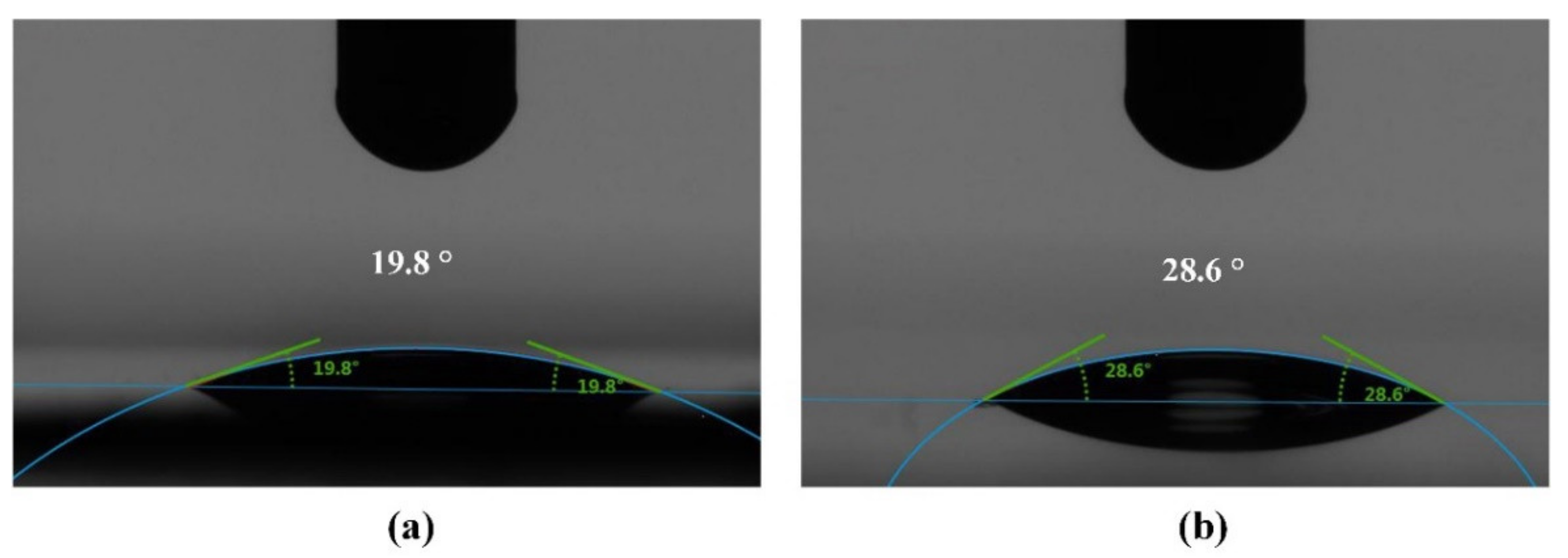
Figure 4 gave the contact angle measurements, which were obtained using the contact angle measuring instrument (DSA30, Kruss, Hamburg, Germany). The volume of the droplet for contact angle measurements was 3 µL. In order to ensure accuracy, at least five different positions were chosen to measure the contact angle on each sample surface, and the average of all measurements was taken as the contact angle of the sample surface. Based on the measurements, the contact angle between resin with mold and polyethylene terephthalate (PET) substrate was 21.5 ± 1.8° and 28.3 ± 2.1°, respectively.
Based on the experimental characterization above, the parameters in the simulation model were set as
Table 1.
2.3. Boundary Conditions
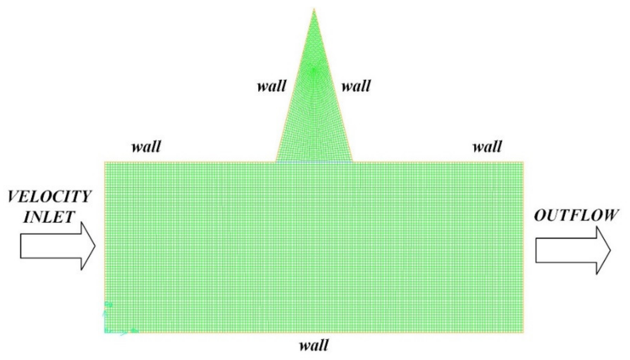
Figure 5 presented the boundary conditions in the simulation model. As shown in
Figure 1a, the resin flowed into the gap between the mold and substrate from one side at a certain speed and out from the other side. Therefore, the left side was considered to be the resin inlet, and the boundary condition was set as velocity inlet. The right side was considered to be the resin outlet, and the boundary condition was set as outflow. The top side was the impermeable mold surface, and the boundary condition was set as a wall. The bottom side was impermeable PET substrate, and the boundary condition was set as a wall. According to whether the slip occurred, the wall boundary condition could be further set as no-slip wall and slip wall.
2.4. Mathematic Equations
The Navier–Stokes equation was used to describe the resin flow behavior. Mass conservation was given by
where
u was the velocity in
x direction and
v was the velocity in y direction.
Momentum conservation was given by
where
p was the pressure,
the fluid density and
the fluid viscosity.
In the simulation model, the air was set as the primary phase, and the resin was set as the secondary phase. The volume of fluid (VOF) method was employed to track the interface between resin and air [
28,
29]. The VOF function
was defined in the entire flow field, which was the ratio of fluid volume to mesh volume in each mesh. A mesh that did not contain this fluid was called an empty mesh, a mesh that was filled with such a fluid was called a full mesh, and a mesh that contained an interface was called a half mesh. Assuming the calculation area was
and the fluid area was
, the following function was defined:
The equation
was satisfied in the flow field, and
was the velocity field. The VOF function
was defined as an integral of
on each mesh
.
The mesh with was full of fluid, the mesh with was called the empty mesh and the mesh with was called the boundary mesh. According to the value, the interface could be constructed.
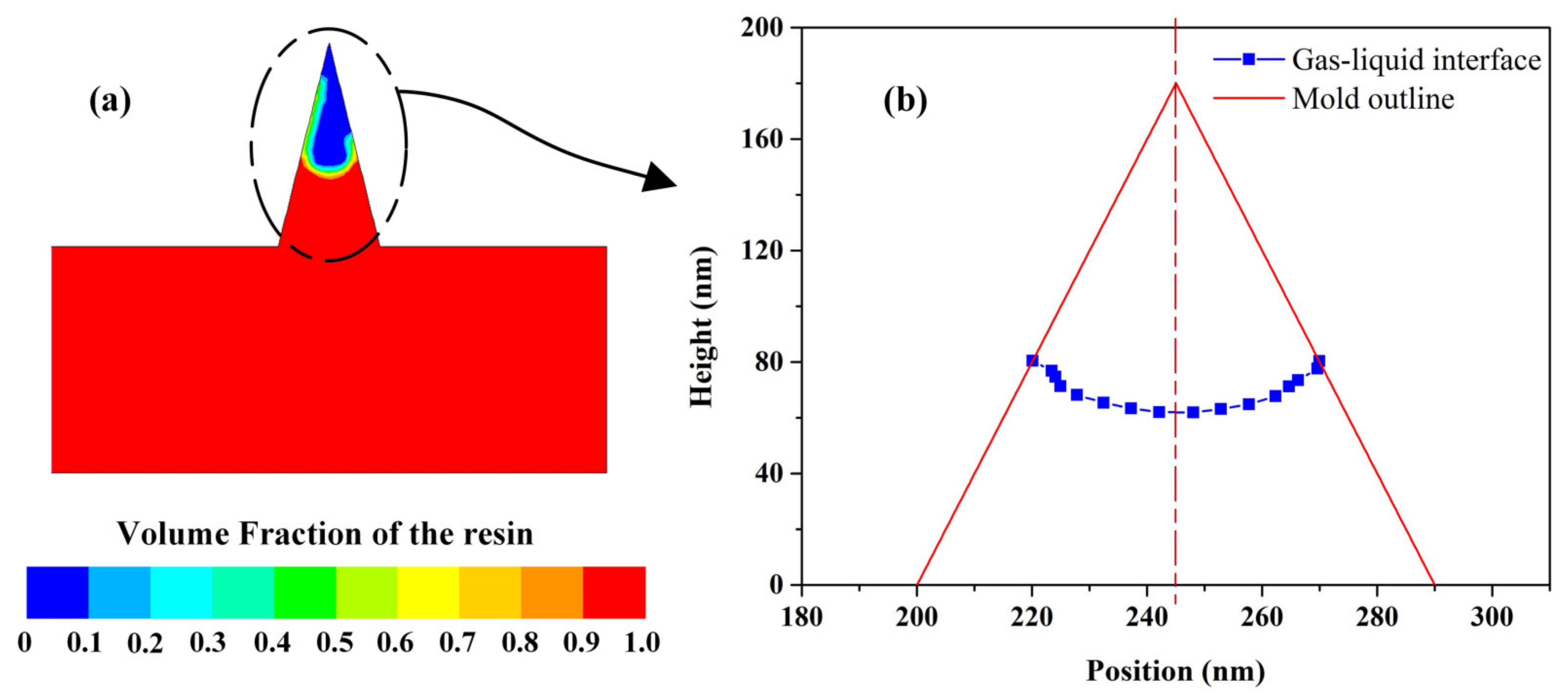
2.5. Evaluation Method
The filling height was adopted to describe the simulation results quantitatively, as shown in
Figure 6. After the filling process was completed, the simulation results were post-processed, and then the resin volume fraction in the mold cavity was derived. According to the cloud image of volume fraction, the interface between resin and air could be extracted. In this research, the height value at the mold center line was defined as filling height.
3. Results and Discussion
3.1. Effect of Process Parameters
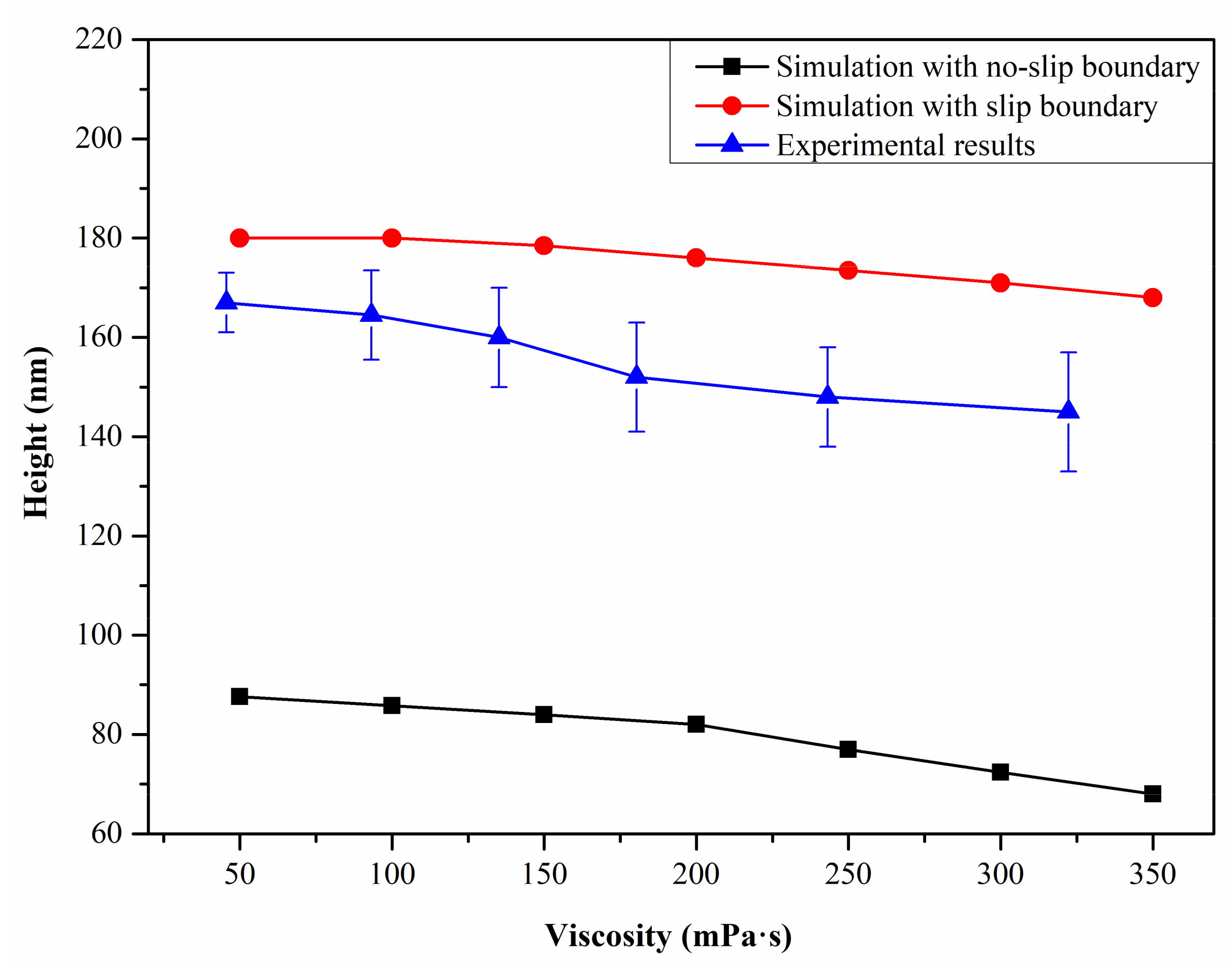
Figure 7 showed the effect of resin viscosity on the filling height of the moth-eye nanostructure. In order to ensure one single variable, the inlet velocity and resin thickness were set as 1 × 10
−5 m/s and 200 nm. As observed, the filling height decreased as the resin viscosity increased both with no-slip and slip boundaries. The reason for this phenomenon was that as the resin viscosity increased, the viscous resistance increased and less resin flowed into the mold cavity under the same conditions, thereby obtaining a lower filling height.
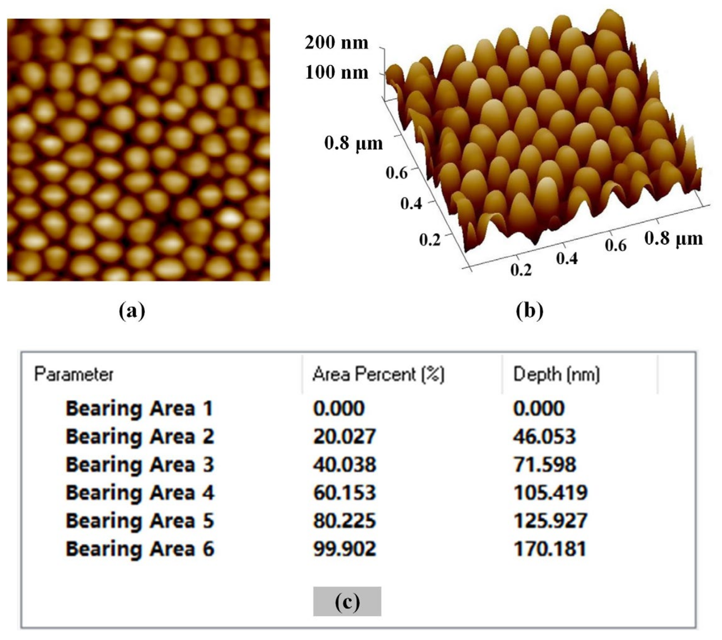
Figure 8 displayed the moth-eye nanostructures fabricated by the UV-NIL process, and geometric characterization was conducted using atomic force microscope (AFM) equipment (Dimension FastScan, Bruker, Karlsruhe, Germany). As presented in
Figure 8c, the forming height was acquired through bearing analysis of AFM images. It could be found that the simulation results with slip boundary were more compatible with the experimental results. The experimental results were slightly lower than the simulation heights, which might be caused by the curing shrink of the resin [
30,
31]. Based on the contrast between simulation and experimental results, the proposed simulation model considering the effect of boundary slip showed high accuracy, which could be used for the analysis of resin filling behavior during the UV-NIL of moth-eye nanostructure.
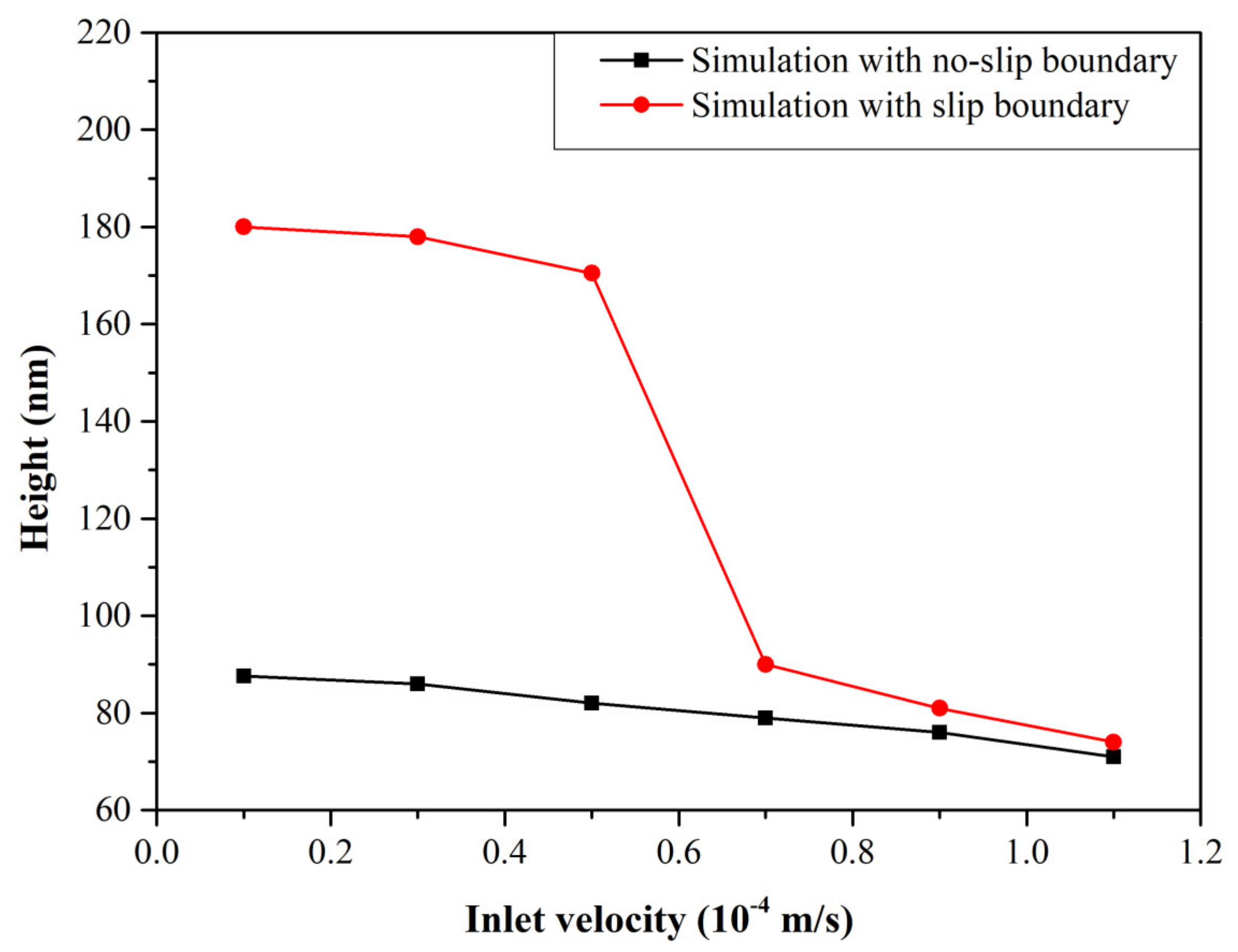
Figure 9 showed the effect of inlet velocity on the filling height of the moth-eye nanostructure. According to the simulation results, the filling height declined as the inlet velocity increased. It could be attributed to the mold cavity that was closed more quickly as the inlet velocity increased so that the resin volume flowing into the mold cavity decreased, eventually causing the height to decrease. Further analysis showed that a larger filling height could be obtained with slip boundary, which was because the resin near the mold side flowed faster than the substrate side, and more resin could be filled into the mold cavity before the cavity was closed. However, when the inlet velocity was larger than 7 × 10
−5 m/s, the filling height was almost the same with both slip and no-slip boundaries. This was because the filling height was affected by the boundary and initial condition simultaneously. When the initial inlet velocity became larger, the influence of boundary slip was weakened, and the final height was mainly affected by the inlet velocity [
32,
33].
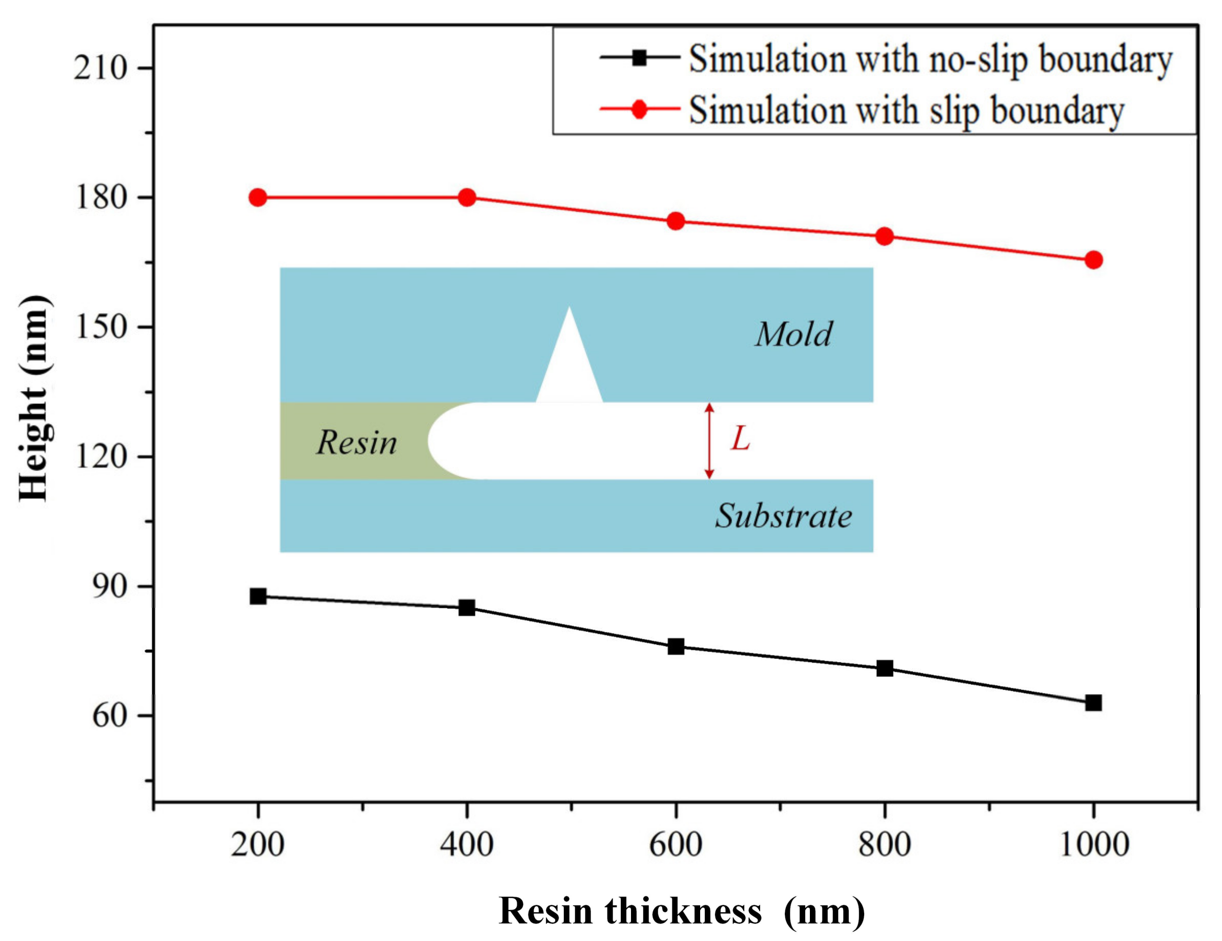
Figure 10 showed the effect of resin thickness on the filling height of moth-eye nanostructure. As observed, the filling height decreased as the resin thickness increased. It was because the resin thickness was adjusted by the imprinting pressure and smaller resin thickness meant a larger pressure. When the resin thickness became larger, the pressure decreased, and less resin was squeezed into the mold cavity, thereby causing a lower filling height. Besides, it was further found that a larger filling height could be obtained with slip boundary, which was because the slip on the mold caused the resin near the mold side to flow faster than the substrate side, and more resin could be filled into the mold cavity to obtain a larger filling height before the cavity was closed.
3.2. Effect of Slip Position
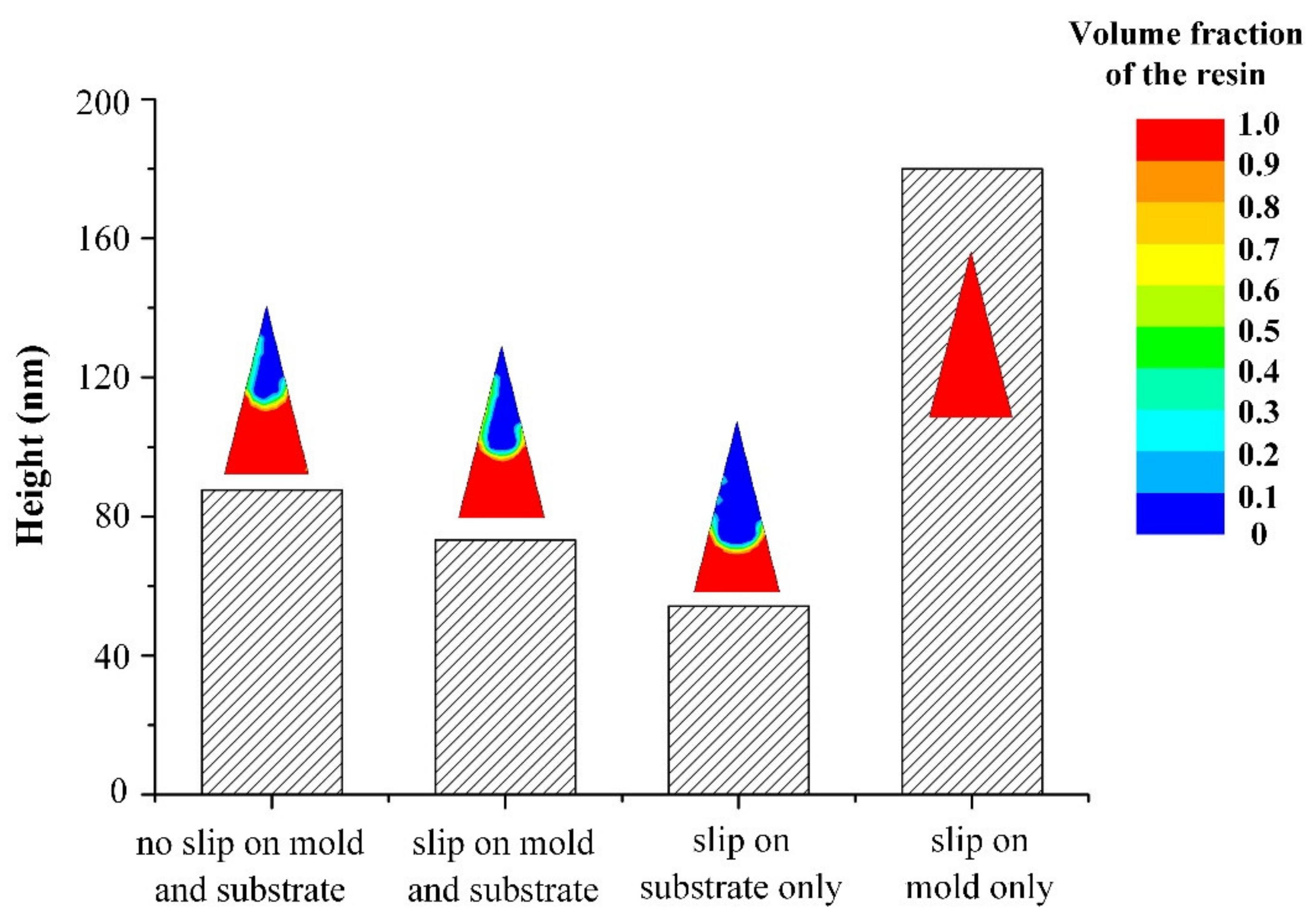
The boundary slip might occur on different positions, substrate side or mold side, and it was difficult to investigate the influence of slip position on filling behavior using the experimental method. Therefore, the effect of slip position on filling behavior was investigated based on the simulation model, as shown in
Figure 11. In order to ensure one single variable, the slip speed was set to the same value, which was 2.5 × 10
−5 m/s. According to the simulation results, the slip position showed a significant influence on the resin filling behavior, and the forming height was 87.6 nm, 73.2 nm, 54.3 nm and 180 nm with no-slip on both the mold and the substrate, slip on both the mold and the substrate, slip on the substrate only and slip on the mold only, respectively. Based on the results, it was concluded that the solid–liquid interface property had an important influence on the resin filling process, which affected the slip position.
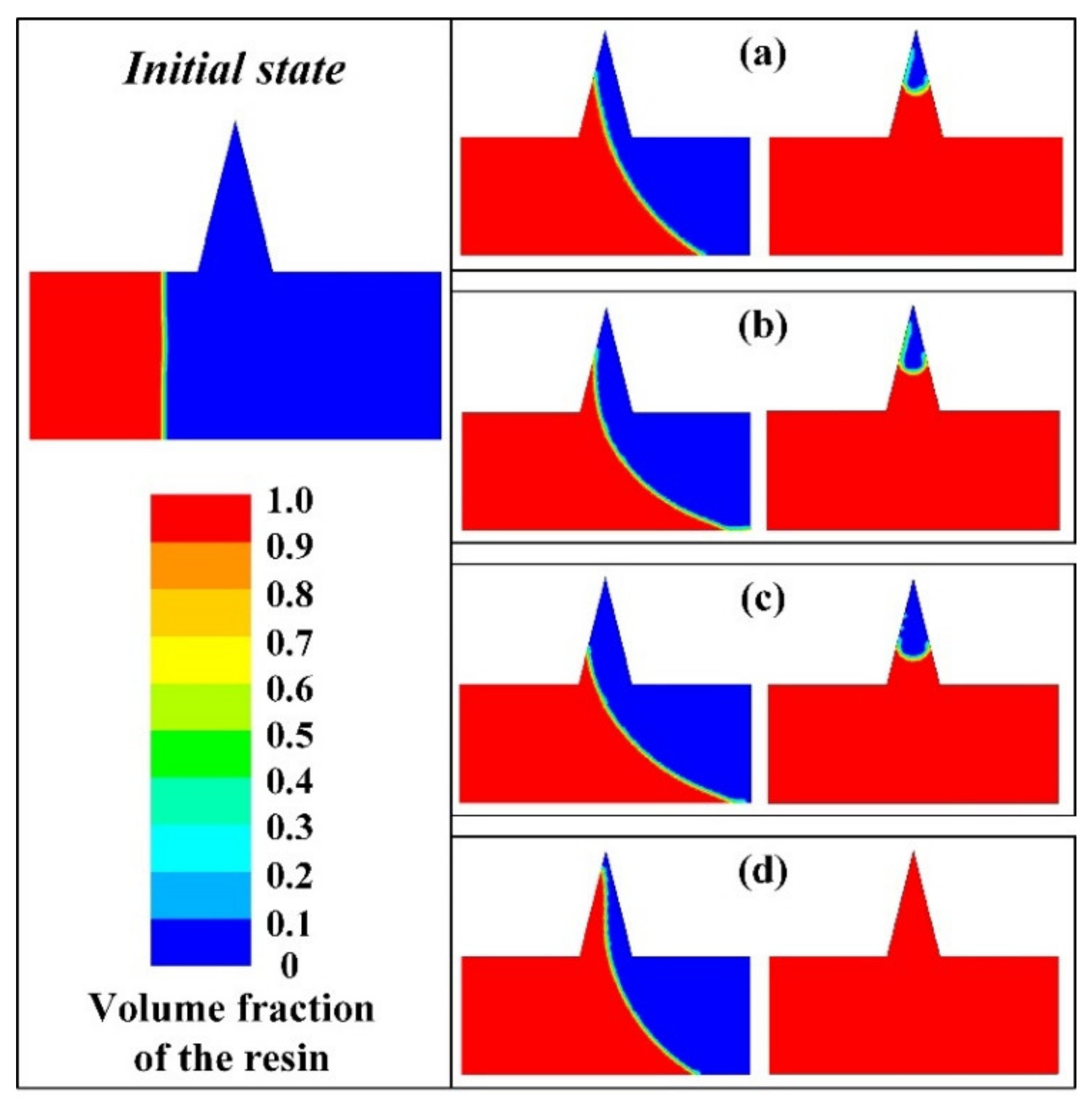
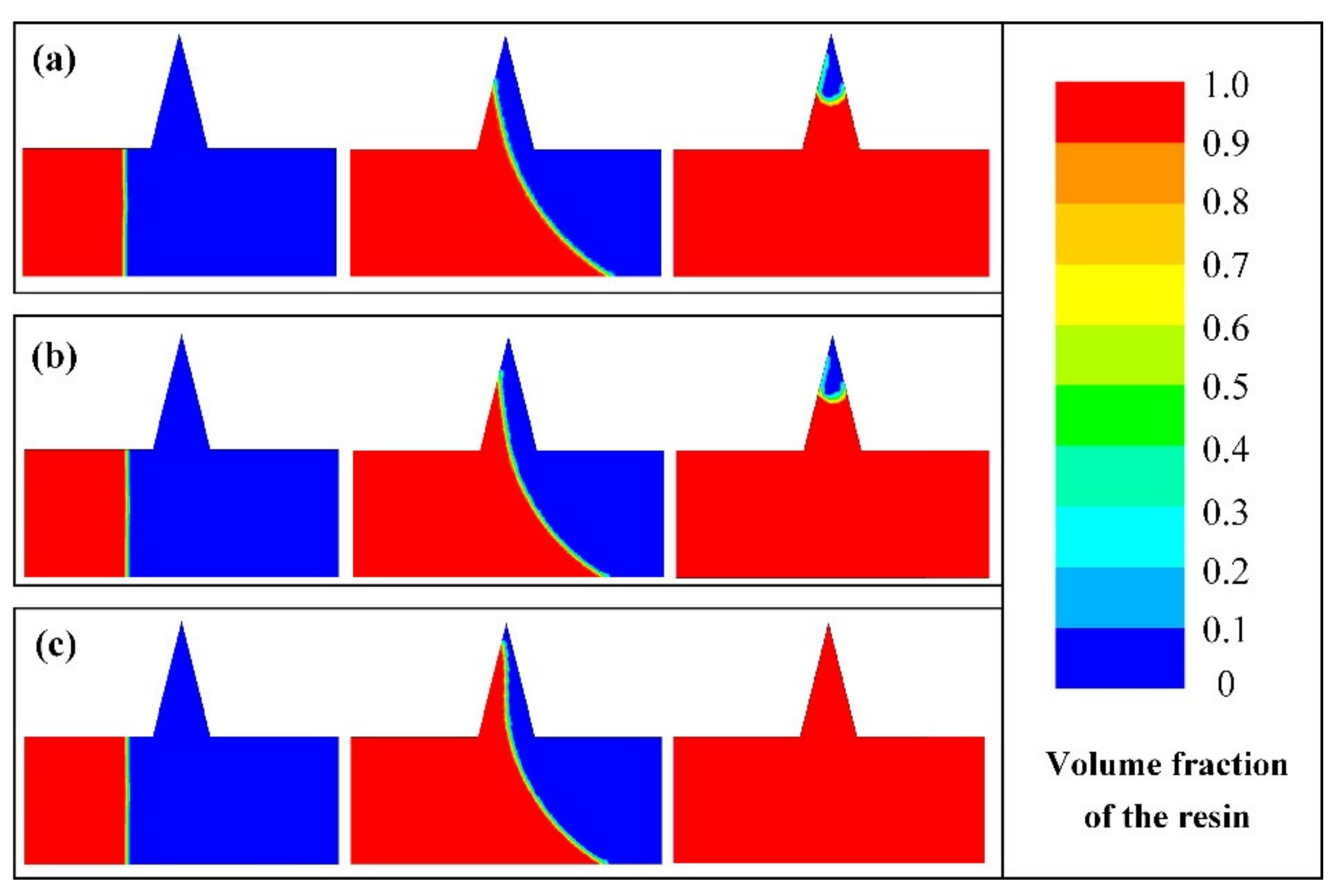
The resin filling evolution process with different slip positions was further investigated, as shown in
Figure 12. It could be found that the resin near the substrate flowed faster when boundary slip occurred on the substrate side only, so the cavity was closed more quickly, thereby lowering the filling height. Besides, it was observed from
Figure 12d that the resin near the mold side flowed faster when the boundary slip occurred on the mold side only, and more resin could flow into the mold cavity before the cavity was closed, thereby obtaining a larger filling height.
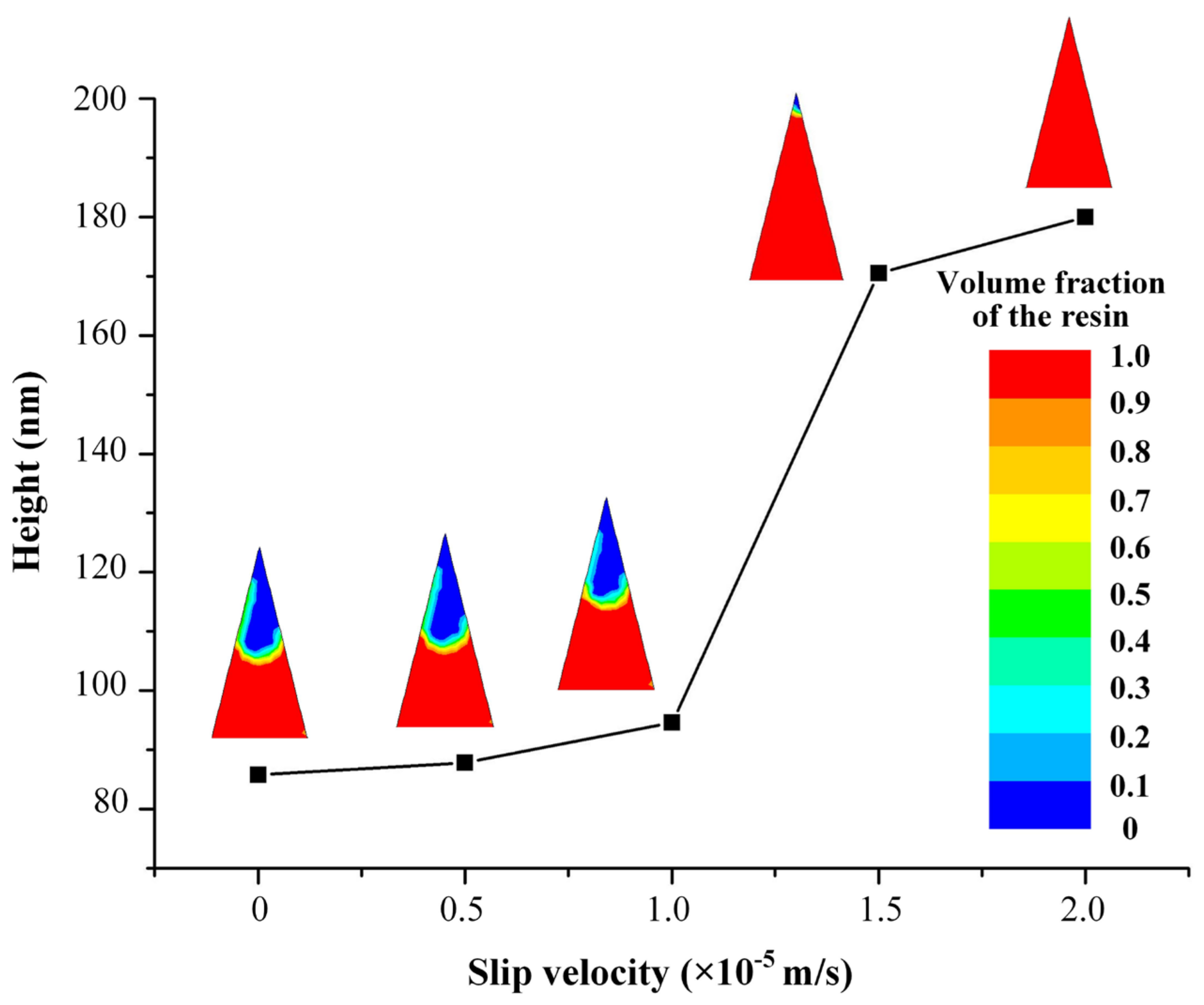
3.3. Effect of Slip Velocity
Figure 13 showed the effect of slip velocity on the filling height of the moth-eye nanostructure. In order to ensure one single variable, the slip positions were all on the mold side only, the inlet velocity was 1.0 × 10
−5 m/s, the resin viscosity was 0.1 Pa·s and the resin thickness was 200 nm, respectively. It could be observed that the filling height increased as the slip velocity increased. However, the influence of slip velocity was not significant when the slip velocity was less than 1.0 × 10
−5 m/s, while the filling height was significantly affected when the slip velocity was larger than 1.0 × 10
−5 m/s. The reason for this phenomenon was that the filling height was affected by the slip velocity and resin inlet velocity simultaneously, and the filling height was mainly affected by the resin inlet velocity when the slip velocity was small while it was mainly affected by the slip velocity when the slip velocity was larger than a certain threshold [
32,
33].
Figure 14 showed the filling evolution process with different slip velocity, which was 0 m/s, 1.0 × 10
−5 m/s and 2.0 × 10
−5 m/s, respectively. It was observed that the flow velocity near the mold side increased as the slip velocity increased so that more resin could flow into the mold cavity under the same conditions, thereby obtaining a larger filling height.
4. Conclusions
A CFD simulation model was established to investigate the resin filling behavior during the UV-NIL process of the moth-eye nanostructure, where the effect of boundary slip was considered. By comparison with the experimental results, a good consistency was found, indicating that the simulation model could be used to analyze the resin filling behavior in the UV-NIL process of the moth-eye nanostructure.
Based on the proposed model, the effects of process parameters on filling behavior were analyzed, including resin viscosity, inlet velocity and resin thickness. It was found that the inlet velocity showed a more significant effect on filling height than resin viscosity and thickness. Therefore, choosing a reasonable speed was quite important during the UV-NIL of the moth-eye nanostructure, taking into account the forming accuracy and efficiency comprehensively, which could provide guidance for the UV-NIL experiments of the moth-eye nanostructure.
Besides, the effects of boundary conditions on the mold filling behavior of moth-eye nanostructure were also investigated. It was found that the slip position showed a significant influence on the resin filling behavior and the forming height was 87.6 nm, 73.2 nm, 54.3 nm and 180 nm with no-slip on both the mold and the substrate, slip on both the mold and the substrate, slip on the substrate only, and slip on the mold only, respectively. Moreover, the filling height was affected by the slip velocity and resin inlet velocity simultaneously, and the filling height was mainly affected by the inlet velocity when the slip velocity was small while it was mainly affected by the slip velocity when the slip velocity was larger than a certain threshold. The results could provide guidance for the regulation of solid–liquid interface properties.
Author Contributions
Drafting the work, Y.C., X.W.; The acquisition and analysis of data for the work, C.Z., J.W. and Z.S. All authors have read and agreed to the published version of the manuscript.
Funding
This research received no external funding.
Institutional Review Board Statement
Not applicable.
Informed Consent Statement
Not applicable.
Data Availability Statement
Data is contained within the article.
Acknowledgments
The authors would like to thank the Natural Science Foundation of Jiangsu Province (BK20190202), the China Postdoctoral Science Foundation (2021M691926), the Research Project of State Key Laboratory of Mechanical System and Vibration (MSV202102), the Shandong Provincial Natural Science Foundation (ZR2019BEE062) and Young Scholars Program of Shandong University.
Conflicts of Interest
The authors declare no competing financial interests.
References
- Chen, H.; Lan, Y.F.; Tsai, C.Y.; Wu, S.T. Low-voltage blue-phase liquid crystal display with diamond-shape electrodes. Liq. Cryst. 2016, 44, 1124–1130. [Google Scholar] [CrossRef]
- Liu, Y.; Lai, J.; Li, X.; Xiang, Y.; Li, J.; Zhou, J. A quantum dot array for enhanced tricolor liquid-crystal display. IEEE Photonics J. 2017, 9, 1–7. [Google Scholar] [CrossRef]
- Yoshikawa, K.; Kawasaki, H.; Yoshida, W.; Irie, T.; Konishi, K.; Nakano, K.; Uto, T.; Adachi, D.; Kanematsu, M.; Uzu, H.; et al. Silicon heterojunction solar cell with interdigitated back contacts for a photoconversion efficiency over 26%. Nat. Energy 2017, 2, 17032. [Google Scholar] [CrossRef]
- Zheng, Z.; Awartani, O.M.; Gautam, B.; Liu, D.; Qin, Y.; Li, W.; Bataller, A.; Gundogdu, K.; Ade, H.; Hou, J. Efficient charge transfer and fine-tuned energy level alignment in a THF-processed fullerene-free organic solar cell with 11.3% efficiency. Adv. Mater. 2017, 29, 1604241. [Google Scholar] [CrossRef] [PubMed]
- Goossens, S.; Navickaite, G.; Monasterio, C.; Gupta, S.; Piqueras, J.J.; Pérez, R.; Burwell, G.; Nikitskiy, I.; Lasanta, T.; Galán, T.; et al. Broadband image sensor array based on graphene–CMOS integration. Nat. Photonics 2017, 11, 366–371. [Google Scholar] [CrossRef]
- Vukusic, P.; Sambles, J.R. Photonic structures in biology. Nat. Cell Biol. 2003, 424, 852–855. [Google Scholar] [CrossRef] [PubMed]
- Zhang, C.; Yi, P.; Peng, L.; Ni, J. Optimization and continuous fabrication of moth-eye nanostructure array on flexible polyethylene terephthalate substrate towards broadband antireflection. Appl. Opt. 2017, 56, 2901–2907. [Google Scholar] [CrossRef] [PubMed]
- Zhang, C.; Yi, P.; Peng, L.; Lai, X.; Ni, J. Fabrication of moth-eye nanostructure arrays using roll-to-roll uv-nanoimprint lithography with an anodic aluminum oxide mold. IEEE Trans. Nanotechnol. 2015, 14, 1127–1137. [Google Scholar] [CrossRef]
- Brousseau, E.B.; Dimov, S.S.; Pham, D. Some recent advances in multi-material micro-and nano-manufacturing. Int. J. Adv. Manuf. Technol. 2009, 47, 161–180. [Google Scholar] [CrossRef]
- Leveder, T.; Landis, S.; Davoust, L.; Chaix, N. Flow property measurements for nanoimprint simulation. Microelectron. Eng. 2007, 84, 928–931. [Google Scholar] [CrossRef] [Green Version]
- Reddy, S.; Bonnecaze, R.T. Simulation of fluid flow in the step and flash imprint lithography process. Microelectron. Eng. 2005, 82, 60–70. [Google Scholar] [CrossRef]
- Yanagishita, T.; Kondo, T.; Masuda, H. Preparation of renewable antireflection moth-eye surfaces by nanoimprinting using anodic porous alumina molds. J. Vac. Sci. Technol. B 2018, 36, 031802. [Google Scholar] [CrossRef] [Green Version]
- Sun, J.; Wang, X.; Wu, J.; Jiang, C.; Shen, J.; Cooper, M.A.; Zheng, X.; Liu, Y.; Yang, Z.; Wu, D. Biomimetic moth-eye nanofabrication: Enhanced antireflection with superior self-cleaning characteristic. Sci. Rep. 2018, 8, 1–10. [Google Scholar] [CrossRef] [PubMed] [Green Version]
- Wang, J.; Li, M.; Qiu, J.; Zhou, Y. Filling angle and its effect on filling process in roll-to-roll ultraviolet imprint lithography. J. Micromech. Microeng. 2018, 28, 035011. [Google Scholar] [CrossRef]
- Jain, A.; Spann, A.; Bonnecaze, R.T. Effect of droplet size, droplet placement, and gas dissolution on throughput and defect rate in UV nanoimprint lithography. J. Vac. Sci. Technol. B 2017, 35, 011602. [Google Scholar] [CrossRef]
- Kim, K.-D.; Kwon, H.-J.; Choi, D.-G.; Jeong, J.-H.; Lee, E.-S. Resist flow behavior in ultraviolet nanoimprint lithography as a function of contact angle with stamp and substrate. Jpn. J. Appl. Phys. 2008, 47, 8648–8651. [Google Scholar] [CrossRef]
- Peng, L.; Yi, P.; Wu, H.; Lai, X. Study on bubble defects in roll-to-roll UV imprinting process for micropyramid arrays II: Numerical study. J. Vac. Sci. Technol. B 2016, 34, 051203. [Google Scholar] [CrossRef]
- Wu, H.; Yi, P.; Peng, L.; Lai, X. Study on bubble defects in roll-to-roll UV imprinting process for micropyramid arrays. I. Experiments. J. Vac. Sci. Technol. B 2016, 34, 021201. [Google Scholar] [CrossRef]
- Tian, H.; Shao, J.; Ding, Y.; Li, X.; Li, X. Numerical studies of electrically induced pattern formation by coupling liquid dielectrophoresis and two-phase flow. Electrophoresis 2011, 32, 2245–2252. [Google Scholar] [CrossRef] [PubMed]
- Nagaoka, Y.; Suzuki, R.; Hiroshima, H.; Nishikura, N.; Kawata, H.; Yamazaki, N.; Iwasaki, T.; Hirai, Y. Simulation of resist filling properties under condensable gas ambient in ultraviolet nanoimprint lithography. Jpn. J. Appl. Phys. 2012, 51, 06FJ07. [Google Scholar] [CrossRef]
- Shibata, M.; Horiba, A.; Nagaoka, Y.; Kawata, H.; Yasuda, M.; Hirai, Y. Process-simulation system for UV-nanoimprint lithography. J. Vac. Sci. Technol. B 2010, 28, C6M108. [Google Scholar] [CrossRef]
- Ye, H.; Zhang, Q.; Shen, L.; Li, M. Bubble defect control in low-cost roll-to-roll ultraviolet imprint lithography. Micro Nano Lett. 2014, 9, 28–30. [Google Scholar] [CrossRef]
- Ali, J.; Kim, H.; Cheang, U.K.; Kim, M.J. Micro-PIV measurements of flows induced by rotating microparticles near a boundary. Microfluid. Nanofluid. 2016, 20, 131. [Google Scholar] [CrossRef]
- Cross, B.; Barraud, C.; Picard, C.; Léger, L.; Restagno, F.; Charlaix, É. Wall slip of complex fluids: Interfacial friction versus slip length. Phys. Rev. Fluids 2018, 3, 062001. [Google Scholar] [CrossRef] [Green Version]
- Morihara, D.; Nagaoka, Y.; Hiroshima, H.; Hirai, Y. Numerical study on bubble trapping in UV nanoimprint lithography. J. Vac. Sci. Technol. B 2009, 27, 2866. [Google Scholar] [CrossRef]
- Jain, A.; Bonnecaze, R.T. Fluid management in roll-to-roll nanoimprint lithography. J. Appl. Phys. 2013, 113, 234511. [Google Scholar] [CrossRef]
- Zhang, C.; Zhu, Y.; Yi, P.; Peng, L.; Lai, X. Fabrication of flexible silver nanowire conductive films and transmittance improvement based on moth-eye nanostructure array. J. Micromech. Microeng. 2017, 27, 075010. [Google Scholar] [CrossRef]
- Rashidi, S.; Akar, S.; Bovand, M.; Ellahi, R. Volume of fluid model to simulate the nanofluid flow and entropy generation in a single slope solar still. Renew. Energy 2018, 115, 400–410. [Google Scholar] [CrossRef]
- Wu, W.; Hu, C.; Hu, J.; Yuan, S.; Zhang, R. Jet cooling characteristics for ball bearings using the VOF multiphase model. Int. J. Therm. Sci. 2017, 116, 150–158. [Google Scholar] [CrossRef]
- Hiroshima, H.; Suzuki, K. Study on change in UV nanoimprint pattern by altering shrinkage of UV curable resin. Jpn. J. Appl. Phys. 2011, 50, 06GK09. [Google Scholar] [CrossRef]
- Horiba, A.; Yasuda, M.; Kawata, H.; Okada, M.; Matsui, S.; Hirai, Y. Impact of resist shrinkage and its correction in nanoimprint lithography. Jpn. J. Appl. Phys. 2012, 51, 06FJ06. [Google Scholar] [CrossRef]
- Donggang, Y.; Byung, K. Simulation of the filling process in micro channels for polymeric materials. J. Micromech. Microeng. 2002, 12, 604. [Google Scholar]
- Arabpour, A.; Karimipour, A.; Toghraie, D. The study of heat transfer and laminar flow of kerosene/multi-walled carbon nanotubes (MWCNTs) nanofluid in the microchannel heat sink with slip boundary condition. J. Therm. Anal. Calorim. 2017, 131, 1553–1566. [Google Scholar] [CrossRef]
| Publisher’s Note: MDPI stays neutral with regard to jurisdictional claims in published maps and institutional affiliations. |
© 2021 by the authors. Licensee MDPI, Basel, Switzerland. This article is an open access article distributed under the terms and conditions of the Creative Commons Attribution (CC BY) license (https://creativecommons.org/licenses/by/4.0/).


