1. Introduction
As part of their research and development work, the authors sought answers to the question of how voltage sags affect the continuous operation and lifespan of single-phase industrial robots with a lifting capacity of up to 10 kg. The research was conducted in six group ranges of time and sag depth from 0% to 99% with a 1% supply power surge. Based on the results of the experimental test, the effects of voltage sags—the most common form of disturbance to power quality—on the continuous operation of industrial robots was analysed, taking into account the likelihood of the destruction of the robots. The authors juxtaposed the test results with the SEMI F47/ITIC characteristics that revealed destructive conditions for power receivers (20–500 ms at voltage dips of over 70%), defined as being free from damage. Disturbances were also identified in the operation of the automation systems, including error loggers, which, due to collapse, fail to record changes in the position of the robot arm in space (distorted position of the encoders), which may result in unforeseen consequences of permanent damage to the unit or its surroundings, which is new knowledge in the discipline. Taking into account the occurrence of destructive conditions, a matrix was developed for industrial robotic systems in relation to standard PN-EN 61000-2-4 [
1].
Technological process equipment manufacturers often refer to relevant standards, declaring that their equipment can operate in a disturbed environment [
2,
3]. However, at present many devices are made up of numerous complex components, such as control systems, manipulators and actuating elements. This often misleads potential users when determining the resistance class and emission of the device as a whole. Interpretive errors are due to the fact that manufacturers declare that the devices comply with the standard, while not all of the components can operate in a given environment with the same degree of disturbance [
4,
5].
The literature often cites device resistance classifications such as TIC/SEMI F47 and CBEMA voltage tolerance curves. At this point, it should be emphasised that, although the topic is extremely important, only a small number of publications describe the problem of the source itself, drawing solutions as well. Unfortunately, this state of affairs results from the nature of the involvement of research groups in this area, which usually work for the manufacturer of robots or peripheral equipment (such as grippers and actuators—including welding, detection, laser, etc.), which is associated with a total ban on disclosing information about their results, including identified problems. There is a perspective that the increasing presence of robotic equipment in the laboratory infrastructure allows for the conclusion that problems resulting from disturbances in their work (especially those leading to the destruction of the robot itself or its periphery) will raise questions and the inquisitiveness of the scientific operator, which will allow for further research into their formation. The subject curiosity and scientific inquisitiveness also lie at the basis of research work aimed at finding answers to whether and to what extent one of the many disturbances in energy quality in the form of voltage dips may damage the electrical receiver (in this case single-phase industrial robots). As a result of the research work carried out and the analysis of their results, not only was the negative impact of stress dips on the durability of industrial robots confirmed as significantly broader than expected, but it was also identified that the disturbances leading to this damage were found in areas defined as free from such conditions. In this context, the authors decided to make the discovery public, hoping that it would trigger a wide-ranging discussion on the need to continue research in this area, taking into account all types of electrical energy disturbances, including those in the group of three-phase robots.
It is also highly probable that the current ITIC/SEMI F47 resistance curves do not reflect problematic phenomena leading to receiver damage, which results from significant progress in the area design and the production of power supply systems, power electronics or automation and control. This progress involves many problematic phenomena that were not taken into account at the time when the above-mentioned characteristics were designed, which, as the authors showed, increased the risk of destructive disturbances in the area. Thus far, these risks been defined as possibly causing electrical energy disturbances, leading to disturbances in the operation of the electrical receiver, but never resulting in damage to the electrical receiver.
The above problems and the increasing incidence of misdiagnosed abnormal conditions in industrial robots (service requests based on incorrect logging of a disturbance source) focused research efforts on looking for incidents with incorrect logging by the robot automation system and determining their effects on the risk of damage to the robot, as well as confirming the occurrence of destructive conditions in areas defined by ITIC/SEMI F47 and CBEMA characteristics as being free from such disturbances. In addition, the authors proposed the use of a matrix for the environmental classification of industrial robots and their equipment in order to select a robot according to the working conditions and, more importantly, in order to choose electrical/power equipment that would compensate for the negative effects of voltage sags on the continuous operation or lifespan of the robotic cell.
As part of the authors’ research work, which is presented in earlier studies [
6], the project team proposed an environmental classification matrix (
Appendix A) for the continuous operation of single-phase industrial robots with a lifting capacity of up to 10 kg. This results in the superiority of the process functionalities and features of the robot and enable the division of the robots into the following three classes:
Class I—required continuous operation (fully automatic process) for the correct implementation of the manufacturing process in which the robot is installed;
Class II—required stability of operation in the process in which the robot is installed (operation in interrupted cycles where there is a pause between cycles and where another non-automated operation occurs between cycles—a semi-automatic process);
Class III—required stability during the implementation cycle (individual process in which the robot performs a specific action throughout the non-automatic process–robotic technology islands).
Consequently, when used in combination with the electromagnetic resistance classes, electrical equipment that limits or completely compensates for voltage sags and other disturbances in power quality can be properly selected. In relation to the work carried out, the results of which are presented in this article, the classification matrix is restricted to merely assess quality disturbances in the form of voltage sags (as these are the most common disturbances in power quality).
For the first environmental class, equipment was assigned with the highest level of assurance that the process would be maintained in continuous operation despite the occurrence of deep voltage sags and even micro power outages, including standby power and accessories in the form of voltage conditioners such as AVR (Automatic Voltage Regulator), DVR (Dynamic Voltage Restorer), DySC (Dynamic Voltage Sag Corrector), UPS online (Uninterruptible Power Supply), cross-emission reduction in the robot environment, and both passive and active filters.
For the second class, the following two subgroups can be distinguished:
Group 1—which allows for power outages that do not cause significant problems in the manufacturing process, requiring at least emergency power (short-term support) and accessories in the form of voltage conditioners such as AVR, DVR, DySC, Online UPS, cross-emission reduction in the robot environment, and both passive and active filters;
Group 2—which allows for incidents that cause robot automation to reset cyclically, while the manufacturing process permits such incidents.
No provision for auxiliary equipment is made for the final environmental class (Class 3), which by nature of the process allows the robots to be automatically reset on the production line without the consequences of interrupting the process or having to stop the entire manufacturing process. However, due to the potential for serious disturbances in logging errors and information regarding the robot interior equipment condition, it is recommended to introduce a position measurement support system based on the external source (e.g., passive optical system) to additionally control the condition of the arm and modulators during and after resetting.
The full classification matrix is presented in
Appendix A of this publication.
The research confirmed the occurrence of conditions which eventually lead to damaging a robot/its surroundings or to a health- or life-threatening situation for operators and/or technical services, although, in theory and in accordance with the normative guidelines and the ITIC/SEMI F47 and CBEMA characteristics, the occurrence of such a disturbance should not lead to the destruction of the receiver. Thus, the research identified a major defect in the certification and testing system of power receivers for Class 3 electromagnetic resistance (commissioning a receiver which is damaged despite the proven resistance to destruction in the acceptance tests), which is characteristic of receivers operating in highly disturbed environments.
The literature on the subject, although not very extensive (which is due to the specific character of research work conducted by research groups contracted by international corporations that are industrial robot manufacturers and the nature of their extremely strict confidentiality clauses) clearly indicates the occurrence of problems in maintaining the operating parameters (e.g., peripheral components, such as manipulators, external sensory systems, etc.) as a result of voltage sags. There is a common phenomenon resulting from the differences in the classes of electromagnetic resistance between a robot and its equipment [
7]. The authors of the article “Effects of Voltage Dips on Robotic Grasping” discuss the effects of disturbances in power quality on robot performance, with particular emphasis on the effects of voltage sags on the robot supply system and auxiliary equipment from the point of view of the end user/operator. In the opinion of the authors, it is reasonable to conduct independent research in this field and on its basis build new standards for testing and commissioning receivers, such as industrial robots. The current normative guidance-based procedures treat peripherals and robots independently, which seems to be a flawed approach, as in extreme cases this can lead to the repair of a robot being refused due to the use of different EMC resistance classes. As this article and the cited publications show, this is an extremely important problem in terms of the effective exploitation of dynamically developing robotic environments, which justifies the undertaking of further work on the cumulative effects (not only voltage sags) of disturbances to power quality on the lifespan and stability operation of high power three-phase industrial robots.
2. Materials and Methods
The specification of robotic positions in the context of power conditions for industrial robots should be considered individually for the applied robot architecture. During the research, the authors considered several different systems, presented below, as the article is focused on the problem of the power supply conditions of a single robotic socket dedicated to precision works with the use of single-phase robots with a lifting capacity of up to 10 kg [
8].
Circuits with a single-phase robot for which the impact of disturbances in the power-quality parameters of electricity were considered:
a single robotic station,
a station connecting several keypads to one controller,
a station equipped with one controller but with each manipulator having its own automation of drive control,
synchronised single robotic stations, each equipped with a separate controller which uses coordinated programming.
It should be noted here that all incidents from the power supply network from the power utility company that disrupted the operation of a single robotic station were recorded in cases of the combined work of many manipulators. In the case of an internal power supply network in which there are many robotic positions, the phenomenon of the propagation of disturbances from one robotic station to the other was also identified. In view of the above, the authors of the article presented the problem of the impact of electricity of poor quality, and, more specifically, the occurrence of voltage dips on robotic sockets in the example of individual robot positions of various companies.
In the case of a common point of connecting consumers to distribution networks, distribution system operators (DSO) are obliged to ensure a certain quality of electrical supply in accordance with the applicable requirements [
9]. In Poland, this is the Regulation of the Minister of Economy of 4 May 2007 on detailed conditions for the operation of the power system (RGM), which is based on the old version of the EN 50160 standard-supply voltage parameters for public electricity grids. The current version of EN 50160 [
10], as amended, differs in many ways from RGM. Whereas, in the considerations of powering robotic sockets in industrial production lines, power supply parameters should be considered in accordance with IEC 61000-2-4 [
1] electromagnetic compatibility (EMC)-part 2–4: environment-compatibility levels in industrial plants for low-frequency conducted disturbances. According to the aforementioned documents, the quality parameters that are accepted by the devices may significantly differ from those required by the arrangement of computer equipment, along with their progress in miniaturisation [
11,
12,
13]. Disturbances in the supply voltage outside the area specified by the standards may have the following effects [
3,
6,
14]:
disruption of devices,
damage to sensitive data processing devices controlling processes,
speed changes of drive units,
data processing and measurement errors,
control errors,
overheating of motors, capacitors and transformers,
flickering of light.
The effects cited are only a small percentage of the unfavourable phenomena. Bear in mind that even during the normal operation of the power system (no emergency states), there are many factors affecting the operation time and the possibility of destroying sensitive receivers. In the case of industrial plants, there are also additional phenomena caused by the receivers themselves, such as start-ups of drives, switching on and off of high-power devices (dips, overvoltages) and emergency states [
15,
16]. With increasing frequency, industrial plants use devices with high sensitivity, such as:
control systems of production processes,
computers and servers,
telecommunications devices,
protection and security systems,
automation and robotics devices,
HMI systems,
diagnostic and health equipment,
cash registers and vending machines,
electronic clocks.
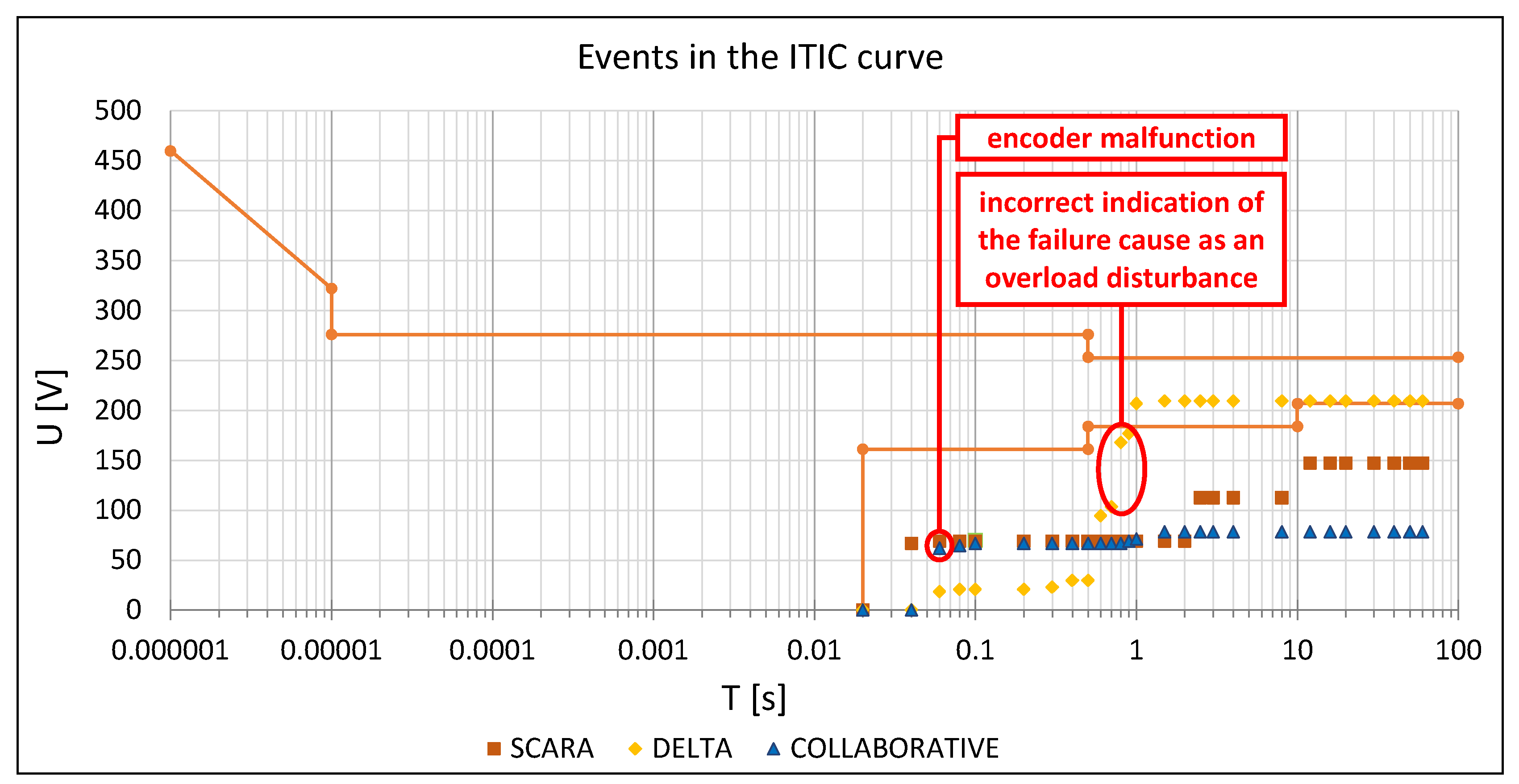
Significant events for the continuity of work in industrial plants are voltage dips and increases. In the case of a decrease in the voltage amplitude, there may be various causes, e.g., a sudden increase in load caused by the start-up of high-power receivers, such as motors, blowers and heating systems as well as emergency states and short circuits [
17,
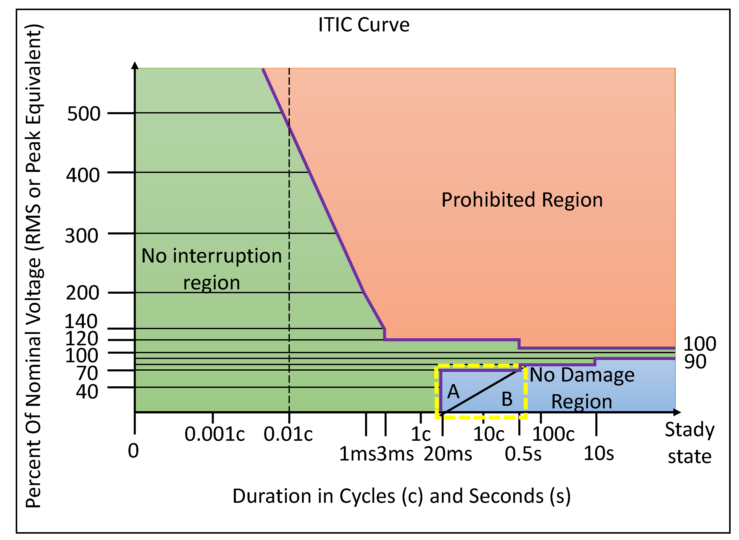
18]. The source of such an event may be the national power grid, but in the vast majority of cases, it is the recipient itself. A reduction of the effective voltage value causes a disturbance in the operation of devices that are not equipped with energy stores, such as capacitors or accumulators. The next type of event is an increase of voltage amplitude—in this case, the source may be a sudden reduction of the load, damage to the neutral conductor, or atmospheric discharges. Permissible changes in the voltage of the computer hardware as a function of time are presented on the ITIC curve in
Figure 1. The area of voltage changes in which the devices work correctly is highlighted in green, and it should be noted that short increases and voltage dips are permitted. The prohibited area is marked in orange; this condition causes faster wear and may destroy the device in the longer term. The blue area is marked as an area where theoretically there is no risk of damage to the device, but it can cause its emergency operation. In
Figure 1, a yellow dotted area is marked as an area that is particularly susceptible to disturbances, and at the same time, it is significant from the point of view of the stability of industrial robots and the number of disturbances and interruptions in their work. This area is the main point of interest due to the increase in the number of power electronics devices in power grids which causes frequent exceedances of the ranges specified in the standards, thus generating many operational problems which, in the search for the optimisation of industrial processes using robotic tools, constitute a significant technological problem [
19]. The current standard guidelines for tests permitting the operation of industrial robots (especially in the field of electromagnetic compatibility) need to be extended because they do not guarantee the maintenance of reliability, stability and continuity of operation in environments with unstable power-supply parameters.
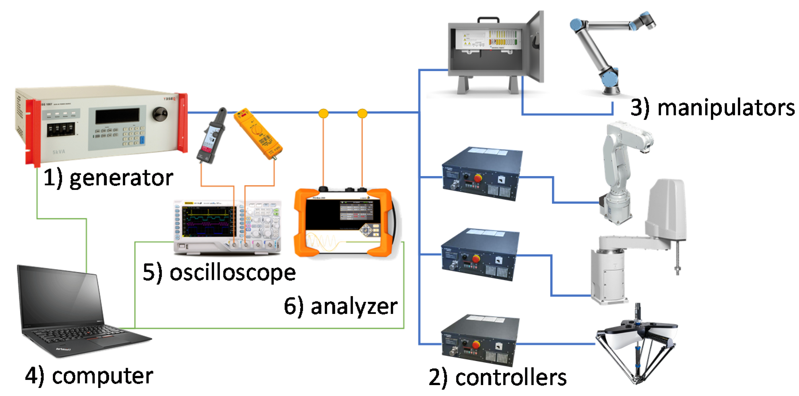
Initially, in the identification of the problem of improving power-supply conditions of single-phase industrial robots with a lifting capacity of up to 10 kg, a broad review of the prevailing literature was conducted, on the basis of which the ranges of disturbances and the conditions in which they occur were distinguished. On the basis of elaborated assumptions and the parameters of electromagnetic compatibility specified in the norms and other documents, the conditions or the occurrence of the dips phenomenon, including separation of unidentified states leading to the total disruption of the robotic unit operation, were then determined. Subsequently, experimental work was performed under laboratory conditions allowing the simulation of operating conditions and the acquisition of measurement data sets of voltage and other power parameters of the tested units. A diagram of the devices used to conduct the tests is presented in
Figure 2, followed by a brief description of the equipment.
The Teseq NSG 1007 series (Teseq, Luterbach, Switzerland) source which has high efficiency and a lightweight AC and DC power source, which includes high-performance power analysers;
Robotics manipulator controller;
Robotic socket (various manipulator variants);
PC with WIN 2110 generator software for sag design and RIGOL UltraScope registration software, MATLAB software for post-processing of collected results;
DS4014E oscilloscope (RIGOL Technologies, Co. Ltd. Beijing, China) with DP-200pro Pintek high-voltage differential probe–1600 Vpp;
The A. Eberle GmbH PQ-Box 200 mobile power quality network analyser (A. Eberle, Nürnberg, Germany).
The initial tests were mainly performed in a system with one controller and manipulator, and after verification of the impact on one nest, tests with several robots were launched.
During the study, disturbances in the form of sags were generated, and they were then recorded with the oscilloscope and the analysis of the quality of electricity. The messages of the automation of industrial robots were then read and correlated with the events.
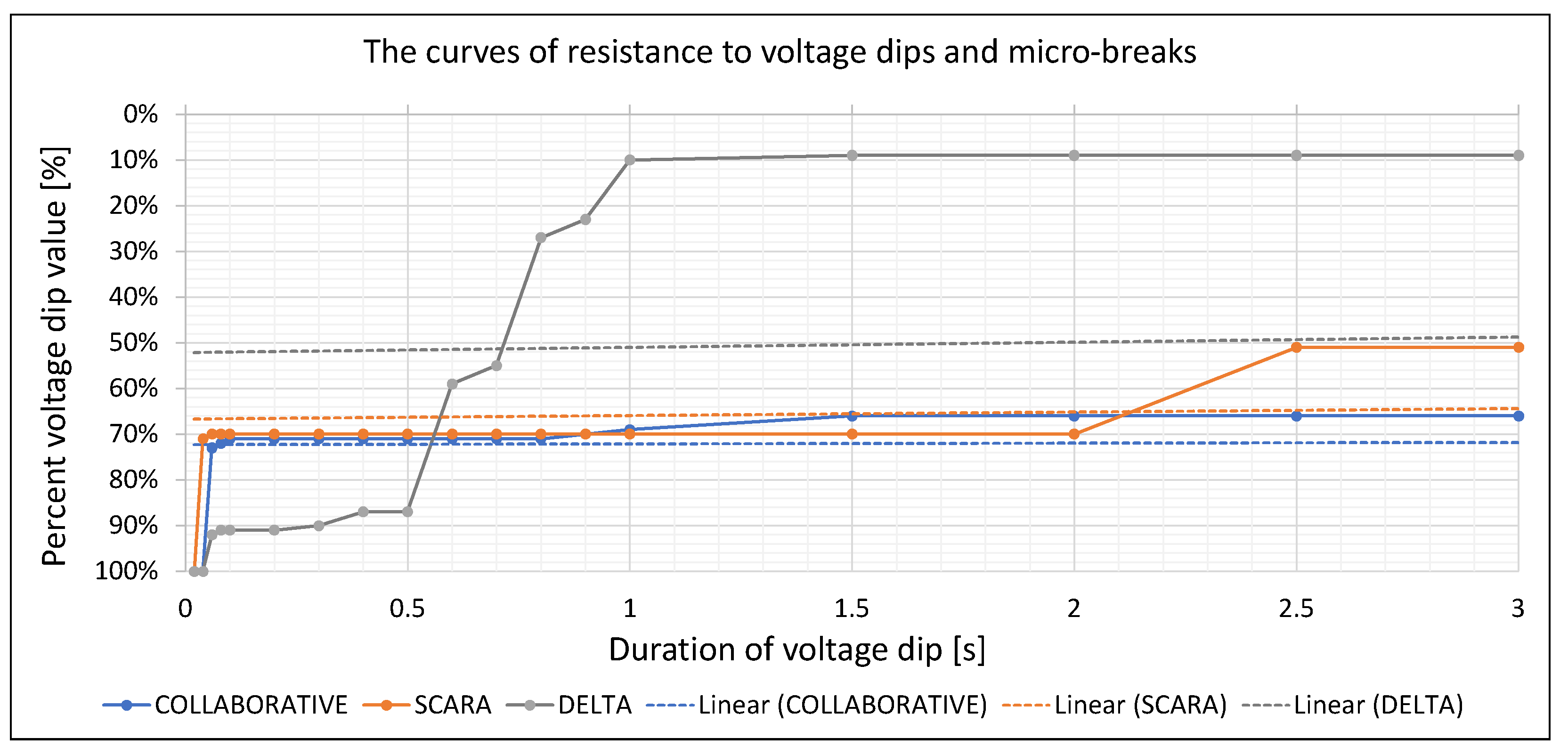
The research on the effect of voltage dips on the robotic units was conducted for the duration of the voltage dip, from 20 ms to 1 min. In order to simplify the analysis of test results, six time intervals were introduced, with individual time groups divided into four or five time intervals as follows:
group A—duration of the dip was 20–100 ms—5 intervals every 20 ms,
group B—duration of the dip was 200–500 ms—4 intervals every 100 ms,
group C—duration of the dip was 0.6–1 s—5 intervals every 0.1 s,
group D—duration of the dip was 1.5–3 s—4 intervals every 0.5 s,
group E—duration of the dip was 4–20 s—5 intervals every 4 s,
group F—duration of the dip was 30–60 s—4 intervals every 10 s.
Next, for each group, an iteration of one hundred measurements was performed where, in each subsequent iteration, the voltage dip was increased by 1% (0–99%).
The correctness of the test was verified using an oscilloscope and a power-quality analyser.
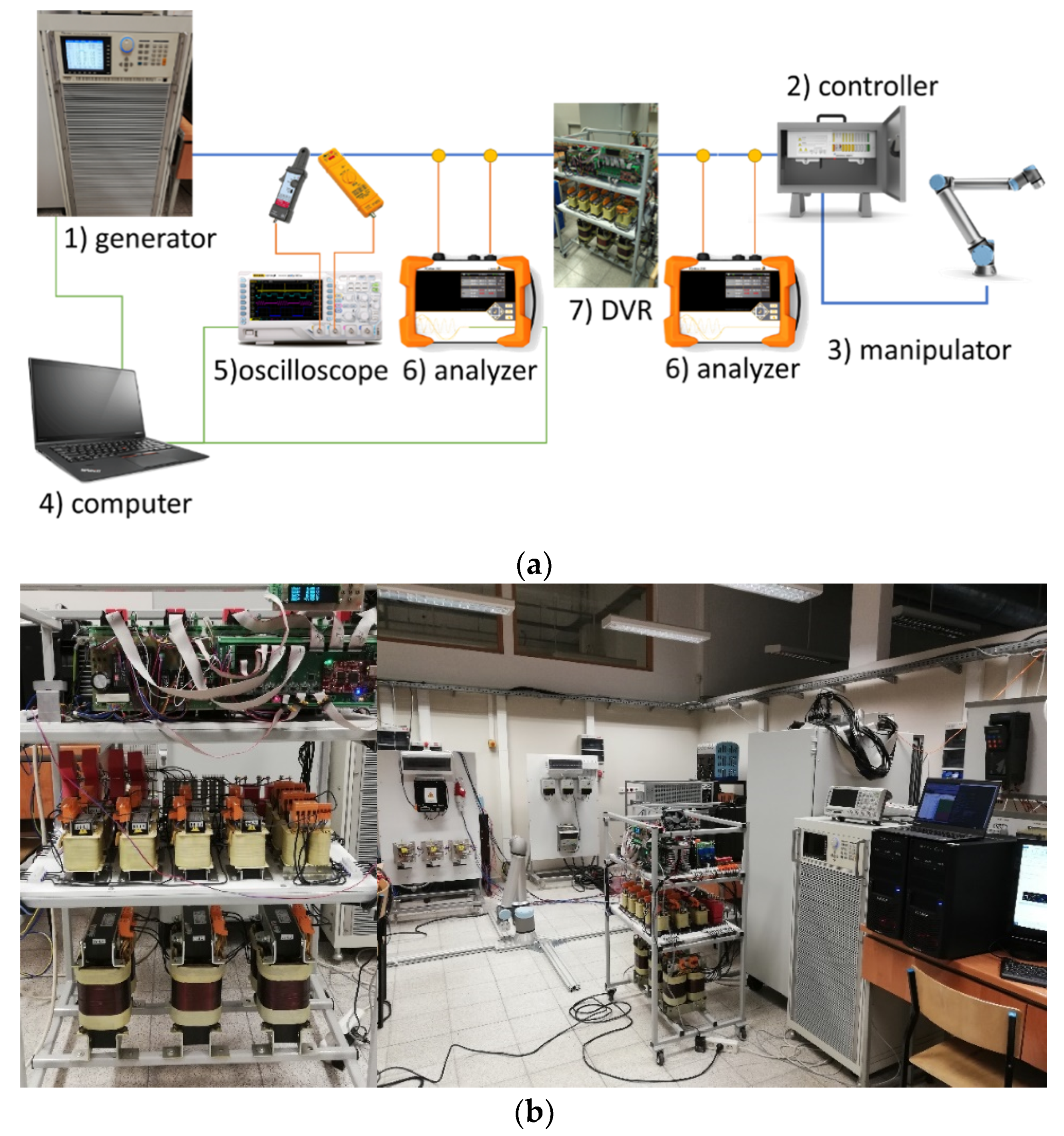
The authors decided to supplement the results obtained during the tests using the system presented in
Figure 2 with the results of the work using the selected and the most universal DVR voltage sag compilation system. The intention of the authors was to present confirmation of the effectiveness of the compilation process with the use of the DVR system. One of the authors’ earlier studies defined the problems of powering the industrial robots used in the welding process [
20]. At that time, the methods for limiting the impact of poor power quality on robotic sockets were presented. The authors of this study focused on the issue of reducing dynamic network states, particularly voltage dips. One method of conditioning the supply voltage is the use of dynamic voltage restoration (DVR) [
21]. This device is used to stabilise the supply voltage and eliminate the negative effects of voltage disturbances, not only those such as dips and voltage drops but also increases and, in particular cases, fluctuations. Devices of this type are used, in particular, in the security of production lines where the occurrence of any interruption in the operation of one critical device may result in interrupting the entire production process. Due to their design, these devices can be used in places where UPS type solutions cannot be used due to the size of the energy storage elements and the need to provide appropriate explosion zones and storage conditions. Subsequently, a study using one of the conditioners was presented in order to consider the possibility of reducing the impact of voltage dips on production lines.
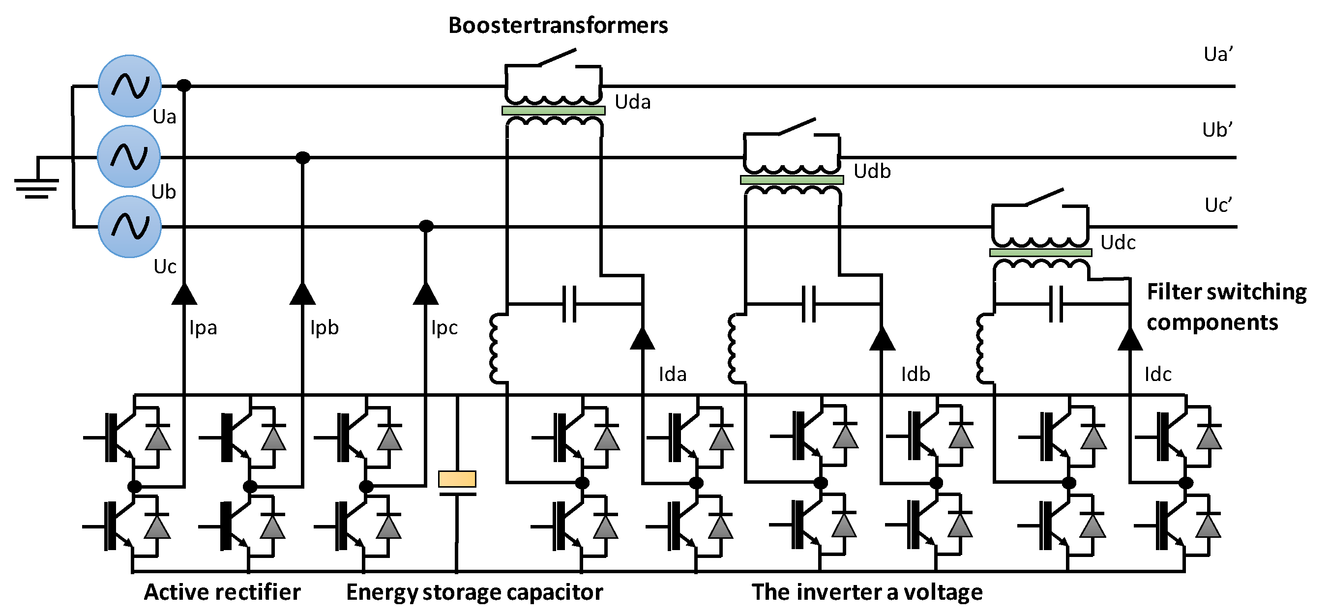
A general diagram of the device for improving power supply is presented in
Figure 3, while the schematic drawing of the measuring system is shown in
Figure 4. The measuring system differs from the system shown in
Figure 2 in the following elements: 1–high-power programmable AC source with transients–Chroma 61510, 6–two PQ-Box 200 analysers (Chroma Systems Solutions, Foothill Ranch, CA, USA) (at the generator output and at the input of the manipulator automation supply), and a 7–DVR dynamic voltage restorer (AGH University of Science and Technology, Kracow, Poland) (prototype research unit).
In the tested system, the power of the robot unit was connected to the secondary side of the DVR, while the primary side of the conditioner for single-phase tests (the Teseq NSG 1007 series generator) was used, and for the three-phase tests, the Chroma 61512 generator (Chroma Systems Solutions, Inc., Orange County, CA, USA) was used. Using the generator, dips were created that previously caused disturbances in the correct operation of the robot. In addition, a second electrical power-quality analyser was used in this system to compare the voltage at the DVR input and output.
As can be seen in the diagram, the DVR is connected in a series in the power supply circuit of the industrial robot. The DVR internal connection system consists of an active rectifier and three H inverters with a filter. The capacitor in the common DC bus acts as the energy storage for the additional voltage in the device [
22]. System synchronisation with the network is ensured by the reference current system. In addition, in the case of high currents caused by an excessive load or short circuit, the DVR is equipped with by-pass connectors, which protect it against damage. Operation of the device seems to be simple; however, the development of effective control algorithms and control and measurement devices is a difficult issue and is the subject of much research [
23].
4. Conclusions
As the results from the research presented in this article show, the process of designing robotic stations, including the selection of components of power electronics as well as assigning them a resistance class for disturbances, does not correspond to the current conditions in the power system. This is mainly caused by the increased number of disturbances introduced into the network by electrical power devices, such as inverters, and in recent years, also by renewable energy sources, which together with the development of semiconductor technologies have become common sources of disturbances.
At this point, it should be emphasised that the area of research into robots and their resilience is the domain of research teams who are manufacturing robotic units or scientists who are contracted by manufacturers, which significantly limits the development of knowledge in the field due to numerous corporate restrictions, including maintaining secrecy.
The authors indicate that the tests specified in the normative documents for production processes incorrectly classify the failure state in the group of events that do not affect damage to the receiver; these tests are aimed at confirming the resistance of the receiver to power quality disturbances, including the occurrence of voltage dips in combination with the erroneous interpretation of the type of disturbance on the receiver side. This is justified in order to introduce the recording of the voltage values in the receiver automation systems (especially industrial robots) and the correlation of their level with the current values because, as was established during the tests, the very registration of current overloads and voltages resulting from a voltage dip leads to erroneous conclusions. Therefore, it can be reasonably stated that the errors indicated during the immunity tests carried out on the basis of the currently applicable normative documents and guidelines, allow the placing on the market of devices that do not meet the requirements of resistance to energy quality disturbances (which is not the fault of the manufacturers themselves, as the tests are performed in accordance with normative requirements and a too narrow set of recorded parameters allows for errors in the interpretation and classification of disorders). Therefore, it is worth outlining the problem and investigating it at a deeper level in further research in order to also identify the discussed states in three-phase systems with higher power levels. Perhaps a simple solution to the problem would be the obligation to use undervoltage protection in power supply systems, which would allow for the rapid identification of the type of disturbance by correlating the voltage drop with the increase in current at the same time.
The collected quantity of measurement data from several types of industrial robots determines the need to broaden the base of the measurement results database to expand it with the addition of new models and other power systems. Bearing in mind the applicative character of the research results, it will be necessary to continue the work and constantly expand the measurement data resources for model improvement and the electromagnetic immunity characteristics of ITIC and SEMI F47 dedicated to industrial robots to work in the third class of EMC interferences. According to the presented results, the designers of production cycles, together with technicians, should take into account the requirements for feeding robotic sockets. The process class should define the requirements of the power-supply conditions with respect to the classification in normative documents as presented in this article.
The tests showed and confirmed the susceptibility of machines to failures within the range marked with a yellow frame on the ITCI characteristics in
Figure 1. In the next stages of their research, the authors of this text plan to conduct tests using various conditioners and analyse their impact in an environment with a high concentration of robotic sockets, as well as the impact of interference in the extended band up to 150 kHz. Initial research and its continuation are planned in cooperation with The Laboratory of Electrical Power Quality of AGH, which is the leading research unit in the country dealing with the subject of power quality.
After conducting another series of studies on the cooperation of a robotic station with a DVR and an industrial UPS, the authors will present a series of articles on the properties of cooperation of robotic stations with individual power conditioners.
The authors juxtaposed the test results with the SEMI F47/ITIC characteristics that revealed destructive conditions for power receivers (20 ms–500 ms at a voltage dip above 70%), in an area defined as being free from damage. Disturbances were also identified in the operation of the automation systems, including error loggers, which due to collapse, fail to record changes in the position of the robot arm in space (no registration of changes in the position of the encoders). This may result in unforeseen consequences of permanent damage to the unit or its environment, which is important for vacuum systems, which require special securing by additional electrical equipment. This is undoubtedly a significant discovery indicating the need to revise the current guidelines for researching the resistance of electrical receivers (including industrial robots and their equipment) to electricity disturbances.
It is worth emphasising that the use of compensation systems such as DVR, AVR, UPS, and DySc limit the identification of the source of the sags, although they actually compensate for disturbances in the form of voltage sags depending on the type of receiver (in this case, the robot type).


