Article

Characterization of MAO + Cu Composite Coatings on Aluminum Alloy

School of Materials Science and Chemical Engineering, Xi’an Technological University, Xi’an 710021, China
*
Authors to whom correspondence should be addressed.
Coatings 2021, 11(10), 1172; https://doi.org/10.3390/coatings11101172
Submission received: 9 August 2021 / Revised: 21 September 2021 / Accepted: 23 September 2021 / Published: 28 September 2021
(This article belongs to the Special Issue State-of-the-Art on Coatings Research in Asia)

Abstract

:
Novel composite coatings were fabricated on 6061 aluminum alloy substrates by two steps combining micro-arc oxidation (MAO) plus electroless copper plating (Cu). Different MAO + Cu composite coatings were compared. Cu continuously and evenly covered an aluminum oxide surface during processing thus changing the surface topography. The adhesion of MAO + Cu composite coating was tested by the pull-out method. The best adhesion strength of the composite coating can reach industrial requirements. The effects of the composite coatings on friction were investigated using a ball-on-disc test method. It is found that copper in composite coatings plays a lubricating effect during the wear process under dry sliding. Furthermore, the mechanisms by which the observed advantages were produced are discussed.

1. Introduction

Because of the high strength, low density, non-magnetic properties, thermal performance, and good formability, aluminum and its alloys are widely used in the aerospace and automotive industries [1,2,3]. Unfortunately, serious damage due to the low hardness and abrasion resistance of aluminum alloys limited the extensive application [4]. Pakiea uses laser beam treatment to introduce Ti and Fe onto the surface of AlMg5 aluminum alloy. It was found that an intermetallic phase rich in titanium and the aluminum compound phase significantly improves the mechanical properties of the coating [5]. Mohamad used anodizing technology to prepare a graphite-containing composite oxide film on AA2017-T4 aluminum alloy. It was found that the addition of graphite reduced the surface porosity of oxide film, improved the mechanical and tribological properties of oxide film, and extended the service life of the composite oxide film [1]. Sobolev uses Plasma electrolytic oxidation to perform surface treatment on 7075 aluminum alloy and found that the addition of oxide coating has significantly improved the corrosion resistance [6]. The surface modification treatment technology used in the above industrial production does not affect the aluminum alloy matrix and also gives the aluminum alloy surface better performance and improves its range of applications.
Adding other metals to the surface of aluminum alloys to decorate or improve the physical properties of aluminum has always been an area of active research and innovation. Electroless copper plating is a widely used surface modification treatment technology with a low production cost and a simple process. It can create a non-metallic surface with metallic characteristics and improve the electrical conductivity, thermal conductivity, ductility, and the gloss of the material [7,8,9]. Aluminum electrode potential (−1.67 V) is lower than the potential for the copper electrode (+0.34 V), and copper ions can be reduced to copper, but electroless copper plating is usually carried out in an alkaline environment. Aluminum belongs to amphoteric oxide and reacts under alkaline conditions [10]. Meanwhile, an oxide film is easily formed onto the surface of aluminum alloy, which will affect the bonding force between aluminum and the metal deposited on the aluminum surface [11,12]. Chemical methods of preparing galvanized zinc coating (−0.76 V), and then electroless copper plating, to avoid Al directly reacted with OH, can effectively enhance the bonding force. Chemical methods for preparing galvanized zinc coating, and then electroless copper plating, to avoid Al directly reacting with OH-, can effectively enhance the bonding force [13]. However, when the copper layer is broken by an external force, zinc and copper will form a galvanic reaction, which will accelerate the corrosion of the zinc layer and cause the copper layer to fall off.
The new environmentally friendly micro-arc oxidation (MAO) technology is used to prepare the oxide ceramic coating with good corrosion resistance. The replacement of the zinc coating by the ceramic coating will slow the shedding of the copper coating on the surface. MAO produces thick and hard ceramic coatings on the surface of threshold metals like Al, Mg, Ti, Zr, and their alloys, the MAO coating has a good adhesion on the substrate. The instantaneous high temperature forms the basic phases of α-Al2O3 and γ-Al2O3 on the aluminum alloy surface. MAO coatings surface is typically coarse and porous of the residual discharge channel [14,15,16,17]; however, the residual discharge channel can provide a better bonding force for the copper plating layer. The metal copper layer prepared by electroless copper plating technology can not only improve the decoration and beautification, but also improve the thermal conductivity and electrical conductivity of the alumina ceramic coating, thereby expanding the application field of aluminum alloy [18,19].

2. Experimental Details

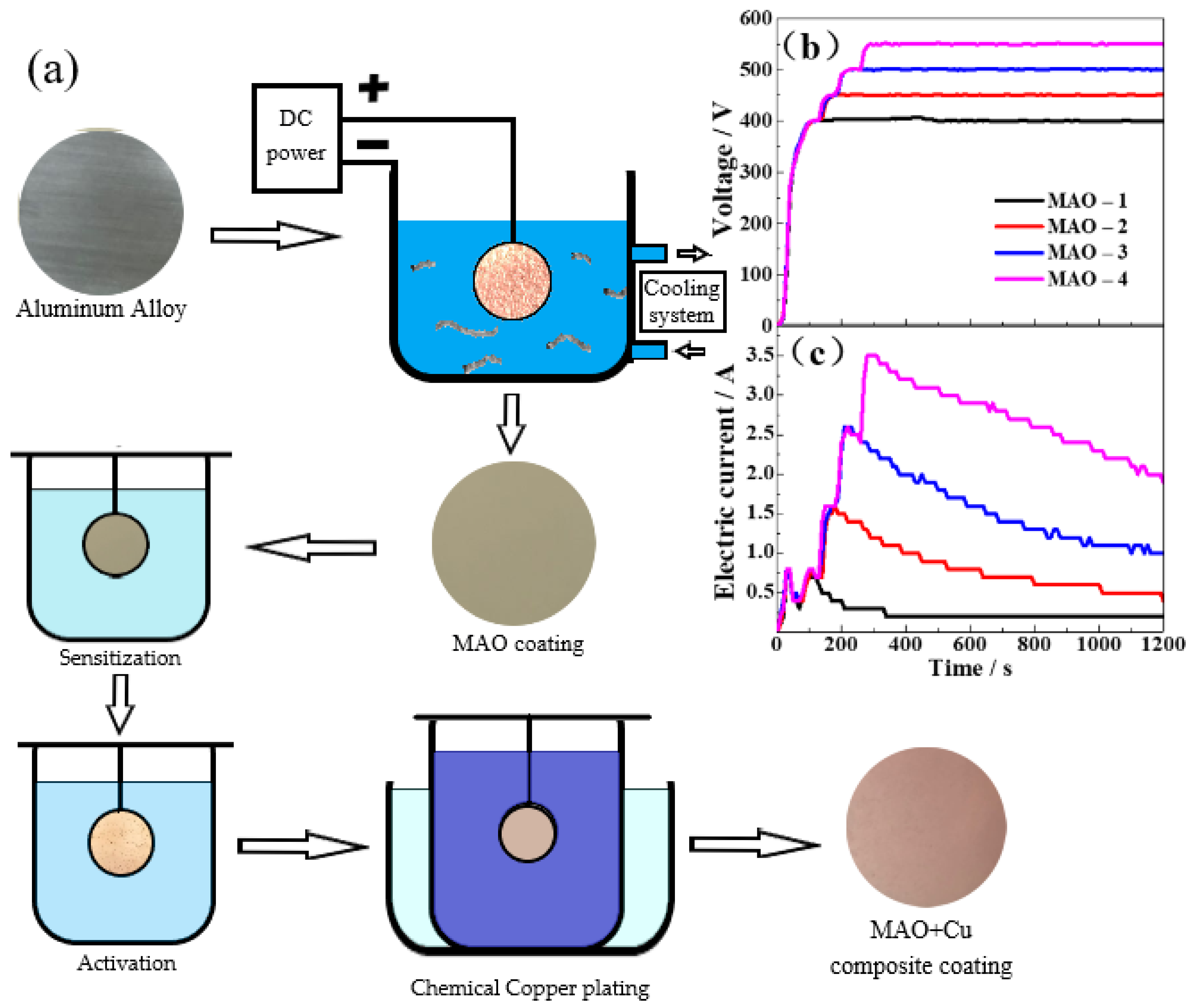
2.1. Material Preparation

The 6061-aluminum alloy is processed into a size of Ø 30 mm × 5 mm and ground with different grit emery paper (up to 1500 #) until a surface roughness of Ra ≈ 0.5 μm is achieved. Then, the samples were ultrasonically degreasing with acetone for 10 min at room temperature and then dried with hot air. MAO adopts the constant voltage mode. When the voltage reaches 280 V, the aluminum alloy specimen cylindrical arc boundaries appear to be tiny silvery white, and voltage increases lead to increased discharge phenomenon, the defects on the surface of the workpiece make the current distribution in an extremely unbalanced state, and the electrons preferentially converge to the defect micro-regions with lower resistance in the oxide layer, causing an arcing walk back and forth on the sample surface. The prepared MAO-1 ceramic coating has a working voltage of 400 V and a relatively low current. During the reaction, the surface of the ceramic coating remains only sporadic arcing. After completion of the reaction, samples were rinsed with deionized water, and then the MAO + Cu composite coating was prepared according to the process of Sensitization→Activation→Chemical copper plating. The main flow and process parameters of the experiment are shown in Table 1 and Figure 1. MAO-1, MAO-2, MAO-3, and MAO-4 are equal to the ceramic coating made in the operating voltage of 400 V, 450 V, 500 V, and 550 V.

2.2. Structure and Performance Characterization

The thickness of the MAO coats was measured by the TT-260 eddy current thickness gauge, and the average value of 15 random measurements is taken. The microstructure and morphology of the coatings were studied by scanning electron microscopy with energy dispersive X-ray spectroscopy (VEGA 3, TESCAN, Shanghai, China). The surface morphologies of the wear scars of the MAO + Cu composite coatings were characterized by a three-dimensional profilometer (Zegage, Zygo, CT, USA). The weight change was measured before and after copper plating with an electronic analytical balance (Yoke Instrument, Shanghai, China). The adhesion tester was 3 M 600-HC33 test tape according to ASTM D 3359-17 and GB/T 5270-2005 [20,21]. The adhesion test values were described in Figure 1. 5B means excellent adhesion, 0B means poor adhesion, and the other B values mean the different adhesion degree. Wear tests of the composite coatings and uncoated specimens were carried out by the ball-on-disc method under the dry sliding condition. The size of the friction pair was GCr15 steel ball with a diameter of 6 mm, the load of 200 g, and a speed of 200 r/min. The friction radius was 5 mm and the wear time was 10 min (HT-1000 wear tester, Lanzhou Zhongke Kaihua Technology Development, Lanzhou, China). The Vickers micro-hardness of coatings was measured by a micro Vickers hardness tester (402 MVD, WOLRERT, Shanghai, China) with a load of 200 g and a hold time of 10 s.

3. Results and Discussion

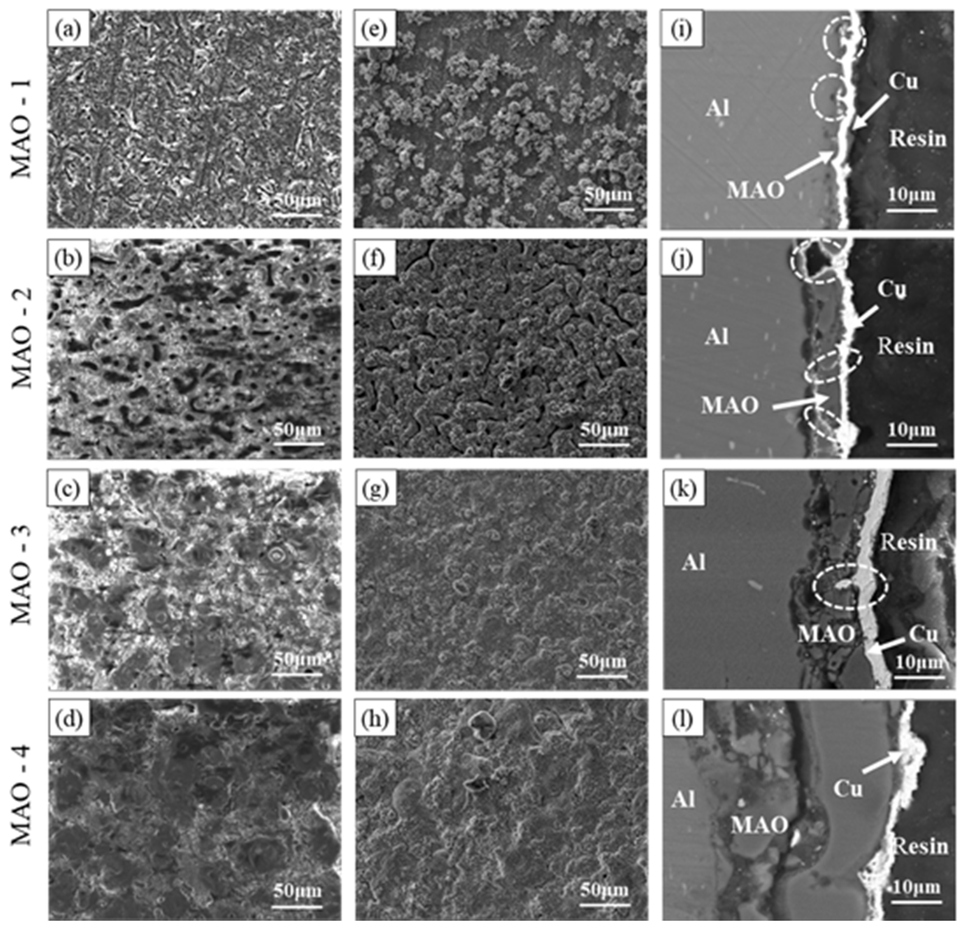
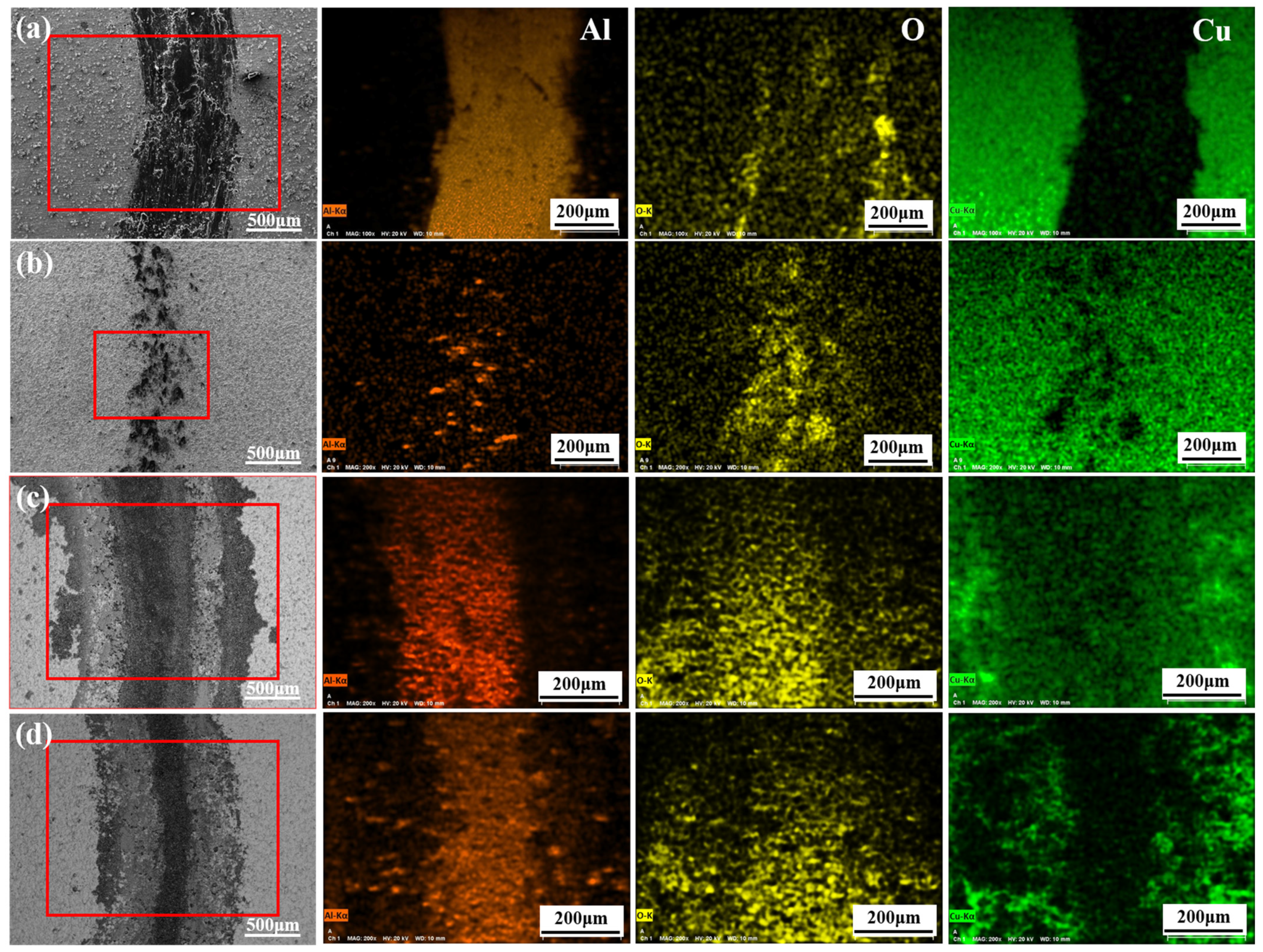
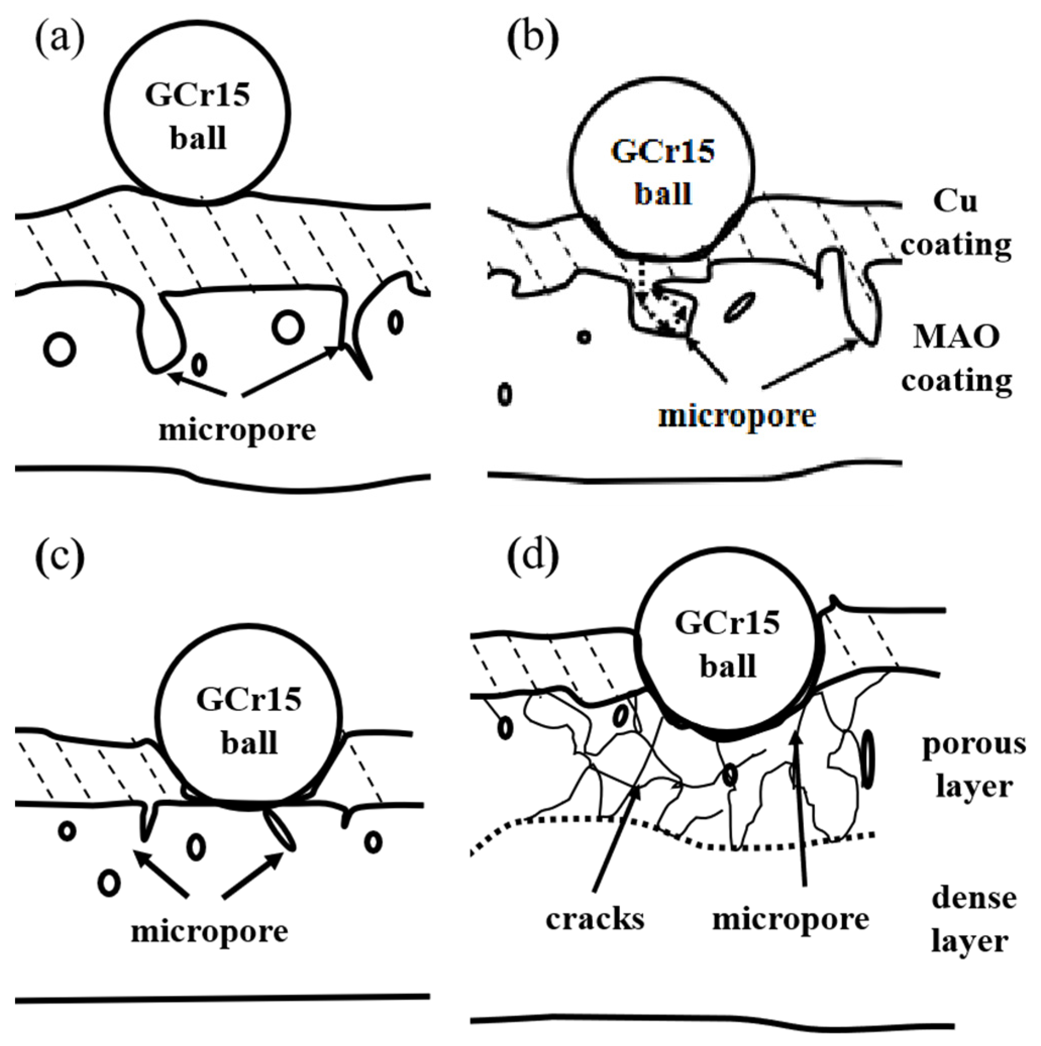
3.1. Characterization of Morphology

The working voltage determines the growth rate of the ceramic coating. The thickness of the MAO coating samples under different working voltages is measured by an eddy current thickness gauge are 2.18 ± 1.05 μm, 7.97 ± 1.15 μm, 12.48 ± 2.05 μm, and 31.71 ± 4.37 μm. The MAO coatings and MAO + Cu composite coatings developed after the single pretreatments were evaluated by SEM, EDS results are shown in Table 2. Figure 2a–d shows the SEM images of the MAO coating surface areas after different voltages. A large number of discharge channels remain on the surface of the ceramic coating, resulting in a large number of micropores with small diameters. When the voltage was increased, the number of micropores decreases, but the pore diameter increases. Micro arc oxidation reaction preferentially reacts at the defects with low internal resistance and oxygen release channels of the ceramic coating. In the process of continuous “melting → solidification → melting” of the ceramic coating, the ceramic coating is thickened continuously, and the deposition power consumption of a high resistance barrier layer required for MAO reaction on the surface of aluminum alloy samples continues to increase. However, a constant operating voltage does not increase the energy provided, causing the operating current to concentrate on the low resistance defect response and the micropores diameter to increase. Figure 2e–h shows the surface micro-morphology of the MAO + Cu composite coatings. The copper is typically “cauliflower-like” consisting of small spherical particles compactly formed with gaps between the particles. The copper in MAO-1 + Cu forms polymer protrusions (Figure 2e). Figure 2f shows the macropores of the ceramic coating. The filling effect of electroless copper plating is not obvious, and micro-pores can still be seen. Figure 2g,h shows that the copper layer on the surface of MAO-3 + Cu and MAO-4 + Cu composite coatings is relatively smooth, and the surface of the ceramic coating is full of micropores. From the cross-sectional SEM of the MAO + Cu coatings in Figure 2i–l, we can see clearly that, with the increase of the treatment voltage, the thickness of the surface copper coating is about 1–4 μm, and there are some defects such as micro-holes and micro-cracks in the cross-section of the ceramic coating. The electroless copper layer can fill these defects and integrate well with the ceramic coating.
However, a quite difference is still observed through the scanning results of copper plating. A three-dimensional profilometer is used to measure the coatings’surface roughness before and after electroless copper were shown in Table 3.
The surface roughness and surface area ratio decrease with the addition of top Cu coatings on the transition coatings. MAO coatings showed higher roughness than the composite coatings. After electroless copper plating, the top Cu coating is filled into the micropores and microcracks of the MAO coating. The average weight gains of the four types of MAO ceramics after copper plating were 200.87 mg, 257.56 mg, 177.34 mg, and 148.62 mg, respectively. The plating reaction rate was measured to determine the effect of the surface area on the copper plating reaction rate:
ν = ( Δ m × 10 4 ) ( ρ × S × t )
Here, Δm is the mass change (g) before and after copper plating; ρ is the density of the Cu coating (8.96 g/cm³); S is the size of the copper plating reaction area (cm2); and t is the reaction time (h).
The copper plating rate is 2.38 μm/h, 3.05 μm/h, 2.10 μm/h, and 1.76 μm/h, for preparing the MAO(1-4) + Cu composite coatings. Copper plating uses the same pretreatment and electroless copper plating, and the weight change comes from the change of MAO coating. Combined with Figure 2 SEM results, it was found that the copper coating penetrates into the internal pores of the ceramic coating and fills the pores. The rough and porous surface is more conducive to copper deposition. Thus, the MAO coating with high surface roughness and surface area ratio has a fast copper plating rate.

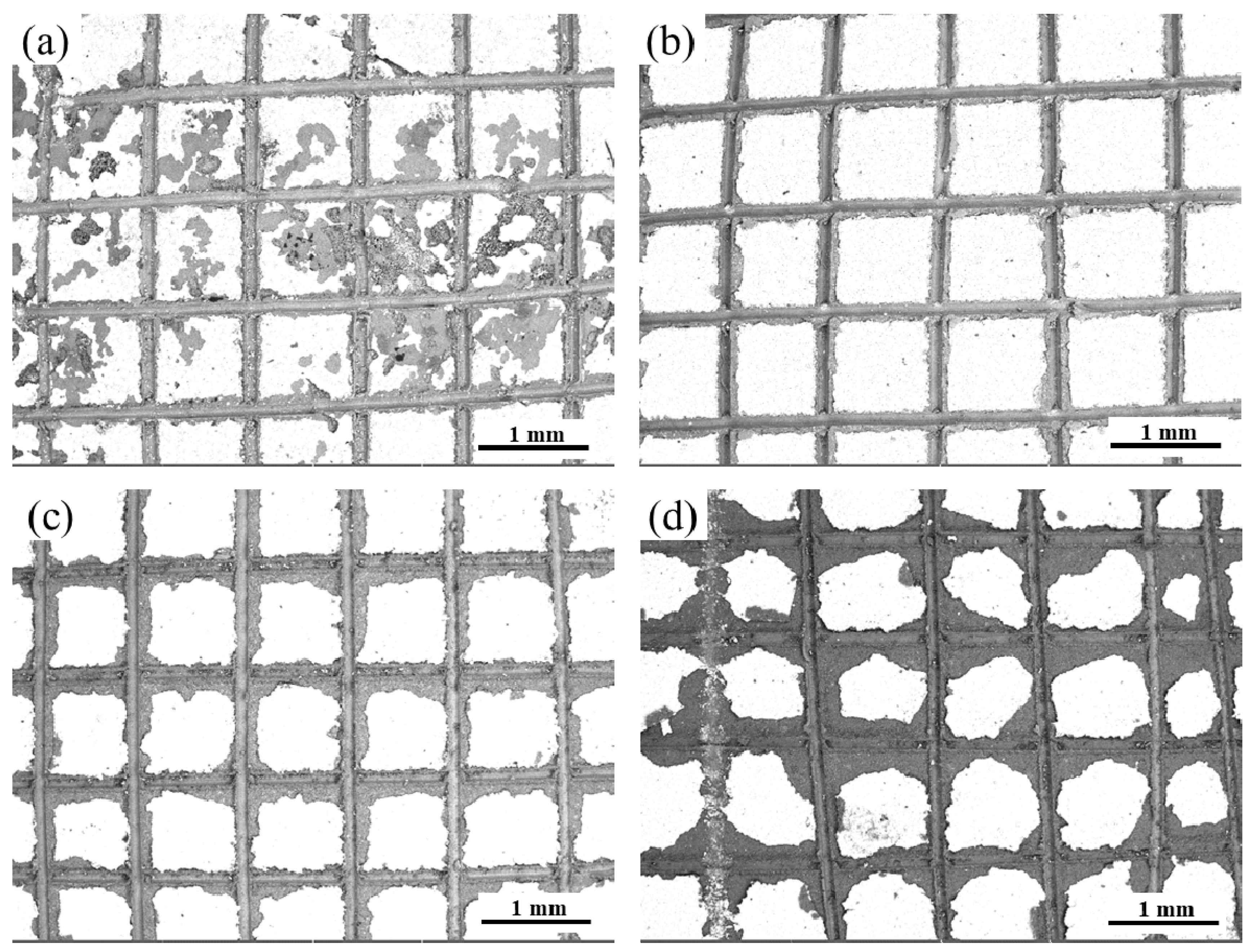
3.2. Analysis of Binding Strength

Figure 3 shows the pull-off of the composite coatings method results in the adhesion test. From Figure 3a that the removal area of MAO-1 + Cu is 15–35%, and the edge area and center area of the incision was greatly peeled off, reaching the 2B standard. The cutting edge of the MAO-2 + Cu composite coating in Figure 3b was completely smooth, and the composite coating has good adhesion strength, reaching the 4B standard. Only a small amount of peeling occurs at the edges and intersections of the MAO-3 + Cu composite coating, and the affected area is less than 15% (Figure 3c), which meets the 3B standard. The MAO-4 + Cu composite coating at the incision is more serious, reaching an interval of 15–35%, which is estimated to be a level 2B standard (Figure 3d). Copper penetrates into the internal pores of the ceramic coating, and the copper-plated layer and the MAO coating produce mechanical engagement, pinning or locking structures at the pores, and the combination is tight. Increasing the roughness of the ceramic coating and the size of the micropores provide a better bond for the adhesion of the copper coating on the surface of the ceramic coating.

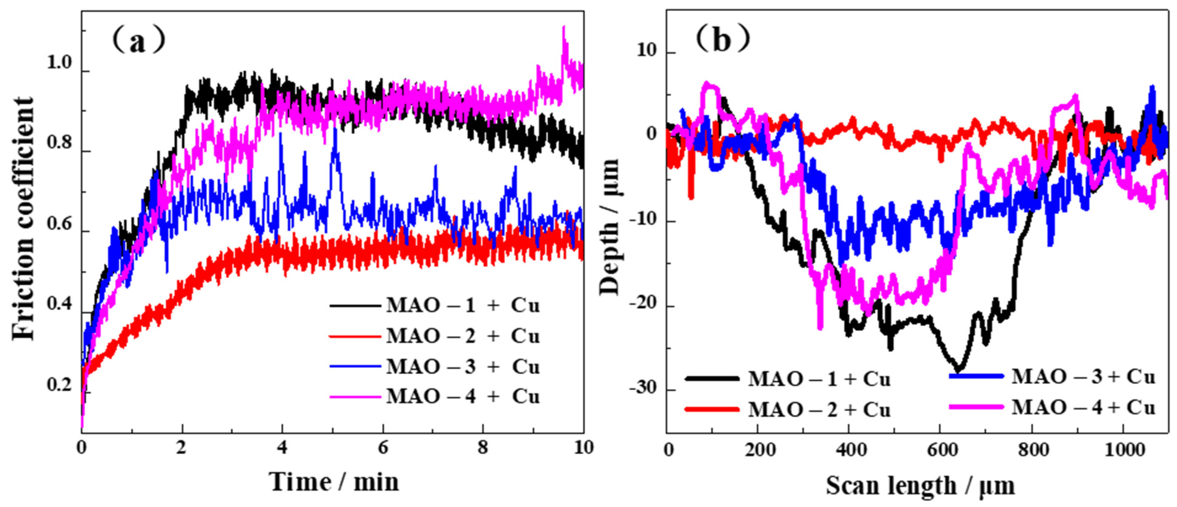
3.3. Characterization of Tribological Behavior

The change in friction coefficient with respect to time is shown in Figure 4a. The friction coefficient of the 6061 aluminum alloy matrix is about 0.7 [18]. The friction coefficient of Cu is about 0.6 [22]. The results of the friction coefficient test found that the MAO-2 + Cu composite coating with the highest copper plating rate and the best bonding force has the smallest average friction coefficient (0.5) and a small fluctuation range. Figure 4b shows the two-dimensional profile of the surface wear marks of different MAO + Cu composite coatings. The addition of the MAO + Cu composite coating can greatly reduce the wear depth and wear width of the aluminum alloy and the addition of the copper plating layer has a lubricating effect and further reduces the depth of the wear marks. After the wear test, SEM and EDS describe the surface morphology of the wear scar and the composition of the coating for revealing the wear mechanism of the composite coatings.
Figure 5 shows the SEM image and EDS result of the composite coatings after the wear test. The surface morphology of the wear marks and the elementary compositions of the surface after the wear test were measured by SEM and EDS. The Cu layer in the MAO-1 + Cu coating did not play a lubricating effect, with groove-like wear marks after the wear test, which may be the result of contact fatigue peeling (Figure 5a). However, the Cu layer on the surface of the MAO-2 + Cu coating in Figure 5b is intact. The EDS results in Table 4 show that the content of Cu and Al was 13.46% and 1.94%, respectively. The Fe element found in the wear traces come from the grinding ball. During the wear process, the Cu layer on the top will undergo plastic deformation and be squeezed into the remaining micropores of the MAO coating. The wear traces are shallow, and the Cu layer on the surface of the MAO-3 + Cu coating is worn away, but the MAO coating can still deliver good anti-wear protection (Figure 5c). The MAO-4 + Cu coating has extensive wear under the action of cyclic contact stress: The Cu layer is worn out and the MAO coating is severely worn (Figure 5d).
The MAO + Cu composite coatings wear progressed in three stages as schematically modeled in Figure 6. In the first stage in (Figure 6b), the copper layer is worn first, and the copper has good deformability, and part of the copper will be squeezed into the interior of the MAO ceramic surface of the microporous coating. In the next stage, which occurred after complete removal of the Cu layer, the high-hardness MAO ceramic coating can still play a certain protective role (Figure 6c). In the third stage, there is a period of time when the porous coating in the ceramic is relatively large and dominates after the outer oxide layer is completely removed. The compressive stress generated under the contact surface has caused the propagation of perpendicular and parallel cracks. The ceramic particles formed wear debris, and the wear amount was increased (Figure 6d).

4. Conclusions

In order to improve the appearance and durability of the aluminum alloy, a new ceramic matrix composite was prepared on an aluminum alloy substrate by micro arc oxidation and electroless copper plating. The surface of aluminum alloy was treated with MAO to form a ceramic coating mainly made of alumina. The higher operating voltage of constant pressure mode, the greater the thickness of the coating, the smaller the number of surface micropores, and the surface hardness first increases and then decreases. Electroless copper was filled into the pores of the MAO coating. The copper coating can continuously and evenly cover the surface of the ceramic coating and fill the micropores and microcracks to form a staggered bite, reduced porosity after coating of the copper. The MAO-2 + Cu composite coating is affected by the morphology of the MAO coating. The copper plating efficiency is the highest, the bonding force is also the best, and it has a low and stable friction coefficient. The Cu coating from the surface of the MAO-2 + Cu composite coating undergoes plastic deformation during wear and is squeezed into the residual micropores of the coatings. The shallower wear marks show good anti-wear and self-lubricating properties.

Supplementary Materials

The following are available online at https://www.mdpi.com/article/10.3390/coatings11101172/s1, Figure S1: three-dimensional surface morphology of MAO coating (a–d), and MAO + Cu composite coating (e–h).

Author Contributions

Conceptualization, methodology, and writing—original draft preparation, S.-K.W. and W.Y.; Writing—review and editing, W.G., Y.Z., and Y.-H.Y.; Supervision, J.C. All authors have read and agreed to the published version of the manuscript.

Funding

This work was financially supported by the Key Research and Development Plan of the Natural Science Foundation of China (52071252), the Key Research and Development Plan of Shaanxi Province industrial project (2021GY-208).

Institutional Review Board Statement

Not applicable.

Informed Consent Statement

Not applicable.

Data Availability Statement

Data is contained within the article.

Conflicts of Interest

The authors declare no conflict of interest.

References

  1. Mohamad, S.; Liza, S.; Yaakob, Y. Strengthening of the mechanical and tribological properties of composite oxide film formed on aluminum alloy with the addition of graphite. Surf. Coat. Technol. 2020, 403, 126435. [Google Scholar] [CrossRef]
  2. Famiyeh, L.; Huang, X.H. Plasma electrolytic oxidation coatings on aluminum alloys: Microstructures, properties, and applications. Mod. Concepts Mater. Sci. 2019, 2, 1–13. [Google Scholar]
  3. An, L.-Y.; Ma, Y.; Yan, X.-X.; Wang, S.; Wang, Z.-Y. Effects of electrical parameters and their interactions on plasma electrolytic oxidation coatings on aluminum substrates. Trans. Nonferrous Met. Soc. China 2020, 30, 883–895. [Google Scholar] [CrossRef]
  4. Szkodo, M.; Stanisławska, A.; Komarov, A.; Bolewski, L. Effect of MAO coatings on cavitation erosion and tribological properties of 5056 and 7075 aluminum alloys. Wear 2021, 474–475, 203709. [Google Scholar] [CrossRef]
  5. Pakiea, W.; Tanski, T.; Brytan, Z.; Chladek, G.; Pakiela, K. The impact of laser surface treatment on the microstructure, wear resistance and hardness of the AlMg5 aluminum alloy. Appl. Phys. A 2020, 126, 3. [Google Scholar] [CrossRef] [Green Version]
  6. Sobolev, A.; Peretz, T.; Borodianskiy, K. Fabrication and Characterization of Ceramic Coating on Al7075 Alloy by Plasma Electrolytic Oxidation in Molten Salt. Coatings 2020, 10, 993. [Google Scholar] [CrossRef]
  7. Kaewvilai, A.; Tanathakorn, R.; Laobuthee, A.; Rattanasakulthong, W.; Rodchanarowan, A. Electroless copper plating on nano-silver activated glass substrate: A single-step activation. Surf. Coat. Technol. 2017, 319, 260–266. [Google Scholar] [CrossRef]
  8. Wei, C.L.; Cheng, J.G.; Chen, P.Q.; Wei, B.; Gao, D.; Xu, D. Facile electroless copper plating on diamond particles without conventional sensitization and activation. Adv. Powder Technol. 2019, 30, 2751–2758. [Google Scholar] [CrossRef]
  9. Alirezaei, S.; Monirvaghefi, S.; Salehi, M.; Saatchi, A. Effect of alumina content on surface morphology and hardness of Ni-P-Al2O3(α) electroless composite coatings. Surf. Coat. Technol. 2004, 184, 170–175. [Google Scholar] [CrossRef]
  10. Pancrecious, J.K.; Deepa, J.P.; Jayan, V. Nanoceria induced grain refinement in electroless Ni-B-CeO2 composite coating for enhanced wear and corrosion resistance of Aluminium alloy. Surf. Coat. Tech. 2018, 356, 29–37. [Google Scholar] [CrossRef]
  11. Yin, Z.; Chen, F. Effect of nickel immersion pretreatment on the corrosion performance of electroless deposited Ni–P alloys on aluminum. Surf. Coat. Technol. 2013, 228, 34–40. [Google Scholar] [CrossRef]
  12. Abdel-Gawad, S.A.; Sadik, M.A.; Shoeib, M.A. Preparation and properties of a novel nano Ni-B-Sn by electroless deposition on 7075-T6 aluminum alloy for aerospace application. J. Alloy Compd. 2019, 785, 1284–1292. [Google Scholar] [CrossRef]
  13. Zhang, Z.; Yu, G.; Ouyang, Y.; He, X.; Hu, B.; Zhang, J.; Wu, Z. Studies on influence of zinc immersion and fluoride on nickel electroplating on magnesium alloy AZ91D. Appl. Surf. Sci. 2009, 255, 7773–7779. [Google Scholar] [CrossRef]
  14. Ma, C.; Cheng, D.; Zhu, X.; Yan, Z.; Fu, J.; Yu, J.; Liu, Z.; Yu, G.; Zheng, S. Investigation of a self-lubricating coating for diesel engine pistons, as produced by combined microarc oxidation and electrophoresis. Wear 2018, 394–395, 109–112. [Google Scholar] [CrossRef]
  15. Yang, W.; Xu, D.; Wang, J.; Yao, X.; Chen, J. Microstructure and corrosion resistance of micro arc oxidation plus electrostatic powder spraying composite coating on magnesium alloy. Corros. Sci. 2018, 136, 174–179. [Google Scholar] [CrossRef]
  16. Li, Z.-Y.; Cai, Z.-B.; Cui, Y.; Liu, J.-H.; Zhu, M.-H. Effect of oxidation time on the impact wear of micro-arc oxidation coating on aluminum alloy. Wear 2019, 426–427, 285–295. [Google Scholar] [CrossRef]
  17. Yang, W.; Xu, D.P.; Wang, J.L.; Jiang, B.L. Preparation of MAO coatings doped with graphene oxide. Surf. Eng. 2016, 33, 739–743. [Google Scholar] [CrossRef]
  18. Yang, W.; Wu, S.; Xu, D.; Gao, W.; Yao, Y.; Guo, Q.; Chen, J. Preparation and performance of alumina ceramic coating doped with aluminum nitride by micro arc oxidation. Ceram. Int. 2020, 46, 17112–17116. [Google Scholar] [CrossRef]
  19. Mo, Q.; Qin, G.; Ling, K.; Lv, X.; Wang, N.; Li, W. Layer-by-layer self-assembled polyurea layers onto MAO surface for enhancing corrosion protection to aluminum alloy 6063. Surf. Coat. Tech. 2021, 405, 126653. [Google Scholar] [CrossRef]
  20. ASTM D 3359-17 Standard Test Methods for Measuring Adhesion by Tape Test; American Society of Testing Materials: West Conshohocken, PA, USA, 2017.
  21. GB/T 5270-2005 Metallic Coatings on Metallic Substrates-Electrodeposited and Chemically Deposited Coatings-Review of Methods Available for Testing Adhesion; General Administration of Quality Supervision, Inspection and Quarantine of the People’s Republic of China: Beijing, China, 2005.
  22. Winzer, J.; Weiler, L.; Pouquet, J.; Rödel, J. Wear behaviour of interpenetrating alumina–COPPER composites. Wear 2011, 271, 2845–2851. [Google Scholar] [CrossRef]
Figure 1. (a) Preparation flow chart of composite coating, variation trend of (b) voltage and (c) current in micro arc oxidation.
Coatings 11 01172 g001
Figure 2. Surface morphology of MAO coating (ad), surface morphology of MAO + Cu composite coating (eh) and cross-section morphology of MAO + Cu composite coating (il). three-dimensional pictures are provided as Supplementary Figure S1.
Coatings 11 01172 g002
Figure 3. Binding strength of composite coatings: (a) MAO-1+ Cu; (b) MAO-2 + Cu; (c) MAO-3 + Cu; (d) MAO-4 + Cu.
Coatings 11 01172 g003
Figure 4. (a) Coefficient of friction of four composite coatings as a function of sliding time and (b) corresponding surface profiles of the wear tracks after friction test.
Coatings 11 01172 g004
Figure 5. Surface morphologies and EDS results of composite coatings after friction tests: (a) MAO-1 + Cu; (b) MAO-2 + Cu; (c) MAO-3 + Cu; (d) MAO-4 + Cu.
Coatings 11 01172 g005
Figure 6. Schematic diagram of friction test of MAO + Cu composite coatings: (a) before; (b) first stage; (c) second stage; (d) third stage.
Coatings 11 01172 g006
Table 1. Condition parameters for MAO, pretreatment, and electroless copper plating onto the aluminum surface.
ProcessChemical SubstancesExperimental Conditions
MAO12 g/L Na2SiO3,
1.2 g/L NaOH
Frequency (500 Hz), Duty cycle (10%),
Output voltages (400, 450, 500, 550 V),
Temperature < 40 °C, Reaction time 20 min.
Sensitization30 g/L SnCl2,
30 mL/L HCl
Ultrasonic vibration, Room temperature, 4 min
Activation6g/L AgNO3,
A small amount of NH4OH
Ultrasonic vibration, Room temperature, 4 min
Chemical
Copper
plating
14 g/L CuSO4 × 5H2O,
60 g/L C4H4KNaO6,
0.1 g/L K4Fe (CN)6 × 3H2O,
15 mL/L HCHO,
50 mL/L CH3OH,
A certain amount of NaOH
pH: 12.5 ± 0.1, Magnetic stirring speed 100 r/min,
Constant temperature 30 ℃, Reaction time 30 min.
Table 2. EDS analysis of the MAO coatings surface before and after the electroless copper plating (at.%).
ElementsCoatings
MAO-1MAO-2MAO-3MAO-4MAO-1 + CuMAO-2 + CuMAO-3 + CuMAO-4 + Cu
O49.9859.9661.0762.65----
Al47.5231.2126.2523.743.390.140.600.30
Si1.667.4911.1611.78----
Mg0.630.510.420.39----
Na0.200.830.701.45----
Cu----96.6199.8699.4099.70
Table 3. Surface hardness, roughness, and surface area ratio of MAO coating before and after electroless copper plating.
CoatingsBefore Cu PlatingAfter Cu Plating
Hardness
/HV0.2
Roughness/μmActual Area/Smooth SurfaceHardness
/HV0.2
Roughness/μmActual Area/Smooth Surface
MAO-1204.70.551.27128.40.671.23
MAO-2296.12.853.53126.81.181.31
MAO-3407.82.412.27129.51.131.25
MAO-496.21.951.60132.71.631.28
Table 4. EDS analysis of MAO + Cu composite coatings after abrasion test (at.%).
ElementsMAO-1 + CuMAO-2 + CuMAO-3 + CuMAO-4 + Cu
O7.5216.5944.3444.37
Al91.802.956.1939.61
Cr00.070.290.09
Fe0.085.3616.296.35
Cu0.5975.0332.899.59
Publisher’s Note: MDPI stays neutral with regard to jurisdictional claims in published maps and institutional affiliations.

