
Terahertz Reconfigurable Planar Graphene Hybrid Yagi–Uda Antenna

 and
and
Abstract
1. Introduction
2. Antenna Design
2.1. Graphene Modeling
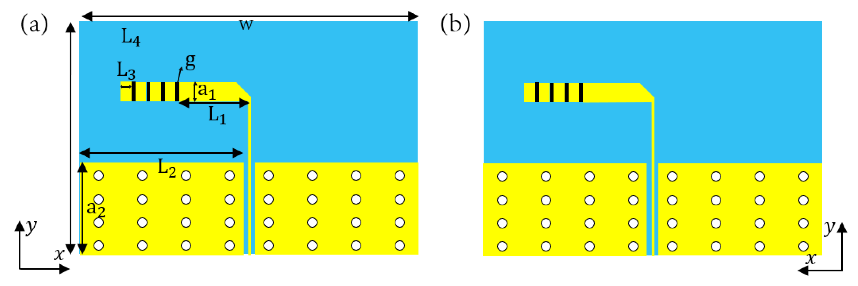
2.2. Frequency Reconfigurable Dipole Antenna Design
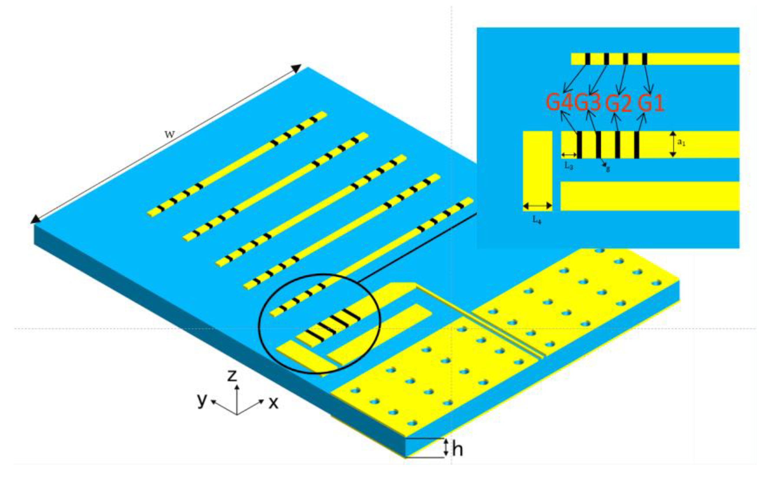
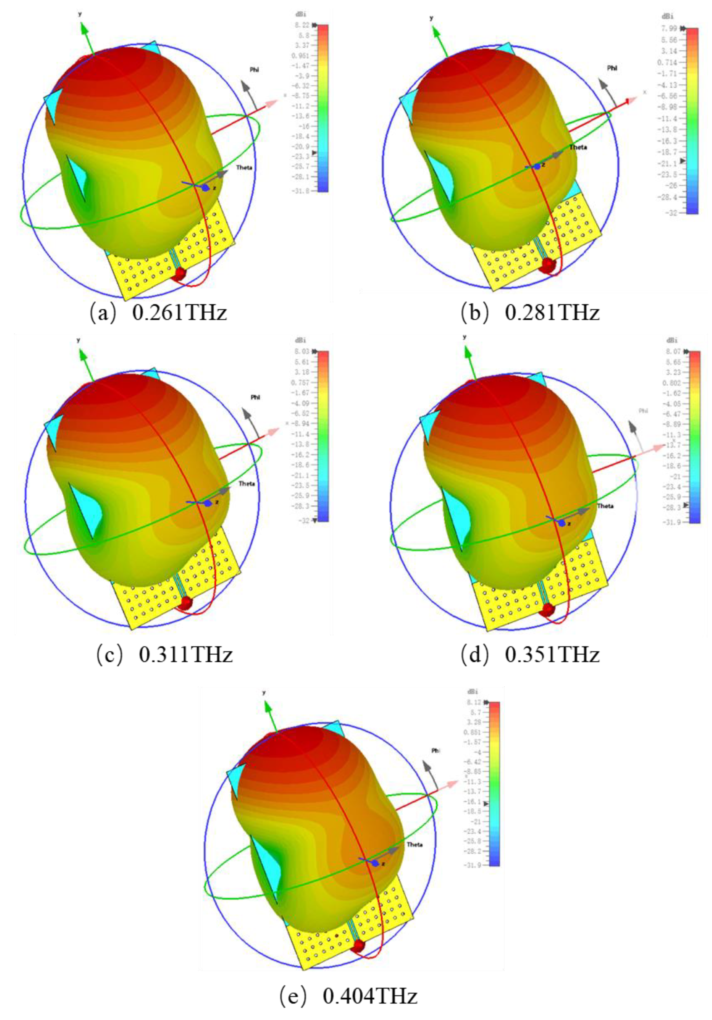
2.3. Frequency Reconfigurable End-Fire Antenna Design
3. Conclusions
Author Contributions
Funding
Data Availability Statement
Conflicts of Interest
References
- Kleine-Ostmann, T.; Nagatsuma, T. A review on terahertz communications research. J. Infrared Millim. Terahertz Waves 2011, 32, 143–171. [Google Scholar]
- Marcus, M.J. ITU WRC-19 spectrum policy results. IEEE Wirel. Commun. 2019, 26, 4–5. [Google Scholar]
- Dash, S.; Patnaik, A. Material selection for THz antennas. Microw. Opt. Technol. Lett. 2018, 60, 1183–1187. [Google Scholar] [CrossRef]
- Kleiner, R.J.S. Filling the terahertz gap. Science 2007, 318, 1254–1255. [Google Scholar] [PubMed]
- Maurya, N.K.; Ghosh, J. Design of graphene-based tunable ultra-thin UWB metasurface for terahertz regime. Optik 2023, 279, 170753. [Google Scholar]
- Maurya, N.K.; Kumari, S.; Pareek, P.; Singh, L. Graphene-based frequency agile isolation enhancement mechanism for MIMO antenna in terahertz regime. Nano Commun. Netw. 2023, 35, 100436. [Google Scholar]
- Nickpay, M.-R.; Danaie, M.; Shahzadi, A. Wideband rectangular double-ring nanoribbon graphene-based antenna for terahertz communications. IETE J. Res. 2022, 68, 1625–1634. [Google Scholar]
- Fakharian, M.M. A graphene-based multi-functional terahertz antenna. Optik 2022, 251, 168431. [Google Scholar]
- Moradi, K.; Pourziad, A.; Nikmehr, S. A frequency reconfigurable microstrip antenna based on graphene in Terahertz Regime. Optik 2021, 228, 166201. [Google Scholar]
- Zarrabi, F.B.; Seyedsharbaty, M.M.; Ahmed, Z.; Arezoomand, A.S.; Heydari, S. Wide band yagi antenna for terahertz application with graphene control. Optik 2017, 140, 866–872. [Google Scholar] [CrossRef]
- Chashmi, M.J.; Rezaei, P.; Kiani, N. Reconfigurable graphene-based V-shaped dipole antenna: From quasi-isotropic to directional radiation pattern. Optik 2019, 184, 421–427. [Google Scholar] [CrossRef]
- Gotra, S.; Yadav, R.; Pandey, V.S. Beam reconfigurable graphene-based Yagi–Uda antenna with higher-order TM mode generation for THz applications. Opt. Eng. 2020, 59, 115103. [Google Scholar] [CrossRef]
- Wu, Y.; Qu, M.; Jiao, L.; Liu, Y. Tunable terahertz filter-integrated quasi-Yagi antenna based on graphene. Plasmonics 2017, 12, 811–817. [Google Scholar] [CrossRef]
- Maurya, N.K.; Kumari, S.; Pareek, P.; Varshney, G. Highly-efficient tunable dipole-driven Yagi–Uda antenna with end-fire radiation for terahertz application. Nano Commun. Netw. 2023, 38, 100480. [Google Scholar]


| Parameters | Values | Parameters | Values |
|---|---|---|---|
| a1 | 30 μm | L2 | 333.5 μm |
| a2 | 70 μm | L3 | 20 μm |
| W | 700 μm | L4 | 20 μm |
| L | 500 μm | g | 5 μm |
| L1 | 105 μm | a3 | 10 μm |
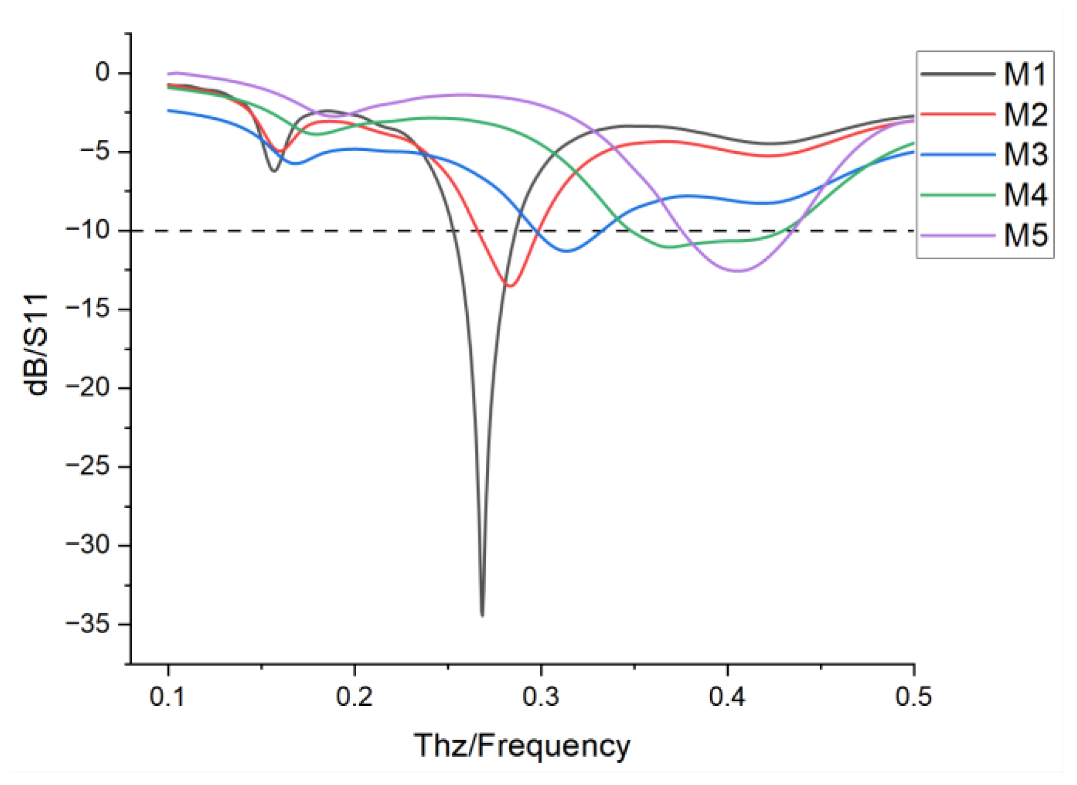
| Modes | g1 | g2 | g3 | g4 | Frequency |
|---|---|---|---|---|---|
| M1 | 5 ev | 5 ev | 5 ev | 5 ev | 0.268 THz |
| M2 | 0 ev | 5 ev | 5 ev | 5 ev | 0.283 THz |
| M3 | 0 ev | 0 ev | 5 ev | 5 ev | 0.311 THz |
| M4 | 0 ev | 0 ev | 0 ev | 5 ev | 0.395 THz |
| M5 | 0 ev | 0 ev | 0 ev | 0 ev | 0.416 THz |
| Modes | Group G1 | Group G2 | Group G3 | Group G4 | Frequency |
|---|---|---|---|---|---|
| M1 | 5 ev | 5 ev | 5 ev | 5 ev | 0.261 THz |
| M2 | 0 ev | 5 ev | 5 ev | 5 ev | 0.281 THz |
| M3 | 0 ev | 0 ev | 5 ev | 5 ev | 0.311 THz |
| M4 | 0 ev | 0 ev | 0 ev | 5 ev | 0.351 THz |
| M5 | 0 ev | 0 ev | 0 ev | 0 ev | 0.404 THz |
| Reference | Antenna Structure | Size (λ × λ) | F (THz) | Peak Gain(dBi) | Tuning Range (THz) |
|---|---|---|---|---|---|
| [11] | Graphene | NR | 0.95 | 1.13 | 0.7–0.98 |
| [12] | Graphene | 2.5 × 2.5 | 7.83 | 4.43 | NR |
| [13] | PEC + Graphene | 0.58 × 0.63 | 1.9 | 5 | 1.86–2.35 |
| [14] | PEC + Graphene | 0.44 × 0.27 | 1.36 | 4.93 | 1.328–1.5 |
| This work | Copper + Graphene | 0.58 × 1 | 0.261, 0.281, 0.311, 0.351, 0.404 | 4.53 | 0.243–0.444 |
Disclaimer/Publisher’s Note: The statements, opinions and data contained in all publications are solely those of the individual author(s) and contributor(s) and not of MDPI and/or the editor(s). MDPI and/or the editor(s) disclaim responsibility for any injury to people or property resulting from any ideas, methods, instructions or products referred to in the content. |
© 2025 by the authors. Licensee MDPI, Basel, Switzerland. This article is an open access article distributed under the terms and conditions of the Creative Commons Attribution (CC BY) license (https://creativecommons.org/licenses/by/4.0/).
Share and Cite
Liu, Q.; Zhong, R.; Xu, B.; Dong, J.; Teng, G.; Zhong, K.; Wu, Z.; Zhang, K.; Hu, M.; Liu, D. Terahertz Reconfigurable Planar Graphene Hybrid Yagi–Uda Antenna. Nanomaterials 2025, 15, 488. https://doi.org/10.3390/nano15070488
Liu Q, Zhong R, Xu B, Dong J, Teng G, Zhong K, Wu Z, Zhang K, Hu M, Liu D. Terahertz Reconfigurable Planar Graphene Hybrid Yagi–Uda Antenna. Nanomaterials. 2025; 15(7):488. https://doi.org/10.3390/nano15070488
Chicago/Turabian StyleLiu, Qimeng, Renbin Zhong, Boli Xu, Jiale Dong, Gefu Teng, Ke Zhong, Zhenhua Wu, Kaichun Zhang, Min Hu, and Diwei Liu. 2025. "Terahertz Reconfigurable Planar Graphene Hybrid Yagi–Uda Antenna" Nanomaterials 15, no. 7: 488. https://doi.org/10.3390/nano15070488
APA StyleLiu, Q., Zhong, R., Xu, B., Dong, J., Teng, G., Zhong, K., Wu, Z., Zhang, K., Hu, M., & Liu, D. (2025). Terahertz Reconfigurable Planar Graphene Hybrid Yagi–Uda Antenna. Nanomaterials, 15(7), 488. https://doi.org/10.3390/nano15070488