Article

Synergistic LPCVD and PECVD Growth of β-Ga2O3 Thin Films for High-Sensitivity and Low-Dose Direct X-Ray Detection

1
School of Science, Inner Mongolia University of Technology, Hohhot 010051, China
2
College of Materials Science and Engineering, Inner Mongolia University of Technology, Hohhot 010051, China
3
School of Physical Science and Technology, Inner Mongolia University, Hohhot 010021, China
*
Authors to whom correspondence should be addressed.
Nanomaterials 2025, 15(17), 1360; https://doi.org/10.3390/nano15171360
Submission received: 19 August 2025 / Revised: 1 September 2025 / Accepted: 3 September 2025 / Published: 3 September 2025

Abstract

Ultra-wide bandgap β-Ga2O3 is a promising low-cost alternative to conventional direct X-ray detector materials that are limited by fabrication complexity, instability, or slow temporal response. Here, we comparatively investigate β-Ga2O3 thin films grown on c-sapphire by low-pressure chemical vapor deposition (LPCVD) and plasma-enhanced CVD (PECVD), establishing a quantitative linkage between growth kinetics, microstructure, defect landscape, and X-ray detection figures of merit. The LPCVD-grown film (thickness ≈ 0.289 μm) exhibits layered coalesced grains, a narrower rocking curve (FWHM = 1.840°), and deep-level oxygen-vacancy-assisted high photoconductive gain, yielding a high sensitivity of 1.02 × 10⁵ μC Gyair−1 cm−2 at 20 V and a thickness-normalized sensitivity of 3.539 × 10⁵ μCGyair−1 cm−2 μm−1. In contrast, the PECVD-grown film (≈1.57 μm) shows dense columnar growth, higher O/Ga stoichiometric proximity, and shallow-trap dominance, enabling a lower dark current, superior dose detection limit (30.13 vs. 57.07 nGyair s−1), faster recovery, and monotonic SNR improvement with bias. XPS and dual exponential transient analysis corroborate a deep-trap persistent photoconductivity mechanism in LPCVD versus moderated shallow trapping in PECVD. The resulting high-gain vs. low-noise complementary paradigm clarifies defect–gain trade spaces and provides a route to engineer β-Ga2O3 thin-film X-ray detectors that simultaneously target high sensitivity, low dose limit, and temporal stability through trap and electric field management.

1. Introduction

X-ray detection has demonstrated a wide range of potential applications in the domains of public safety, industrial non-destructive testing, medical imaging, and material microstructure investigation [1,2,3,4]. High-efficiency X-ray detectors must simultaneously feature high density, high resistivity, low crystal defect density, etc., to achieve efficient X-ray absorption, suppress dark current, enable the detection of low-dose-rate X-rays, and improve detector response speed, and high stability is also required to extend the service life [5,6,7]. Therefore, the development of high-performance X-ray detectors is crucial for achieving accurate and fast X-ray detection.
Currently, the most extensively used X-ray detectors in the commercial market are indirect conversion detectors [8], which convert X-rays into visible light through the introduction of scintillators and then convert visible light into electrical signals using photodiodes [9,10,11]. Compared to indirect detectors, direct-type X-ray detectors do not require scintillator materials for light conversion, offering a distinct advantage in terms of higher X-ray conversion efficiency, sensitivity, spatial resolution, and lower noise levels [12,13,14,15,16,17]. However, the commonly used direct X-ray detection materials, such as silicon (Si), amorphous selenium (a-Se), cadmium zinc telluride (CdZnTe), perovskite, etc., face issues like complex manufacturing processes, high costs, and poor stability, which limit their widespread application [18,19,20,21,22,23].
In recent years, the wide bandgap semiconductor gallium oxide (Ga2O3) has emerged as a new material choice for exploring high-performance X-ray detectors due to its high density, excellent thermal and chemical stability, significant radiation resistance, and inherent rigid structure [24,25,26,27,28]. Moreover, the X-ray absorption coefficient of Ga2O3 is far higher than that of diamond, comparable to that of Si and perovskite materials, and is less susceptible to visible light interference, which gives it significant advantages in the field of X-ray detection. Early work on unintentionally doped (UID) β-Ga2O3 single crystals established device feasibility for X-ray detection but suffered slow temporal response owing to abundant oxygen vacancies (VO) [29]. Fe doping increased resistivity and accelerated response through compensation of donor-like defects [30]. Mg doping of a single crystal β-Ga2O3 simultaneously raised resistivity, suppressed VO, and delivered 16 times the sensitivity of a-Se [31]. Al alloying widened the bandgap of single-crystal β-Ga2O3, lowering intrinsic carrier density and enabling high sensitivity [32]. Thus, intentional dopants (Fe, Mg, Al) systematically couple defect suppression with resistivity/band engineering to enhance performance. Although X-ray detectors based on Ga2O3 single crystals have made significant progress, there are still certain challenges in the integration of functional modules and large-scale applications due to difficulties in growing large-sized, high-quality single crystals and the lack of effective P-type doping.
Thin-film-based X-ray detectors have emerged at the forefront of current research owing to their advantages in large-area deposition on diverse substrates, direct monolithic integration with CMOS/flexible systems, compact device size, high integration density, and reduced manufacturing costs [33]. Significant advances have been made in recent years in the growth techniques, material processing, and corresponding device performance of Ga2O3 thin films. However, current thin-film fabrication techniques in Ga2O3 film-based X-ray detection are confronted by two major challenges: the limitations inherent in film formation processes restrict the preparation of large-area, high-quality films, and the concurrent optimization of sensitivity and detection limits alongside defect engineering and crystal quality remains unrealized, severely hindering their practical implementation. In 2024, Chen et al. [34] proposed enhancing the density of Ga2O3 films through indium (In) doping, fabricating an X-ray detector based on indium-doped gallium oxide (Ga2O3:In) microwires. However, the one-dimensional structure of the microwires makes the doping process highly susceptible to limitations such as doping non-uniformity, lattice defects, interface states, and carrier transport inefficiencies, compounded by challenges in scalable fabrication. Consequently, achieving high-sensitivity, low-detection-limit X-ray detectors with this approach remains difficult. In 2024, Liang et al. [35] first employed amorphous a-Ga2O3 films in X-ray neuromorphic synapses and found that the films exhibited an oxygen vacancies/lattice oxygen ratio of 1:0.39. The resultant high concentration of oxygen vacancies enhanced interfacial electron tunneling, yielding a sevenfold increase in X-ray sensitivity with irradiation cycles (from 20.5 to 164.1 μCmGyair−1 cm−2). However, the amorphous structure together with the elevated oxygen vacancy density led to extremely low carrier mobility, making it difficult to balance high sensitivity with a low detection limit. Wang et al. [36] fabricated 50 nm amorphous a-Ga2O3 films via atomic layer deposition (ALD), achieving an oxygen-vacancy-related ratio OII/(OI + OII) = 35.5%. The corresponding X-ray detector exhibited a sensitivity of 952 μCGyair−1 cm−2. Nevertheless, the inherently low ALD growth rate (0.55 Å per cycle) impedes rapid large-area fabrication; moreover, the minimal thickness inherently restricts X-ray absorption efficiency, particularly for high-energy photons. Kim et al. [37] grew 700 nm α-Ga2O3 films via hydride vapor phase epitaxy (HVPE). Metal–semiconductor–metal (MSM) detectors fabricated from these films exhibited a shift in the charge neutrality point, and their charge collection efficiency (CCE) decreased from 152.2% to 105.5% with rising X-ray dose rate. Also in 2024, Gan et al. [38] utilized MOCVD to synthesize β-Ga2O3 films and demonstrated that the growth mode transformed from island growth to step-flow by employing a 4° off-cut substrate together with a high growth temperature of 900 °C. The sensitivity reached as high as 3.72 × 10⁵ μCGyair−1 cm−2. This performance stems from photoconductive gain, where deep-level traps (e.g., self-trapped holes, oxygen vacancies) extend carrier lifetimes, enabling multiple electron transits before recombination. Although step-flow growth can reduce trap density, the persistence of deep-level traps still results in slow recovery dynamics, limiting applicability in fast temporal detection. Furthermore, the high cost of MOCVD and the combined requirement of MOCVD plus off-cut substrates impede compatibility with existing CMOS production lines.
Current Ga2O3 thin-film growth still lacks a route that unifies scale, defect moderation, and crystal quality, limiting device engineering application. To address these challenges, a complementary process paradigm integrating Low-Pressure Chemical Vapor Deposition (LPCVD) and Plasma-Enhanced Chemical Vapor Deposition (PECVD) was utilized to co-optimize β-Ga2O3 films in this work. We fabricated high-performance gallium oxide (Ga2O3) films and successfully constructed high-sensitivity X-ray detectors. We also investigated the underlying correlation mechanisms linking process parameters, film structure, defect properties, and device performance.

2. Materials and Methods

Figure 1a depicts the experimental setup used for β-Ga2O3 thin film deposition [39]. Metallic gallium (Ga) was loaded into a specially designed semi-closed evaporator as the evaporation source. Argon (Ar) gas was used as the carrier gas to transport the vaporized Ga to the c-Al2O3 substrate, and oxygen (O2) gas was used as a reactant gas. The system was evacuated before deposition. The heating temperature was set to 900 °C to evaporate the metallic gallium (Ga) into the gas phase. Simultaneously, Ar gas and O2 gas were introduced into the chamber with a flow rate of 200 sccm and 6 sccm, respectively. Two different processes were used in this study: low-pressure chemical vapor deposition (LPCVD) and plasma-enhanced chemical vapor deposition (PECVD). PECVD requires additional plasma generation by radio frequency inductively coupled plasma (ICP) excitation of the reaction chamber gas. The plasma will ionize the process gas and decompose it into atomic oxygen (O*) and peroxide/superoxide free radical intermediates. These activated substances react with the gaseous gallium, and form gallium oxide (Ga2O3) on the substrate surface. In both processes, the deposition time was 60 min, and the deposition pressure was set to 80 Pa. The plasma power was set to 50 W, and other parameters remained the same as in LPCVD. The above experiments have all been verified to be repeatable.
Ti/Au (100 nm/100 nm) electrodes were deposited on the thin film surface using magnetron sputtering equipment (JGP 450G, SKY Technology Development Co., Ltd., Shengyang, China). The metal electrodes feature a finger width of 200 μm and a finger length of 3800 μm. The count of electrodes is 5 pairs (as shown in Figure 1b), and their effective illumination area is 0.0912 cm2. The physical photograph of the fabricated device is shown in Figure 1c. The surface and cross-section morphology of the films were observed using a scanning electron microscope(SEM) (SU 8820, Hitachi, Tokyo, Japan), and the thickness was measured from the cross-section morphology; the optical transmittance of the films was tested and the optical bandgap was calculated by a UV–vis spectrophotometer (JASCO V-760, JASCO Corporation, Tokyo, Japan); the crystalline quality and stress distribution of the films was measured by an X-ray diffractometer (XRD) (Empyrean, Malvern Panalytical, Malvern, UK); steady-state fluorescence spectrometer (Edinburgh FLS1000, Livingston, UK) was used to measure the Photoluminescence excitation spectra of the Ga2O3 thin film; and X-ray photoelectron spectroscopy (XPS) (ESCALAB 250Xi, Thermo Fisher, Waltham, MA, USA) to quantitatively analyze the elemental composition and content of the films. In X-ray detector performance testing, the X-ray source used is XH501, produced by Dandong Zhida Radiativey Co., Ltd. (Dandong, China), with a silver target, tube voltage of 40 kV, and tube current adjustment range of 0~550 μA. Since the X-ray dose rate is proportional to the tube current, it can achieve a dose rate output of 0~2312 μGyair/s. The X-ray dose rates corresponding to different X-ray tube currents are shown in Table 1. In all tests, X-rays were irradiated perpendicular to the β-Ga2O3 detector at an irradiation distance of 2.5 cm.

3. Results and Discussion

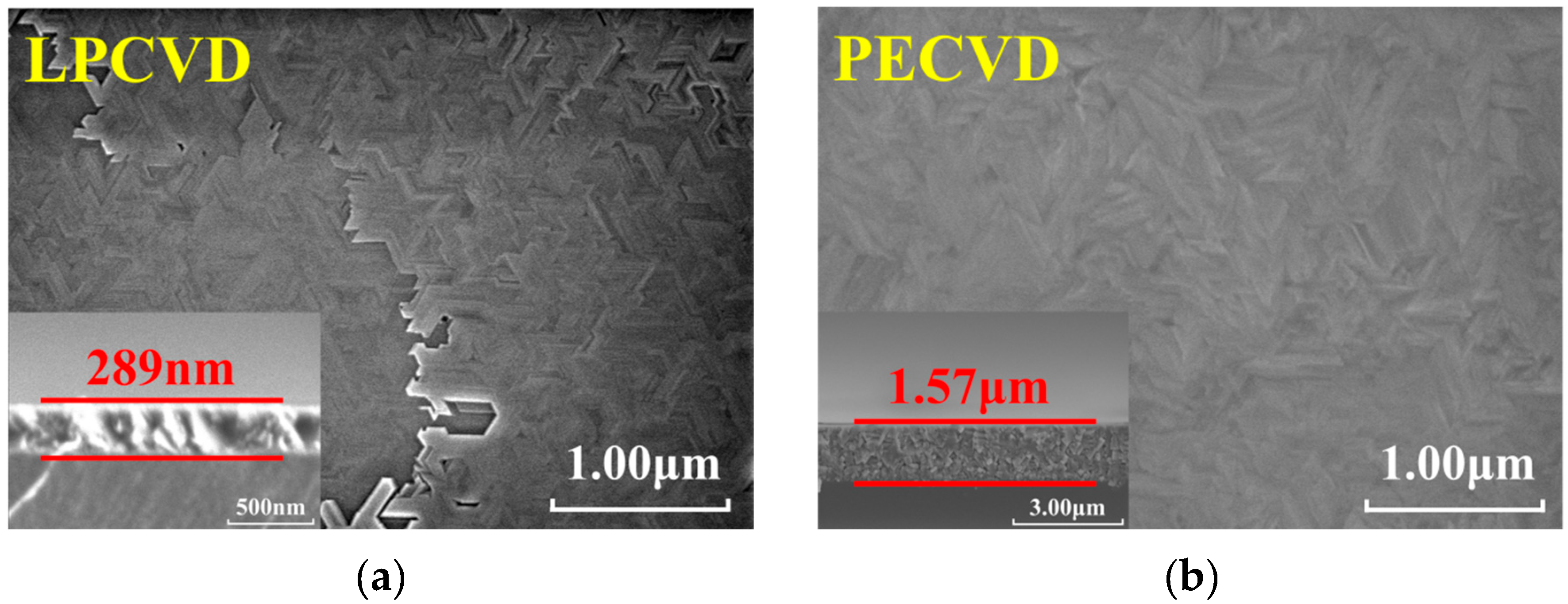
Figure 2a,b show scanning electron microscope (SEM) images of Ga2O3 thin films’ surface grown by using LPCVD and PECVD processes, respectively, and the insets show the cross-sectional morphology of the two films. It can be observed that the thin film grown by LPCVD exhibits a regular crystal structure with clear grain boundaries and surface morphology showing significant stacking phenomena, presenting a layered growth mode. The film thickness is 289 nm, with a relatively slow growth rate. Cross-sectional morphology indicates that at lower growth rates, grains merge sufficiently laterally. The thin film grown by PECVD shows no obvious pores or defects on the surface, exhibits grain boundary ridges with slight undulations, significantly improved surface density, and a quasi-columnar to columnar cross-section that continuously extended with island-like growth. The PECVD film achieved a thickness of approximately 1.57 μm within the same deposition time, with the growth rate significantly enhanced, reflecting a plasma-activated vertical growth kinetics mechanism. This indicates that plasma can introduce more active particles on the surface and promote more surface reactions, which helps optimize lattice matching and interface bonding between epitaxial films and substrates, making it easier for atoms to adsorb and nucleate on the substrate and form uniform, dense films. It also reflects the characteristics of incomplete lateral rearrangement after rapid multi-point nucleation. This difference in growth kinetics between “dense-coalescence dominated” and “rapid-columnar extension” demonstrates that different preparation processes can significantly alter the properties of β-Ga2O3 films.
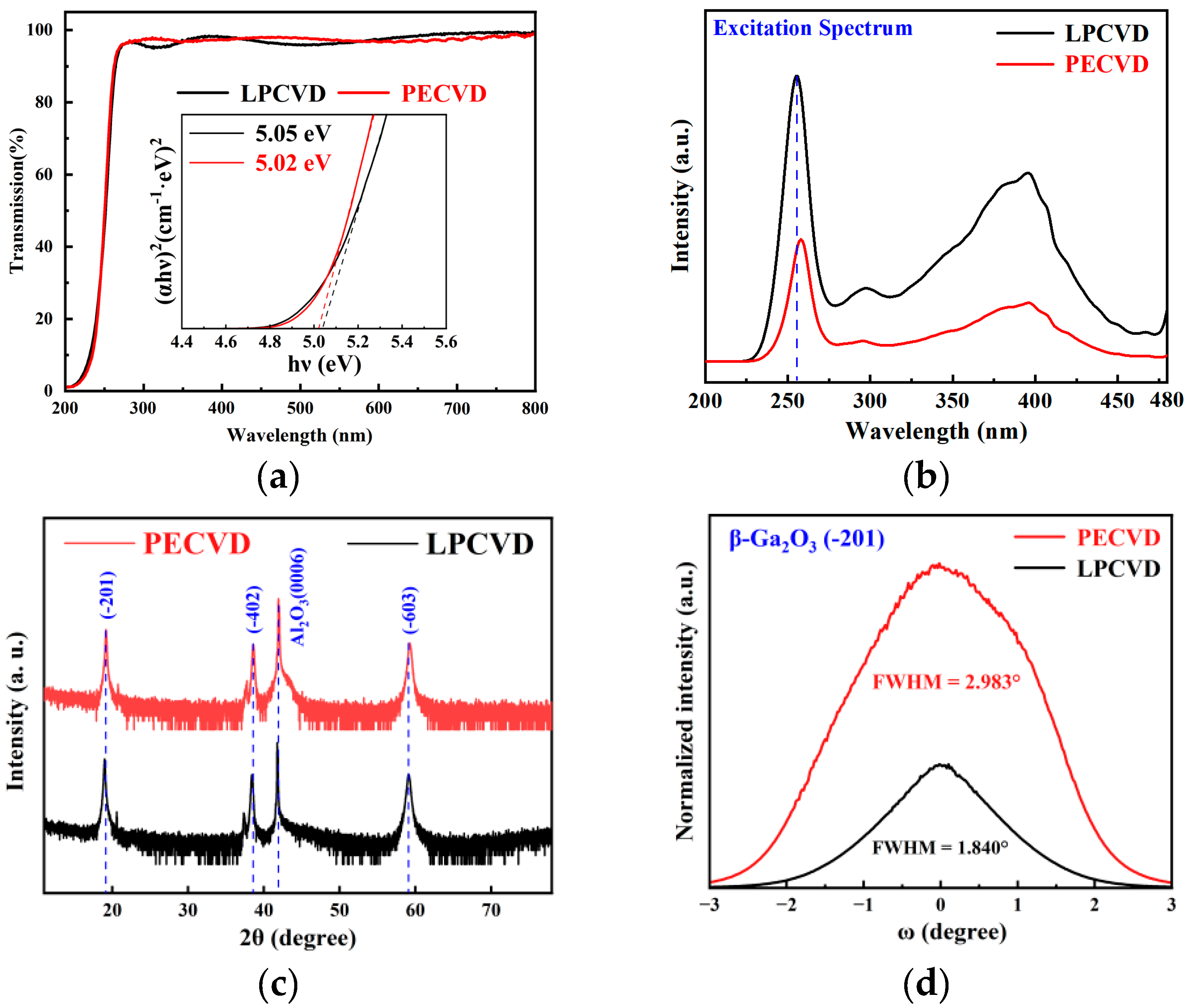
Figure 3a depicts the transmittance of the gallium oxide films grown by using the two processes. The incident light transmittance of both samples exceeds 90% in the visible wavelength range. To further analyze the optical bandgap properties of the thin films more extensively, the Tauc equation was used as follows [40]:
α h ν A 2   =   h ν     E g ,
α   =   1 / d ln 1 / T ,
where α is the absorption coefficient; h is Planck’s constant; ν is the frequency of the incident photon; d is the thickness of the film; and T is transmittance. Combined with the transmission spectra of the film, the horizontal coordinate is and the vertical coordinate is (αhν)2; a straight line can be obtained by linearly fitting the absorption mutation data. Through extrapolation of the linear region, the optical bandgap Eg of the film can be calculated, as shown in the inset. The band gap of the LPCVD-grown film is 5.05 eV; the band gap of the PECVD-grown film is 5.02 eV. Eg of PECVD-grown film is slightly higher, possibly due to fitting error or indicating weaker Urbach tail states/shallow defect absorption and fewer surface/bulk defect recombination centers.
Figure 3b presents the photoluminescence excitation (PLE) spectra of the films grown via LPCVD and PECVD. Distinct excitation peaks appear at 255 nm and 258 nm for the LPCVD and PECVD samples. Using Formula (3), the bandgap energies were calculated to be 4.87 eV and 4.81 eV [41], respectively. These values, corroborated by the bandgap values extracted using the Tauc equation, confirm that the LPCVD-grown film possesses a marginally larger bandgap than its PECVD counterpart.
E g   =   h c λ
Here, h represents the Planck constant; c is the speed of light in a vacuum; and λ is the peak wavelength of the excitation spectrum.
Figure 3c shows the XRD characterization of the films. The Bragg diffraction peaks corresponding to (−201), (−402), and (−603) crystals originating from β-Ga2O3 can be observed, indicating that the films are all growing preferentially in the direction of (−201). However, there are no obvious diffraction signals except for the diffraction peaks of the above crystal planes, which shows that the grown gallium oxide thin films are pure phase β-Ga2O3. In order to further analyze the crystallinity of β-Ga2O3 thin films, the (−201) crystal plane diffraction peak in XRD was analyzed. It was found that the full width at half maximum (FWHM) of the Ga2O3 thin film grown by LPCVD was 0.147°, and the FWHM of the Ga2O3 thin film grown by PECVD was 0.173°. This indicates that the thin films have good crystallinity, and the β-Ga2O3 thin film grown by PECVD has smaller grain size and a more refined structure.
In order to characterize the orientation dispersion and crystal quality of the β-Ga2O3 thin film, high-resolution XRD rocking curve measurements were performed on the (−201) crystal plane of the films, as shown in Figure 3d. The FWHM of the rocking curve for the film grown by LPCVD was measured to be 1.840°, while the FWHM of the rocking curve for the films grown by PECVD was 2.983°. Thus, it can be seen that β-Ga2O3 thin films exhibit high crystallinity and orientation. Meanwhile, the FWHM of the rocking curve of β-Ga2O3 thin film grown by PECVD is wider than that of LPCVD, indicating larger grain tilt and mosaic spread in PECVD-grown films. Combined with SEM data, the larger FWHM is attributed to the high initial nucleation density induced by highly active oxygen in PECVD, insufficient lateral coalescence, and rapid vertical advancement along with columnar interface stress freezing, which jointly restrict tilt reduction.
We employed the Scherrer equation to calculate the crystallite sizes of the thin films grown via LPCVD and PECVD based on the full width at half maximum (FWHM) of the rocking curves, yielding values of 4.51 nm and 2.77 nm, respectively. The crystallite size is inversely proportional to the FWHM of the rocking curve: a smaller crystallite size corresponds to a larger FWHM, while a larger crystallite size results in a narrower FWHM. This relationship is consistent with the FWHM values derived from the rocking curve analysis.
The chemical states of elements in films grown by two processes were investigated by X-ray photoelectron spectroscopy (XPS). All spectra were calibrated against the reference C 1s peak at 284.8 eV, and the binding energy uncertainty is approximately ±0.05 eV. For quantitative analysis of oxygen vacancy (VO) defect concentration, XPS tests were conducted on the O 1s energy level followed by Gaussian fitting peak analysis, as shown in Figure 4a,b. The O 1s spectra can be divided into three characteristic peaks: OI corresponds to lattice oxygen of the O-Ga bond in Ga2O3, OII represents oxygen vacancy defects in the oxide, and O mainly originates from surface chemical adsorbed substances (such as adsorbed O2, OH, etc.). In the film grown by LPCVD, three peaks are located at 530.07 eV, 531.43 eV, and 532.33 eV, respectively; in the film grown by PECVD, three peaks are located at 530 eV, 531.41 eV, and 532.99 eV. Since OII/(OI + OII) reflects the concentration of oxygen vacancies, the calculation results show that the oxygen vacancy concentrations in the films grown by LPCVD and PECVD are 13.64% and 17.38%, respectively. Although the OI/(OI + OII) ratio of PECVD samples is higher than that of LPCVD, it is important to note that PECVD can introduce plasma-activated oxygen (O*, peroxy/superoxide intermediates) and surface hydroxy groups, which are prone to produce overlapping in the OII energy level region. This component includes transient activated adsorption and reoxidation transition state and is not entirely equivalent to an increase in stable lattice oxygen vacancies as deep defects. Furthermore, during subsequent mild annealing, they can be further incorporated into the lattice, thereby reducing the density of steady-state oxygen vacancies.
According to the XPS spectra of Ga 3d, shown in Figure 4c, the binding energy corresponding to Ga 3d in the LPCVD-grown film is 19.52 eV, and the binding energy of Ga 3d in the film grown by PECVD is 19.42 eV. The Ga 3d main peak is located in the 19.4–19.5 eV range under both processes, corresponding to the Ga3+-O bond. Compared with LPCVD, the peak position of PECVD samples slightly shifts towards lower binding energy by approximately 0.10 eV (this magnitude exceeds the uncertainty limit of ±0.05 eV for energy calibration and differential charging). This can be attributed to the subtle redistribution of local chemical/stress environments and differences in electron screening brought about by rapid plasma oxidation or possibly due to more complete oxidation, reducing suboxide clusters leading to local potential field homogenization, suggesting that PECVD films possess more uniform local potentials and lower defect concentrations.
To gain a deeper understanding of the impact of oxygen vacancies on the overall chemical state of materials, Formula (4) was used to calculate the atomic ratio of O to Ga. The peak areas of Ga 3d and O 1s (IO 1s, IGa 3d) were extracted from the XPS data, then normalized by dividing by the elemental sensitivity factors (SO 1s = 0.711, SGa 3d = 0.34), and, finally, the ratio of the normalized areas is the atomic ratio of O to Ga [42,43].
O / G a   =   I O 1 s / S O 1 s I G a   3 d / S G a   3 d ,
According to calculations, the O/Ga atomic ratio (PECVD: 1.343; LPCVD: 1.298) was obtained. The PECVD sample is closer to the ideal stoichiometry of Ga2O3 (O/Ga = 1.5), indicating that the PECVD sample is more fully oxidized and has more complete chemical coordination. The reduction in a small amount of oxygen vacancies not only reduces the mid-gap defect states, which is beneficial for suppressing carrier scattering and non-radiative recombination, but also reduces the local stress and structural disorder induced by point defects, thereby improving the crystal quality.
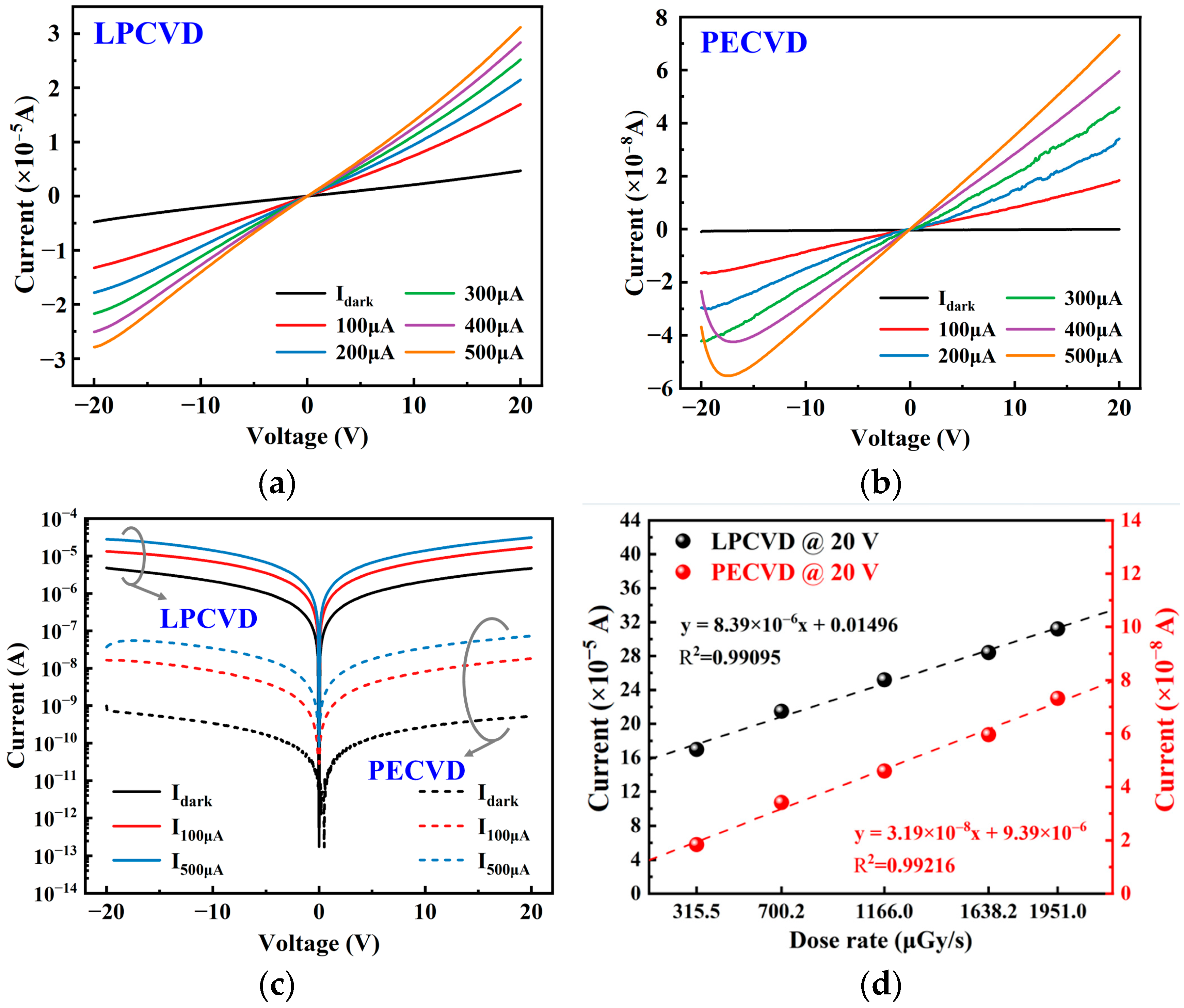
Two samples were fabricated into MSM structure X-ray detectors (Figure 1b,c). As shown in Figure 5a,b, both β-Ga2O3 MSM devices (LPCVD and PECVD) exhibited near-linear I–V characteristics under X-ray irradiation with tube voltage of 40 kV and tube current of 100–500 μA, as well as in dark state, indicating good ohmic contact at the metal/semiconductor interface. The current of both types of devices increases almost linearly with bias voltage under X-ray irradiation, indicating low interface barriers and minimal carrier injection limitations. Based on inter-band recombination theory, the recombination probability of carriers generated under X-ray irradiation increases with the carrier density and is proportional to the incident X-ray dose rate [44]. When the tube current is 400 μA and 500 μA, the photocurrent of the X-ray detector fabricated by PECVD exhibits a slight inflection characterized by “initial slight decline followed by rebound” as the bias voltage increases. This phenomenon can be attributed to the temporary limitation of effective mobility or lifetime caused by competitive filling of traps (partially deep/intermediate energy levels) in the moderate bias region. At higher electric fields, the drift time shortens rapidly, traps tend to saturate, and photoconductive gain is restored and enhanced.
The logarithmic I–V characteristics of the β-Ga2O3-based X-ray detector in dark state and under X-ray irradiation at room temperature are shown in Figure 5c. Under X-ray irradiation, the detector current significantly increases, which is related to the generation of photoelectron-hole pairs and secondary electrons [45]. In comparison, the X-ray detector fabricated by PECVD exhibits lower dark current, indicating that shallow energy level traps dominate and reduce leakage caused by thermal excitation or slow recombination; its photocurrent increases more smoothly with dose rate (tube current), demonstrating electrical stability and uniformity of defect distribution.
Figure 5d shows the relationship between dose rate and X-ray response current for β-Ga2O3 MSM detectors fabricated by LPCVD and PECVD under a bias voltage of 20 V. The photocurrent of the device fabricated by LPCVD is on the order of 10−5 A, approximately 103 times higher than that of PECVD (10−8 A), and both exhibit an approximately linear relationship within this dose rate range, IX-raykD1, indicating a balance between carrier recombination and generation. The higher slope suggests that the detector fabricated by LPCVD has a stronger trap-assisted photoconductive gain, while the detector fabricated by PECVD demonstrates lower gain but shows potential for faster and more stable response.
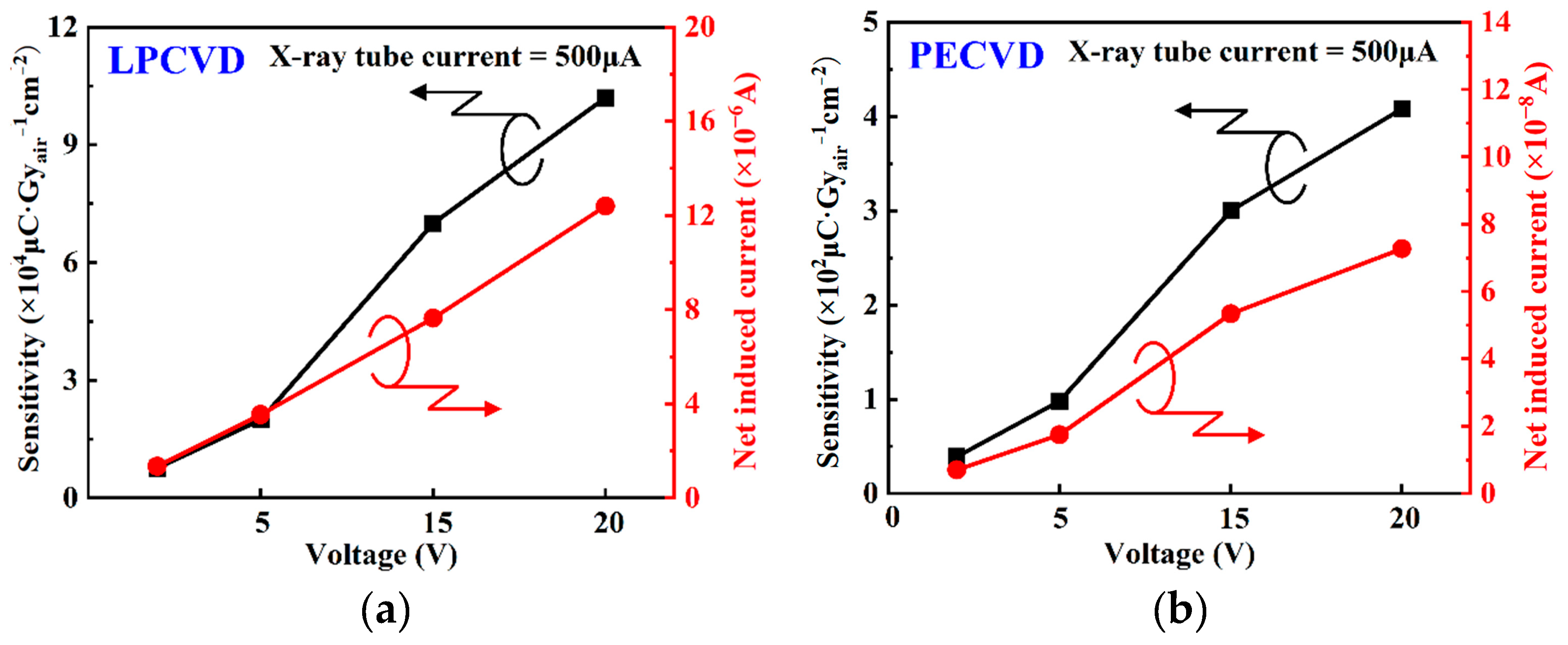
Figure 6a,b present the variations in net induced current and sensitivity under different biases (2, 5, 15, 20 V) at a fixed X-ray tube current of 500 μA. Sensitivity is defined as follows [8]:
S   =   I X - r a y     I d a r k D A ,
where IX-ray is the photocurrent generated by X-ray irradiation; Idark is the dark current; D is the X-ray dosage rate; and A is the effective detection area. As demonstrated in Figure 6a,b, the net induced current (IX-rayIdark) and sensitivity rise monotonically as the bias voltage increases, reflecting the synergistic improvement of carrier collection efficiency and photoconductive gain by electric field enhancement (derived from the high electric field reducing τT and improving the carrier collection efficiency) [31]. At a bias voltage of 20 V, the LPCVD-fabricated detector achieved a sensitivity of 1.02 × 10⁵ μCGyair−1 cm−2, significantly higher than the 408 μCGyair−1 cm−2 of the detector fabricated by PECVD. This difference may be related to potential deep traps extending carrier lifetime and thus amplifying photoconductive gain, may also include composite effects from differences in thickness and absorption path.
To eliminate geometric and thickness (d) factors, normalized sensitivity (Snorm) is defined as follows:
S n o r m   =   S / d
After separating the thickness factor, it is similarly observed that the normalized sensitivity of the LPCVD-fabricated detector reached 3.539 × 10⁵ μCGyair−1 cm−2 μm−1 at a bias voltage of 20 V, significantly higher than the 272 μCGyair−1 cm−2 μm−1 of the PECVD-fabricated detector, indicating that the intrinsic material quality of LPCVD-grown films is superior to PECVD-grown films. Although the sensitivity of devices fabricated by PECVD is relatively low, their curves exhibit no obvious saturation inflection point, indicating that the defects induced by the plasma process are shallower and more orderly distributed, which can realize the linear regulation of sensitivity by bias voltage.
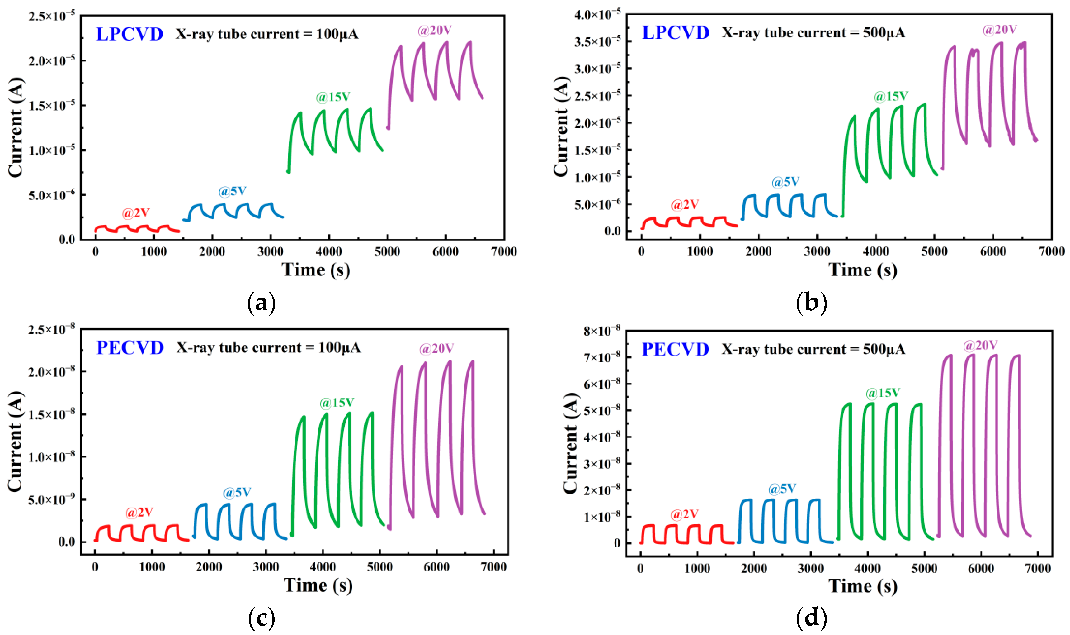
Figure 7, respectively, shows the I–t response characteristics (transient response characteristics) of X-ray detectors fabricated by LPCVD and PECVD at different X-ray tube currents (100 and 500 μA) and bias voltages. As shown in Figure 7, PECVD device maintain an extremely low baseline and smaller drift, quickly entering a steady state and maintaining a flat platform, demonstrating better temporal stability and baseline reproducibility. LPCVD device response curves show slight time-dependent rise. These differences may originate from defect states and interface barrier variations caused by deposition processes: higher carrier density and lower contact barriers form in LPCVD devices, enhancing drift current while amplifying dark current; leakage current is effectively suppressed due to higher barriers or lower shallow donor concentrations in PECVD devices. The photocurrent of both detectors increases with the increase in X-ray tube current. Meanwhile, under strong electric field, the photocurrent increases significantly with the increase in bias voltage. This is related to the high carrier collection efficiency of devices under strong electric fields, where photoconductivity gain can be defined as G = τl/τT, where τT = L/μE (L is the electrode spacing, μ is the carrier mobility, E is the electric field), and τₗ is the carrier lifetime [46]. Intrinsic defects in Ga2O3 (such as oxygen vacancies) can extend the carrier lifetime τl, thereby increasing G. At the same time, the increase in electric field strength reduces τT, leading to an increase in G, which significantly enhances the photocurrent as the bias increases.
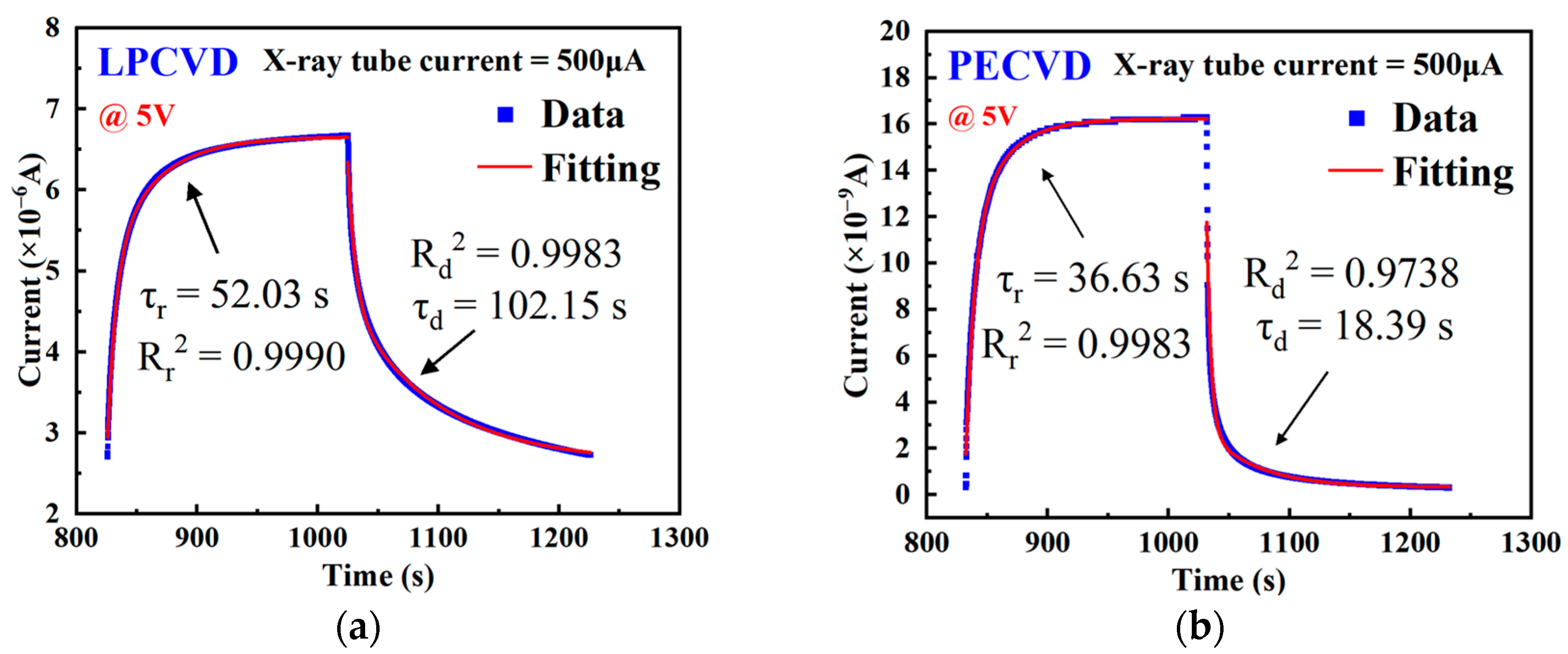
The photocurrent response time dependency curves of β-Ga2O3 X-ray detectors fabricated by LPCVD and PECVD under an X-ray tube current of 500 μA and a 5 V bias are shown in Figure 8a,b, respectively. The response time (τr) and recovery time (τd) were calculated by double exponential fitting of the I–t characteristic curves [34]:
I t   =   I 0   +   A 1 e t / τ r   +   A 2 e t / τ d ,
Both types of devices exhibit varying degrees of response/recovery hysteresis, indicating the presence of persistent photoconductivity (PPC). Both types of devices exhibit different degrees of response/recovery hysteresis, indicating the presence of persistent photoconductivity (PPC). Under X-ray excitation, high-energy electrons not only directly generate electron-hole pairs [42] but also promote the multi-step ionization of VO0 state oxygen vacancies to VO1+ and VO2+ states, possibly forming more positively charged deep capture centers Vo3+. These deep positive centers inhibit hole refilling and delay recombination, resulting in long-lifetime tails and slow recovery [24,47,48,49,50]. Since the formation and stepwise ionization of VO0 state oxygen vacancies require a longer time to reach dynamic equilibrium, the improvement in response speed is limited. Devices fabricated by LPCVD exhibit higher steady-state photocurrent and slower response/recovery times (τr = 52.03 s, τd = 102.15 s), reflecting persistent photoconductivity caused by deep traps, whereas devices fabricated by PECVD have lower steady-state photocurrent but faster response/recovery time (τr = 36.63 s, τd = 18.39 s), which also indicates that the defects in PECVD films are dominated by shallow traps. The R2 values for the double-exponential fitting of all samples are greater than 0.97, indicating a very high degree of agreement between the fitting curves and the experimental data. This can indirectly confirm the credibility of the carrier lifetime parameters.
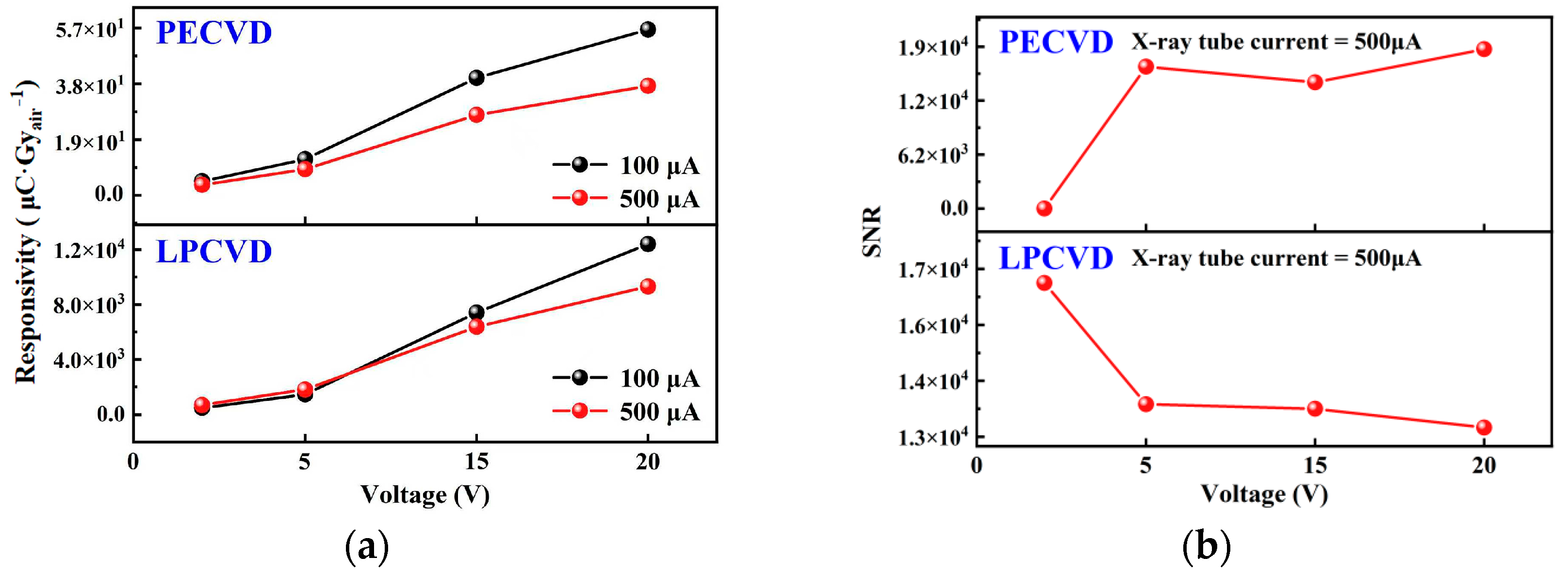
In order to study the dose-dependent photoresponse characteristics of Ga2O3-based X-ray detectors, the responsivity of the device under different X-ray dose rates was calculated, and the influence of bias voltage on the responsivity was investigated, as shown in Figure 9a. Responsivity is defined as the ratio of net photocurrent to incident dose rate [44]:
R   =   I X - r a y     I d a r k D ,
As shown in Figure 9a, the responsivity R of both detectors increases with increasing bias. However, as the tube current increases (i.e., the dose rate increases), the responsivity of both X-ray detectors slightly decreases. This is because the increased number of carriers excited by high-dose X-rays leads to a higher probability of carrier recombination, reflecting the sublinear gain compression due to elevated recombination probability at high carrier density.
The SNR can be expressed using the formula [25]:
S N R   =   I s i g n a l I n o i s e ,
I s i g n a l   =   I ¯ X - r a y     I ¯ d a r k ,
I noise   =   1 N i N I i     I ¯ X - r a y 2 ,
where I ¯ X - r a y is the average photocurrent under X-ray irradiation; I ¯ d a r k is the average dark current; N is the number of photocurrent data points under X-ray irradiation; i is an integer ranging from 1 to N; and Ii is the irradiation steady-state photocurrent sampling point.
The SNR of the device fabricated by PECVD and LPCVD shows opposite trends with increasing bias in Figure 9b. This suggests that the emission/recapture fluctuation of deep traps (G-R and 1/f noise components) in LPCVD devices at high fields increases faster than the optical signal gain and also indicates that there may be more deep-level traps in the thin film grown by LPCVD. It also indicates that there may be more deep-level traps present in the thin films grown by LPCVD. In contrast, devices fabricated by PECVD are dominated by shallow traps, and the noise increases more slowly with the bias voltage.
According to the International Union of Pure and Applied Chemistry (IUPAC), the low dose rate detection limit (LoDmin) corresponding to an SNR of three generated by X-ray detectors is considered its detection limit.
L o D min   =   3 I n o i s e S A
The detection limit LoDmin of the detector fabricated by LPCVD is calculated from the above equation to be 57.07 nGyair s−1, which is significantly higher than 30.13 nGyair s−1 of the detector fabricated by PECVD. These suggest that the detector fabricated by PECVD has greater advantages in scenarios requiring precise detection of low doses or a wide dynamic range under high bias voltage. Moreover, it has a shorter recovery time, lower noise, and is better suited for applications in rapid measurement and stable calibration scenarios.
The comprehensive performance of various X-ray detectors with different preparation processes and equivalent thicknesses in recent years is summarized in Table 2. Compared to β-Ga2O3 or other semiconductor X-ray detectors in the literature that rely on hundreds to thousands of micrometers of thickness and high reverse bias to achieve limited sensitivity, this work achieves a high normalized sensitivity of 3.539 × 10⁵ μCGyair−1 cm−2 μm−1 under only 20 V bias with ultra-thin film (≈0.29 µm), while PECVD film maintains a low detection limit of 30.13 nGyair s−1 at low bias voltage.

4. Conclusions

In summary, β-Ga2O3 thin films were grown on c-plane sapphire by using LPCVD and PECVD techniques, and MSM-type X-ray detectors were fabricated. It is demonstrated that the films grown by LPCVD were thin (289 nm), where slower surface kinetics favor lateral grain coalescence and reduced mosaic tilt (narrower rocking curve), while PECVD plasma activation induces rapid multi-site nucleation and columnar advancement, increasing tilt dispersion yet improving thickness scalability and film densification.
Both films are single-phase, (−201) oriented β-Ga2O3. The film grown by PECVD yields a higher O/Ga atomic ratio (closer to stoichiometric) and a slight Ga 3d binding energy shift, indicating more uniform local electrostatic environments and a shallower trap ensemble relative to the deeper trap population inferred for LPCVD.
For the LPCVD-grown film, despite its submicron thickness, it achieves high (normalized) sensitivity (3.539 × 10⁵ μCGyair−1 cm−2 μm−1 at 20 V) through deep trap-extended carrier lifetime, which boosts photoconductive gain (G = τl/τT). However, it exhibits larger persistent photoconductivity, slower decay (τd = 102.15 s), and SNR degradation at high bias due to trap emission/retrapping noise. The device fabricated by PECVD exhibits superior calibratability and application predictability owing to its lower dark current, linear bias scalability of SNR, faster transient (τd = 18.39 s), and superior minimum detectable dose (30.13 nGyair s−1), making it preferable for low-dose scenarios. Dual exponential transient fits and XPS oxygen sub-peak ratios support a model where progressive oxygen vacancy ionization VO0→VO1+/VO2+ under X-ray fields sustain long-lived photoconductivity in deep-trap dominant films; conversely, limiting deep trap density shifts operation toward rapid, low-noise regimes.
These insights motivate a hybrid optimization path: moderating deep trap density via post-oxidation and mild compensatory dopants while preserving sufficient shallow traps for controlled gain may reconcile sensitivity and speed. Meanwhile, it is also demonstrated that precise control of deposition processes and trap engineering can achieve competitive dose rate response within limited thickness, laying the foundation for subsequent pixilation and low-power array integration in medical imaging, industrial inspection, and other field applications.

Author Contributions

Methodology, L.Y. and H.Z.; investigation, L.Y. and H.Z.; data curation, L.Y., D.N., Y.Z., X.L. and H.Z.; writing—original draft preparation, L.Y. and H.Z.; writing—review and editing, H.Z. and L.Y.; supervision, H.Z.; project administration, L.Y.; funding acquisition, L.Y., H.Z., J.Z. and X.Z. All authors have read and agreed to the published version of the manuscript.

Funding

This research was funded by the Project of College Student Innovation and Entrepreneurship Training Program of China (No. S202410128015, Inner Mongolia Autonomous Region-level), the National Natural Science Foundation of China (Grant Nos. 12264035, 11864029, 62264013, and 62364014), the Natural Science Foundation of Inner Mongolia Autonomous Region of China (Grant No. 2024LHMS01013), and the Program for Young Talents of Science and Technology in Universities of Inner Mongolia Autonomous Region of China (Grant No. NJYT24065).

Data Availability Statement

The datasets generated and/or analyzed during the current study are available from the corresponding authors upon reasonable request.

Acknowledgments

The authors would like to thank Kexiong Zhang, Ku Liu, and Dalin Guo at the School of Integrated Circuits, Dalian University of Technology, for their assistance with the X-ray detector experimental measurements. During the preparation of this manuscript, the author(s) used ChatGPT version 4.0 and DeepSeek V3 to translate specific technical terms and improve readability and language quality. The authors have reviewed and edited the output and take full responsibility for the content of this publication.

Conflicts of Interest

The authors declare no conflicts of interest.

References

  1. Kim, Y.C.; Kim, K.H.; Son, D.-Y.; Jeong, D.-N.; Seo, J.-Y.; Choi, Y.S.; Han, I.T.; Lee, S.Y.; Park, N.-G. Printable Organometallic Perovskite Enables Large-Area, Low-Dose X-Ray Imaging. Nature 2017, 550, 87–91. [Google Scholar] [CrossRef]
  2. Suchikova, Y.; Nazarovets, S.; Popov, A.I. Ga2O3 Solar-Blind Photodetectors: From Civilian Applications to Missile Detection and Research Agenda. Opt. Mater. 2024, 157, 116397. [Google Scholar] [CrossRef]
  3. Chen, M.; Zhang, Z.; Zhan, R.; She, J.; Deng, S.; Xu, N.; Chen, J. Fast-Response X-Ray Detector Based on Nanocrystalline Ga2O3 Thin Film Prepared at Room Temperature. Appl. Surf. Sci. 2021, 554, 149619. [Google Scholar] [CrossRef]
  4. Ouyang, X.; Zhang, S.; Bai, T.; Chen, Z.; Deng, Y.; Zhou, L.; Song, X.; Chen, H.; Lai, Y.; Lu, X.; et al. Performance Degradation of Ga2O3-Based X-Ray Detector Under Gamma-Ray Irradiation. Micromachines 2025, 16, 339. [Google Scholar] [CrossRef]
  5. Langpoklakpam, C.; Rana, S.; Hsieh, C.; Singh, J.P.; Lee, P.; Horng, R.; Tu, C.; Kuo, H. State-of-the-Art Solar Blind and X-Ray Photodetectors Based on Gallium Oxide. Adv. Photonics Res. 2025, 2500008. [Google Scholar] [CrossRef]
  6. Matt, G.J.; Levchuk, I.; Knüttel, J.; Dallmann, J.; Osvet, A.; Sytnyk, M.; Tang, X.; Elia, J.; Hock, R.; Heiss, W.; et al. Sensitive Direct Converting X-Ray Detectors Utilizing Crystalline CsPbBr3 Perovskite Films Fabricated via Scalable Melt Processing. Adv. Mater. Interfaces 2020, 7, 1901575. [Google Scholar] [CrossRef]
  7. Ye, F.; Lin, H.; Wu, H.; Zhu, L.; Huang, Z.; Ouyang, D.; Niu, G.; Choy, W.C.H. High-Quality Cuboid CH3NH3PbI3 Single Crystals for High Performance X-Ray and Photon Detectors. Adv. Funct. Mater. 2019, 29, 1806984. [Google Scholar] [CrossRef]
  8. Li, Y.; Wang, X.; Liang, J.; Zhang, L.; Zhang, J. Recent Progress in Direct X-Ray Detectors Based on Metal Oxide Wide Bandgap Semiconductors: A Review. IEEE Sens. J. 2024, 24, 38569–38583. [Google Scholar] [CrossRef]
  9. Venkata Prasad, C.; Labed, M.; Alam Shamim Shaikh, M.T.; Min, J.Y.; Vu Nguyen, T.H.; Song, W.; Kim, K.J.; Rim, Y.S. Ga2O3-Based X-Ray Detector and Scintillators: A Review. Mater. Today Phys. 2023, 35, 101095. [Google Scholar] [CrossRef]
  10. Zhao, J.; Wang, X.; Li, Y.; Cheng, Q.; Onwudiwe, D.C.; Bae, B.S.; Ertuğrul, M.; Zhu, Y.; Lei, W.; Xu, X. Substance Discrimination Imaging Derived from Switchable Soft and Hard X-ray Sensing in Direct X-ray Detector. InfoMat 2025, 7, e12632. [Google Scholar] [CrossRef]
  11. Hang, S. Research on X-Ray Irradiation Detection Based on Amorphous Gallium Oxide. Master’s Thesis, University of Electronic Science and Technology of China, Chengdu, China, 2023. [Google Scholar]
  12. Geng, X.; Chen, Y.; Li, Y.; Ren, J.; Dun, G.; Qin, K.; Lin, Z.; Peng, J.; Tian, H.; Yang, Y.; et al. Lead-Free Halide Perovskites for Direct X-Ray Detectors. Adv. Sci. 2023, 10, 2300256. [Google Scholar] [CrossRef]
  13. Xu, X.; Qian, W.; Xiao, S.; Wang, J.; Zheng, S.; Yang, S. Halide Perovskites: A Dark Horse for Direct X-ray Imaging. EcoMat 2020, 2, e12064. [Google Scholar] [CrossRef]
  14. Wronski, M.M.; Rowlands, J.A. Direct-conversion Flat-panel Imager with Avalanche Gain: Feasibility Investigation for HARP-AMFPI. Med. Phys. 2008, 35, 5207–5218. [Google Scholar] [CrossRef] [PubMed]
  15. Kasap, S.; Frey, J.B.; Belev, G.; Tousignant, O.; Mani, H.; Greenspan, J.; Laperriere, L.; Bubon, O.; Reznik, A.; DeCrescenzo, G.; et al. Amorphous and Polycrystalline Photoconductors for Direct Conversion Flat Panel X-Ray Image Sensors. Sensors 2011, 11, 5112–5157. [Google Scholar] [CrossRef] [PubMed]
  16. Basiricò, L.; Ciavatti, A.; Fraboni, B. Solution-Grown Organic and Perovskite X-Ray Detectors: A New Paradigm for the Direct Detection of Ionizing Radiation. Adv. Mater. Technol. 2021, 6, 2000475. [Google Scholar] [CrossRef]
  17. Chaudhari, R.; RaviKant, C. A Review on BiI3 Perovskites and Composites for Direct X-Ray Detection. Sens. Actuators Phys. 2022, 346, 113863. [Google Scholar] [CrossRef]
  18. Shikhaliev, P.M. Tilted Angle CZT Detector for Photon Counting/Energy Weighting X-Ray and CT Imaging. Phys. Med. Biol. 2006, 51, 4267–4287. [Google Scholar] [CrossRef]
  19. Negre, J.P.; Rubbelynck, C. Application of Fast CVD Diamond Photoconductor Detectors to MeV X-Ray Metrology for the AIRIX Flash Radiographic Facility. Nucl. Instrum. Methods Phys. Res. Sect. A Accel. Spectrometers Detect. Assoc. Equip. 2000, 451, 638–650. [Google Scholar] [CrossRef]
  20. Li, Q.; Beilicke, M.; Lee, K.; Garson Iii, A.; Guo, Q.; Martin, J.; Yin, Y.; Dowkontt, P.; De Geronimo, G.; Jung, I. Study of Thick CZT Detectors for X-Ray and Gamma-Ray Astronomy. Astropart. Phys. 2011, 34, 769–777. [Google Scholar] [CrossRef]
  21. Kasap, S.O. X-Ray Sensitivity of Photoconductors: Application to Stabilized a-Se. J. Phys. Appl. Phys. 2000, 33, 2853–2865. [Google Scholar] [CrossRef]
  22. Lee, S.C.; Jeon, H.B.; Kang, K.H.; Kim, B.B.; Park, H. Study of Silicon Photodiode Performance for X-Ray Detector in Cargo System. Nucl. Instrum. Methods Phys. Res. Sect. A Accel. Spectrometers Detect. Assoc. Equip. 2018, 912, 350–353. [Google Scholar] [CrossRef]
  23. Pearton, S.J.; Yang, J.; Cary, P.H.; Ren, F.; Kim, J.; Tadjer, M.J.; Mastro, M.A. A Review of Ga2O3 Materials, Processing, and Devices. Appl. Phys. Rev. 2018, 5, 011301. [Google Scholar] [CrossRef]
  24. Kim, J.; Pearton, S.J.; Fares, C.; Yang, J.; Ren, F.; Kim, S.; Polyakov, A.Y. Radiation Damage Effects in Ga2O3 Materials and Devices. J. Mater. Chem. C 2019, 7, 10–24. [Google Scholar] [CrossRef]
  25. Li, Z.; Tang, H.; Xu, J.; Liu, B. Research Progress of Ultra-Wide Band Gap Semiconductor Ga2O3-Based X-Ray Detectors. J. Synth. Cryst. 2022, 51, 523–537, 570. [Google Scholar] [CrossRef]
  26. Zhang, H.; Niu, D.; Yang, J.; Zhang, X.; Zhu, J.; Li, W. β-Ga2O3 Thin Films via an Inorganic Sol–Gel Spin Coating: Preparation and Characterization. Nanomaterials 2025, 15, 277. [Google Scholar] [CrossRef]
  27. Liu, J.; Deng, H.; Zhao, X.; Wu, C.; Zhang, H.; Lang, F. Investigation of the Nano and Micromechanical Performance of β-Ga2O3 Epitaxial Films on Sapphire Using Nanoindentation. Vacuum 2024, 227, 113413. [Google Scholar] [CrossRef]
  28. Vashishtha, P.; Jain, S.K.; Prajapat, P.; Verma, A.K.; Aggarwal, N.; Murdoch, B.J.; Walia, S.; Gupta, G. A Self-Driven Bidirectional Photocurrent Photodetector for Optically Controlled Logic Gates Utilizes a GaN-Nanowall Network. ACS Appl. Opt. Mater. 2024, 2, 1353–1359. [Google Scholar] [CrossRef]
  29. Lu, X.; Zhou, L.; Chen, L.; Ouyang, X.; Liu, B.; Xu, J.; Tang, H. Schottky X-Ray Detectors Based on a Bulk β-Ga2O3 Substrate. Appl. Phys. Lett. 2018, 112, 103502. [Google Scholar] [CrossRef]
  30. Hany, I.; Yang, G.; Chung, C.-C. Fast X-Ray Detectors Based on Bulk β-Ga2O3 (Fe). J. Mater. Sci. 2020, 55, 9461–9469. [Google Scholar] [CrossRef]
  31. Chen, J.; Tang, H.; Liu, B.; Zhu, Z.; Gu, M.; Zhang, Z.; Xu, Q.; Xu, J.; Zhou, L.; Chen, L.; et al. High-Performance X-Ray Detector Based on Single-Crystal β-Ga2O3:Mg. ACS Appl. Mater. Interfaces 2021, 13, 2879–2886. [Google Scholar] [CrossRef]
  32. Li, Z.; Chen, J.; Tang, H.; Zhu, Z.; Gu, M.; Xu, J.; Chen, L.; Ouyang, X.; Liu, B. Band Gap Engineering in β-Ga2O3 for a High-Performance X-Ray Detector. ACS Appl. Electron. Mater. 2021, 3, 4630–4639. [Google Scholar] [CrossRef]
  33. Zhong, T.; Yu, s.; Zhao, X.; Ding, M.; Liang, F.; Fang, S.; Zhang, Z.; Hou, X.; Sun, H.; Xu, G.; et al. High-performance Solar-blind and X-ray Detector Based on Ultra-thin Gallium Oxide Film Grown by MOCVD (Invited). Acta Photonica Sin. 2021, 50, 213–224. [Google Scholar]
  34. Chen, Y.; Niu, S.; Li, Y.; Dou, W.; Yang, X.; Shan, C.; Shen, G. Flexible Single Microwire X-Ray Detector with Ultrahigh Sensitivity for Portable Radiation Detection System. Adv. Mater. 2024, 36, 2404656. [Google Scholar] [CrossRef]
  35. Liang, H.; Tang, X.; Shao, H.; Zhu, R.; Deng, S.; Zhan, X.; Zhu, T.; Wang, J.; Zhang, J.; Zhang, G.; et al. Retina-Inspired X-Ray Optoelectronic Synapse Using Amorphous Ga2O3 Thin Film. Adv. Sci. 2024, 11, 2410761. [Google Scholar] [CrossRef]
  36. Wang, Z.; Wang, X.; Ma, Y.; Sun, J.; Wang, S.; Jia, Y.; He, Y.; Lu, X.; Lin, D.; Zhu, Q.; et al. Highly Reliable and Sensitive Solar-Blind Ultraviolet and X-Ray Detector Based on ALD Deposited Amorphous Ga2O3. IEEE Electron Device Lett. 2024, 45, 1879–1882. [Google Scholar] [CrossRef]
  37. Kim, M.; Kim, S.; Park, J.; Cho, H.G.; Gihm, S.H.; Jeon, D.; Hwang, W.S. Heteroepitaxial α-Ga2O3 Thin Film-Based X-Ray Detector with Metal–Semiconductor–Metal Structure. Phys. Status Solidi RRL—Rapid Res. Lett. 2025, 19, 2400193. [Google Scholar] [CrossRef]
  38. Gan, Z.; Li, C.; Hou, X.; Yu, S.; Bai, S.; Peng, Z.; Han, K.; Zou, Y.; Wang, Z.; Zhao, X.; et al. Sensitive Direct Converting Thin Film X-Ray Detector Utilizing β-Ga2O3 Fabricated via MOCVD. Appl. Phys. Lett. 2024, 125, 191102. [Google Scholar] [CrossRef]
  39. Zhang, H.; Niu, D.; Zhao, X.; Du, Z.; Cui, X. Solid-State Source Plasma Enhanced Chemical Vapor Deposition Equipment and Method CN. Patent Application No. 202411489122.1, 24 October 2024. [Google Scholar]
  40. Kramer, B. Electronic Structure and Optical Properties of Amorphous Germanium and Silicon. Phys. Status Solidi B 1971, 47, 501–510. [Google Scholar] [CrossRef]
  41. Kumarbekov, K.K.; Kakimov, A.B.; Karipbayev, Z.T.; Kassymzhanov, M.T.; Brik, M.G.; Ma, C.; Piasecki, M.; Suchikova, Y.; Kemere, M.; Konuhova, M. Temperature-Dependent Luminescence of Europium-Doped Ga2O3 Ceramics. Opt. Mater. X 2025, 25, 100392. [Google Scholar] [CrossRef]
  42. Xu, Y.; Cheng, Y.; Li, Z.; Chen, D.; Xu, S.; Feng, Q.; Zhu, W.; Zhang, Y.; Zhang, J.; Zhang, C.; et al. Ultrahigh-Performance Solar-Blind Photodetectors Based on High Quality Heteroepitaxial Single Crystalline β-Ga2O3 Film Grown by Vacuumfree, Low-Cost Mist Chemical Vapor Deposition. Adv. Mater. Technol. 2021, 6, 2001296. [Google Scholar] [CrossRef]
  43. Kaur, D.; Dahiya, R.; Shivani; Kumar, M. Origin of Near-Failure in Au Contacts to Polycrystalline β-Ga2O3 at High Temperatures Using Interfacial Studies. Appl. Phys. Lett. 2024, 124, 151601. [Google Scholar] [CrossRef]
  44. Wang, J.; Zhou, L.; Lu, X.; Chen, L.; Chen, Z.; Zou, X.; Wang, G.; Yang, B.; Ouyang, X. Pulsed X-Ray Detector Based on an Unintentionally-Doped High Resistivity ε-Ga2O3 Film. IEEE Photonics Technol. Lett. 2023, 35, 89–92. [Google Scholar] [CrossRef]
  45. Vo, T.H.; Kim, S.; Kim, M.; Cho, H.G.; Gihm, S.H.; Park, J.-H.; Jeon, D.-W.; Hwang, W.S. Charge Neutral Point Shift of a 700 Nm-Thick α-Ga2O3 Thin-Film Detector under Soft X-Ray Irradiation. ACS Appl. Electron. Mater. 2024, 6, 5973–5978. [Google Scholar] [CrossRef]
  46. Yu, S.; Liu, Y.; Hou, X.; Ding, M.; Zou, Y.; Guan, Y.; Wu, Z.; Zhao, X.; Hu, Q.; Xu, G.; et al. Stable Ga2O3 Soft X-Ray Detector with Ultrahigh Responsivity. Appl. Phys. Lett. 2024, 124, 181111. [Google Scholar] [CrossRef]
  47. Ahn, S.; Song, I.; Jeon, S.; Jeon, Y.W.; Kim, Y.; Kim, C.; Ryu, B.; Lee, J.; Nathan, A.; Lee, S.; et al. Metal Oxide Thin Film Phototransistor for Remote Touch Interactive Displays. Adv. Mater. 2012, 24, 2631–2636. [Google Scholar] [CrossRef] [PubMed]
  48. Jang, J.T.; Park, J.; Ahn, B.D.; Kim, D.M.; Choi, S.-J.; Kim, H.-S.; Kim, D.H. Study on the Photoresponse of Amorphous In–Ga–Zn–O and Zinc Oxynitride Semiconductor Devices by the Extraction of Sub-Gap-State Distribution and Device Simulation. ACS Appl. Mater. Interfaces 2015, 7, 15570–15577. [Google Scholar] [CrossRef] [PubMed]
  49. Lee, M.; Lee, W.; Choi, S.; Jo, J.; Kim, J.; Park, S.K.; Kim, Y. Brain-Inspired Photonic Neuromorphic Devices Using Photodynamic Amorphous Oxide Semiconductors and Their Persistent Photoconductivity. Adv. Mater. 2017, 29, 1700951. [Google Scholar] [CrossRef]
  50. Jeon, S.; Ahn, S.-E.; Song, I.; Kim, C.J.; Chung, U.-I.; Lee, E.; Yoo, I.; Nathan, A.; Lee, S.; Ghaffarzadeh, K.; et al. Gated Three-Terminal Device Architecture to Eliminate Persistent Photoconductivity in Oxide Semiconductor Photosensor Arrays. Nat. Mater. 2012, 11, 301–305. [Google Scholar] [CrossRef]
  51. Yang, Y.; Fan, Z.; He, B.; Jia, Z.; Zhao, H.; Xiong, P.; Liu, Y.; Dang, W.; Wang, J.; Zheng, H.; et al. Solution-Processed Sb2−xBixS3 Thick Junctions for Stable, Low-Noise, and Sensitive X-Ray Detection. Device 2024, 2, 100518. [Google Scholar] [CrossRef]
  52. Peng, Z.; Hou, X.; Han, Z.; Gan, Z.; Li, C.; Wu, F.; Bai, S.; Yu, S.; Liu, Y.; Yang, K.; et al. Ga2O3 Photon-Controlled Diode for Sensitive DUV/X-Ray Detection and High-Resolution Array Imaging Application. Adv. Funct. Mater. 2024, 34, 2405277. [Google Scholar] [CrossRef]
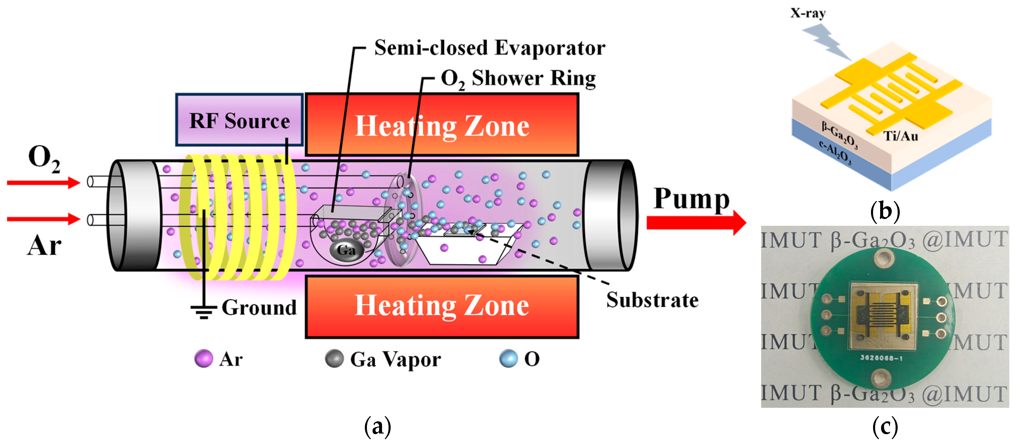
Figure 1. (a) Experimental setup for β-Ga2O3 thin film growth, (b) schematic diagram, and (c) physical image of the fabricated MSM-type detector.
Nanomaterials 15 01360 g001
Figure 2. SEM surface topography; the insets show the corresponding cross-section: (a) LPCVD, (b) PECVD.
Nanomaterials 15 01360 g002
Figure 3. (a) Transmittance spectra and calculated optical bandgap of β-Ga2O3 thin films grown by LPCVD and PECVD. (b) Photoluminescence excitation spectra of the films grown via LPCVD and PECVD. (c) X-ray diffraction spectra. (d) Rocking curve of (−201) crystal plane of β-Ga2O3 thin films.
Nanomaterials 15 01360 g003
Figure 4. XPS spectra of β-Ga2O3 thin films. (a) O 1s core-level spectra of β-Ga2O3 thin film grown by LPCVD. (b) O 1s core-level spectra of β-Ga2O3 thin film grown by PECVD. (c) Comparison of Ga 3d core-level spectra.
Nanomaterials 15 01360 g004
Figure 5. I–V characteristic curves of the detector under X-ray irradiation at different tube currents: (a) LPCVD; (b) PECVD; (c) logarithmic I–V characteristics of the detector in dark state and under X-ray irradiation at room temperature; (d) dose-rate dependent photocurrent of β-Ga2O3 MSM X-ray detectors fabricated by LPCVD and PECVD at 20 V bias.
Nanomaterials 15 01360 g005
Figure 6. The variation in net induced current and sensitivity at different bias voltages of 2 V, 5 V, 15 V, and 20 V at a fixed X-ray tube current of 500μA: (a) LPCVD, (b) PECVD.
Nanomaterials 15 01360 g006
Figure 7. Transient response characteristics (I–t) of the X-ray detectors fabricated by (a,b) LPCVD and (c,d) PECVD at bias voltages of 2, 5, 15, and 20 V. X-ray tube currents are 100 μA for (a,c) and 500 μA for (b,d). The different colored lines in each figure represent the response characteristics at 2 V, 5 V, 15 V, and 20 V bias, respectively.
Nanomaterials 15 01360 g007
Figure 8. Time-resolved photocurrent of MSM β-Ga2O3 X-ray detectors fabricated by (a) LPCVD and (b) PECVD at a tube current of 500 μA and bias of 5 V.
Nanomaterials 15 01360 g008
Figure 9. (a) The responsivity of the detectors fabricated by LPCVD and PECVD varies with the bias voltage under X-ray irradiation at different tube currents. (b) The signal-to-noise ratio (SNR) of the detectors fabricated by LPCVD and PECVD varies with the bias voltage at an X-ray tube current of 500 μA.
Nanomaterials 15 01360 g009
Table 1. X-ray dose rate corresponding to different X-ray tube currents.
ItemValue
X-ray tube voltage (kV)40
X-ray tube current (μA)100200300400500
X-ray dose rate (μGy/s)315.5700.21166.01638.21951.0
Table 2. Comparison of comprehensive performance of various X-ray detectors with different methods and equivalent thicknesses.
MaterialsGrowth MethodDevice TypeThickness
(μm)
Snorm
(μCGyair−1 cm−2 μm−1)
LoDmin
(nGyair s−1)
Ref.
β-Ga2O3LPCVDMSM0.2893.539 × 105 @ 20 V57.07this work
β-Ga2O3PECVDMSM1.5272 @ 20 V30.13this work
MAPbI3/MAPbBr3Solution MethodMSM10608.197 @ 60 keV/[10]
Sb1.9Bi0.1S3Sol–gel Methodp-i-n40000.625 @ −20 V89[51]
α-Ga2O3ALDMSM0.051.904 × 104 @ 15 V11.23[36]
α-Ga2O3HVPEMSM0.719.57 @10 V/[37]
α-Ga2O3RF magnetron sputteringMSM0.364.56 × 105 @ 10 V/[35]
β-Ga2O3MOCVDMSM0.2581.442 × 106 @ 40 V/[38]
β-Ga2O3MOCVDMSM0.3193.86 × 105 @ 50 V/[52]
β-Ga2O3 MicrowireCVDMSM 5.9 × 10⁵ @ 20 V67.4[34]
UID β-Ga2O3Guided-mode MethodVertical Schottky diode4000.165 @ −15 V/[31]
β-Ga2O3:MgFloat-Zone GrowthMSM10000.339 @ −1000 V<6.95 × 10⁴[31]
β-Ga2O3:AlOptical Floating ZoneMSM10000.852 @ 350 V9.8 × 103[32]
Disclaimer/Publisher’s Note: The statements, opinions and data contained in all publications are solely those of the individual author(s) and contributor(s) and not of MDPI and/or the editor(s). MDPI and/or the editor(s) disclaim responsibility for any injury to people or property resulting from any ideas, methods, instructions or products referred to in the content.