Next Article in Journal
Fabrication of Large-Core Multicore Fiber Bragg Gratings Based on Femtosecond Laser Direct Writing Technology
Previous Article in Journal
Comparative Study of Free and Encapsulated Hypocrellin B on Photophysical-Chemical Properties, Cellular Uptake, Subcellular Distribution, and Phototoxicity
 
 
Due to scheduled maintenance work on our database systems, there may be short service disruptions on this website between 10:00 and 11:00 CEST on June 14th.
Article

Minimizing Color Difference in AAO-Based Coatings for Urban Camouflage

Chemical Defense Institute, Academy of Military Sciences, Beijing 102205, China
*
Author to whom correspondence should be addressed.
Nanomaterials 2025, 15(12), 890; https://doi.org/10.3390/nano15120890
Submission received: 24 April 2025 / Revised: 3 June 2025 / Accepted: 4 June 2025 / Published: 9 June 2025
(This article belongs to the Section Synthesis, Interfaces and Nanostructures)

Abstract

:
We explored anodic aluminum oxide (AAO) stealth materials combining low infrared emissivity and visible structural coloration through multi-parameter modulation. Using DC ion gold sputtering and UHV magnetron chromium sputtering, we successfully prepared an AAO stealth material with high-saturation visible structural coloration and low infrared emissivity (ε < 0.17). Quantitative evaluation based on the CIE Lab color difference model indicated that the gold-coated samples had high matching accuracy with PANTONE standard colors ( Δ E a b * < 1.6). The chromium-coated samples had slightly lower matching accuracy ( Δ E a b * < 3.0), but still displayed rich coloration, with color difference within human-perceptible tolerance limits.

1. Introduction

Modern stealth technology is evolving toward fine-tuned camouflage for given targets. Diverse, vibrant background colors are making urban life more interesting. Glass curtain walls, buildings, and bridges diffract bright, high-luminance colors against sunlight or artificial lighting. Visible-light stealth requires modulating the target’s reflection spectrum in the 0.38–0.75 μm range to match background radiation. In urban environments with diverse light sources, the key is to establish a chromaticity space adaptation mechanism. This involves using nanostructures to precisely control the reflection spectrum’s peak intensity, half-width, and color purity of the material, thereby reducing the target–background color difference (ΔE) to below 3 (e.g., CIE Technical Report or ISO/CIE 11664-6:2014 [1]). Since color differences become imperceptible to the human eye when ΔE < 3, minimizing the material’s color difference from the standard color is essential for enhancing visible-light stealth and achieving visual blending. Infrared stealth operates by minimizing the target’s infrared signatures in the atmospheric windows (3–5 μm and 8–14 μm), thereby reducing its contrast against the background. This is typically achieved by reducing the object’s surface temperature or limiting its emissivity [2,3,4]. Anodic aluminum oxide (AAO) is considered an ideal stealth material due to the high reflectivity of its aluminum substrate and its ability to generate visible structural colors through thin-film interference [5,6,7,8]. AAO is produced by anodic oxidation of aluminum, which directly grows an ordered porous oxide layer on an aluminum substrate through artificial induction, overcoming the tendency of pure aluminum to form a passive natural oxide film in air. When the AAO layer is thin enough, not only can the ultralow infrared emissivity of metallic aluminum be retained, but the optical interference intensity can also be controlled by adjusting the pore size. The conditions and extent of pore widening are critical for color control: excessive pore enlargement can delaminate the whole AAO layer due to thinning pore walls; insufficient widening prevents the establishment of thin-film interference on the metal [9,10]. Therefore, further optimizing the visible coloration of AAO materials through processes such as electrolytic coloring, atomic layer deposition, and metal sputtering has attracted wide attention among researchers [11,12,13,14,15,16,17,18,19].
Lee et al. [20] systematically investigated the optical behaviors of Ru-coated nanoporous AAO nanostructures in the visible and near-infrared regions through atomic layer deposition. The material displayed brilliant structural colors, in which the color display covered the full visible spectrum. However, the material series showed a maximum average reflectance in the near-infrared regions of approximately 70%, meaning that its infrared stealth performance is not so strong. Xu et al. [21] successfully synthesized a Ag-coated AAO film with a golden visible color through UHV magnetron sputtering. UV–Vis reflectance spectra measurements showed strong absorption in the blue–violet region. Absorption peaks indicated that the golden color came from localized surface plasmonic effects. The visible color of the material did not change with viewing angle. By stripping the AAO layer, they confirmed that AAO nanostructures had a weak contribution to coloration and thus it was impossible to tune the color of the sample by adjusting AAO porous structures. Pashchanka et al. [22] Deposited metallic Pt/Pd alloy and Cr onto nanoporous AAO through magnetron sputtering or thermal evaporation. They achieved bright, saturated coloration across the visible spectrum through interference by adjusting AAO film thickness. Fang et al. [23] deposited gold nanoparticles (Au NPs) onto an anodic aluminum oxide (AAO) template via electron beam evaporation, followed by selective etching of the AAO template with an alkaline solution to retain the gold nanoparticles assembled into hollow pillar structures (NPAHP). Owing to the localized surface plasmon resonance (LSPR) effect of the Au NPs, this material exhibits a black appearance under visible light with high absorbance, enabling seamless blending with the dark background of night or outer space. Concurrently, its low emissivity in the infrared regime effectively suppresses thermal radiation, rendering objects undetectable by infrared detectors. These experiments demonstrate that rich visible colors can be produced in AAO and the chromatic properties of samples can be effectively adjusted by tuning the process parameters. However, these AAO coloring materials are mostly applied in decorative coatings, anti-counterfeiting markers, and optical sensors [24,25,26,27]. Xu and Fang fabricated materials by sputtering or depositing a layer of metal onto an AAO nanohole array structure, then etching away the AAO template. The coloring mechanism is based on the plasmonic resonance effect of metal nanoparticles. However, Xu’s material can only display the color gold, while Fang’s material appears black, indicating a relatively limited range of visible light colors.
In this study, we explored the use of DC ion gold sputtering or UHV magnetron chromium sputtering to reduce the color difference in AAO materials and to improve the matching of their visible colors to standard colors, which were selected from the full range of Pantone standard color cards in this study. By integrating the ability of these AAO coating processes with the low infrared emissivity of aluminum substrate, we prepared a visible–infrared-compatible stealth material with higher color saturation and lower color difference. Given the urban focus of this study’s stealth materials, urban structures and military equipment primarily emit infrared energy in the 8–14 μm long-wave infrared band, so this study emphasizes infrared stealth performance in this band. Through spectral reflectance measurement and colorimetric analysis, we revealed the relationship between metal thin-film microstructures and macroscopic color performance.

2. Materials and Methods

2.1. Materials and Reagents

Materials and reagents used in our study included aluminum sheet (99.99%), gold target (99.99%), chromium target (99.99%), C2H5OH (99.5%, Maclin), H3PO4 (AR > 85%WT, Maclin), CrO3 (99.9%, Maclin), and C2H2O4•2H2O (>99%, Roawn). All reagents were of analytical grade.

2.2. Experimental Methods

We prepared AAO samples by two-step anodization using 0.4 mol/L oxalic acid solution as the electrolyte. The process conditions for two-step anodization are given in Table 1. After primary anodization, we cleaned the samples thoroughly and then immersed them in a mixed acid solution (0.5 mol/L H3PO4 and 0.2 mol/L H2CrO4 mixed at the proportion of 1:1) at 70 °C for 20 min to remove the primary anodic oxide film. Typically, AAO materials prepared in oxalic acid have small micropore diameters. In order to widen pore diameters, we immersed the samples in 0.3 mol/L phosphoric acid solution at 30 °C for 25 min.
We coated the AAO samples prepared in Table 1 by DC ion gold sputtering and UHV magnetron chromium sputtering. Both involved two coating sequences. The first was widening before coating (widening → coating); the second was coating after secondary anodization and then widening pores under the same pore-widening conditions (coating → widening). DC ion gold sputtering was performed at a base pressure of 6 Pa, target-to-substrate spacing of 40 mm (center-to-center), deposition rate of 0.25 nm/s, and coating durations of 10 s, 20 s, and 30 s. UHV magnetron chromium sputtering was performed at a base pressure of <5 × 10⁻⁵ Pa, target-to-substrate holder spacing of 60 mm (center-to-center), deposition rate of 0.12 nm/s, and coating durations of 20 s, 40 s, and 60 s.
Due to the large number of samples coated in this study, the treatment conditions for different samples are briefly labeled in Table 2 below, we marked the widening → coating series as K and the coating → widening series as W:
We observed and analyzed the microstructures of the AAO samples with a scanning electron microscope (SEM, Hitachi SU8010, Tokyo, Japan), measured their infrared emissivity with an infrared spectrometer (FTIR, Nicolet iS50, Waltham, MA, USA), measured their visible-light spectra with a UV–Vis spectrophotometer (UV-Vis, Hitachi UH4150, Tokyo, Japan), analyzed their surface X-ray diffraction with an X-ray diffractometer (XRD, Bruker D8 Advance, Berlin, Germany), examined their surface elemental composition with an energy-dispersive spectrometer (EDS, AXIS Ultra DLD, Kyoto, Japan), and measured their colorimetric values with a colorimeter (Konica Minolta CM-5, Kyoto, Japan).

3. Results and Analysis

3.1. Infrared–Visible-Compatible AAO Material

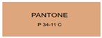
We measured the pre- and post-widening infrared reflectance spectra of samples 1 and 2 prepared in Table 1. According to Kirchhoff’s law, for opaque aluminum foil, the infrared emissivity can be calculated as
ε = 1 β
where ε is the infrared emissivity and β is the reflectivity. As shown in Figure 1, the samples displayed different pre- and post-widening reflectivity over the infrared spectrum. In this study, total hemispherical emissivity was measured using an integrating sphere. For thorough stealth performance evaluation, angle-resolved measurements are recommended. Specifically, sample 1 had much higher overall infrared reflectivity than sample 2 due to shorter anodization duration. Notably, both groups of samples displayed enhanced infrared emissivity after pore widening. Calculations showed a pre- and post-widening average emissivity of 0.083 and 0.076 in the 8–14 μm band for sample 1, compared to 0.115 and 0.109 in the same band for sample 2. This indicates that pore widening influenced surface microstructure, effectively modulating the material’s reflectance over the specific infrared spectrum.
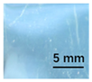
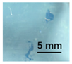
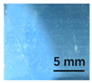
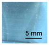
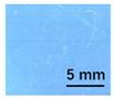
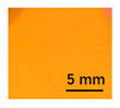
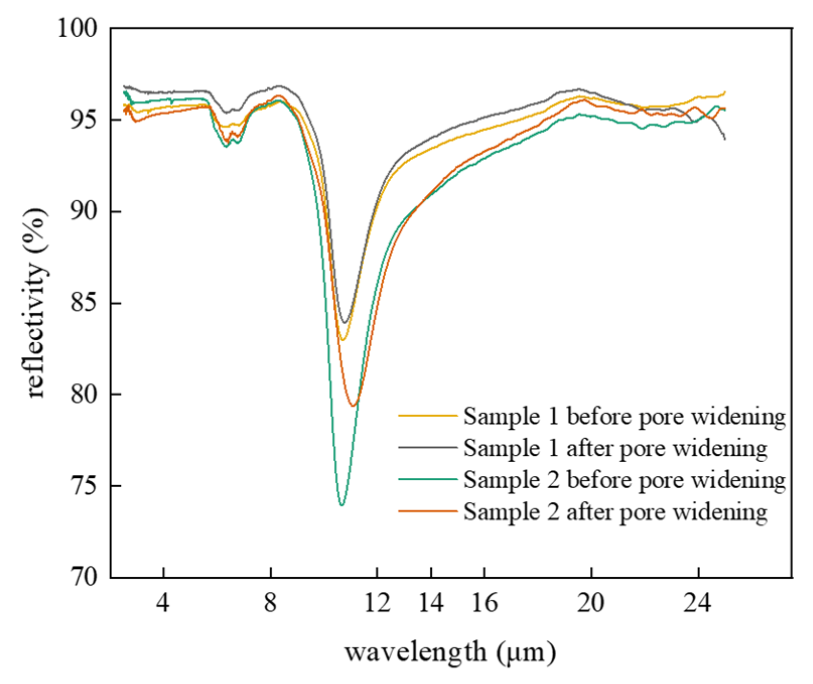
Although the raw AAO samples had the intrinsic coloration over the visible spectrum, their color saturation was too low to be clearly identifiable unless under strong illumination. 
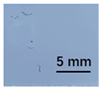
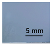
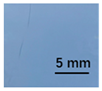
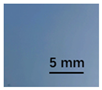
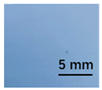
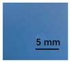
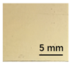
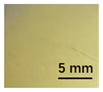
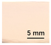
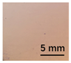
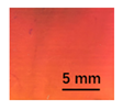
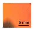
Figure 2 compares the optical properties of the AAO samples prepared under different process conditions: under normal incident light, samples treated under different secondary anodization durations displayed pronounced colorimetric divergence: at the anodization duration t
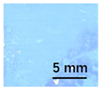
2 = 5 min, the resulted sample 1 appeared pale blue, showing a characteristic peak at 435 nm of the reflectance spectrum; at t2 = 10 min, the resulted sample 2 appeared light pink, showing a spectral reflectance peak at 710 nm (typical red band). Notably, although the 710 nm peak wavelength corresponds to standard red light, the light pink appearance of the sample was possibly attributed to the high reflectance of the aluminum substrate. The superposition of the broadband white light generated by the aluminum substrate through total reflection and red-band spectral components gave rise to light pink coloration.
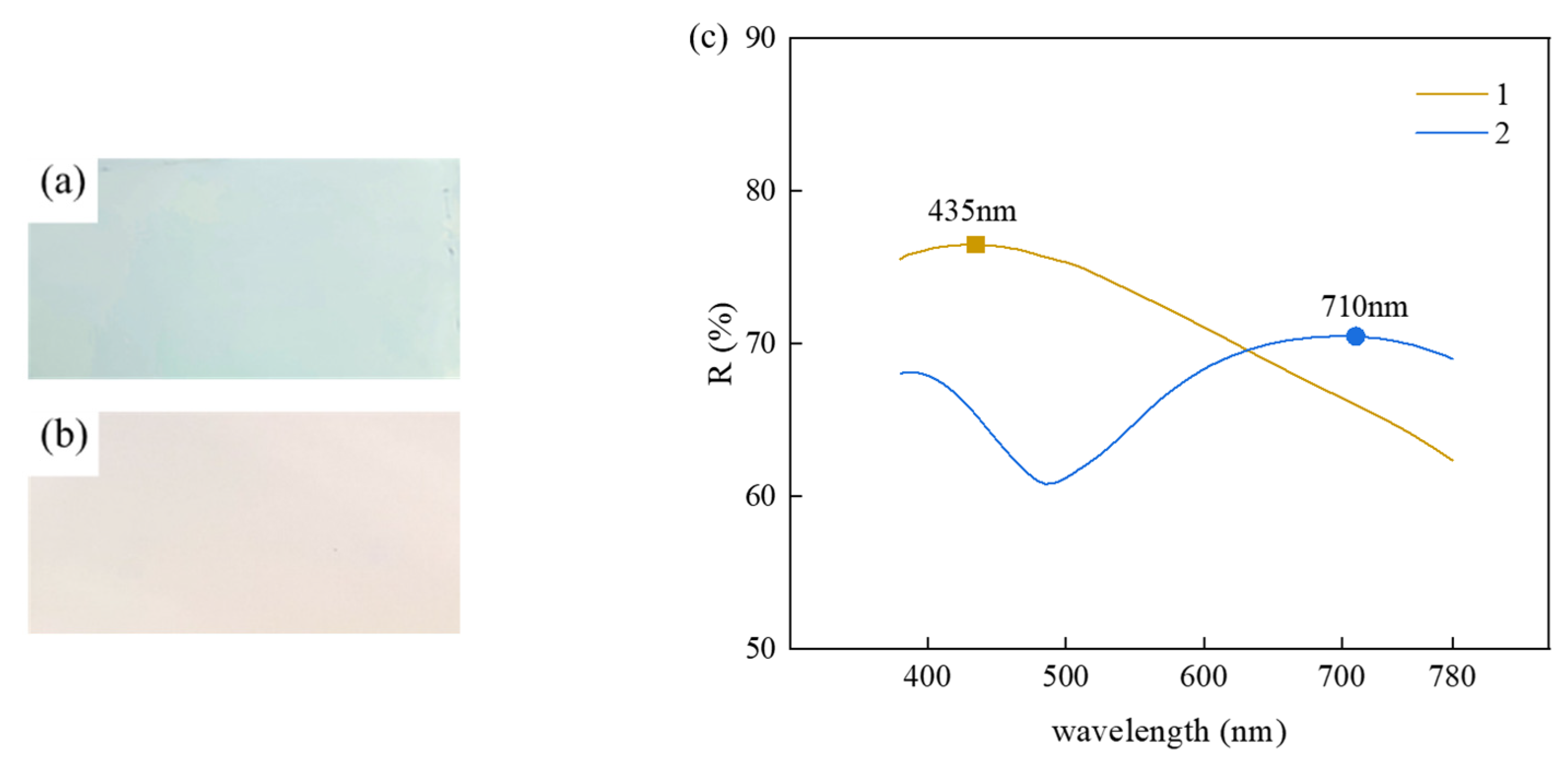
Figure 3 compares the cross-sectional SEM images of the two groups of samples. Distinct pore depth differences can be observed in the quasi-honeycomb structures, suggesting strong connection between visible color and pore depth. One possible reason is that when visible light irradiated the sample surface, Bragg diffraction occurred to the ordered AAO micro-honeycomb pore structures, reflecting a portion of the incident light before reaching the bottom. The remaining light transmitted through the AAO layer and was reflected by the aluminum substrate at the bottom, propagating back through the AAO layer to the surface. When light propagated in porous structures, it was possibly absorbed and scattered in a way by the AAO layer, leading to intensity attenuation. However, given that the AAO layers prepared in our experiments were all very thin, this attenuation should have been too modest to compromise the high reflectance of the aluminum substrate [28]. Hence, the ultimate visible colors of the samples resulted from the coupling of light interference and scattering in porous structures.

3.2. DC Ion Gold Sputtering

After treatment by two-step anodization, the aluminum foil displayed visually light coloration. In order to further enhance the characteristic colors and obtain high-saturation samples, we decided to deposit a layer of gold particles onto the AAO substrate by DC ion sputtering. Among samples treated under the two coating sequences, we marked the widening → coating series as K-Au and the coating → widening series as W-Au. Before sputtering treatment, the visible color of sample 1 was light blue. Table 3 gives the properties of sample 1 after sputtered with gold particles under different conditions. The gold-coated AAO samples showed remarkably improved saturation, and saturation enhanced with increasing coating duration.
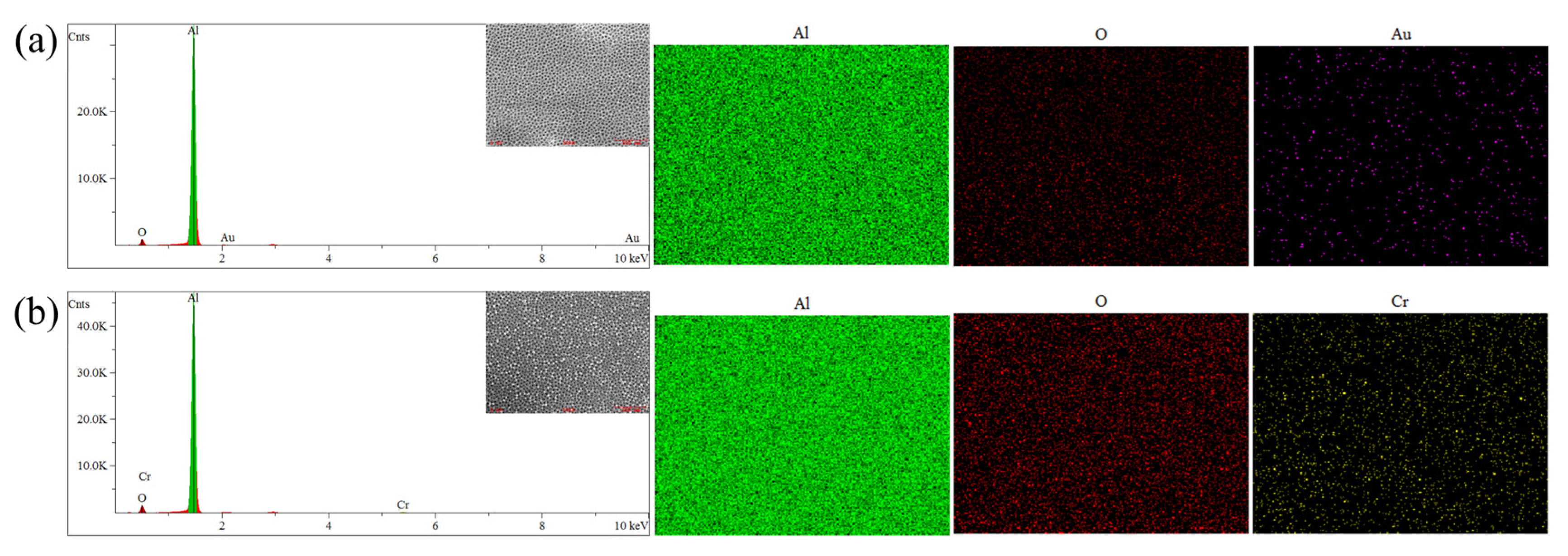
The gold-coated AAO samples displayed low reflectance in the 8–14 μm band. As shown in Table 3, all the gold-coated samples had an infrared emissivity (ε = 0.070–0.076) lower than the post-widening raw AAO materials (ε = 0.076), which disagrees with the intrinsic infrared irradiation behavior of metallic gold (theoretical emissivity ε < 0.05). Short-duration sputtering (<30 min) prevented the gold nanoparticles from forming a continuous, dense film. Some particles deposited at the bottom of the AAO pores while others spread as isolated islands on the surface. This non-continuous coating not only retained the low emissivity of metals but also enhanced visible color saturation via the interfacial interactions between nanoparticles and the AAO substrate.
This observation is intuitively supported by the SEM microstructural changes in Figure 4. As the coating duration increases from 10 s to 30 s, the SEM photo displays substantial expansion of bright surface regions (high-conductivity gold layers).
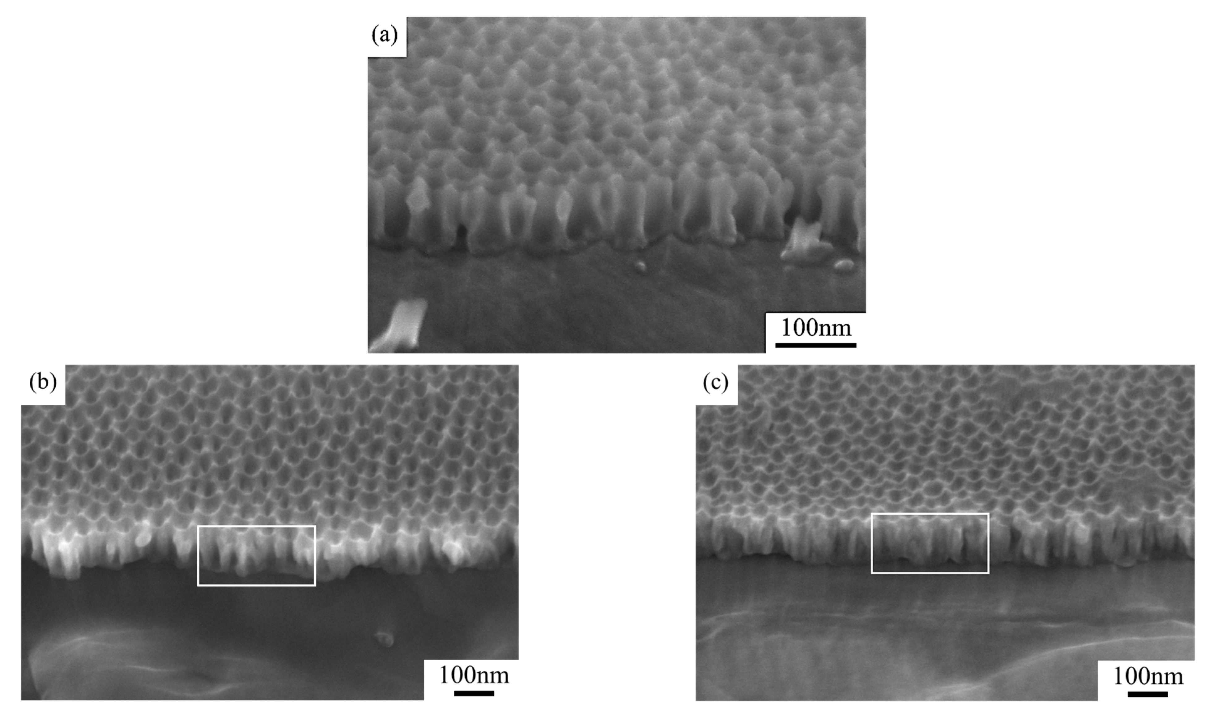
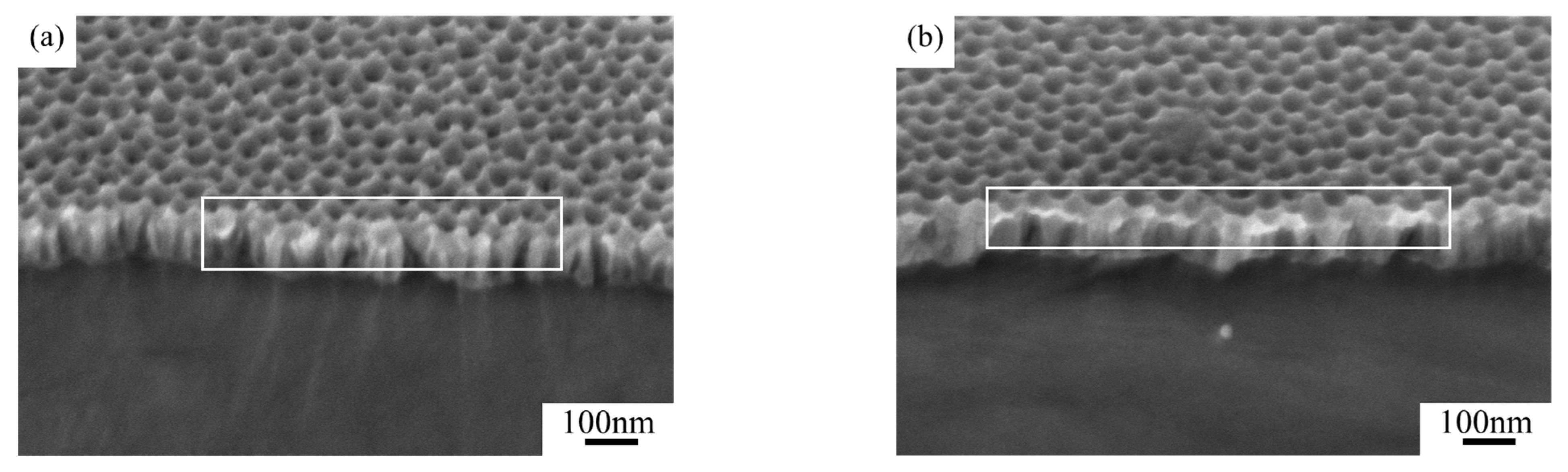
Further comparisons of the K-Au and W-Au processes revealed that coating sequence makes a great difference to AAO pore structures. From the cross-sectional SEM image of W-Au samples (Figure 5c), the original pores were severely clogged by gold particles, limiting subsequent phosphoric acid infiltration and diminishing structural coloration. Under the K-Au process, the pre-widened AAO template provided sufficient space for the deposition of gold particles, allowing for them to preferentially deposit on the aluminum/AAO interface. This treatment not only enhanced diffuse reflection at the aluminum substrate and improved color saturation but also further reduced infrared emissivity.
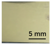
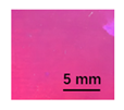
Similarly, we sputtered gold particles onto sample 2 under the same conditions. Before it was sputtered, sample 2 displayed light pink coloration. 
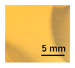
Table 4 gives the experimental result of sample 2 under different sputtering conditions. Coating treatment remarkably improved sample saturation, and saturation enhanced with increasing coating duration. Under both gold sputtering sequences, visible color evolved from yellow to pink. One possible reason is that in the initial stage (K21-Au/W21-Au), few gold particles deposited; the deposited particles were small-sized and sparsely distributed. Plasmonic effect emerged, leading to yellow coloration. With the increase in coating duration (K23-Au/W23-Au), more particles deposited; the deposited particles were larger-sized and more densely distributed. A redshift occurred to the surface plasmon resonance peak, leading to gradual pink coloration [29].
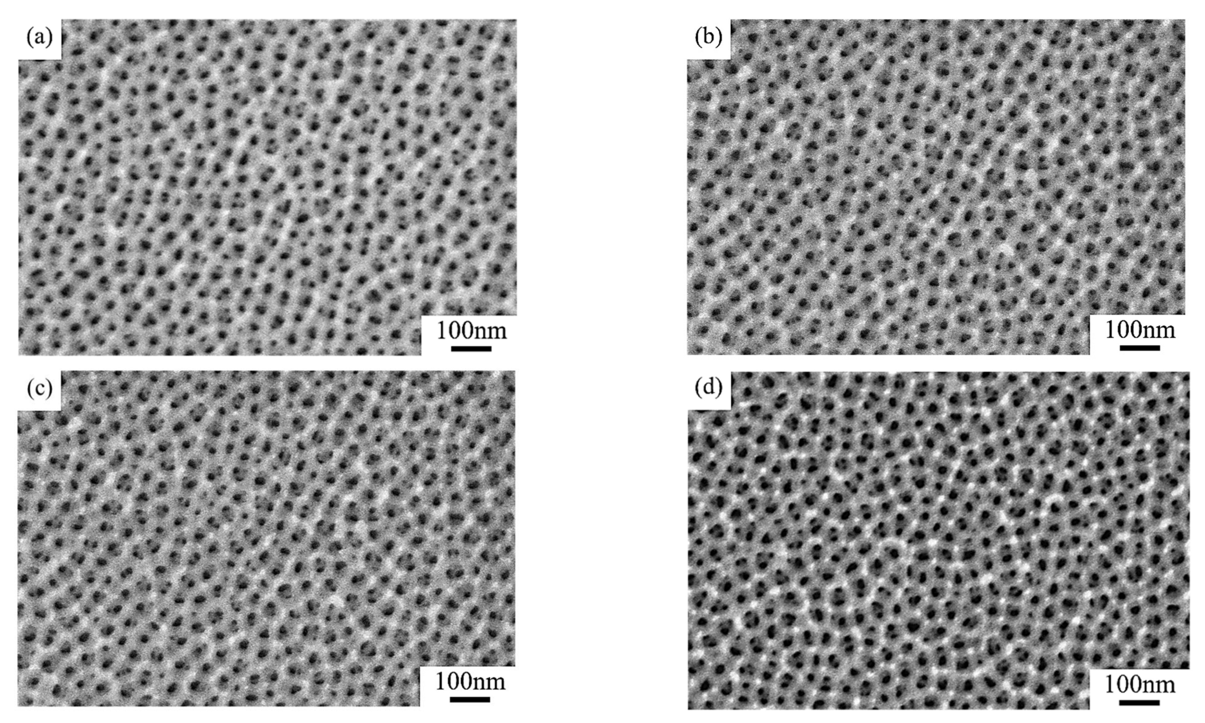
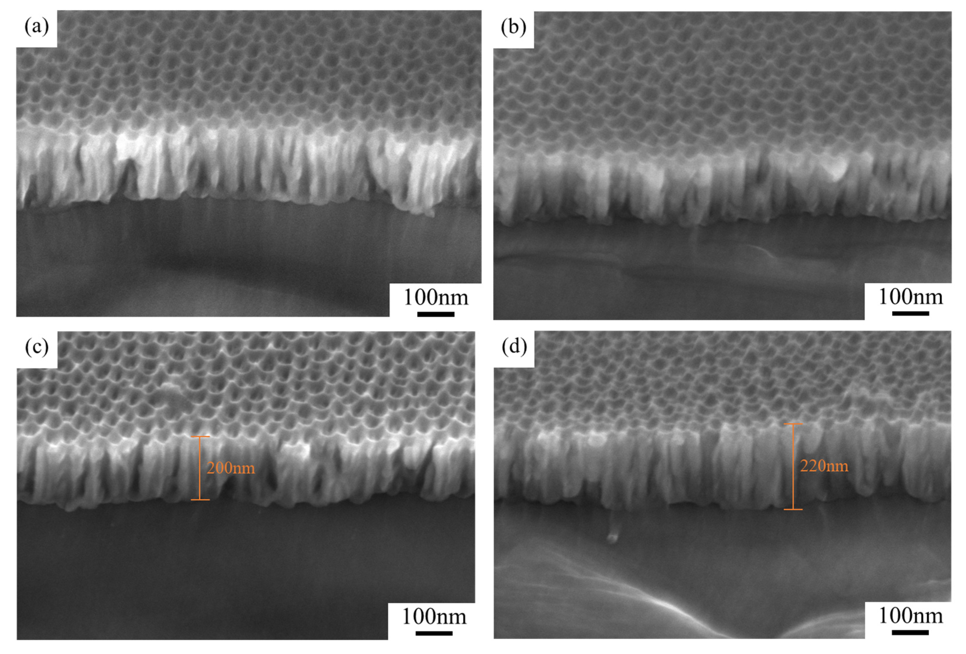
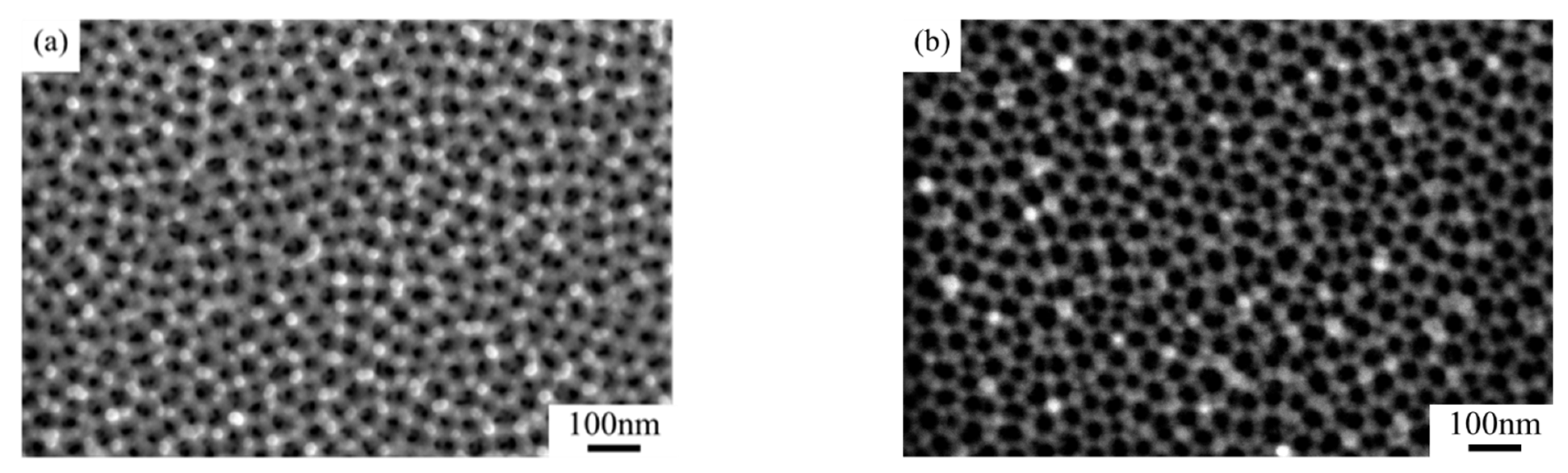
Figure 6a–d show the pore structures of AAO samples under different coating sequences. Comparisons of the microstructural evolution of the two groups of samples revealed that pore structures were unobvious in the W-Au group (Figure 6b,d), possibly because when the samples were coated before pore widening, phosphoric acid solution could hardly etch the pore walls and barrier layer at the bottom uniformly. Further investigation of the influence of coating duration on pores indicated that for both the K-Au and W-Au samples, as the coating duration increased from 10 s to 20 s, the pore size reduced non-uniformly; the pore depth increased from approximately 200 nm to approximately 220 nm. The cross-sectional pore profile changed from a flat-top to U-shape. Isolated nanoparticles (about 5 nm in diameter) produced by short-duration sputtering preferentially attached to pore rims.
Unlike sample 1, after coating treatment, sample 2 did not show higher color saturation in the K-Au group compared to the W-Au group, possibly because sample 2 had an average pore depth of 224.37 nm—which is far greater than sample 1 (110.17 nm). Under the same sputtering conditions, gold particles not only deposited on the AAO surface and the exposed aluminum substrate but also partially infilled the deeper pore walls. This changed the light reflection paths, leading to a reduction in color saturation.
In terms of infrared emissivity, the gold-coated AAO samples displayed distinct low reflectance in the 8–14 μm band. As shown in Table 4, all gold-coated samples had an infrared emissivity (ε = 0.101–0.113) lower than the post-widening raw AAO samples (ε = 0.115). The infrared emissivity of all prepared samples was smaller than 0.2 in the 8–14 μm band, demonstrating extraordinary infrared stealth performance.
Comparisons of experimental results indicated that DC ion gold sputtering greatly enhanced structural color saturation; proper thickness of gold coating also helped reduce infrared emissivity. Unfortunately, the high cost of gold targets and the limitation to small-area coating restrict the wide application of the DC sputtering process in stealth materials. Magnetron chromium sputtering, in contrast, is more suitable for large-area coating due to its high deposition rate and uniform coating. After optimizing process parameters, it can successfully modify the structural coloration of the prepared low-infrared-emissivity AAO materials.

3.3. UHV Vacuum Magnetron Chromium Sputtering

Similar to gold sputtering, we used two magnetron chromium sputtering sequences: widening → coating, marked as K-Cr, and coating → widening, marked as W-Cr. Table 5 gives the experimental result of samples under different chromium coating conditions. Coating treatment remarkably improved saturation, and saturation enhanced with increasing coating duration. The chromium-coated AAO samples still retained low emissivity in the 8–14 μm band. As shown in Table 5, all chromium-coated samples had a slightly higher infrared emissivity (ε = 0.077–0.107) compared to the post-widening raw AAO samples (ε = 0.076), but the overall increase was modest, suggesting that they still retained excellent infrared stealth performance.
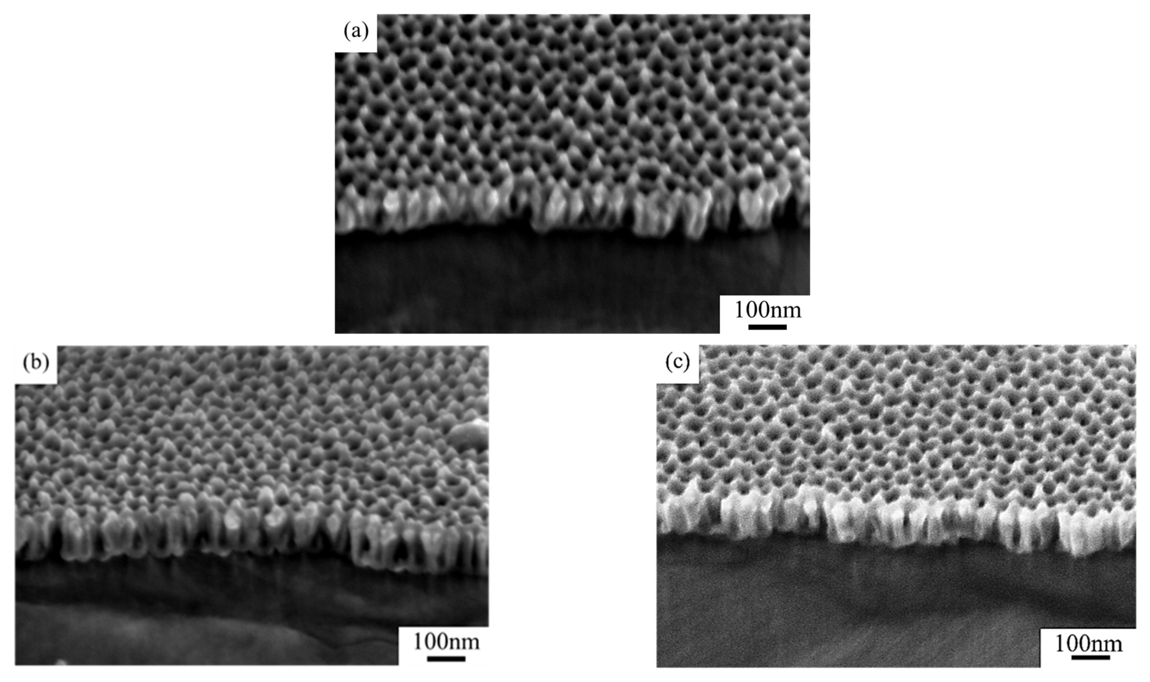
Figure 7 compares the cross-sectional microstructures of stealth materials under different coating durations. When the coating duration increased from 20 s to 60 s, the average thickness of the K-Cr group stayed at 70 nm, despite gradual narrowing of the nanopores. With the increase in coating duration, more chromium particles attached to the samples. As can be seen in Figure 7c, the chromium particles spread at the pore rims, evolving into a U-shaped profile.
Conductive metal chromium exhibited brighter color contrast under the electron beam of SEM imaging. Figure 8 compares the SEM surface microstructures of samples treated under different coating sequences. The W-Cr sample W12-Cr displayed smaller chromium coverage on the surface due to the lower power of magnetron chromium sputtering (30 W), thin coating layer, and poor Cr-AAO adhesion, which led to partial delamination of the chromium layer during subsequent pore widening. SEM characterization demonstrated alignment among samples in microstructural and infrared emissivity variations under different process conditions: as coating duration increased, some pores were clogged by chromium particles, slightly enhancing infrared emissivity. The W-Cr samples displayed slightly lower overall infrared emissivity compared to the K-Cr samples, as sputtering → widening compromised the continuity of the high-reflectivity chromium metal layer on the sample surface.
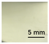
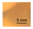
We sputtered chromium particles onto AAO sample 2 under the same conditions. The untreated raw sample displayed visible light pink coloration. Table 6 gives the experimental result under different chromium sputtering conditions. Similar to previous observations, coating treatment remarkably improved saturation, and saturation enhanced with coating duration. Overall, under both chromium coating sequences, visible color evolved from yellow to pink. One possible reason is that the non-continuous film layer formed on the AAO surface by chromium nanoparticles triggered localized surface plasmon resonance. Increased chromium particle size induced plasmon resonance redshift, intensifying blue light absorption and leading to a redshift from yellow to pink.
After magnetron chromium coating, the samples displayed identical microstructural changes as in previous experiments. With the increase in coating duration, more chromium particles deposited on the surface of the AAO samples. Some chromium particles deposited on the pore walls, narrowing pore diameter and reducing the exposed surface area of the aluminum substrate. These caused a slight increase in infrared emissivity. However, unlike previous observations, at chromium coating durations of 40 s and 60 s, the infrared emissivity of the W-Cr samples was 0.002 lower than in the K-Cr samples. This minor reduction in infrared emissivity is possibly attributed to the limited initial pore size of the W-Cr samples. Under longer coating durations, chromium primarily deposited on the AAO surface, forming a continuous chromium layer, as shown in Figure 9. This metal protective layer shielded the AAO layer during subsequent pore widening in phosphoric acid, leading to further infrared emissivity reduction, and consequently excellent infrared stealth performance, due to the coupling of the high reflectivity of metallic chromium and the low infrared emissivity of the raw AAO material. A continuous chromium layer also contributed to a slight pore depth increase in the porous layer, leading to a slight redshift in the sample’s visible coloration.

3.4. Low Color Difference Characterization of Visible Light

All samples prepared in our experiments displayed extraordinary infrared stealth performance, with <0.16 infrared emissivity and rich visible colors. Next, we compared the color differences of the prepared samples against PANTONE standard colors.
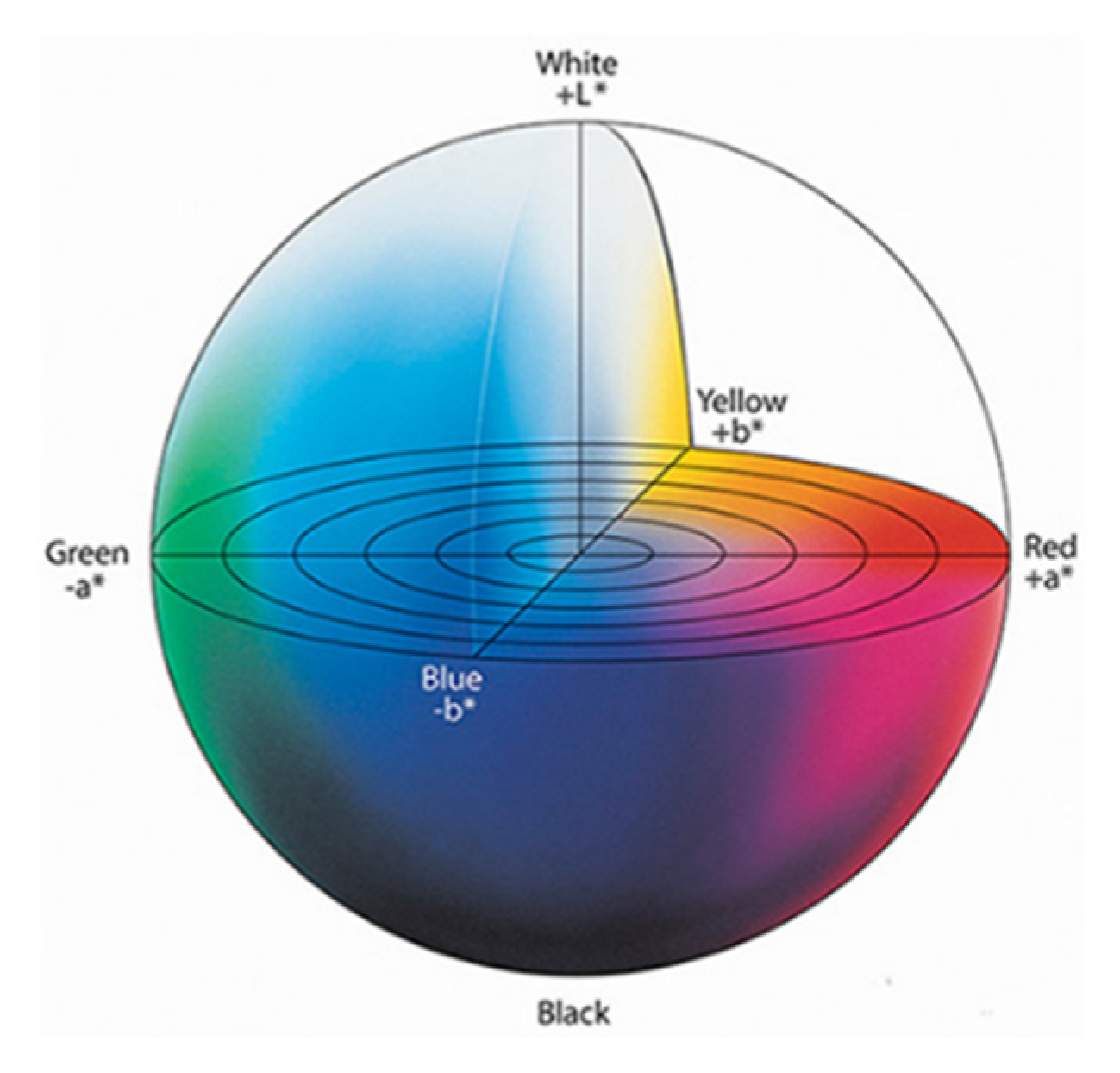
Color difference is calculated according to the CIE Lab uniform color space color difference formula, written as
Δ E a b * = ( Δ L * ) 2 + ( Δ a * ) 2 + ( Δ b * ) 2
where Δ E a b * is the CIE Lab uniform color space color difference; Δ L * , Δ a * , and Δ b * are the L*, a*, and b* differences between two colors, where L represents luminance, a represents red/green value, and b represents yellow/blue value. The color space is illustrated in Figure 10.
The stealth materials prepared in our experiments reflected light over the visible spectrum combining specular and diffuse reflection components. We measured the chromaticity of the samples using a visible spectrophotometer in conjunction with the standard specular component included (SCI) URA reflection module of a colorimeter. The material’s unique reflectivity causes discrepancies between instrumental testing and visual color assessments. Furthermore, the AAO’s porous nanostructure induces visible-light color variations with the incident light angle. For instance, slight sample surface irregularities can lead to minor differences between the measured color values and those from perpendicular incidence photography. In order to evaluate the samples’ coloration intuitively, we converted the measured Lab values of the samples into color swatches and tabulated them against PANTONE standard colors. The Pantone Matching System is a globally recognized industrial color standard. It offers thousands of precise, reproducible colors, including typical colors found in urban architecture, facilities, and industrial products. It provides a standardized and quantifiable reference library for defining “urban background colors”.
The sensitivity and tolerance levels of color difference vary across applications. Color difference is hardly perceived when Δ E a b * ≤ 1.0; within the range Δ E a b * = 1–3.0, color differences become perceptible but are still tolerable. In architectural applications, especially when viewing facade materials or concealed engineering systems (e.g., AAO stealth materials examined here) from long distances, slight color differences ( Δ E a b * = 1.5–2.0) are normally deemed to be functionally tolerable. From Table 7 and Table 8, all gold-coated samples matched with PANTONE standard colors, with Δ E a b * values between 0.2 and 1.6. Obviously, our stealth material had minimal color difference from standard colors, demonstrating excellent camouflage performance.
According to the colorimetric measurements of the gold-coated samples in Table 9 and the chromium-coated samples in Table 10, compared to the gold-coated samples, the chromium-coated samples had a higher overall color saturation but a lower matching accuracy with PANTONE standard colors ( Δ E a b * = 1.4–3.0, which is still within human-perceptible tolerance limits). Comparisons between raw sample photos and the measured Lab-converted swatches also indicated that, due to limitations of instrumental measurement, the measured Lab values of some samples failed to reflect the accurate raw sample coloration. As the chromium-coated samples have stronger specular reflection, this could also contribute to color difference deviations.
By preparing and characterization these samples, we found that both DC ion gold sputtering and UHV magnetron chromium sputtering significantly enhanced structural color saturation. The optimized materials could retain extraordinary infrared stealth performance (emissivity ε < 0.161) while keeping visible color difference Δ E a b * below 3.0 (CIE Lab standard color system). The gold-coated samples had smaller color differences from standard colors. The chromium-coated ones had lower matching accuracy with PANTONE standard colors but higher saturation and brightness, displaying a distinct coloration compared to the gold-coated samples but aligning better with the coloration of glass curtain walls in urban contexts.
In this study, all prepared materials exhibit an average infrared emissivity below 0.2 within the 8–14 μm wavelength range, demonstrating effective infrared stealth performance. While color differences relative to standard colors vary among samples, color volume coverage was calculated for materials with Δ E a b * ≤ 2.0 using the formula
Color Volume Coverage = ΔL × Δa × Δb
where ΔL, Δa, and Δb represent the differences between maximum and minimum CIE Lab values. The calculation yields
Color Volume Coverage = (87.58 − 53.36) × [27.08 − (−3.77)] × [32.16 − (−36.37)] ≈ 72,506.5
The Color Coverage Ratio, defined as the proportion of color volume coverage to the total CIE Lab color space volume, is calculated as
(72,506.5/1,436,214) × 100% ≈ 5.05%
This indicates a relatively broad color distribution among these materials within the CIE Lab color space, suggesting rich color diversity. A color coverage rate of 5.05% implies these materials exhibit certain representativeness in the color space, with colors predominantly concentrated in blue tones, red tones, and high-luminance regions.
These comprehensive measurements and comparisons enabled us to ensure that the prepared materials are color-compatible with urban architectural environments, achieving better camouflage performance in real-world applications. In our experiments, two coating methods, DC ion sputtering of gold and magnetron sputtering of chromium, are used, both of which can effectively enhance the color saturation of AAO materials. Meanwhile, by adjusting the coating parameters, multicolor materials with subtle color differences can be prepared. Based on these experimental results, if we want to further broaden the color range of AAO stealth materials, we can first obtain the base materials with different structural colors by regulating the anodic oxidation conditions when preparing AAO materials and then use the above coating methods to enhance their saturation [8].

3.5. Compositional Characterization

EDS surface elemental mapping (Figure 11) confirmed the presence of trace metallic Au/Cr coatings on the low-color-difference samples W12-Au and K11-Cr after coating. XRD analysis of the stealth materials (Figure 12) revealed distinct crystalline features. Figure 12a shows narrow, high-intensity diffraction peaks characteristic of face-centered cubic (FCC) aluminum, indicating dominant contributions from the aluminum substrate. The thinness of both the anodized alumina porous layer and sputtered metal layer resulted in minimal interference with the substrate’s diffraction patterns. After substrate removal, the alumina film’s XRD spectrum (Figure 12b) exhibited a broad amorphous hump without sharp crystalline peaks. Collectively, these results demonstrate that the low-color-difference stealth material comprises three primary components: an aluminum substrate, an amorphous Al2O3 layer, and a thin sputtered metallic (Au/Cr) coating.

4. Conclusions

We explored AAO materials combining low infrared emissivity and visible structural coloration through multi-parameter modulation. After coating AAO samples by DC ion gold sputtering and UHV magnetron chromium sputtering, we systematically characterized the microstructures and infrared signatures of the samples in the 8–14 μm band across different process parameters (coating duration, coating sequence) and quantified their matching accuracy with PANTONE standard colors based on CIE Lab color difference model. Both processes optimized visible structural coloration. As the sputtered film can form a partially continuous metallic layer over the AAO surface, extraordinary infrared stealth performance was retained (emissivity ε < 0.161). Under all coating sequences and durations, the prepared samples displayed broad-spectrum visible coloration (cold/warm tones, low/high saturation). The gold-coated samples had high matching accuracy with PANTONE standard colors ( Δ E a b * < 1.6). The chromium-coated ones deviated from standard color gamuts ( Δ E a b * < 3.0) due to higher saturation, colder tones, and higher reflectivity, but they still displayed rich visible coloration, with color difference within human-perceptible tolerance limits. Our findings offer new ideas and approaches for designing visible–infrared-compatible stealth materials in urban environments.

Author Contributions

Conceptualization and Methodology, X.R.; Validation, D.W.; Investigation and Resources, H.L.; Data Curation and Writing—Original Draft Preparation, Y.W. (Yichen Wang); Writing—Review and Editing, Y.W. (Yichen Wang) and Y.W. (Yu Wu); Project Administration, Y.W. (Yu Wu). All authors have read and agreed to the published version of the manuscript.

Funding

This research received no external funding.

Data Availability Statement

Data are contained within the article.

Conflicts of Interest

The authors declare no conflicts of interest.

References

  1. ISO/CIE 11664-6:2014; Colorimetry—Part 6: CIEDE2000 Colour-Difference Formula. International Organization for Standardization/Commission Internationale de l’Éclairage: Geneva, Switzerland, 2014.
  2. Fu, Z.; Jia, S.; Wang, F.; Yan, H.; Cheng, Z. Multispectral stealth structures for simultaneous visible-infrared stealth and efficient heat dissipation. J. Quant. Spectrosc. Radiat. Transf. 2025, 337, 109397. [Google Scholar] [CrossRef]
  3. Guan, C.; Su, S.; Wang, B.; Zhong, J.; Chen, J.; Sun, F.; Zhan, L. Electromagnetic stealth technology: A review of wave-absorbing structures. Mater. Des. 2025, 253, 113891. [Google Scholar] [CrossRef]
  4. Pan, Y.; Huang, L.; Sun, W.; Gao, D.; Li, L. Invisibility Cloak Technology of Anti-Infrared Detection Materials Prepared Using CoGaZnSe Multilayer Nanofilms. ACS Appl. Mater. Interfaces 2021, 13, 40145–40154. [Google Scholar] [CrossRef] [PubMed]
  5. Domagalski, J.T.; Xifre-Perez, E.; Marsal, L.F. Recent Advances in Nanoporous Anodic Alumina: Principles, Engineering, and Applications. Nanomaterials 2021, 11, 430. [Google Scholar] [CrossRef]
  6. Kondo, T.; Miyazaki, H.; Yanagishita, T.; Masuda, H. Anodic porous alumina with elliptical apertures. Electrochem. Commun. 2018, 96, 61–65. [Google Scholar] [CrossRef]
  7. Gunenthiran, S.; Wang, J.; Law, C.S.; Abell, A.D.; Alwahabi, Z.T.; Santos, A. Nanoporous anodic alumina photonic crystals for solid-state lasing systems: State-of-the-art and perspectives. J. Mater. Chem. C 2025, 13, 985–1012. [Google Scholar] [CrossRef]
  8. Wang, Y.; Jin, Q.; Liu, H.; Ren, X.; Wu, Y. Fabrication and performance of visible-infrared stealth material imitating butterfly wings. Ceram. Int. 2025. [Google Scholar] [CrossRef]
  9. Arango, F.; Sepúlveda, M.; Aguilar-Sierra, S.; Ricaurte, G.; Echeverría, F. Interferometric colours produced by anodised aluminium diffraction grating. Mater. Sci. Technol. 2020, 36, 1238–1244. [Google Scholar] [CrossRef]
  10. Nazemi, A.; Najafian, A.; Sadjadi, S.A.S. Aluminium oxide nanowires synthesis from high purity aluminium films via two-step anodization. Superlattices Microstruct. 2015, 81, 1–6. [Google Scholar] [CrossRef]
  11. Xu, Q.; Xue, Y.; Miao, M.; Shi, X. Au nanostructures with controllable morphology in porous anodic aluminum oxide templates. Chem. Phys. 2024, 580, 112241. [Google Scholar] [CrossRef]
  12. Afsin, P.; Akyil, C.; Kazmanlı, K.; Ürgen, M. Electro-Coloring Mechanism of Aluminum Anodic Oxides in Tin-Based Electrolytes. Coatings 2024, 14, 616. [Google Scholar] [CrossRef]
  13. Abedini, M.; Hanke, S. Improving the wear resistance of aluminum by a nickel-filled anodized porous alumina layer. Wear 2023, 522, 204858. [Google Scholar] [CrossRef]
  14. Liu, H.; Pan, Z.-Z.; Itoh, T.; Kyotani, T.; Nishihara, H. Carbon-coated anodic aluminum oxide: Synthesis, characterization, and applications. Appl. Phys. Rev. 2024, 11, 031313. [Google Scholar] [CrossRef]
  15. Kumar, R.; Dixit, A. Corrosion resists Ni, Co co-pigmented nanoporous anodized alumina as spectral selective coating structure for solar thermal applications. J. Alloy. Compd. 2019, 810, 151833. [Google Scholar] [CrossRef]
  16. Wang, H.; Wei, M.; Zhong, Z.; Wang, Y. Atomic-layer-deposition-enabled thin-film composite membranes of polyimide supported on nanoporous anodized alumina. J. Membr. Sci. 2017, 535, 56–62. [Google Scholar] [CrossRef]
  17. Zhu, L.; Yang, G.L.; Ding, W.J.; Cao, Y.Q.; Li, W.M.; Li, A.D. Growth behavior of Ir metal formed by atomic layer deposition in the nanopores of anodic aluminum oxide. Dalton Trans. 2022, 51, 9664–9672. [Google Scholar] [CrossRef]
  18. Chung, C.; Li, C.; Hsieh, Y.; Wang, Z. Microstructure and photoluminescence of sputtered silicon-rich-nitride on anodic aluminum oxide annealed at low temperature. J. Alloy. Compd. 2017, 709, 658–662. [Google Scholar] [CrossRef]
  19. Mozalev, A.; Bendova, M.; Gispert-Guirado, F.; Llobet, E.; Habazaki, H. Porous-anodic-alumina-templated Ta-Nb-alloy/oxide coatings via the mag-netron-sputtering/anodizing as novel 3D nanostructured electrodes for energy-storage applications. Surf. Coat. Technol. 2024, 489, 131042. [Google Scholar] [CrossRef]
  20. Lee, K.; Kim, H.; Kim, J.H.; Choi, D. Structural color and near-infrared tunability of ruthenium-coated anodic aluminum oxide by atomic layer deposition. Scr. Mater. 2020, 187, 125–129. [Google Scholar] [CrossRef]
  21. Xu, Q.; Lan, T.; Wang, Z.; Sun, C.; Peng, Q.; Sun, H. Preparation and growth mechanism of a gold-coloured Ag@AAO composite film with no angular dependence. Appl. Surf. Sci. 2021, 553, 149592. [Google Scholar] [CrossRef]
  22. Pashchanka, M.; Yadav, S.; Cottre, T.; Schneider, J.J. Porous alumina-metallic Pt/Pd, Cr or Al layered nanocoatings with fully controlled variable interference colors. Nanoscale 2014, 6, 12877–12883. [Google Scholar] [CrossRef] [PubMed]
  23. Fang, S.; Xu, N.; Zhou, L.; Wei, T.; Yang, Y.; Liu, Y.; Zhu, J. Self-assembled skin-like metamaterials for dual-band camouflage. Sci. Adv. 2024, 10, eadl1896. [Google Scholar] [CrossRef]
  24. Zhang, S.Y.; Xu, Q.; Wang, Z.J.; Hao, S.Z.; Sun, C.X.; Ma, W.J. Preparation and characterization of anodic alumina films with high-saturation structural colors in a mixed organic electrolyte. Surf. Coat. Technol. 2018, 346, 48–52. [Google Scholar] [CrossRef]
  25. Li, M.; Feng, C.; Zhu, L.; Zhao, Y. Fabrication of nanoporous anodized aluminum oxide based photonic crystals with multi-band responses in the vis-NIR region. Nanoscale 2025, 17, 4099–4110. [Google Scholar] [CrossRef] [PubMed]
  26. Cantons, J.M.; Acosta, L.K.; Formentin, P.; Ferré-Borrull, J.; Bachhuka, A.; Marsal, L.F. Real-Time Detection of Human Growth Hormone Based on Nanoporous Anodic Alumina Interferometric Biosensor. Sensors 2025, 25, 1021. [Google Scholar] [CrossRef] [PubMed]
  27. Pligovka, A.; Lazavenka, A.; Turavets, U.; Hoha, A.; Salerno, M. Two-Level 3D Column-like Nanofilms with Hexagonally–Packed Tantalum Fabricated via Anodizing of Al/Nb and Al/Ta Layers—A Potential Nano-Optical Biosensor. Materials 2023, 16, 993. [Google Scholar] [CrossRef]
  28. Kushnir, S.E.; Napolskii, K.S. Thickness-dependent iridescence of one-dimensional photonic crystals based on anodic alumina. Mater. Des. 2018, 144, 140–150. [Google Scholar] [CrossRef]
  29. Rattanawongwiboon, T.; Soontaranon, S.; Hemvichian, K.; Lertsarawut, P.; Laksee, S.; Picha, R. Study on particle size and size distribution of gold nanoparticles by TEM and SAXS. Radiat. Phys. Chem. 2022, 191, 109842. [Google Scholar] [CrossRef]
Figure 1. Infrared emissivity spectra of the raw AAO samples.
Nanomaterials 15 00890 g001
Figure 2. Visible light photos of (a) AAO sample 1 and (b) sample 2 and (c) visible spectra.
Nanomaterials 15 00890 g002
Figure 3. Post-widening cross-sectional SEM photos of (a) sample 1 and (b) sample 2.
Nanomaterials 15 00890 g003
Figure 4. Surface SEM photos of (a) raw sample 1, (b) K11-Au, (c) K12-Au, and (d) K13-Au.
Nanomaterials 15 00890 g004
Figure 5. Cross-sectional SEM photos of (a) raw sample 1, (b) K12-Au, and (c) W12-Au.
Nanomaterials 15 00890 g005
Figure 6. Cross-sectional SEM photos of samples (a) K21-Au, (b) W21-Au, (c) K22-Au, and (d) W22-Au.
Nanomaterials 15 00890 g006
Figure 7. Cross-sectional SEM photos of samples (a) K11-Cr, (b) K12-Cr, and (c) K13-Cr.
Nanomaterials 15 00890 g007
Figure 8. Surface SEM photos of samples (a) K12-Cr and (b) W12-Cr.
Nanomaterials 15 00890 g008
Figure 9. Cross-sectional SEM photos of samples (a) K23-Cr and (b) W23-Cr.
Nanomaterials 15 00890 g009
Figure 10. Color space diagram.
Nanomaterials 15 00890 g010
Figure 11. EDS surface elemental mapping results for (a) W12-Au and (b) K11-Cr samples.
Nanomaterials 15 00890 g011
Figure 12. XRD analysis of (a) stealth material and (b) interlayer material.
Nanomaterials 15 00890 g012
Table 1. Process parameters for two-step anodization.
Primary AnodizationRemove Oxide FilmSecondary Anodization
T1/°CU1/Vt1/minT2/°CU2/Vt2/min
1152045Immersed in mixed acid solution at 70 °C for 20 min5205
215204552010
Table 2. Preparation parameters for different sample numbers.
Conditional
t2/min510
Sample No.K11K12K13W11W12W13K21K22K23W21W22W23
Coating typeAu
Coating duration102030102030102030102030
Coating typeCr
Coating duration204060204060204060204060
Table 3. Experimental result of AAO sample 1 under different gold sputtering conditions.
Au Sputtering Duration/sSample No.Optical PhotoIR EmissivitySample No.Optical PhotoIR Emissivity
10 sK11-AuNanomaterials 15 00890 i0010.070W11-AuNanomaterials 15 00890 i0020.073
20 sK12-AuNanomaterials 15 00890 i0030.070W12-AuNanomaterials 15 00890 i0040.074
30 sK13-AuNanomaterials 15 00890 i0050.071W13-AuNanomaterials 15 00890 i0060.076
Table 4. Experimental result of AAO sample 2 under different gold sputtering conditions.
Au Sputtering Duration/sSample No.Optical PhotoIR EmissivitySample No.Optical PhotoIR Emissivity
10 sK21-AuNanomaterials 15 00890 i0070.101W21-AuNanomaterials 15 00890 i0080.103
20 sK22-AuNanomaterials 15 00890 i0090.107W22-AuNanomaterials 15 00890 i0100.108
30 sK23-AuNanomaterials 15 00890 i0110.110W23-AuNanomaterials 15 00890 i0120.113
Table 5. Experimental result of AAO sample 1 under different chromium coating conditions.
Cr Coating Duration/sSample No.Optical PhotoIR EmissivitySample No.Optical PhotoIR Emissivity
20 sK11-CrNanomaterials 15 00890 i0130.077W11-CrNanomaterials 15 00890 i0140.081
40 sK12-CrNanomaterials 15 00890 i0150.079W12-CrNanomaterials 15 00890 i0160.087
60 sK13-CrNanomaterials 15 00890 i0170.086W13-CrNanomaterials 15 00890 i0180.107
Table 6. Experimental result of AAO sample 2 under different chromium coating conditions.
Cr Coating Duration/sSample No.Optical PhotoIR EmissivitySample No.Optical PhotoIR Emissivity
20 sK21-CrNanomaterials 15 00890 i0190.114W21-CrNanomaterials 15 00890 i0200.124
40 sK22-CrNanomaterials 15 00890 i0210.136W23-CrNanomaterials 15 00890 i0220.134
60 sK23-CrNanomaterials 15 00890 i0230.161W23-CrNanomaterials 15 00890 i0240.159
Table 7. Colorimetric measurement result of gold-coated AAO sample 1.
Sample No.Measured Lab Value-Converted SwatchSaturation/CabPANTONE Standard Color Δ E a b *
K11-AuNanomaterials 15 00890 i0254.65Nanomaterials 15 00890 i0261.1
K12-AuNanomaterials 15 00890 i0276.52Nanomaterials 15 00890 i0281.1
K13-AuNanomaterials 15 00890 i02913.38Nanomaterials 15 00890 i0302.0
W11-AuNanomaterials 15 00890 i0315.01Nanomaterials 15 00890 i0320.6
W12-AuNanomaterials 15 00890 i0339.05Nanomaterials 15 00890 i0340.2
W13-AuNanomaterials 15 00890 i03510.85Nanomaterials 15 00890 i0360.8
Table 8. Colorimetric measurement result of gold-coated AAO sample 2.
Sample No.Measured Lab Value-Converted SwatchSaturation/CabPANTONE Standard Color Δ E a b *
K21-AuNanomaterials 15 00890 i03711.08Nanomaterials 15 00890 i0380.7
K22-AuNanomaterials 15 00890 i03917.34Nanomaterials 15 00890 i0401.6
K23-AuNanomaterials 15 00890 i04115.53Nanomaterials 15 00890 i0420.9
W21-AuNanomaterials 15 00890 i0439.57Nanomaterials 15 00890 i0440.6
W22-AuNanomaterials 15 00890 i04513.71Nanomaterials 15 00890 i0460.8
W23-AuNanomaterials 15 00890 i04727.83Nanomaterials 15 00890 i0481.1
Table 9. Colorimetric measurement result of chromium-coated AAO sample 1.
Sample No.Measured Lab Value-Converted SwatchSaturation/CabPANTONE Standard Color Δ E a b *
K11-CrNanomaterials 15 00890 i04928.15Nanomaterials 15 00890 i0501.4
K12-CrNanomaterials 15 00890 i05136.43Nanomaterials 15 00890 i0521.8
K13-CrNanomaterials 15 00890 i05339.73Nanomaterials 15 00890 i0542.5
W11-CrNanomaterials 15 00890 i05523.56Nanomaterials 15 00890 i0561.6
W12-CrNanomaterials 15 00890 i05736.8Nanomaterials 15 00890 i0582.3
W13-CrNanomaterials 15 00890 i05936.82Nanomaterials 15 00890 i0602.4
Table 10. Colorimetric measurement result of chromium-coated sample 2.
Sample No.Measured Lab Value-Converted SwatchSaturation/CabPANTONE Standard Color Δ E a b *
K21-CrNanomaterials 15 00890 i06146.83Nanomaterials 15 00890 i0622.0
K22-CrNanomaterials 15 00890 i06374.43Nanomaterials 15 00890 i0643.0
K23-CrNanomaterials 15 00890 i06548.79Nanomaterials 15 00890 i0662.4
W21-CrNanomaterials 15 00890 i06737.28Nanomaterials 15 00890 i0681.7
W22-CrNanomaterials 15 00890 i06950.17Nanomaterials 15 00890 i0702.0
W23-CrNanomaterials 15 00890 i07160.26Nanomaterials 15 00890 i0722.5
Disclaimer/Publisher’s Note: The statements, opinions and data contained in all publications are solely those of the individual author(s) and contributor(s) and not of MDPI and/or the editor(s). MDPI and/or the editor(s) disclaim responsibility for any injury to people or property resulting from any ideas, methods, instructions or products referred to in the content.

