1. Introduction
The offshore wind sector can now be considered to be in a commercial stage of development [
1]. According to a WindEurope report [
2], in Europe during 2017, the total output of offshore wind turbines constructed during the year totaled 3148 megawatts (MW), which is the annual installed power record since the creation of this technology (in 2015, the annual installed capacity was very close to that of 2017, but the rest of the years do not exceed half of the installed capacity in 2017). At the end of 2017, there was a total of 15,780 MW of generation in Europe (double that at the end of 2014), installed in 92 offshore wind farms, located in 11 countries across Europe [
2].
The total amount of installed power generation has been growing over time due to several factors, for instance: The installation of higher power wind turbines, larger numbers of wind turbines in each facility, the state of development of the offshore wind industry in different countries, the successes achieved in the sector, etc. This was accomplished by, among other reasons, moving to locations with greater depth, investigating new concepts for foundations and substructures, working to solve uncertainties in foundation design, implementing scour protection systems, and increasing the amount of investment to connect wind farms to energy grids [
3,
4].
The foundation is the key component in an offshore wind facility, representing the way through which the loads of the superstructure, in this case the wind turbine, are transmitted to the soil. Therefore, soil properties are essential in the selection of the type of foundation used in these facilities [
5].
Different types of foundation have been developed for use in the offshore wind industry. The most common types are steel monopiles, gravity-based structures (GBS), tripods, and jackets [
6]. Other types of foundations, such as suction caisson, concrete monopile, floating support, etc., are currently in a less advanced phase of development. This article focuses on GBS, also known as GBF (gravity-based foundations), being the type of foundation that is suitable in cases of soils with high bearing capacity. This is because of the way gravity structures support loads and transmit them to the soil [
7,
8].
Soils with a high load-bearing capacity allow the installation of shallow foundations [
9], such as the GBS. On the other hand, in the case of low load-bearing capacity soils, the best solution is to use deep foundations or propose soil improvement techniques, such as piles, either as a monopile or as a foundation for jackets or tripods. Other key aspects when deciding on the type of foundation to use are the depth of the water, the loads associated with the characteristics of the wind turbine, and the climatic loads (wind, waves, marine currents, tidal range) means of manufacturing, installation, operation, dismantling, etc. In fact, there are many considerations to be measured when selecting the most appropriate foundation for a wind turbine facility. The cost of the foundation is around 35% of the overall cost of the project. This significant cost is an important factor when both designing and choosing the foundation to be used.
Most types of foundation used in offshore wind, both direct to the ground and floating supports, are concepts inherited from the offshore oil and gas industries [
10,
11]. In particular, it is clear that GBS foundation originated from the oil and gas industries, with a structure known as a Condeep (concrete deep-water structure) [
12]. These are used for different water depths, with the maximum depth being 330 m (Troll Condeep, in the Norwegian sector of the North Sea, 1995). The first Condeep structure ever built was Ekofist I, in 1973, in the North Sea [
13,
14]. A Condeep is usually constructed in a fjord, given its good characteristics in terms of construction associated with sheltered waters and high-water depths [
15].
On the other hand, concrete structures are also used at sea in breakwaters and quay walls [
16], where many structures use the floating caisson technique [
17]. In fact, some companies have tried to use a similar concept for offshore wind farms. It is important to understand the differences that exist between offshore wind structures and breakwaters. The function of offshore wind foundations is to support the wind turbine, and the function of the breakwater is to shelter the interior area, so that ships can securely carry out loading and unloading operations. It is for this reason that the breakwaters have to stop a large amount of wave energy. Furthermore, in the case of the supporting structures of the wind turbines, it is important that the wave loads be as low as possible and as transparent as possible to waves, with the objective of reducing the cost of the structure.
According to WindEurope's report, at the end of 2017, monopile foundation in Europe was at the top of the classification, with 3720 units (81.7%), followed by the jacket, with 315 units, and the gravity based foundation, with 283 units. There were only seven floating platforms constructed during this period, six of which were SPARs and one which was semi-submersible.
According to those statistics, there are some offshore wind facilities operating in Europe that have GBS-type foundations; however, the small percentage of such cases indicates that GBFs have not been widely used in the industry up until now. This is due to the ease of use of monopiles, which represent >80% of offshore wind foundations. This characteristic of monopiles, together with their reduced cost, has displaced other types of foundations from a strategic position in the sector. However, as water depth increases, some limitations appear around the use of monopiles, potentially causing other types of foundations to increase in use.
Alternatives to the monopile have to be considered in locations with a terrain where the driving-in of monopiles is difficult, for instance, rocky soils. In such cases, the GBS is expected to work well. The main advantages of the GBS are: The good behavior of similar structures in the oil and gas and port engineering industries; its suitability as a foundation in rocky or sandy soils, with its high bearing capacity, where pile driving can be complicated; and it being an alternative that can enrich market competitiveness and therefore reduce of costs in any industry. The main disadvantages of the GBS are: It has not had great acceptance in the wind industry up to now; it needs soil with specific geotechnical properties, such as high bearing capacity; in general, previous soil preparation is needed for correct support of the structure; the large occupation area in the seabed, with its associated environmental impact; and the necessary means of manufacture, transport, and installation.
Although this typology has not previously been widely used, there are certain opinions that have highlighted its advantages over other types of foundations for both shallow and deep water sites. In fact, the offshore wind industry is trying to introduce improvements to turn it into a competitive foundation alternative in the widest range of water depths. There has been recent open discussion in some of the most important conferences on offshore wind energy about possible competition between jacket, XXL monopile, and GBS foundation types in water depths of around 40 m.
The importance of the GBS foundation for the future of the offshore wind industry is not currently discussed. As a consequence, this article is about GBS foundations, since it is fundamental to achieve greater knowledge about this concept. The paper provides a review of the different existing GBS foundation concepts. For this, on one hand, the foundations of wind farms in Europe that are already in operation are analyzed, and on the other, the main existing concepts that are in a less mature development phase, either at the research or prototype level, are identified. In addition, this article includes a classification of GBS foundations, elaborated on by the authors, based on offshore wind farms examples in operation. The paper also includes some reflections on the future of GBS alternatives.
2. Objectives and Research Methodology
The main aim of this paper is to show the different existing alternatives of GBS foundations for offshore wind facilities, including the already constructed ones and others in an early stage of development.
For that, it was necessary to find all the offshore wind farms in operation that have GBS foundations, and to study each specific design. After that, the different GBS foundation concepts were identified and classified. Then, GBS alternatives in an early phase of study were analyzed. For all of this, an in-depth literature review was carried out.
Based on available information, a classification proposal for the already constructed GBS foundations is elaborated on by the authors, in order to clarify the different existing general concepts in operating wind farms. Furthermore, some reflections are given on other GBS concepts that have not yet been proven, as well as an analysis on the future on this type of concept.
3. State of the Art and Discussion
This section includes two parts. The first (3.1) identifies the different offshore wind farms in operation in Europe that have GBS foundations. The second (3.2) concerns the different concepts of GBS foundations. This second part includes not only the collected state of the art, but also a discussion on this information.
3.1. European Offshore Wind Farms with GBS Foundations
European offshore wind farms with GBS foundations were identified, even those already dismantled (
Table 1); these were mainly culled from different reliable Internet sources [
18,
19].
In analyzing
Table 1, several conclusions can be drawn:
Total wind farms: 12, one dismantled. Seven are in Denmark, which is the current leader in the use of GBS in offshore wind, three in Sweden, and one each in Belgium and Germany.
Regarding year of commissioning: Two farms in 2009, and one each in 1991 (dismantled), 1995, 2001, 2003, 2006, 2007, 2010, 2011, 2012, and 2013. After 2013, there have been no facilities commissioned with GBS.
Regarding the total power, the minimum is Breitling, with 2.5 MW and only one Nordex turbine, and the maximum is Nysted I (Rϕdsan I), with 166 MW and more than 70 turbine units.
The nominal power of the wind turbines is between ~0.5 MW (Vindeby, with 0.45, dismantled, and Tunϕ Knob, with 0.5) and 5 MW (Thorntonbank Phase 1).
The water depths of the sites are between 0.5 m (Breitling) and 20 m (Thorntonbank Phase 1).
3.2. GBS Foundation Types
A review of the different types of GBS foundations installed in offshore wind facilities was carried out.
Section 3.2.1 includes the main information from this review. After that,
Section 3.2.2, concerning new concepts for GBS foundations, includes some ideas at an early stage of development.
3.2.1. Proven Concepts of GBS Foundations
The first offshore wind farm with a GBS foundation was Vindeby, commissioned in 1991, dismantled in 2017, and located in between 2 and 4 m of water. Since then, different offshore wind facilities have been constructed with GBS foundations.
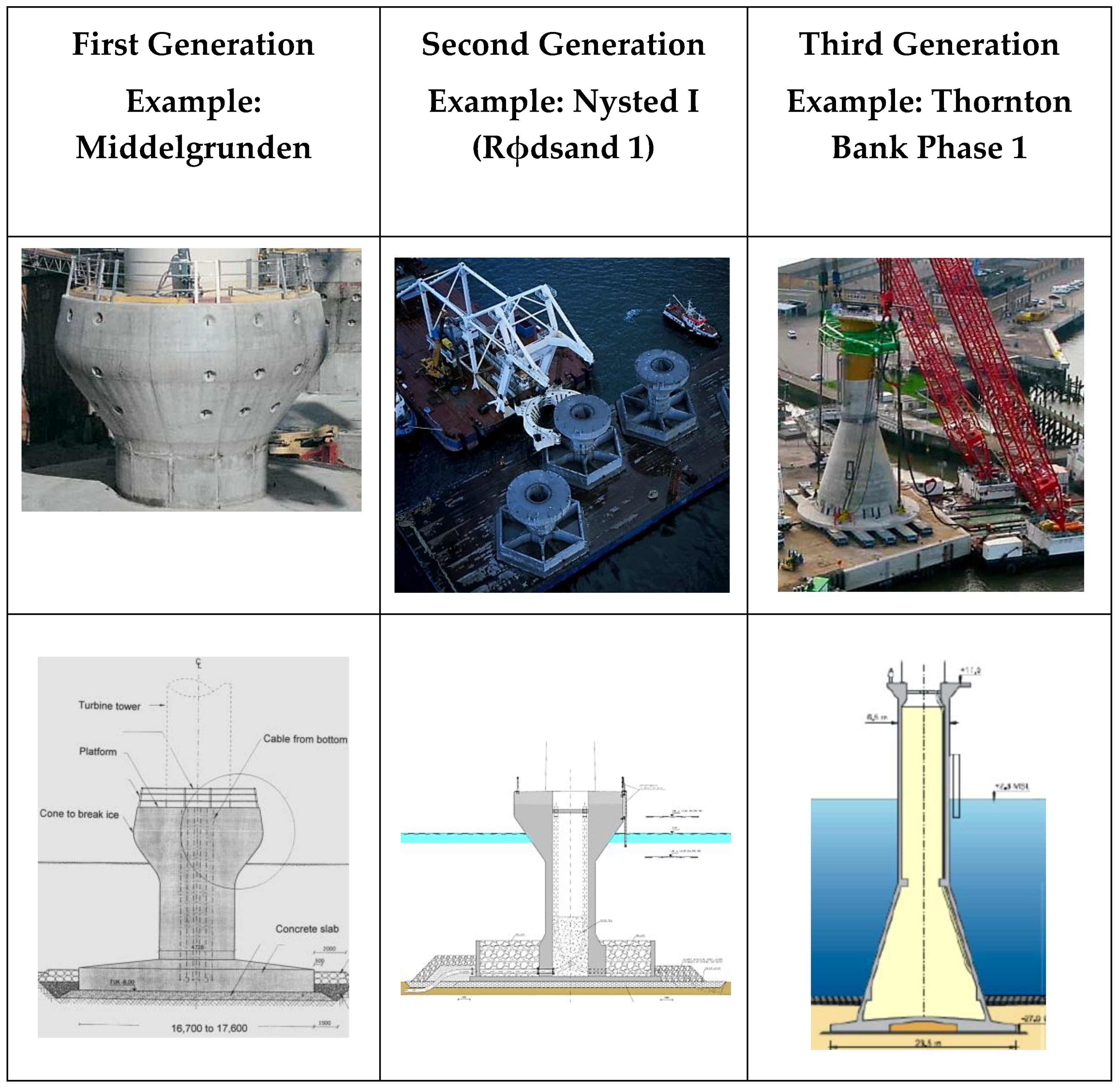
As a result of the analysis carried out here, a basic classification of the different GBS types is included. This classification includes first-, second-, and third-generation types of GBS foundations.
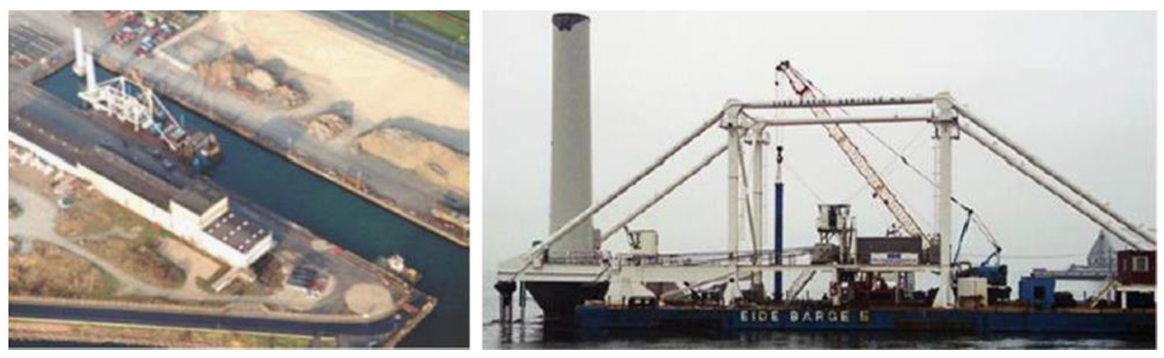
The first-generation GBS foundations correspond to the first offshore wind facilities with GBS foundations: Tunϕ Knob, commissioned in 1995 and located in between 4 and 7 m of water; and Middelgrunden (
Figure 1), commissioned in 2001 and located in between 3 and 6 m of water. This first generation also corresponds to the first designs that were made of this type of foundation for the offshore wind industry.
This type of GBS is a completely solid, reinforced concrete structure, without holes or cells. It is composed of a large-diameter slab; in the case of Middelgrunden, this is between 16.7 and 17.6 m and very thin. The said slab is attached to a small-diameter shaft that, in some cases, ends in the form of a cone as an icebreaker (
Figure 1).
Since it is a solid structure, the weight to be taken into account for the transport and installation is very high compared to the weight of a structure with the same geometry, but with incorporated holes or cells. This typology was possible designed because Tunϕ Knob and Middelgrunden offshore wind farms were built in locations with very shallow water—between 3 and 7 m of water depth. While this type of concept can be considered to be a suitable solution for shallow depths, it is not viable for sites in deeper water. The main problem is that, in deeper water, the design of these structures, which work based on their own weight once they are in operation, leads to greater weights than if they are designed to incorporate holes or cells. These heavy structures are not easy to transport to the site or to install, as they need barges and cranes with special requirements. This makes this first generation of GBS unprofitable for greater depths.
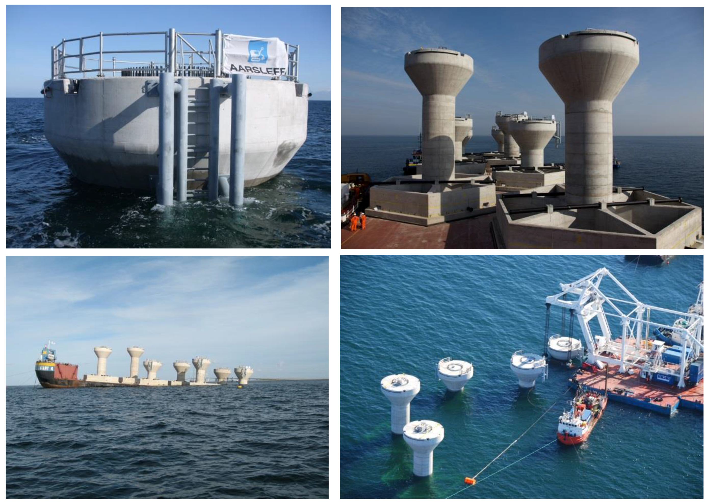
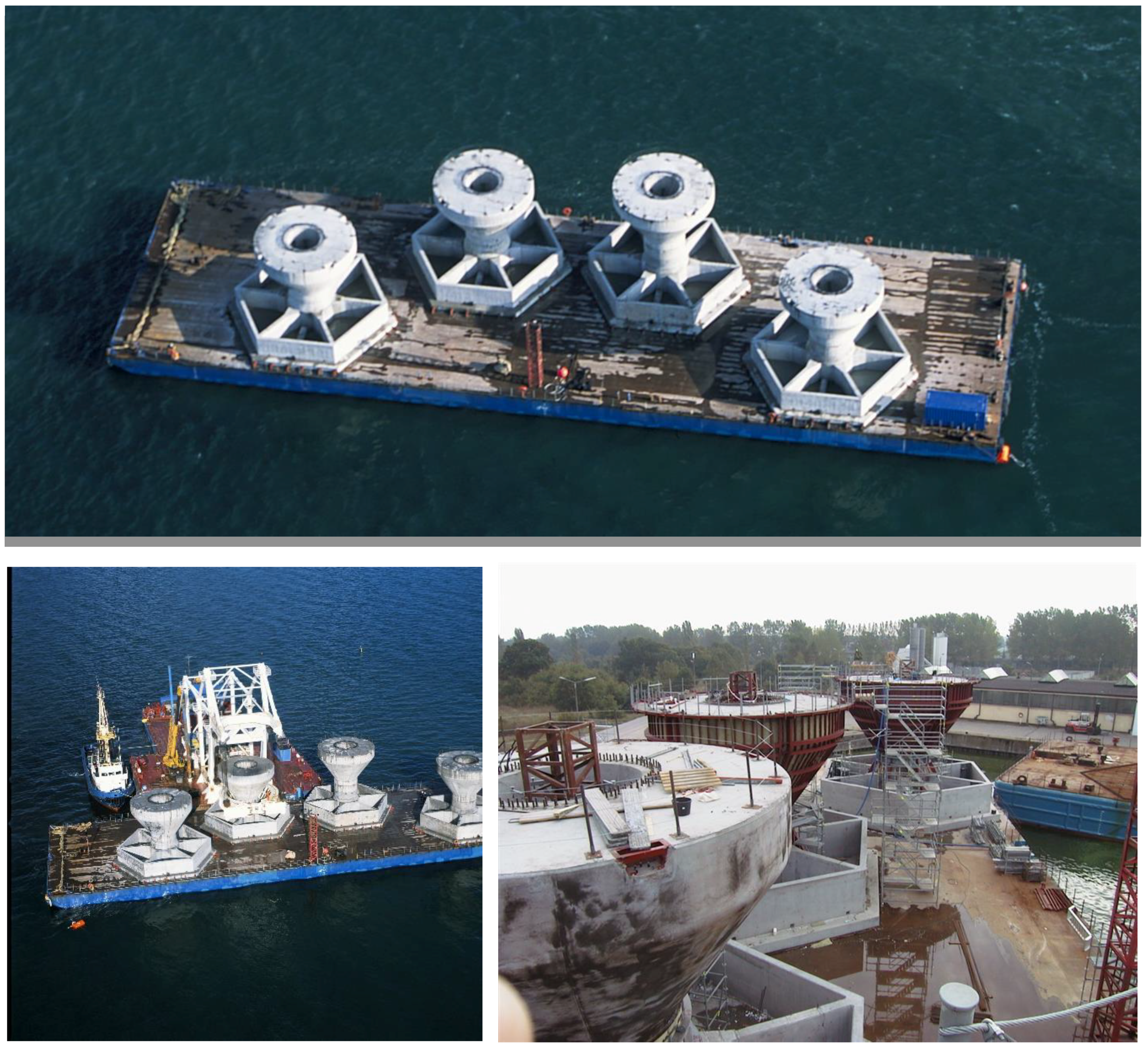
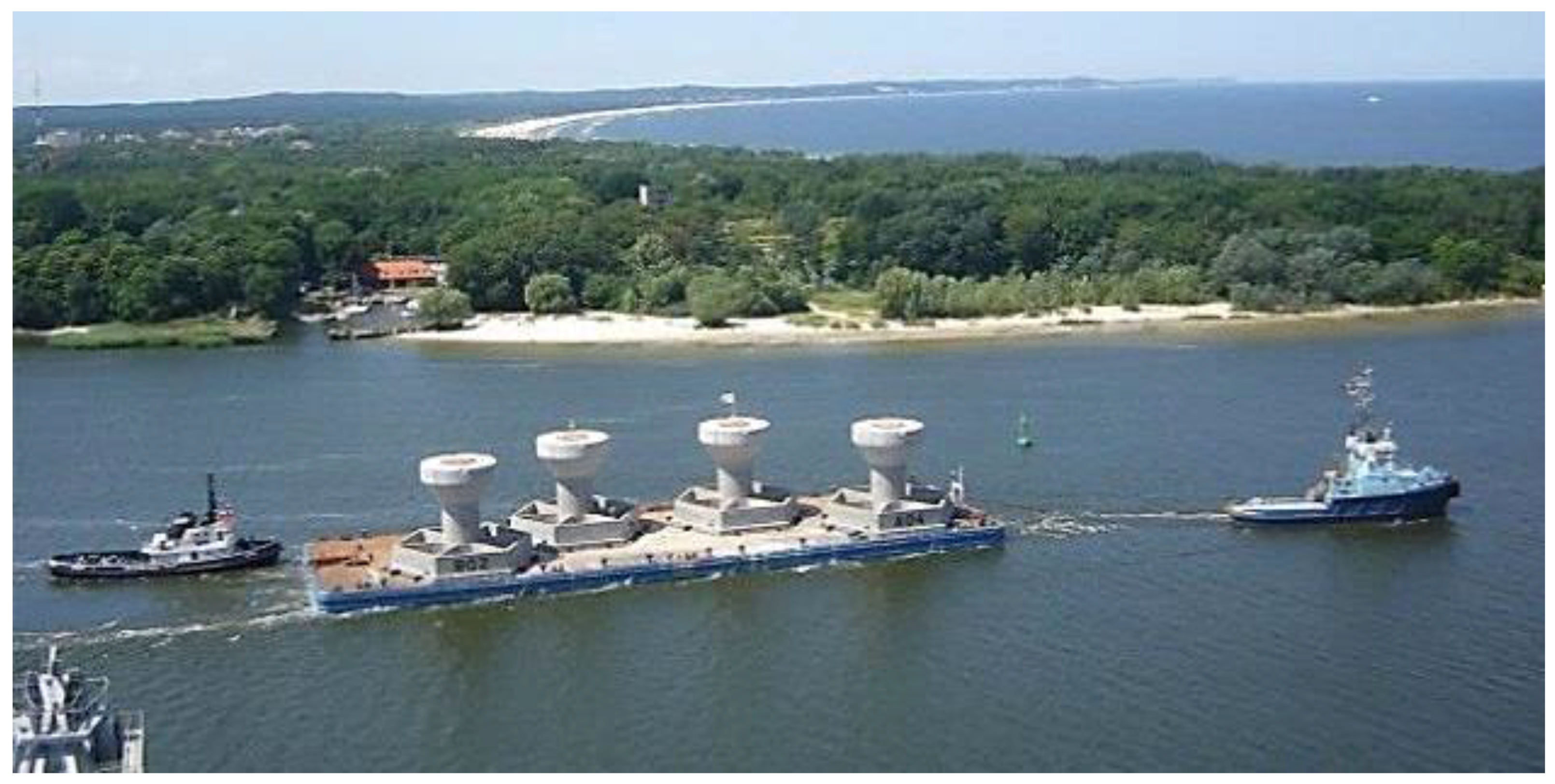
Following this, designs corresponding to the second generation of GBS foundations were developed. Examples of this second generation are: Nysted I (or Rϕdsan I) (
Figure 2), commissioned in 2003 and located in between 6 and 10 meters of water; Lillgrund (
Figure 3), commissioned in 2007 and located in between 4 and 13 meters of water; Sprogϕ (
Figure 4), commissioned in 2009 and located in between 10 and 16 meters of water; Rϕdsan II (or Nysted II) (
Figure 5), commissioned in 2010 and located in between 6 and 12 meters of water; and Kårehamn (
Figure 6), commissioned in 2013 and located in between 6 and 20 meters of water.
This type of GBS foundation is composed of a flat slab and a shaft, similar to that of the first generation but with the main difference being that the slab contains holes or cells. This means that if the weights of a first- and second-generation GBS structure were to be compared, both with the same geometry, the weight of the latter would be much lower. This lower weight allows more units to be transported in the same barge, from the port to the final location, in one trip. In addition, the cranes used in installation have less demanding requirements. Once the GBS foundation is installed, the holes or cells are filled with ballast, thus achieving the final design weight of the structure that allows it to be stable and resistant to loads.
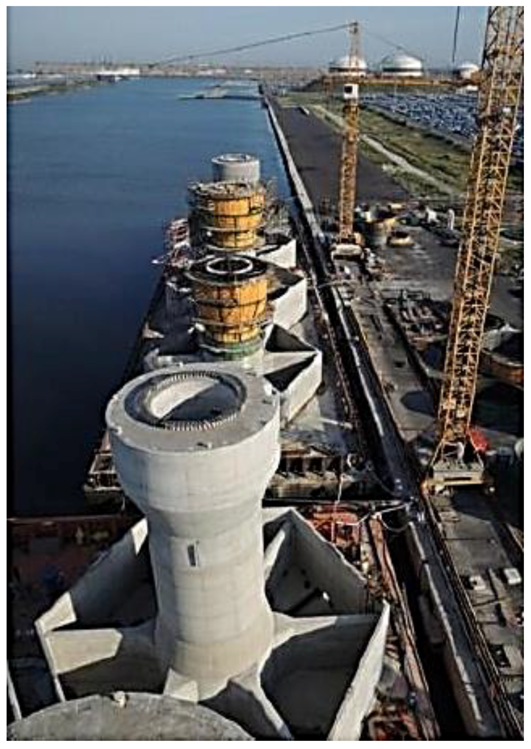
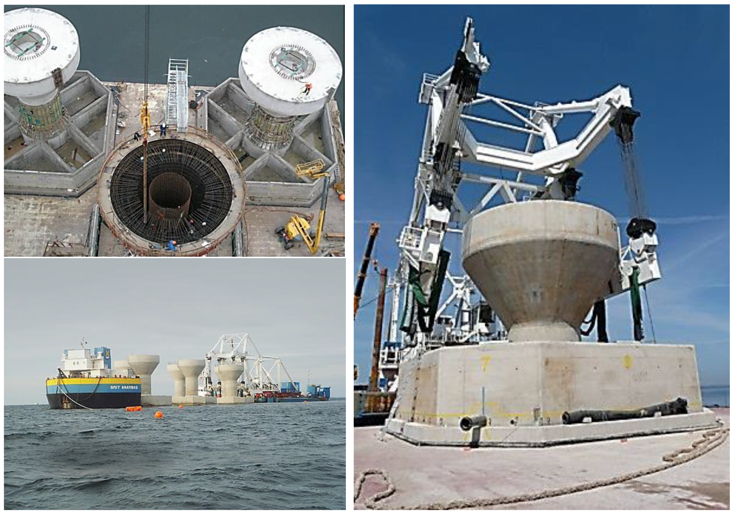
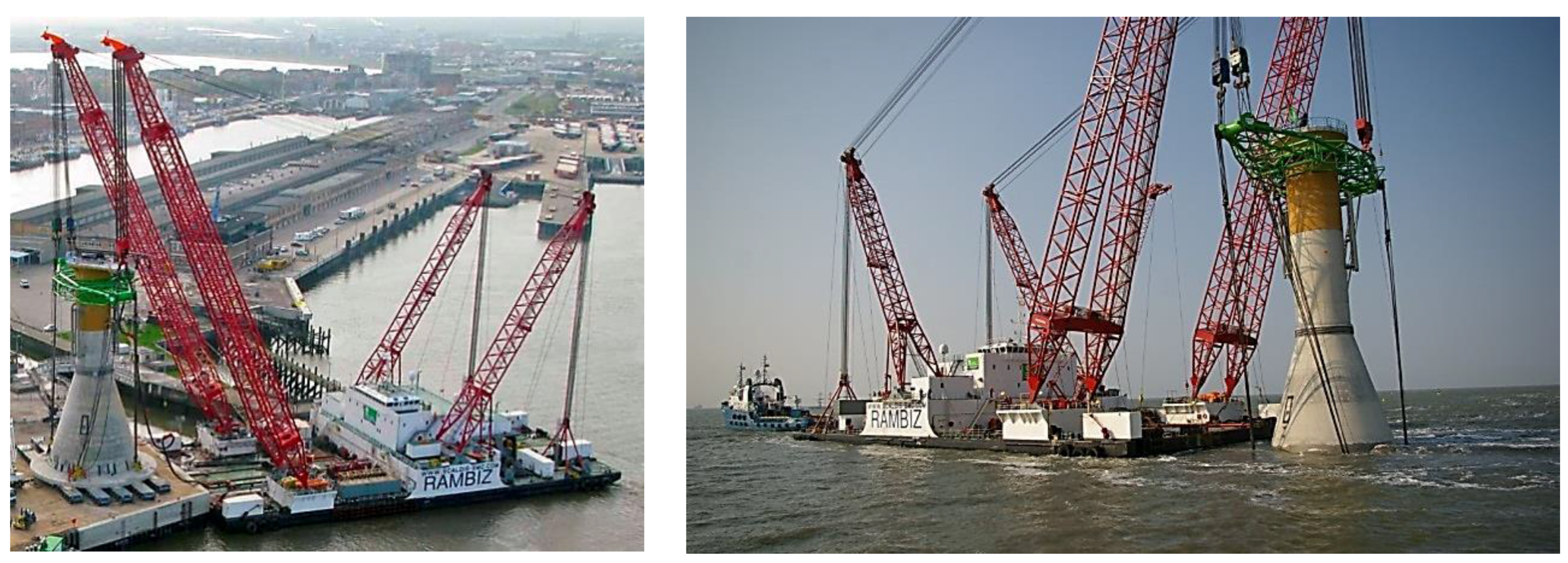
The third generation of GBS foundations are the latest concepts that were built. An example of this generation is the first phase of the Thornton Bank offshore wind farm (
Figure 7), commissioned in 2009 and located in between 13 and 20 meters of water. As can be seen in that figure, the structure has a conical shape in the lower part and a vertical shaft in the upper part. The structure is mostly hollow inside, not only the slab or lower part. This structure was designed to be transported using a semi-floating method, thus reducing the weight of the structure for that phase, which lowers the requirements of the transport vessels and cranes used in their installation. Once the structures are in place, the hollow area is filled with ballast, to provide the necessary weight to support the loads.
The classification proposed for the GBS concepts used up to now in offshore wind farms already in operation is shown in
Figure 8, which includes an example, a conceptual draft, and a photo of the different types of GBS foundations that correspond to the first, second, and third generations.
3.2.2. New Concepts of GBS Foundations
Now that the different concepts of operational offshore wind farms have been outlined, the following sections concern new types of GBS foundations that are in the research phase. Most of these new concepts are based on the F2F (floated to fixed) concept, which refers to a structure that behaves as a float during the transport phase from the port to its final location, and during the installation phase. During transport, it is necessary to have the support of small tugboats. By floating the structure, the need for vessels for transport is eliminated, except for the tugboats, thus reducing the cost of that phase. Some of these types of GBS foundations need special-purpose vessels, with the objective of transporting and installing the GBS structure and the wind turbine generator (WTG) together, with the WTG being pre-assembled in the port.
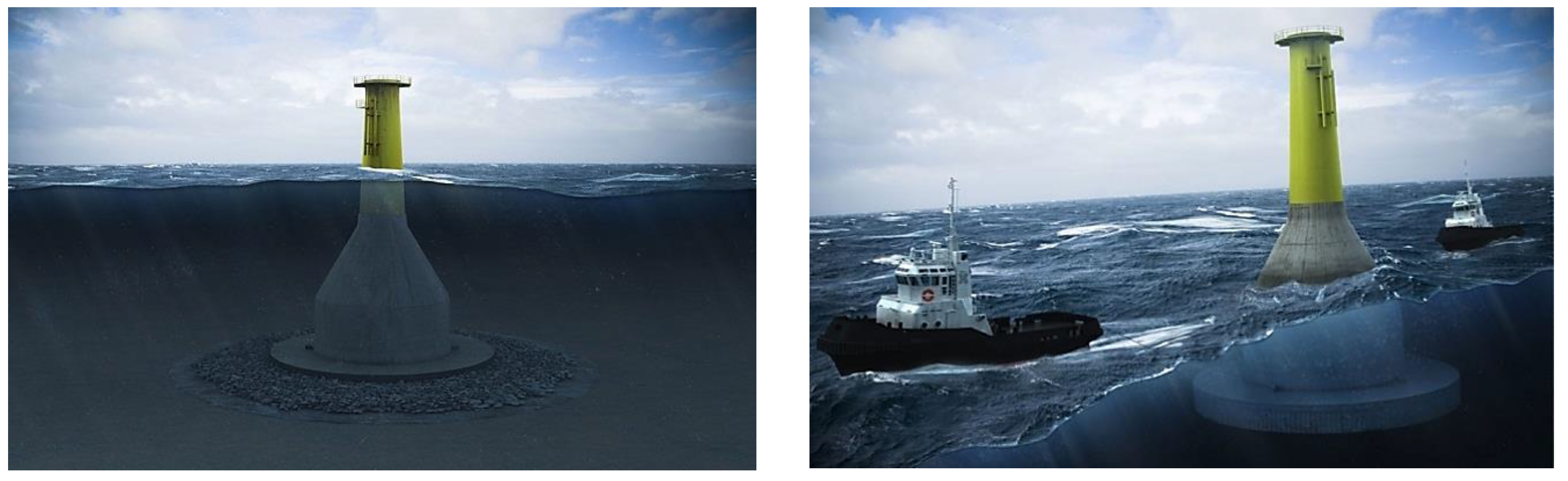
Crane-Free Gravity Base (Seatower)
The crane-free gravity base concept is a concrete structure with a relatively thin slab, an intermediate-length conical part, and a cylindrical shaft in the upper part. This concept was designed to be transported by its own flotation ability, so it is hollow inside, for which it needs the support of tugboats (
Figure 9). It avoids the use of an expensive and weather-sensitive crane. According to Reference [
23], this concept has been optimized for the logistics, from the manufacturing through to the decommissioning process.
Gravitas Gravity Base (Arup/Costain/Hochtief)
The gravitas gravity base concept is shaped similarly to the crane-free gravity base type, also having a relatively thin slab, intermediate-length cone, and cylindrical shaft in the upper part. This structure is also self-floating and can be transported to its final location only with the assistance of small tugboats. According to
www.arup.com, some characteristics of this concepts are: It is a reinforced concrete and ballasted gravity structure; it can be deployed in water depths up to 60 m; it can hold turbines generating up to 8 MW; it requires minimal seabed preparation because it can accommodate existing seabed slopes and surface sediments; its skirt has variants to suit specific seabed sediment conditions; the collar design for the turbine mast connection can accommodate an ~2° vertical alignment tolerance; there is the potential to repower it without replacing the foundation; the concrete base is configured for rapid construction using available construction skills; its construction is an onshore activity, which is tailored for ease of subsequent installation; it does not required deep water (10 m draft) for construction; the foundations are self-buoyant for ease of deployment to the wind farm location; it uses available and abundant standard tugs to install the foundations; installation is done by sinking, through a controlled influx of water, followed by sand/aggregate ballasting; and it includes scour protection, designed for minimum maintenance over the design life of the wind farm [
24].
The key figures for a 35-m water depth, central North Sea environment conditions, and 6 MW output are:
Air-gap concrete structure: 20 m.
Hub height above LAT (Lowest Astronomical Tide): 90 m.
Base outer diameter: 34 m.
Outer diameter, caisson: 31 m.
Outer diameter, top of shaft: 6 m.
Concrete volume: 1919 m3.
Steel reinforcements: 720 tons.
Strabag Gravity Base (STRABAG)
STRABAG has two different gravity-base concepts. Both of them have a geometrical slab and a cylinder in the upper part. The concepts have in common joint transportation and installation of the foundation and the wind turbine generator, with preassembly being performed in port, thus reducing the number of operations carried out at sea during the installation phase. To be able to carry the floating foundation and wind turbine together, a specifically-purposed vessel is used, called STRABAG Carrier [
25].
According to
www.strabag-offshore.com, both these concepts use the pre-stressed concrete technique, they are suitable for water depths up to ~45 m, and they can be completely disassembled.
GBF Gravity Base (Ramboll/BMT Nigel Gee and Freyssinet)
The GBF gravity base concept is a concrete structure with a circular slab, a conical intermediate part, and a relatively small-diameter cylinder shaft in the upper part. This concept is not self-floating and requires a specific barge for the transport and installation of the GBS structure and the wind turbine generator together. This specific barge is called a transport and installation barge (TIB) [
26].
The tower, nacelle, and rotor are assembled in the port quay before being lowered into the water. The TIB is ballasted down to the level of the base, then, upon connection, will refloat to the transportation depth. This concept was developed with the support of the Carbon Trust.
According to Reference [
27], this type of foundation is suitable for water depths between 20 and 55 m, many seabed conditions, a distance offshore between 2 and 200 miles, and turbines with a unit power between 3 and 10 MW.
Other Gravity Base Structure Concepts
Other gravity base structures are described in Reference [
28], both of them having similar shapes to the abovementioned concepts. These are, respectively, concepts from a collaboration between BAM Wind Energie and Van Oord, and the consortia of Skanska, Smit Marine Projects, and Grontmij. Both have two different parts—a slab and a shaft—and both are cylindrical, with a smooth transition between both with a conical shape.
4. Conclusions
A review of the different operational European offshore wind farms with GBS foundations was carried out in this study. In total, there are only 13 of these, and they are located in Denmark, Germany, Sweden, Finland, and Belgium. The deepest water in all of those wind farms is 20 m, in the case of Thorntonbank Phase 1. Furthermore, it is important to note that since 2013, there have been no commissioned GBS facilities.
The current strength of the monopile in the offshore wind-power sector is evident, compared to other typologies. This is mainly due to the simplicity of the structure, which results in benefits during manufacturing, installation, and maintenance, as well as cost. With its 80% representativeness, the monopile has shown its clear dominance in the current market, where most sites have a water depth not exceeding 20–30 m. At greater depths, there is a battle to be more competitive between the XXL monopile, GBS, and jacket foundation types.
The different types of GBS foundations used in all the wind farms in operation in Europe were analyzed. Based on this analysis, a classification was proposed for the different types, which distinguishes between the first, second, and third generations.
Examples of first-generation GBS foundations are Tunϕ Knob and Middelgrunden. These are solid concrete structures, without cells or holes, corresponding to the first designs.
Examples of the second generation are Nysted I or Rϕdsan I, Lillgrund, Sprogϕ, Rϕdsan II or Nysted II, and Kårehamn. These foundations include holes or cells in the slab or lower part of the structure, which reduces their weight for transport and installation. Once the GBS structure is installed, the holes or cells are filled with ballast, achieving the final design weight that supports the design loads.
The only example of a third-generation structure is Thornton Bank. This concept has a conical shape with a hole or cell inside and not only in the slab or lower part, as in the second-generation models. This type of structure was planned to be semi-floating during the transport and installation phases, decreasing the weight of the foundation and reducing the lifting requirements. Once this foundation is placed on the seabed, the interior hole is filled with ballast to achieve the final design weight to support the design loads.
Other, nonproven concepts were analyzed in this study, some of them based on the F2F (floated to fixed) concept, which is a floating structure during the transport and installation phases, supported by small tugboats, which decreases the costs because of the self-buoyancy of the foundation and there being no need to use larger, more specific transport vessels. Another new concept needs special-purpose vessels to transport and install the GBS and WTG structures together, with the WTG being pre-assembled onshore. These transport vessels are designed specifically for each concept.
Some of these new concepts include the crane-free gravity base (Seatower), gravitas gravity base (Arup/Costain/Hochtief), Strabag gravity base (STRABAG), GBF gravity base (Ramboll/BMT Nigel Gee and Freyssinet), GBF gravity base (Ramboll/BMT Nigel Gee and Freyssinet), Rockmat (OFS: CETEAL/Cathie Associates/DVO), ocean brick system (Technical University Braunschweig), etc.
As mentioned above, new locations with greater water depths will begin a battle between the XXL monopile, GBS, and jacket types. The more real and well-analyzed options the market has, the more competitive this scenario could become. This is why it is expected that solutions similar to the third-generation concepts, characteristic of the first phase of the Thornton Bank offshore wind farm, will come online in the future, including more options to use F2F concepts where it is necessary to build special-purpose vessels.
The trend will likely be to have the entire wind turbine pre-assembled on the structure at the port, in order to reduce the number of operations carried out at sea, which involve greater costs and risks. The GBS concept is very interesting in that respect, and one example is the ELISA project in the Canary Islands, designed by Esteyco, which has a slab and a shaft, without a conical transition. The prototype for a 5 MW-output concept will use special-purpose vessels to help in the transportation of the entire GBS structure and wind turbine. As a nod to previous concepts, it has a telescopic tower and, using hydraulic jacks, manages to raise the different sections into their final positions, with the nacelle and rotor already installed on the last section of the tower.


