1. Introduction
To comply with the regulations introduced by the International Maritime Organization, there is increasing effort to improve the energy efficiency of vessels and reduce fossil fuel usage. WASP systems have become an innovative area of research that is gaining renewed importance in maritime transport due to their ability to reduce greenhouse gas emissions and increase the overall energy efficiency of ships. According to previous studies [
1,
2,
3], different wind sail technologies, rigid sails, rotor sails, suction wings, and kites have been developed and are being used to assist the main engine and reduce fossil fuel consumption.
Studies regarding WASP systems are mostly focused on the energy aspects of the sails using simulation-based investigations [
1,
2,
3]. The need for design optimization of sails, operational optimizations, hybrid propulsion systems, weather routing, standardized performance evaluation, etc., is emphasized. However, evaluations regarding sailing systems are limited to energy aspects rather than their effects on maneuverability, safety, structural evaluations, etc.
Studies aimed at improving the energy performance of WASP systems have mainly focused on system integration, aerodynamic design optimization, and route optimization. Tillig and Ringsberg [
4] evaluated rotor sail-assisted ship propulsion considering different environmental conditions and sail layouts on various vessels. Performance prediction programs were developed, which took ship resistance, wind profile, environmental conditions, and operational parameters into account, showing energy savings [
5,
6]. Furthermore, intelligent control systems were developed to efficiently operate the sailing system in coordination with the main engine [
7,
8]. Additionally, the effects of the kind of control implemented, such as heading control, course control, and speed control, were investigated and the importance of the speed controller was emphasized [
9]. When it comes to design optimization, Guzelbulut et al. [
10] optimized the shape of the parametric crescent-like airfoil. Yasuda et al. conducted numerical analyses of aerodynamic interactions in multiple sail configurations [
11]. Similarly, analyses of wake distortion in DynaRig sailing systems showed that aerodynamic efficiency can be tuned by properly arranging the configuration of sails [
12]. In addition to studies focusing mainly on sails, Plessas and Papanikolaou [
13] conducted a multiobjective optimization of the wind-assisted ships at all including hull resistance, wind and wave interactions, and forces generated by sails. Li et al. [
14] investigated the wind energy density in different areas on maps and found that fuel consumption and CO
2 emissions drop significantly in high-wind-energy areas. Rather than focusing on the efficiency of each system, Liu et al. [
15] proposed an integrated control method to determine optimal operating conditions.
Although numerous studies have examined the energy performance of sails, their latent effects have not been investigated in detail. Chowdhury et al. [
16] investigated the seakeeping performance of wind-assisted ships in different sea conditions using the computational fluid dynamics method. Due to side force generated by sails, leeway and heel angles, which increase the overall resistance dramatically, are observed [
17]. Similarly, the performance of rotor sails decreases due to the heel of ships [
18]. According to Jensen [
19], the maneuvering performance of wind-assisted ships varies depending on the wind direction and sea state as well as the trim settings of the sails. Although the effect of sailing systems on maneuverability has been investigated to some extent, further research is required to fully evaluate their performance implications. Apart from previous studies, this study focuses on the maneuverability aspects of wind-assisted ships and develops a control algorithm that improves the maneuvering indexes.
In the present study, we proposed a weighted objective function to determine the spin ratios of rotor sails, which allows for improving the maneuverability of wind-assisted ships in different environmental conditions. First, a turning test database was generated by using randomized weights and environmental scenarios. An ANN model was trained using the database to predict maneuvering performance. The weights were optimized using the ANN model to improve maneuvering indexes. Finally, the maneuvering performance of a wind-assisted ship with the proposed control algorithm was compared with that of a conventional ship and a wind-assisted ship with a thrust-maximizing sail controller. In
Section 2, the modeling of ship motion is presented. In
Section 3, the maneuverability performances of conventional and wind-assisted ships are compared, and the ANN model structure and training procedure and the effects of the proposed control logic on maneuvering are shown and discussed. In
Section 4, the overall evaluation and the main outcomes of the study are summarized.
2. Methods
The proposed methodology relies on the implementation of various rotor sail controller configurations on a Maneuvering Modeling Group (MMG) model to investigate and enhance the maneuverability of wind-assisted ships. First, the MMG model of the target ship, namely, KVLCC2, with four rotor sails was built. The main particulars of the target ship are given in
Table 1, where
is the length between the perpendiculars;
is the breadth of the ship;
is the depth;
is draft;
is the displacement volume;
is the center of mass with respect to the mid-ship coordinate system;
is the diameter of the propeller and
is the block coefficient. The parameters used in simulations were obtained from references [
20,
21,
22].
The equation of motion used in the MMG model is given in Equations (1)–(3), where
,
,
,
, and
are inertial properties;
,
, and
are velocity terms in the surge, sway, and yaw directions;
,
, and
are external forces and moment acting on the target vessel in the directions of surge, sway, and yaw; and
is the center of gravity with respect to mid-ship coordinate system. The force term subscripts
,
,
,
,
, and
indicate the corresponding components: hull hydrodynamics, propeller, rudder, hull–wind interaction, hull–wave interaction, and wind sailing system, respectively.
Hull hydrodynamics is composed of straight moving resistance,
, which is obtained using the Holtrop–Mennen method [
23], and maneuvering forces, as given in Equations (4)–(6). The forces and moments acting on the target ship due to maneuvering are defined based on the fourth and third orders of polynomials of the nondimensional sway speed,
, and yaw rate,
, where
is the resultant speed and
is the length between perpendiculars.
is the density of seawater and
is the ship draft. The parameters of
,
,
,
,
,
,
,
,
,
,
,
,
,
,
, and
are called as hydrodynamic derivatives.
It was assumed that the propellers only generate thrust, not side forces or yaw moment. Propeller thrust,
, was calculated using Equations (7)–(9).
is the thrust deduction factor;
is the propeller revolution;
is the diameter of the propeller;
is the thrust coefficient, depending on the advance ratio,
.
The steering forces and moment generated by the rudder are defined in Equations (10)–(12).
,
, and
are the interaction coefficients between the hull and rudder.
is the position of the rudder with respect to the mid-ship coordinate system.
is the normal force generated by the rudder and
is the rudder angle.
is defined in Equation (13) based on the flow speed around the rudder (
), the rudder area (
), the lift gradient coefficient (
), and the effective inflow angle (
).
The interaction between wind and hull was modeled according to Equations (14)–(16), where
is the density of air;
and
are frontal and lateral projected area;
and
are apparent wind speed and direction; and
,
, and
are the force coefficients determined by Fujiwara et al. [
24].
Similarly, the interaction between hull and wave was formulized as Equations (17)–(19) based on the model and data used in Yasukawa et al. [
22].
is the gravity of earth;
is significant wave height; and
,
, and
are coefficients determined by the total speed of ship,
; wave period,
; and wave direction,
.
The forces generated by the single rotor sail and the required power were calculated according to Equations (20)–(22), where
is the lift force;
is the drag force;
is the sail input power;
is apparent wind speed;
is the projected sail area; and
,
, and
are the lift, drag, and power coefficients, respectively. Then, the lift and drag forces were transformed into the mid-ship reference frame, as in Equations (23) and (24), where
is the apparent wind direction.
The lift, drag, and power coefficients of rotor sails,
,
, and
, are characterized by the spin ratio of the rotor sail. In the present study, a polynomial regression model used in previous studies [
4] was used to express the relation between aerodynamic coefficients (
) and spin ratio,
. The spin ratio of the rotor sail is usually optimized to maximize the net power depending on the environmental conditions based on Equation (25).
However, it should be noted that rotor sails not only reduce fuel consumption but also can enhance the maneuverability of the ship under real environmental conditions. To determine the optimal spin ratio, the objective function was reformulated as shown in Equation (26). Here, the coefficients of
,
, and
are the weights that should be adjusted depending on the environmental conditions.
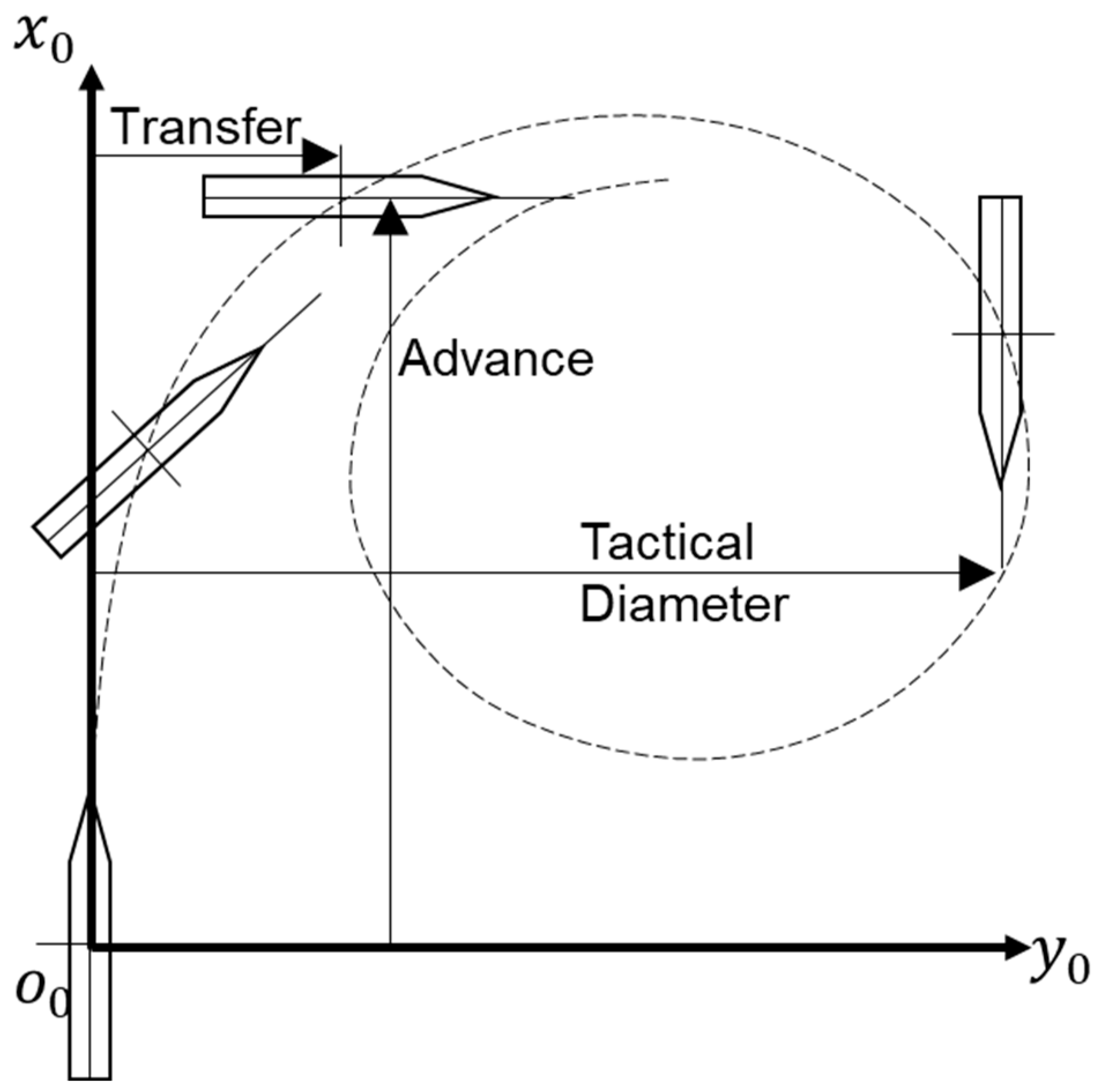
There are several standard tests to evaluate the maneuverability of ships, e.g., the turning test and zigzag test. While advance, transfer, and tactical diameter are critical metrics in turning tests, as shown in
Figure 1, overshoot angles and response time are critical metrics in zigzag tests.
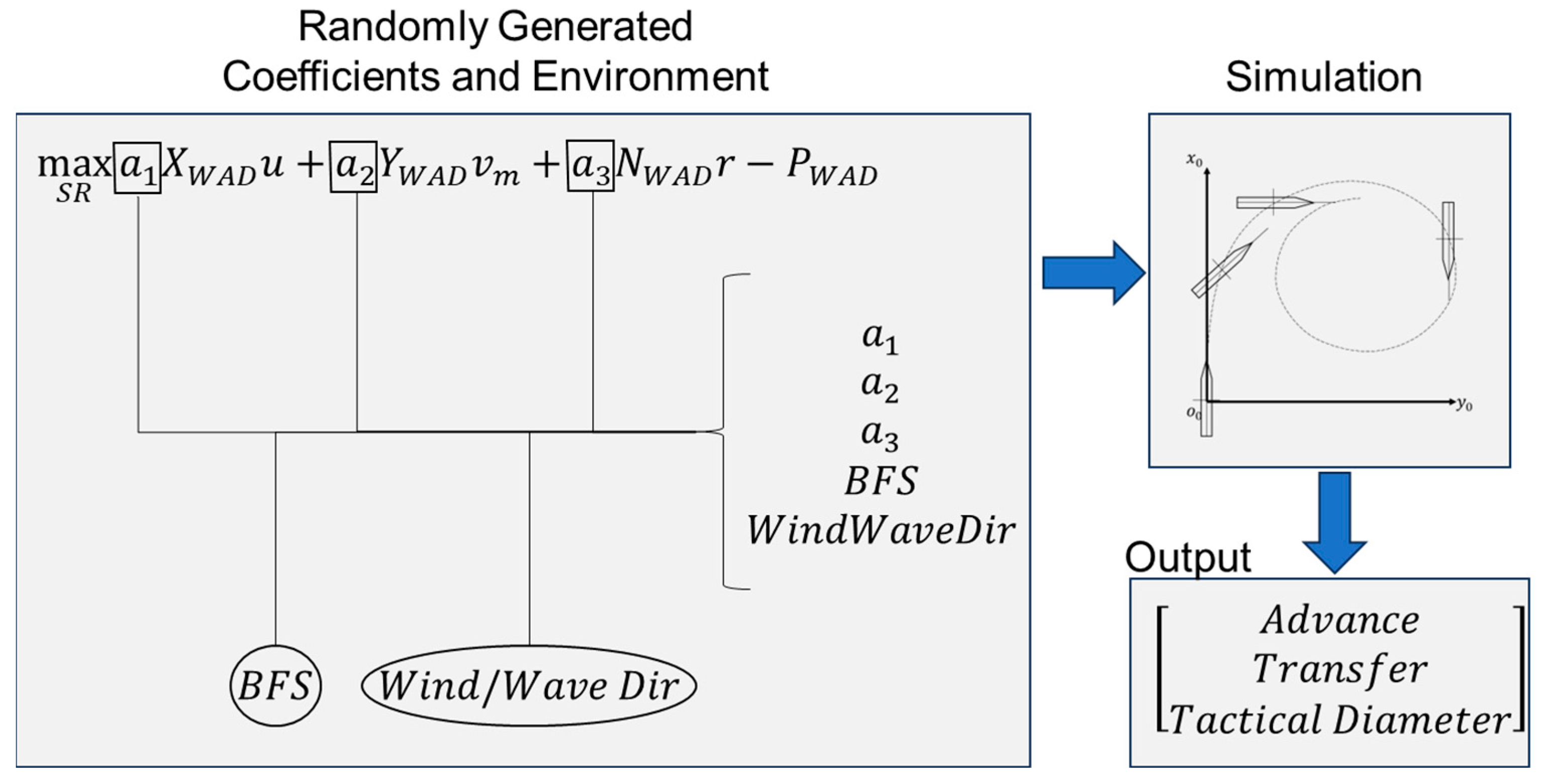
First, randomly varying coefficients within the range of −1 to 1 and random environmental conditions based on the Beaufort scale (BFS) and wind/wave direction were generated to determine how the coefficients of , , and should be tuned depending on the environment. Then, all randomized values were implemented and +35/−35 turning tests were simulated. A surrogate model was created using 5000 datapoints for each turning direction to predict the effect of given weights (, , and ), BFS, and wind/wave direction on the turning indexes of transfer, advance, and tactical diameter. Finally, the optimal coefficients of , and were found depending on BFS and wind/wave direction and an ANN model, which determines the optimal coefficients of , and for given BFS and wind/wave direction, was created.
3. Results and Discussion
The presented study proposes a new controlling approach for wind sails to improve the maneuverability performance for safety, although they are commonly used to provide additional thrust to reduce the demand on the main engines. Thus, we started with an investigation of how sails affect the maneuverability performance through turning tests under different environmental conditions.
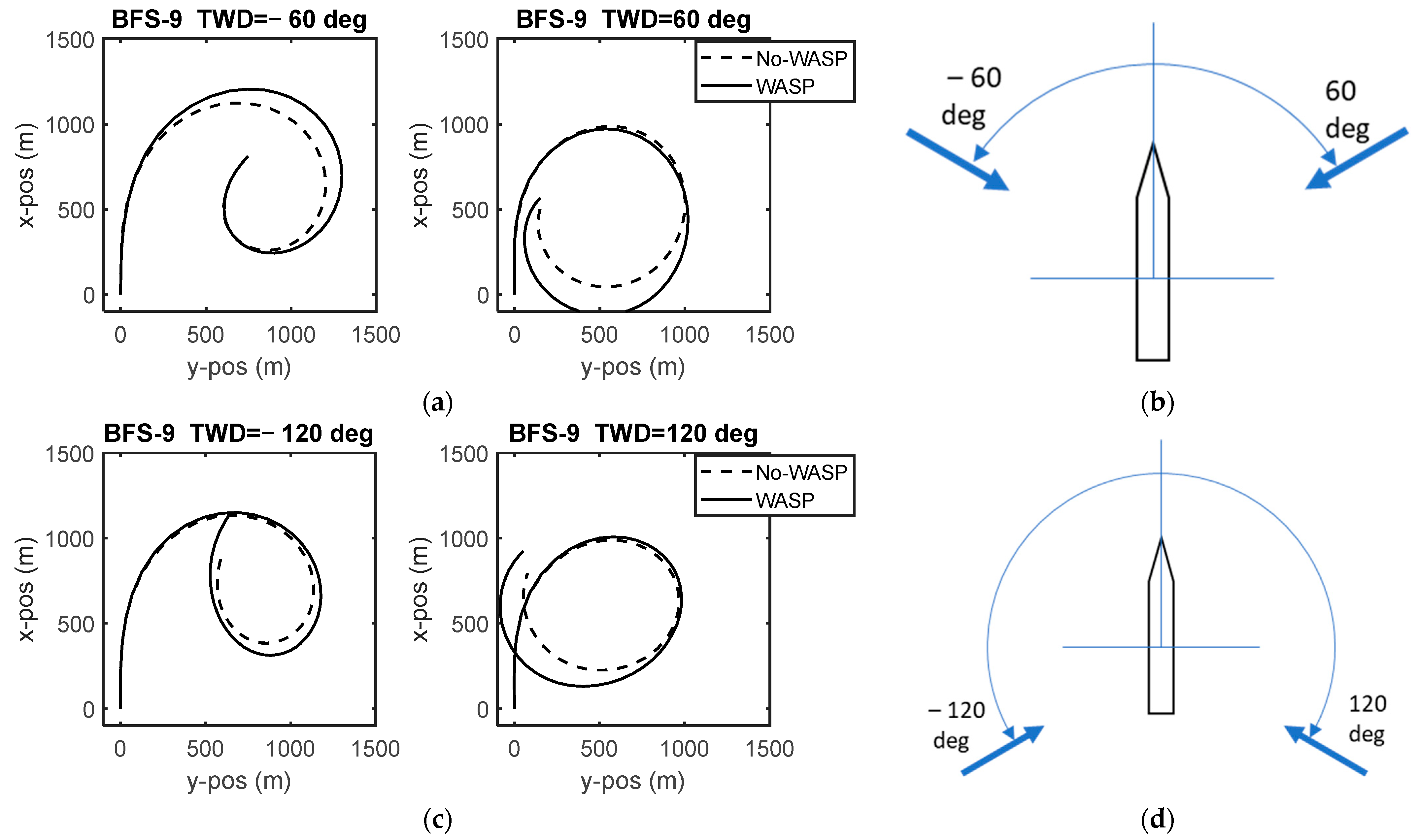
Figure 2 shows a comparison of a conventional ship, KVLCC2, and wind-assisted ship, KVLCC2, having four rotor sails with a thrust maximization approach for a BFS of 9 and wind/wave directions of ±60 and ±120 degrees. It was found that advance, tactical diameter, and transfer generally increased when the thrust maximization approach was implemented, regardless of the environmental conditions. Advance, transfer, and tactical diameter are found to increase by up to 7.3%, 11.9%, and 6.3%, respectively. Since the thrust maximization approach finds the optimal spin ratio by maximizing the difference between the thrust power of the sails and steady power required for a rotor sail to operate, it increases the ship speed during maneuvering and reduces the maneuverability performance.
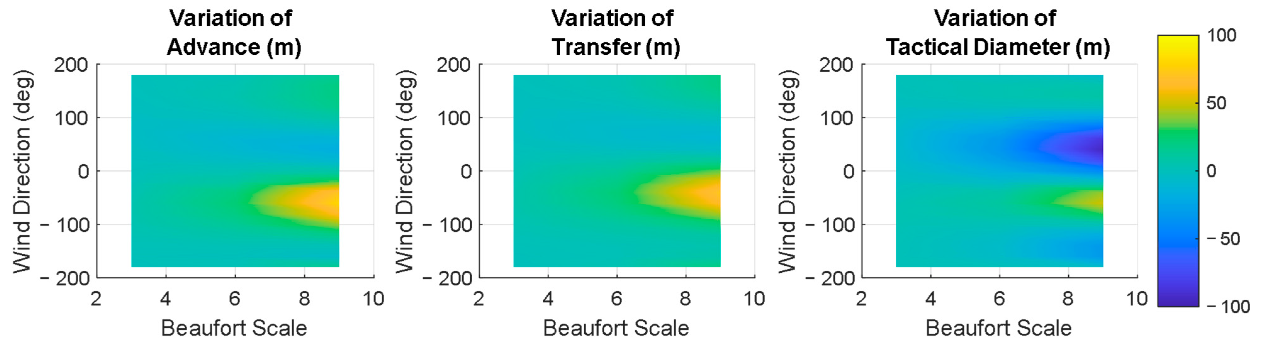
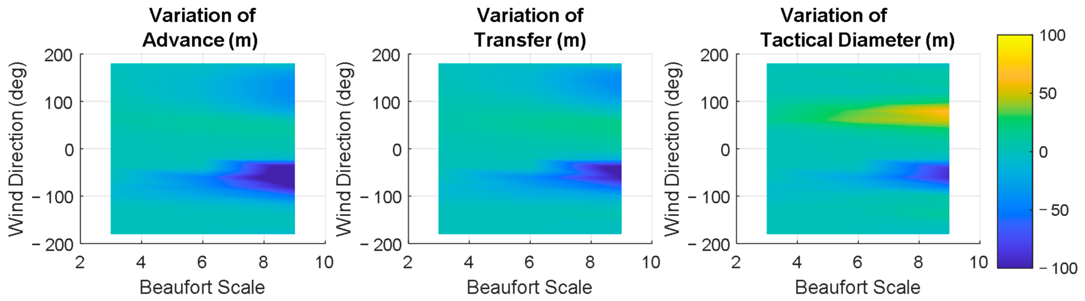
Then, the evaluation of maneuvering performance was expanded to include different BFS and wind/wave directions. Numerous simulations in MATLAB R2024b/Simulink were used to show how advance, transfer, and tactical diameter change depending on BFS and direction, as shown in
Figure 3. When environmental conditions become more severe, the effects of sailing systems on the maneuverability performance indexes increase. When the ship turns to the starboard side and wind comes from the port side (negative wind direction), advance and transfer significantly increase. On the other hand, wind coming from the starboard side (positive wind direction) reduces the tactical diameter due to the side forces generated by the sails.
As shown in
Figure 2 and
Figure 3, the sailing systems generally reduce the maneuverability performance and operational risk increases if the thrust maximization approach is implemented. This study presents an alternative control algorithm for sails that considers both energy efficiency and safety. When maneuverability is not required but energy contribution is expected, maximizing thrust becomes the objective function needed to find the spin ratios of the rotor sails. When maneuverability is required, the objective function given in Equation (26) can be used to determine the spin ratios. The coefficients
,
, and
given in the equation should be adjusted according to environmental factors and focus on improving the ship’s maneuverability. Therefore, a database was first created as shown in
Figure 4 by randomly varying these coefficients within the specified range.
Subsequently, the effect of weights on the motion was modeled using an ANN model based on the advance, transfer, and tactical diameter measured from the simulation results. The trained ANN model was then used to find the change in the optimal coefficients (, , and ) under different environmental conditions. Thus, an approach that improves maneuverability while taking environmental factors into account was obtained.
The ANN models used in the present study to turn starboard and port sides have inputs of the coefficients (
,
, and
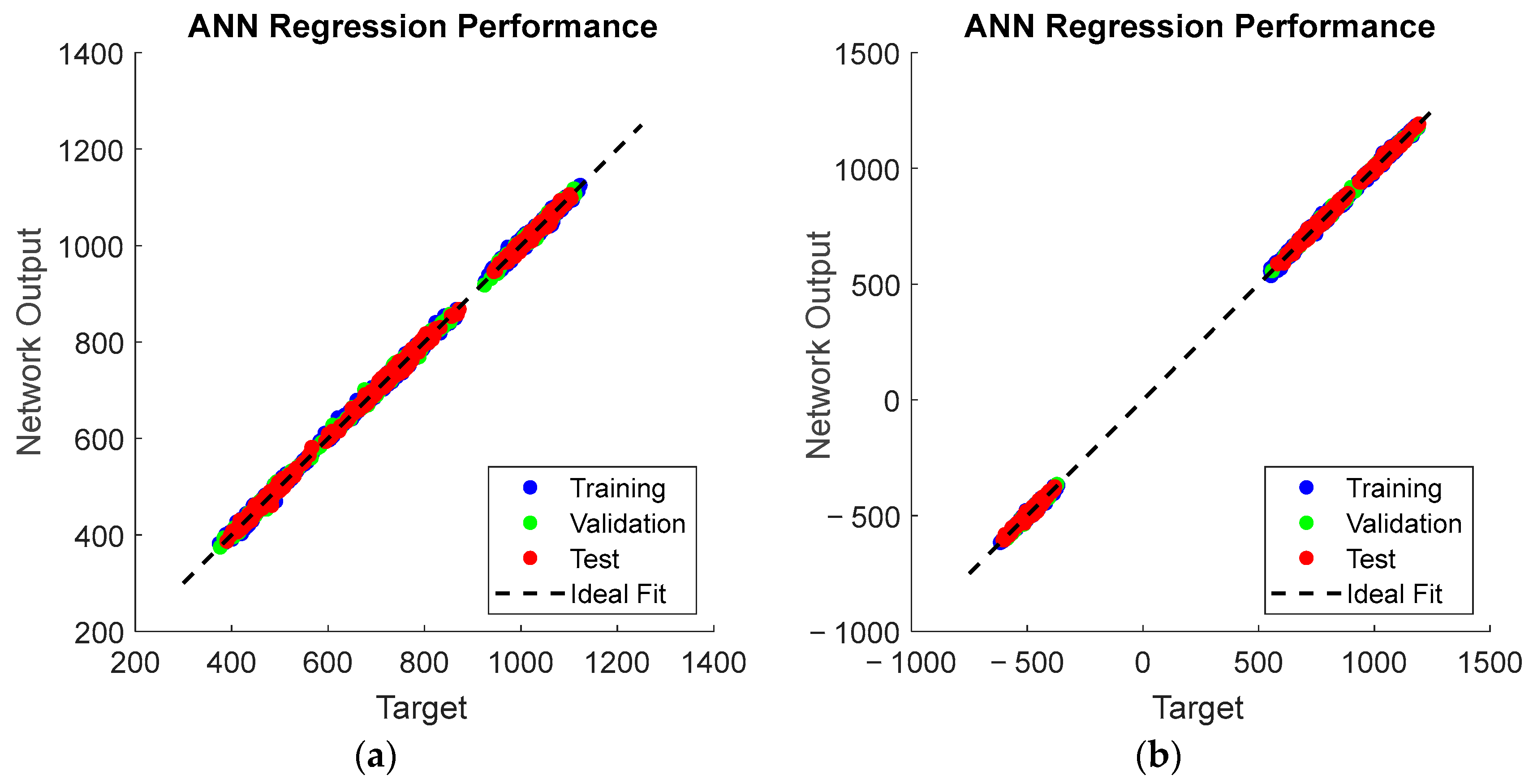
), BFS, and wind/wave direction and outputs of advance, transfer, and tactical diameter. To determine the number of hidden layers and the number of neurons in each hidden layer, various configurations were tested under the same conditions. Then, the architecture with two hidden layers containing eight and six neurons was selected, considering a trade-off between accuracy and complexity. The network was trained using the Levenberg–Marquardt algorithm. The tangent sigmoid activation function was used in the hidden layers. A total of 5000 samples were divided into training, test, and validation sets at ratios of 70%, 15%, and 15%, respectively. The mean squared error was used as the performance function. The regression performance of the training, test, and validation sets are shown in
Figure 5. The best validation performances were achieved at epoch 929 with a root mean squared error of 3.64 for starboard-side turning and an epoch 303 with root mean squared error of 4.86 for port-side turning. It was found that the ANN models capture the behavior of coefficients, the environment, and performance indexes, which is necessary to proceed with finding the optimal coefficients.
Then, an optimization problem was defined to determine which coefficients would improve the maneuvering performance using trained ANN models. The design variables of the optimization problem are the coefficients of , , and . The objective function was formulated as the multiplication of advance, transfer, and tactical diameter. Then, the optimal coefficients were found for a BFS of 3, 4, …, 9 and wind/wave directions of −180, −165, …, 165, 180 degrees using a genetic algorithm. The set of optimal coefficients were implemented into MATLAB R2024b/Simulink as a two-dimensional look-up table and sent to the rotor sail subsystem depending on the environmental conditions.
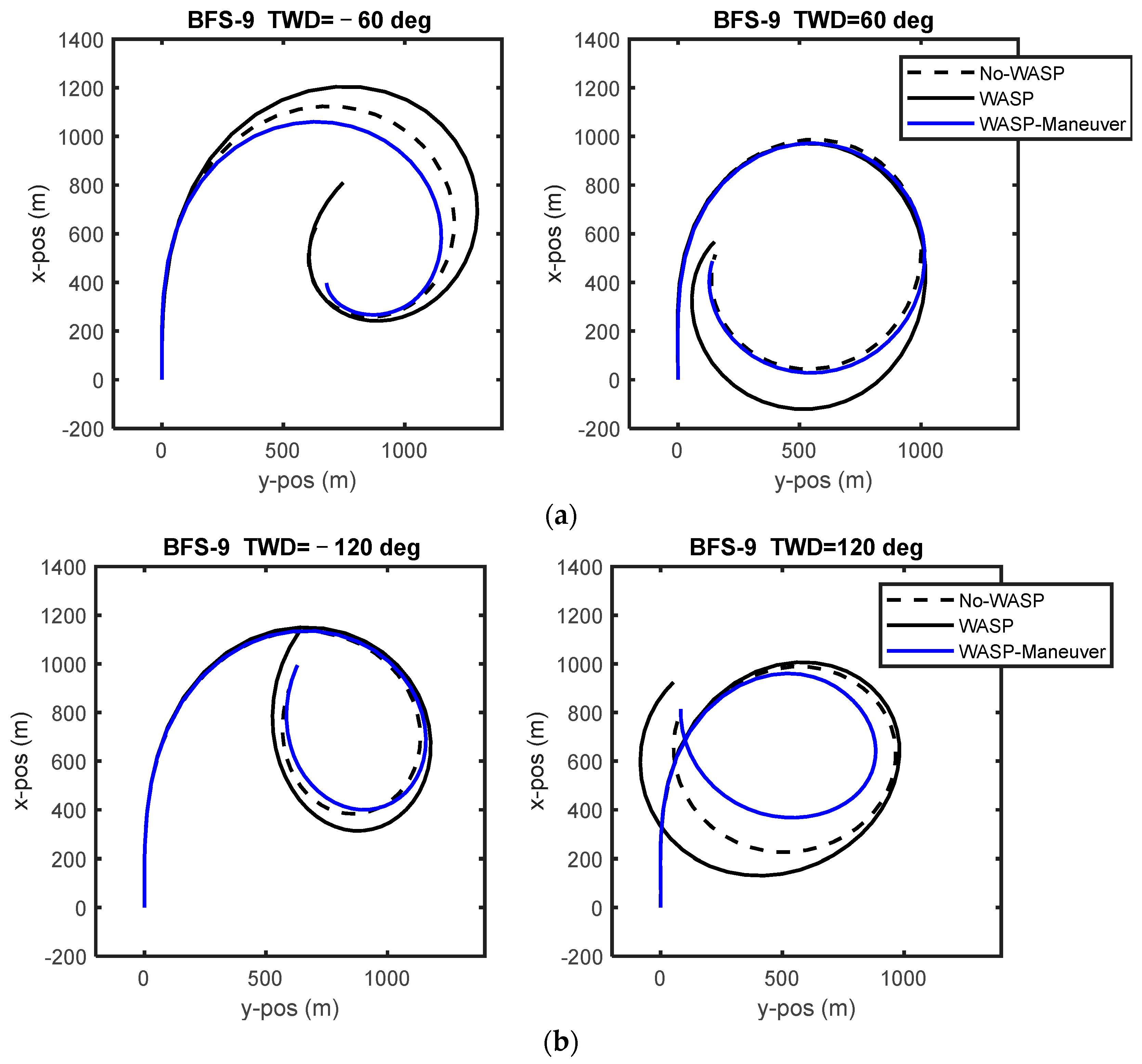
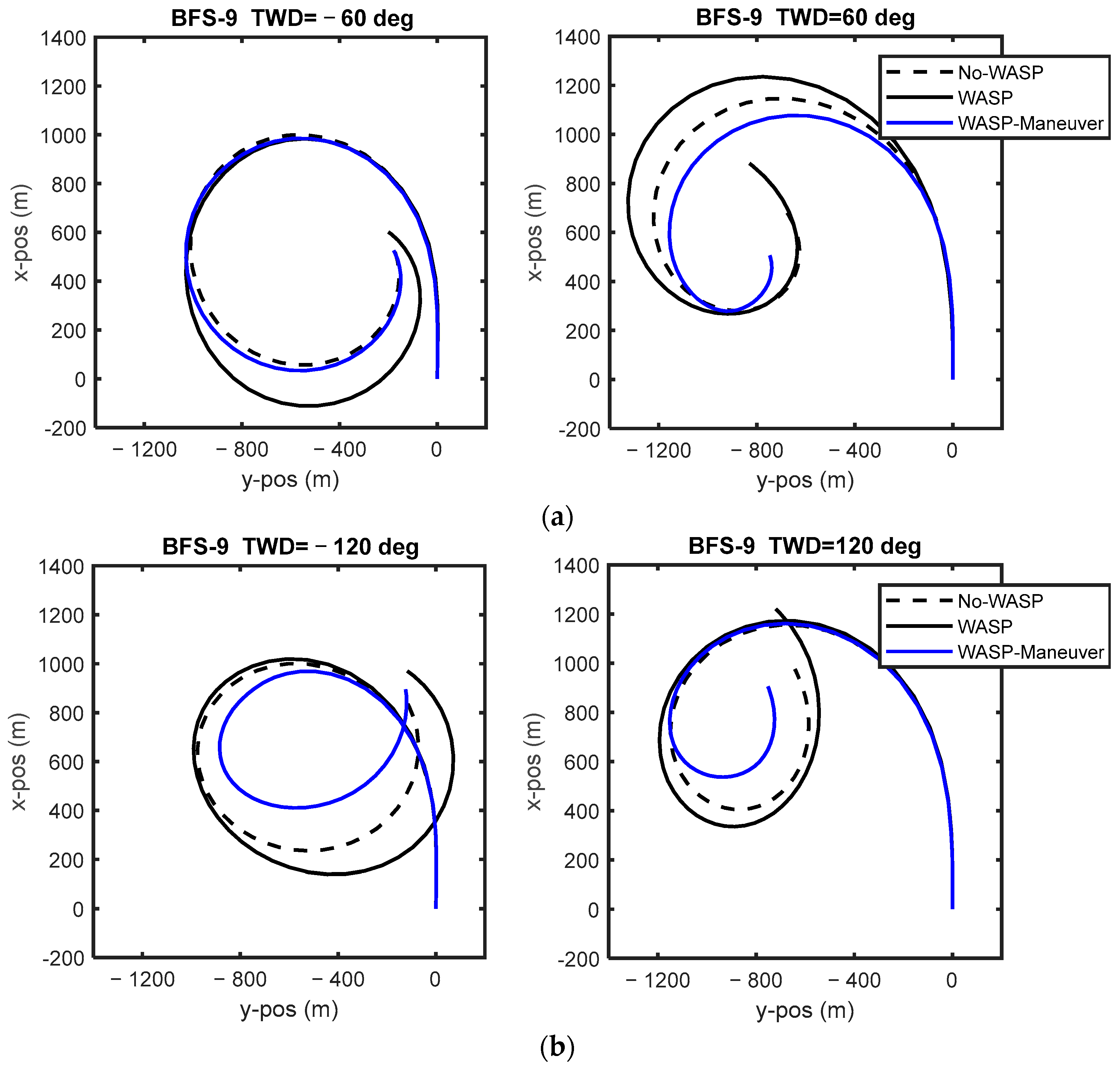
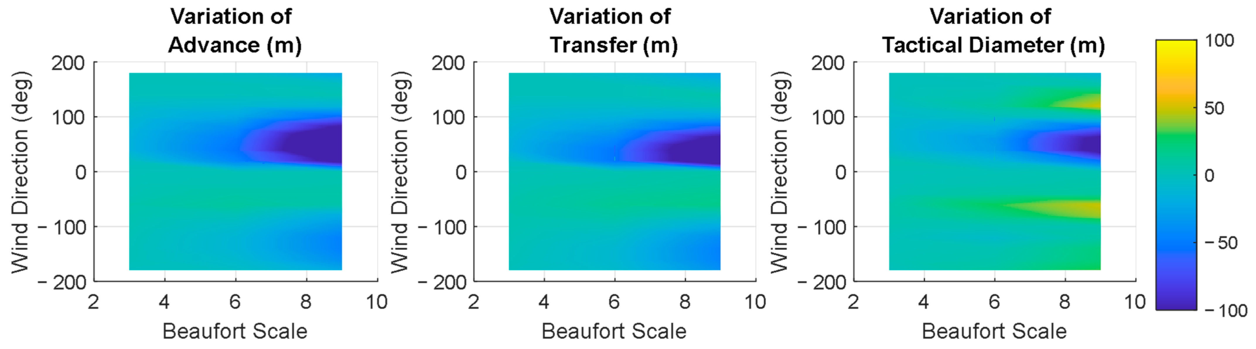
To understand how the proposed controlling logic affects the maneuvering performance, the behavior of ±35 degrees turning tests was simulated first. The results given in
Figure 6,
Figure 7,
Figure 8, and
Figure 9 show that the advance, transfer, and tactical diameter become even smaller than those for a ship without any sailing systems, making wind-assisted ships with the new control logic have better maneuverability characteristics. Due to the proposed sail controller, the advance, transfer, and tactical diameter dropped by up to 5.5%, 7.2%, and 5.3%, respectively, compared to the ship without any sailing systems, during turning to the starboard side, according to
Figure 6. In the generalized turning behavior to starboard side given in
Figure 7, significant reductions in each index were observed, especially at more severe environmental conditions and wind/wave directions of −60 degrees. On the other hand, the tactical diameter showed a slight increase at a wind/wave direction of 60 degrees.
Similar to turning to the starboard side, improvements in the maneuvering performance were observed when turning to the port side. It was found that the advance, transfer, and tactical diameter were reduced by 5.8%, 7.7%, and 7%, respectively, compared to the ship without any sailing systems, according to
Figure 8. Based on the general evaluation shown in
Figure 9, it can be said that the advance, transfer, and tactical diameter showed significant reductions, especially in severe environmental conditions and wind/wave directions of 60 degrees.
The proposed control strategy enhances the maneuverability of wind-assisted ships by reducing their advance, transfer, and tactical diameter. Although integrating sailing systems into conventional ships is primarily motivated by reducing greenhouse gas emissions, these systems also offer benefits in terms of maneuverability when a proper control logic is implemented. The present study introduces a new control approach for sailing systems, dividing the operation of sails into assisting the main engine and improving ship maneuverability. Proper adjustment of the weights in the objective function improves the target ship’s maneuverability due to an awareness of environmental conditions, thus supporting the latter use case.
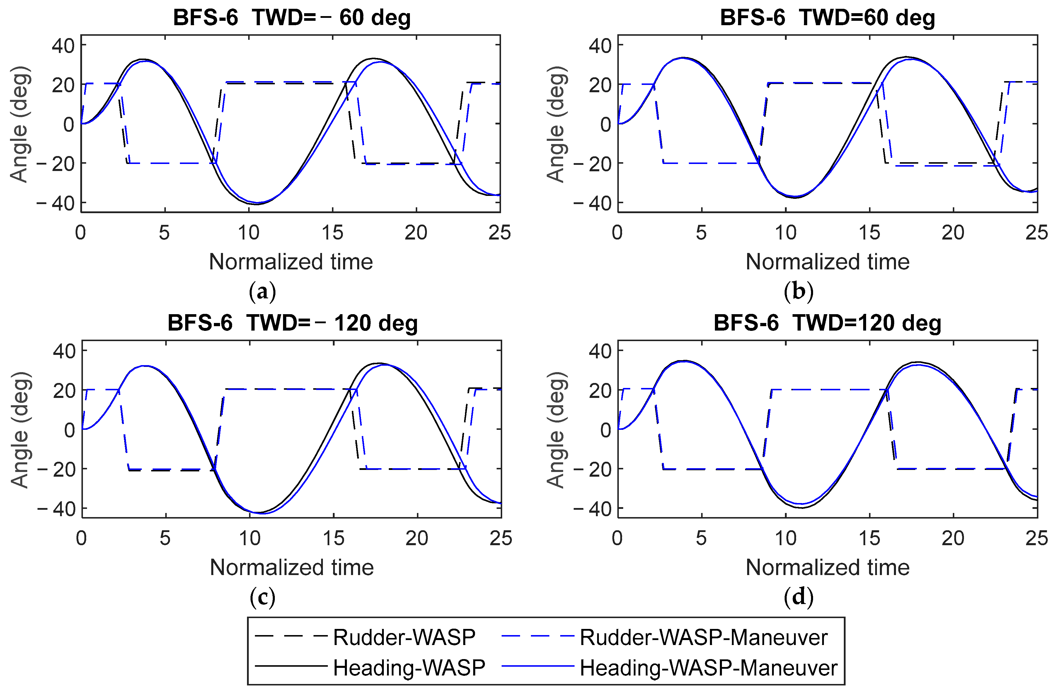
Since the ANN models were trained using turning tests, zigzag tests were also conducted using the proposed control logic to demonstrate the generalization capability of the proposed approach. The ANN models developed for the starboard and port sides were combined for the zigzag test, depending on the time derivative of the ship’s heading. If the time derivative of the ship’s heading was positive, the starboard weights were applied to determine the rotor sail’s spin ratio. If the time derivative of the ship’s heading was negative, the weights of the port side were applied. Then, the zigzag behavior of the wind-assisted ships with thrust maximizer control and the proposed controller for sails were simulated at a BFS of 6 and true wind/wave directions of ±60 and ±120 degrees. It was found that the first and second overshoot angles showed slight decreases in all conditions, as shown in
Figure 10.
The commonly used type of controller for sailing systems maximizes thrust to determine the angle of attack or spin ratio depending on the type of sail. On the other hand, there are many cases where sails can be used effectively. The proposed study includes all force and speed components of sailing systems. The mechanism behind the proposed control algorithm relies on properly distributing the weight of each force component. For example, the side force weight, , becomes −1 and the yaw moment weight, , becomes 1 during turning to the starboard side at side winds. In such conditions, the sails operate to increase side forces and moment to turn to the starboard side efficiently. Therefore, the proposed control algorithm significantly affects the maneuverability of wind-assisted ships by properly adjusting the weights to enhance maneuverability.
The proposed controller for the sailing system directly influences the maneuverability of wind-assisted ships. However, the biggest limitation of the proposed approach is that the trained ANN model only suggests parameters suitable for the target vessel, which restricts the adaptability of the approach to all vessels. Each vessel and sailing system pair requires a specific ANN model to be retrained.
The potential impact of sails can be increased by adding more sails and including the interaction models. Previous studies have shown that the asynchronous control of each sail improves the overall efficiency. Similarly, such interaction and control effects could be incorporated into the ANN model to further enhance the maneuverability of wind-assisted ships in moderate and severe environmental conditions.
In addition to improving thrust efficiency, reducing fossil fuel usage, and improving maneuverability performance, the use case of sails can be extended. For example, sails can be used as brakes in case emergency stops are needed, or the forces generated by sails can balance loads to increase the overall safety of ships. Proper adjustment of the objective function can lead to different spin ratios that could enhance the overall energy performance and safety of ships. Future studies will address various use cases of sailing systems in addition to propulsion and maneuvering assistance. In addition, the validation of simulation models using real ship data or model ship data is another direction for future studies.
4. Conclusions
This study presented a new control logic to determine the optimal spin ratio of rotor sails based on environmental conditions. Sailing systems are typically designed to assist with propulsion. However, the generated aerodynamic forces can also be used to improve the maneuverability of wind-assisted ships. This study explores how the proposed control logic improves the maneuverability of wind-assisted ships. The proposed control logic updates the thrust maximizing control approach by considering not only sail thrust and surge speed, but also side forces and moment generated by the sail, sway speed, and yaw rate of the target vessel. Then, weights are introduced for each term and optimized by using an ANN model trained with numerous randomized weights and environmental scenarios. Finally, the performance of the proposed approach was investigated by comparing the turning and zigzag test behaviors of a conventional ship and wind-assisted ship with a thrust maximized sail controller and a wind-assisted ship with the proposed controller.
First, the maneuvering performance of the KVLCC2 and the wind-assisted KVLCC2 ships were compared using the MMG model. The results showed that the maneuvering performance, namely, the advance, transfer, and tactical diameter, decreased significantly depending on the environmental conditions, especially at wind angles of ±60 degrees. Next, the maneuvering performance of the wind-assisted ship with the proposed controller was evaluated in different environmental conditions. It was found that the proposed controller reduced the advance, transfer, and tactical diameter by up to 5%, 7%, and 7%, respectively, compared to the ship without any sailing system. Thus, it was concluded that sailing systems with enhanced control logic make the ship more efficient through their thrust generation properties and safer by improving maneuverability performance indexes.
The present study expands the scope of sailing systems by focusing on the maneuvering performance. However, the implementation of such a control system is highly specific to the target ship due to the trained ANN model. Apart from this limitation, the proposed approach can be extended for use as an additional emergency brake or for load balancing or roll balance.