Article

Investigation on a Large-Scale Braceless-TLP Floating Offshore Wind Turbine at Intermediate Water Depth

1
Huaneng Clean Energy Research Institute, Beijing 102209, China
2
Institute for Energy Systems, The University of Edinburgh, Edinburgh EH9 3JL, UK
3
Deepwater Engineering Research Centre, State Key Laboratory of Coastal and Offshore Engineering, Dalian University of Technology, Dalian 116024, China
4
Research Institute of Dalian University of Technology in Shenzhen, Shenzhen 518057, China
5
Institute for Earthquake Engineering, Faculty of Infrastructure Engineering, Dalian University of Technology, Dalian 116024, China
*
Author to whom correspondence should be addressed.
These authors contributed equally to this work.
J. Mar. Sci. Eng. 2022, 10(2), 302; https://doi.org/10.3390/jmse10020302
Submission received: 30 December 2021 / Revised: 10 February 2022 / Accepted: 20 February 2022 / Published: 21 February 2022
(This article belongs to the Special Issue Offshore Wind Turbine Foundations)

Abstract

:
Tension leg platform (TLP) is a cost-effective and high-performance support structure for floating offshore wind turbine (FOWT) because of its small responses in heave, pitch, and roll with the constraint of the tendons. China, as the largest market of offshore wind energy, has shown a demand for developing reliable, viable floating platform support structures, especially aiming at the intermediate water depth. The present paper described a newly proposed 10-MW Braceless-TLP FOWT designed for a moderate water depth of 60 m. The numerical simulations of the FOWT are carried out using the coupled aero-hydro-servo-elastic-mooring calculation tool FAST. The measured wind and wave data of the target site close to the Fujian Province of China were used to evaluate the performance of the FOWT under the 100-, 50-, 5-, and 2-year-return stochastic weather conditions. The natural periods of the platform in surge, sway, heave, pitch, roll, and yaw were found to be within the range recommended by the design standard DNV-RP-0286 Coupled Analysis of Floating Wind Turbines. The largest surge of the water depth ratio among all the load cases was 15%, which was smaller than the admissible ratio of 23%. The tower top displacements remained between −1 m and 1 m, which were at a similar order to those of a 10-MW monopile-supported offshore wind turbine. The six tendons remained tensioned during the simulation, even under the operational and extreme (parked) environmental conditions. The Braceless-TLP FOWT showed an overall satisfying performance in terms of the structural stability and illustrates the feasibility of this type of FOWT at such a moderate water depth.

1. Introduction

Wind power, as a source of nonpolluting, inexhaustible renewable energy, is seen as an effective solution to meet the fast-growing energy demand and the target of decarbonization. The development of wind energy technology has shown the trend of moving from onshore toward offshore, as the latter has the advantages of higher wind speed, lower turbulence, greater predictability, and the potential for the deployment of larger-scale wind farms [1,2]. As for 2020, a total of 35.3 GW of offshore wind capacity has been installed over the world, with 28.9% in the UK, 28.3% in China, and 21.9% in Germany. It is predicted by GWEC that the global offshore wind installation will reach 270 GW by 2030 and 2000 GW by 2050 to achieve the goal of net zero emissions under the 1.5 °C scenario [3].
To date, fixed bottom foundations are the most commonly used for offshore wind turbines at shallow water areas (depth < 45 m). However, in China, Norway, the United States, and many other countries, the shallow water areas available for the installation of offshore wind turbines are scarce. Floating platforms are therefore developed as an alternative to support offshore wind turbines and seen as a cost-effective and technique-viable solution to break the limitation of the water depth [4].
The floating platforms for offshore wind turbines are typically classified into four main categories based on how the concepts achieve static stability [5], and these are barge, spar, semisubmersible, and tension leg platform (TLP). TLP refers to the platform that is moored by taut, vertical tethers to keep the structure in position and dampen the vertical motion but allows for horizontal movements. Thus, the heave, pitch, and roll motions are tightly restrained by the tethers, while surge, sway, and yaw motions are compliant with the wind and wave loadings [6]. Currently, semisubmersible and barge-type FOWTs equipped with a catenary mooring system dominate the market of floating wind platforms in shallow to intermediate water. Compared to those two types of floating platforms, TLP has smaller responses to environmental loadings and thus provides safer environments for the operation of wind turbines. TLP also has the potential to significantly reduce structural costs due to the reduced steel weight, as the stability is provided by the pretension rather than the weight of the platform itself. In addition, the vertical taut mooring system has a small footprint area, which can realize a larger scale of wind farm and thus reduce the cost.
A comprehensive load analysis should be performed to develop cost-effective, high-performance floating wind turbines with structural and dynamic integrity and reliability. Over the past two decades, a number of TLP FOWT concepts have been proposed and investigated using numerical and experimental approaches. Withee designed a single-column TLP equipped with four spokes to support a 1.5-MW offshore wind turbine [7]. The prototype was modified and optimized by Matha to support an upgraded 5-MW baseline wind turbine developed by NREL. The author carried out a series of numerical simulations using the coupled aero-hydro-servo-elastic-mooring calculation tool FAST to investigate the characteristics of the FOWT [5,8]. A comparison between the dynamic responses of the TLP, spar, and barge FOWTs was conducted, and the results showed that the TLP FOWT has the lowest platform displacements in most DOFs. PelaStar was designed by the Glosten Associates Company. The responses of the platform obtained by the experiment were compared against data calculated using different numerical models (in BLADED, HAWC2, SIMA, and OrcaFlex) [9]. The numerical tools were proven to be able to predict the general dynamics of the FOWT using Morison’s formulation approach. A WindStar concept was introduced by Zhao et al. [10]. The numerical model was built using FAST and compared with the data obtained by the experiment [11]. A multi-column TLP FOWT was proposed by Ding et al. [12]. Other than the above stated platforms that have to be dried towed to the site of installation, the study showed the feasibility of the structure to be wet towed, which has the potential to effectively reduce the cost of transportation.
Overall, the good performance of TLP in supporting offshore wind turbine has been demonstrated by comprehensive studies. It is noted that most of the previously developed prototypes of TLP FOWT were designed for water areas deeper than 150 m, while shallow to intermediate water depths were less considered. A TLPWIND concept was designed and tested with a water depth of 70 m [13]. Ren et al. also proposed a TLP concept for supporting a NREL 5-MW baseline wind turbine considering the water depth of 60 m that especially addressed the effect of tendon failure [14]. A preliminary design was proposed by Reference [15] aiming at the water depths of 50 m and 100 m, also for a 5-MW wind turbine. The natural frequencies, RAOs, and overall costs of the FOWTs were analyzed and showed the feasibility of TLP FOWT in the two water depths. However, the dynamic analysis was not further investigated.
China, as the largest offshore wind market, had the highest new installed capacity in 2020 and is predicted to reach an accumulative installation of 68 GW by 2030. The available ocean areas for the installation of offshore wind farms concentrate at a water depth around 60 m. Therefore, there is a lack of TLP-type FOWT concept designs with a comprehensive analysis for intermediate water depths to provide a highly stable, reliable, and cost-effective alternative for the Chinese market, especially considering the real stochastic sea states in the China sea. In addition, as the wind turbine is stepping toward a larger scale, it is an urgent task to develop support structures for the upgraded turbines with a high capacity [16]. The longer blades installed on the higher hub yield stronger aerodynamic instability of the offshore structure, which increases the difficulty in the design of the floating platform, especially for an intermediate water depth, where the wave loading is more significant than platforms placed in the deep ocean. It should be noted that, to develop a floating platform aimed at the Chinese market, it is also necessary to examine the performance of the structure under the special environment condition of the China Sea considering relevant design standards.
The present study aims to develop a tension leg platform to support the IEA 10-MW offshore wind turbine aiming at a water depth of 60 m. The platform is modified based on the CSC-Braceless concept proposed by Luan [17], which is equipped with a 5-MW wind turbine and a catenary mooring system. Luan designed the FOWT for a water depth of 200 m. The platform omits a complex brace between columns, which avoids the problem of the stress concentration at the joints and effectively reduces the costs and design complexity [18]. One concern that exists on the braceless platform is that the structure can be relatively vulnerable to wave loading without the support of braces compared to conventional multi-column concepts. To solve this problem, the pontoon was stiffened by stiffened plates, grinders, and bulkheads [17]. A good strength resistance was illustrated by the results of the strength check under ULS, showing the reliability of the braceless concept. The dimensions of the platform, including the draft, column diameter, steel weight, and ballasting weight, were modified based on the changed turbine properties, water depth, and mooring system.
To evaluate the performance of the Braceless-TLP FOWT, coupled numerical simulations are carried out using the open-sourced calculation tool FAST. The natural periods and RAOs of the floating platform in different DOFs are derived by free-decay tests and white noise wave excitation tests. A set of wind–wave combined load cases are defined based on the measured met ocean data provided by the Huaneng Clean Energy Research Institute to investigate the responses of the FOWT under the 100-, 50-, 5-, and 2-year-return stochastic environmental conditions.

2. Model Description

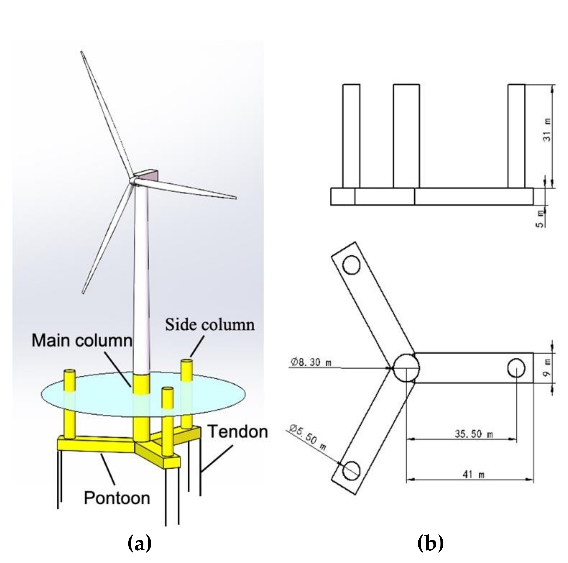
2.1. Physical Model Description

The floating platform with a taut mooring system was modified based on the CSC-Braceless semisubmersible prototype designed by Luan et al. [17]. The three catenary mooring lines were replaced by 6 tendons as shown in Figure 1a. The main dimensions of the platform are illustrated in Figure 1b. The designed water depth was reduced from 200 m to 60 m, which is more applicable in the China Sea and other areas with moderate depth. Other than the NREL 5-MW wind turbine used in Reference [19], the present study aims to redesign the platform to support the IEA 10-MW offshore wind turbine prototype [20]. The properties of the wind turbine are listed in Table 1.
Based on the change of the water depth, mooring system, and wind turbine prototype, the dimensions of the platform were modified through several iterations to satisfy the design standards given in DNVGL-RP-0286 and DNVGL-OS-E301 [21,22]. As illustrated in Figure 1b, the platform consisted of a main column and three side columns connected by pontoons. The turbine was installed on the main column, with a freeboard of 10 m. The properties of the platform and mooring system are summarized in Table 2.

2.2. Numerical Modeling

The numerical model of the TLP FOWT was built using the fully coupled aero-hydro-servo-elastic-mooring simulation tool FAST [8]. The nonlinear time domain analysis of the coupled wind turbine and platform system is conducted based on Equation (1):
M i j q , u , t q ¨ j = f i q , q ˙ , u , t
where M i j is the (i, j) component of the inertia mass matrix. The factors that affect M i j are the set of system DOFs (q), control inputs (u), and time (t). Here, control inputs u refers to the input parameters related to the turbine control system, such as pitch and yaw control, TMD control, etc. q ¨ j represents the second time derivative of DOF j. The right-hand side of Equation (1) indicates that the forcing function, f i , nonlinearly depends on DOFs, q, and their first-time derivatives, q ˙ , control inputs, u , and time, t.
The external force acting on the FOWT system mainly comes from the aerodynamic loads acting on the wind turbine and the hydrodynamic loads acting on the platform. The theories used in the calculations are introduced as follows.

2.2.1. Aerodynamics

The aerodynamic loads on the turbine structure include steady aerodynamic forces generated by the mean speed, the periodic aerodynamic forces, and randomly fluctuating aerodynamic forces, which are calculated in the AeroDyn module within the FAST code [5]. The influence of the wake and the blade airfoil aerodynamics is calculated based on the Blade Element Momentum (BEM) theory. The effect of the tower on the blade is accounted in the AeroDyn module based on a combination of the potential flow and tower shadow models. The wind load on the tower is based on the tower diameter, drag coefficient, and local relative wind velocity. Once the properties of the blade and the tower are determined in the input file to the ElastoDyn and HydroDyn modules, the above-stated aerodynamic loads are calculated instantaneously and interfaced with the FAST main program at each time step as part of the aeroelastic calculations.
The stochastic wind simulator TurbSim is used to generate the 220-m × 220-m turbulent wind field based on the IEC Kaimal spectral model. The turbulence intensity corresponding to the wind speed was determined using the IEC Class C turbulence model in the simulation [23]. The wind shear exponent was selected to be 0.1, which is a typical value for offshore applications [24].

2.2.2. Hydrodynamics

The total external force acting on the floating platform includes the hydrodynamic- and hydrostatic-induced loads and the effects of the mooring dynamics, which are calculated by the equation
F i P l a t f o r m t = A i j ω q ¨ j + R e A X i ω , β e j ω t C i j L i n e s + C i j H y d r o s t a t i c q j B i j ω q ˙ j
where A is the amplitude of a regular incident wave of frequency ω and direction β; C i j L i n e s is the (i, j) component of the linear restoring matrix from all mooring lines, which is derived by the quasistatic mooring line analysis program MAP integrated in the FAST code [25]; and A i j ω , B i j ω , and C i j H y d r o s t a t i c are the frequency-dependent (i, j) components of the hydrodynamic-added mass and damping matrices and hydrostatic matrix obtained from the hydrodynamic analysis tool ANSYS AQWA [26]. Re denotes the real value of the argument, X i is the wave excitation force normalized per unit wave amplitude, which is also calculated in ANSYS AQWA, and e j ω t is the harmonic exponential [27]. The hydrodynamic coefficients output files from AQWA are transformed into WAMIT format and fed into the FAST main program.
The typical wave spectrum JONSWAP was used to determine the irregular wave conditions in the HydroDyn input file, which can be described by the following equation given by IEC 61400-3:
S ω = 1 2 π 5 16 H s 2 T p ω T p 2 π 5 e x p 5 4 ω T p 2 π 4 1 0.287   ln γ γ e x p 0.5 ω T p 2 π 1 σ ω 2
where HS is the significant wave height, Tp is the spectral peak period, γ is the peak enhancement parameter of a given irregular sea states, and σ is a scaling factor. The wave spectrum is transformed into the time domain by the inverse Fast Fourier Transform (IFFT) function in HydroDyn and utilized for the calculation of the wave kinematics.

2.2.3. Mooring Dynamics

The Mooring Analysis Program (MAP) is used in parallel with the FAST main program to model the forces on the mooring system, including elasticity, weight, and geometric nonlinearities based on a multisegmented, quasistatic (MSQS) theory, while the forces arising from inertia, viscous drag, internal damping, bending, and torsion are neglected [28]. This approach has been utilized in several previous studies on TLP FOWT [5,12,29] and proven to be sufficient in predicting the platform motions and loads for those equipped with taut mooring systems [30]. In the present study, each mooring line is represented by two nodes (fairlead and anchor) and an element. Since the taut mooring lines do not interact with the seabed, the relationship between the horizontal and vertical fairlead displacement and forces can simply be solved based on the following equations:
l = H W sinh 1 V H sinh 1 V W L H + H L E A
h = H W 1 + V H 2 1 + V W L H 2 + 1 E A   V L W L 2 2
where l and h are the horizontal and vertical fairlead displacements, H and V are the horizontal and vertical forces at the fairlead, W is the weight of the cable per unit length, L is the unstretched cable length, and EA is the axial stiffness of the mooring line.

3. Results and Discussions

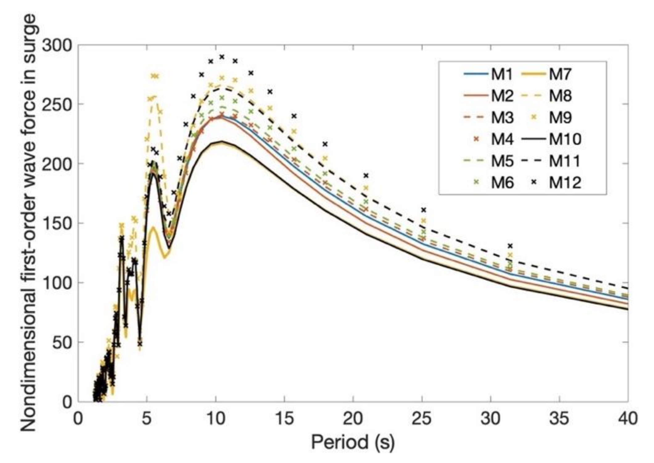
3.1. Hydrodynamic Analysis of Floating Platform

The hydrodynamic analysis of the floating platform is conducted using the software ANSYS AQWA to obtain the added mass coefficients, damping coefficients, and wave forces on the platform. In the present study, a comparison of the hydrodynamic performance of the platform between different combinations of dimensions was carried out after the preliminary conceptual design.
A total of 12 models with different drafts of platforms, widths, and heights of pontoons and diameters of side columns (as summarized in Table 3) were taken into consideration to select the one that had the least response to the waves. Since TLPs have relatively small responses in the vertical direction, whereas the horizontal motion is more sensitive to the excitation of waves, the first-order wave force along the surge direction was taken as the criterion for the selection. As illustrated in Figure 2, model M7, which had the smallest side column diameter, experienced the lowest wave force among all 12 models. Therefore, M7 was selected to be used in the following coupled analysis.

3.2. Coupled Analysis of FOWT

The coupled simulations are run using FAST to analyze the performance of the FOWT under multiple conditions.

3.2.1. Free-Decay Tests

Free-decay tests are conducted without wind and waves induced to obtain the natural periods of the platform. The free-decay curves in the surge, heave, pitch, and yaw are illustrated in Figure 3. Due to the symmetry of the platform, the results for sway and roll were identical to that of surge and pitch, which are not presented here.
The natural periods of the platform derived based on the free-decay curves, as well as the recommended value given by DNV-RP-0286 [21], are summarized in Table 4. It was found that the natural period of the platform in all six DOFs satisfied the standard.

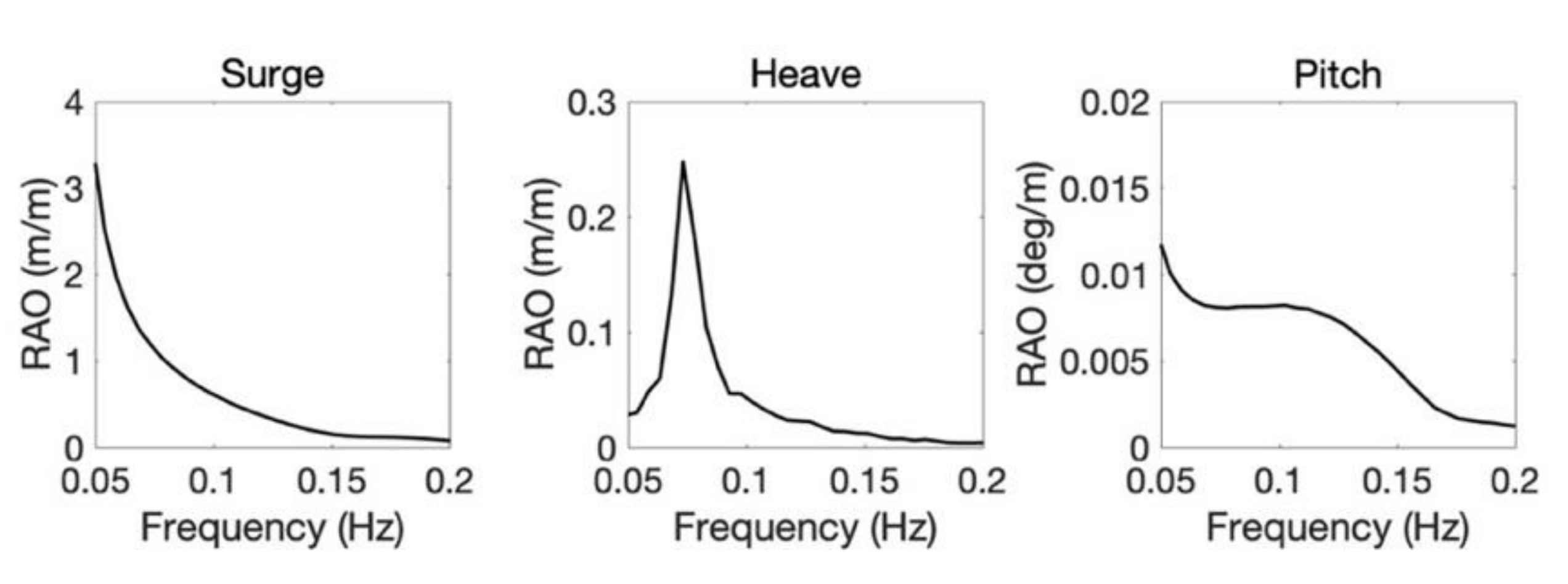
3.2.2. Response Amplitude Operators

The Response Amplitude Operators (RAOs) of the platform were derived using the method introduced by Ramachandran et al. [31]. The detailed calculation process is described as follows. The time domain simulation is run in FAST without wind inflow for a time duration of 8000 s. The FOWT is excited by white noise waves with a wave height of 2 m. The bandwidth of the input waves ranges from 0.1 rad/s to 6.28 rad/s to cover the eigen frequency of the platform in all DOFs. The time domain responses and wave time histories are performed by excluding the transients of the first 2000 s, and the rest of the data are transformed into the frequency domain spectrum using the Fast Fourier Transform function in MATLAB, and the RAOs are calculated based on the following equation:
R A O i = S i S W a v e
where i is the mode associated with the platform DOF, and Si and SWave are the spectral response in the i th mode and wave, respectively. For each DOF, the results were obtained by averaging the three computations.
The RAOs of the braceless platform in surge, heave, and pitch within the typical wave frequency range are shown in Figure 4. As illustrated by the figure, the surge response is much more significant than that in heave and pitch, especially at a low frequency. The maximum RAO reaches 3.5 m/m at the frequency of 0.05 s. The peak of the platform heave RAO was found at the corresponding natural frequency, i.e., approximately 0.77 Hz, with the value of 0.26 m/m. The response of the platform pitch remained below 0.015 degree/m between 0.05 Hz and 0.2 Hz.

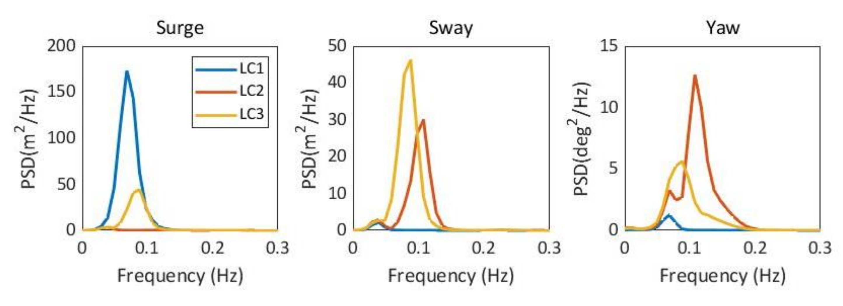
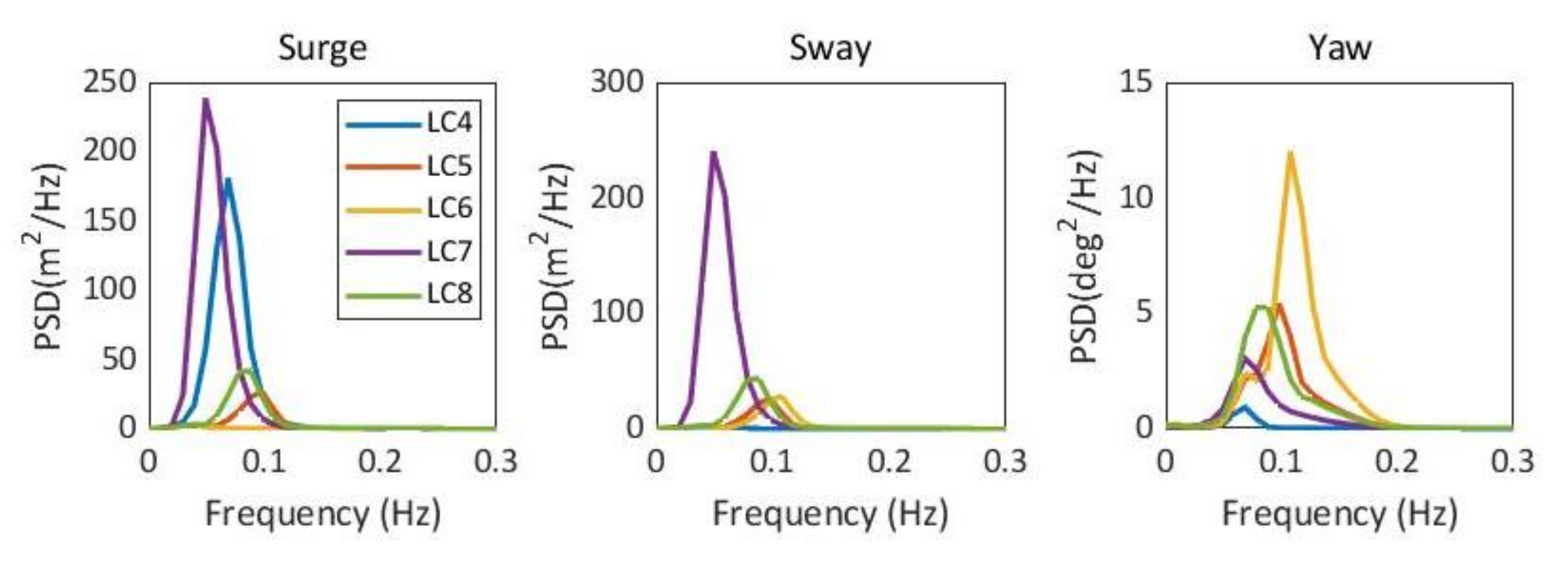
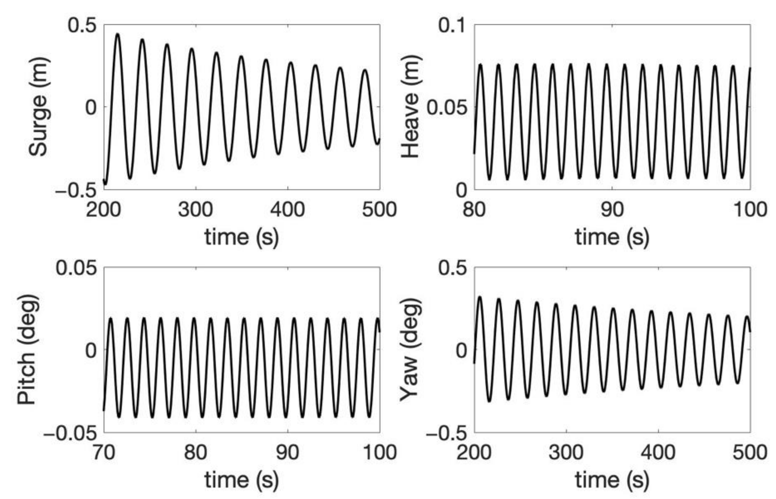
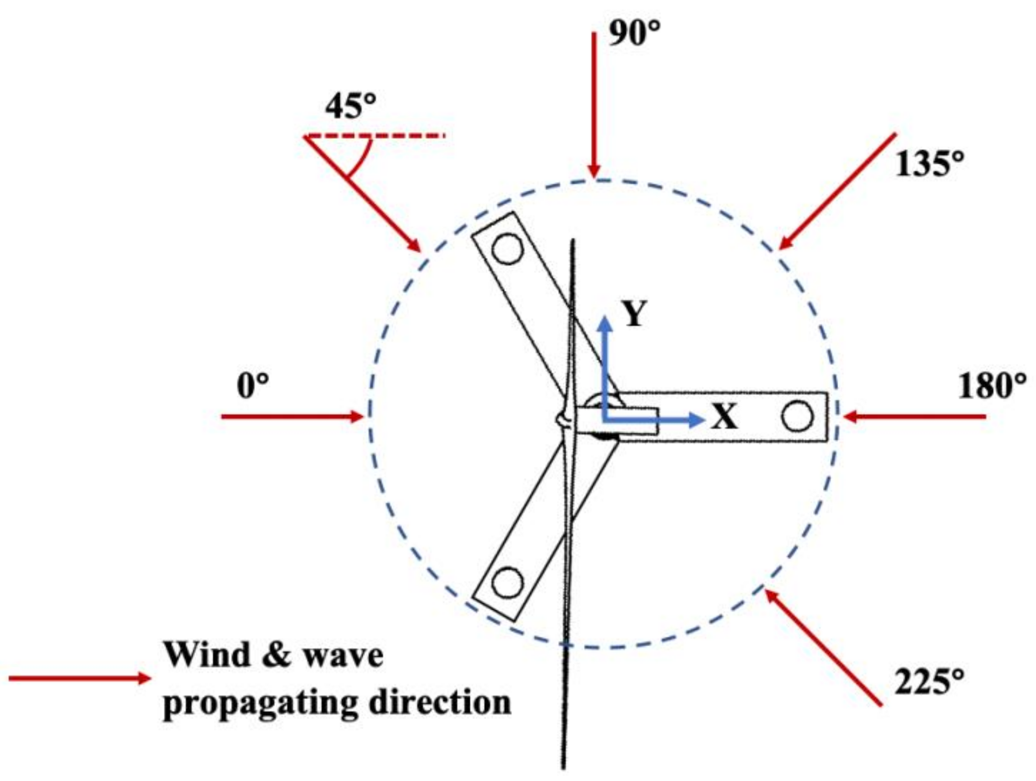
3.2.3. Responses to Wind–Wave Combined Effects

The performance of Braceless-TLP FOWT was evaluated under the multiple wind–wave combined environmental conditions. A total of 20 load cases were determined based on the wind and wave data measured at the target site close to Fujian Province, China provided by the Huaneng Clean Energy Research Institute. The parameters for the environmental conditions are listed in Table 5. As can be seen from Table 5, the wind and waves propagated along the direction ranges from 0° to 225° in different load cases. The directions were defined by the angle between the wind/wave inflow and the positive x-axis clockwise, as illustrated in Figure 5. The wind and waves were assumed to be collinear and turned together in all the cases, i.e., misalignment between wind and waves was not accounted for in the present study. For LC1–LC8, the turbine was set to be parked, and the blades were feathered to 90°, since the mean wind speed exceeded the cut-out speed. For LC9–LC20, the turbine was normally operated, and the nacelle was yawed to ensure the rotor plane facing the wind inflow direction, thus sufficiently capturing the energy. Each case was run for 4800 s, while the first 1200 s were removed to exclude the transient effect of the start.
The maximum, minimum, mean value, and standard deviation of the platform motions in six DOFs for the 20 load cases are shown in Figure 6. The results demonstrated that the FOWT can survive in the 100-year return extreme weather conditions. What stood out from the figure was that the largest platform responses in all the DOFs except for yaw were observed in LC7 (50-year return), where the significant wave height, peak period, and mean wind speed at the hub height were 8.69 m, 16.4 s, and 35.55 m/s, respectively, and the wind and waves propagated along the direction of 135°, as illustrated in Figure 5. The load case had the longest peak period of the wave among all the environmental conditions. The largest horizontal displacement (surge and sway) was 9.1 m (15% of a water depth of 60 m), which was smaller than the admissible offset to a depth ratio of 23%, as suggested in Reference [32]. For TLPs, as the platform was tightly restricted by the tendons along the vertical direction, the platform heave offset was normally related to the coupling with surge and sway. It could be seen that the largest heave motion occurred at LC7, as well. The pitch and roll motions remained below 1.5° in all the load cases, which effectively illustrated the stability of the TLP FOWT. The results suggested that the platform yaw angle was closely related to the direction of the wind and waves. For the 100- and 50-year-return load cases, the largest yaw motions were observed when the wind and waves were propagating along 90° (LC2 and LC6), while, for the 5- and 2-year-return load cases, the maximum values were found in the environment with an angle of 135° (LC12 and LC18).
Figure 7, Figure 8, Figure 9 and Figure 10 compare the power density spectrums (PSD) of the platform surge, sway, and yaw for the 100-, 50-, 5-, and 2-year-return load cases. It can be seen in Figure 7 that the energy content of the surge peaks at the wave frequency was highest when the loading was along the x-axis and rarely observed when the angle was 90°. The highest energy contents in surge and sway are seen in LC7 (Figure 8), where the largest corresponding responses are observed in Figure 6, as discussed above. As the environments became more moderate, the energy significantly reduced, as seen in Figure 9 and Figure 10.
The design guidelines pointed out that the tower top movements were expected to be in a similar order to those of the bottom fixed offshore wind turbine to ensure that the RNA was not heavily affected by the tensioned support structure. Figure 11 illustrates the fore–aft tower top displacements for LC9 and LC15 from 1200 s to 4800 of the simulation. The mean wind speeds of the two load cases were 20.77 m/s and 15.22 m/s along the direction of 0°. According to the results described in Reference [33], the fore–after tower top displacement for a monopile-type 10-MW DTU wind turbine at a wind speed of 16 m/s was within the range of approximately 0.3–0.9 m. The displacement calculated in the present study with a wind speed of 15.22 m/s was between −0.58 m and 0.59 m. The maximum and minimum tower top displacements calculated by Reference [33] when the wind speed was 20 m/s were about 0.1 m and 0.7 m, respectively, and the values in the present study were −0.91 to 0.65 m. Overall, the tower top displacement for the TLP FOWT had a slightly larger range than that with the fixed foundation but still in a similar order, indicating that the RNA was not significantly affected by the movement of the support platform during operation.
The statistics of the tension forces in the tendons are presented in Figure 12. The six tendons are numbered in a sequence anticlockwise from T1 to T6, as illustrated by the figure. The red dots denote the positions of tendon from plan view. The red dots denote the position of the fairleads from the top view. Since the tension forces in T1, T2, and T3 are identical to those in the corresponding adjacent tendons T4, T5, and T6, only the tensions of the former are shown in the figure. The largest tension force among the tendons was seen in T2 at LC7, which reached 14,923 kN. The mean tension forces were similar in all the load cases, while the maximum value varied and was closely related to the wind and wave directions. When the wind and waves spread along 0° and 180°, T1 experienced the largest tension among all the tendons. When the loading direction was 45°, T3 suffered from the largest tension force. For the cases with loading directions of 90° and 135°, the maximum values were seen in T2.
As suggested by DNV-RP-0286 [21], it is important to avoid tendon slack of the TLPs, especially for platforms that are installed in lower water levels. The minimum tension forces for the Braceless-TLP for all the load cases are summarized in Table 6. The data demonstrated that all the tendons remained taut during the 1-h simulation.

4. Conclusions

This study proposed a Braceless-TLP to support the IEA 10-MW offshore wind turbine aiming at a water depth of 60 m. The hydrodynamic analysis was conducted with 12 platform models with different combinations of dimensions using ANSYS AQWA software. The model suffered the lowest first-order wave excitation force selected and utilized in the coupled analysis with the wind turbine and mooring system. A fully coupled numerical analysis was carried out using the open-source program FAST. The free-decay tests, RAO analysis, and wind–wave combined analysis were presented to comprehensively investigate the dynamic characteristics of the platform and the performance of the FOWT under multiple environmental conditions.
The key findings are summarized as follows:
(1)
The natural periods of the platform in surge/way, heave, pitch/roll, and yaw were 26.4 s, 1.3 s, 2 s, and 19.7 s, which satisfied the standard given by DNV-RP-0268.
(2)
The RAOs of the platform were derived from the time series responses excited by white noise waves. The platform showed small RAO in heave and pitch, illustrating good stability of the structure in the corresponding DOFs.
(3)
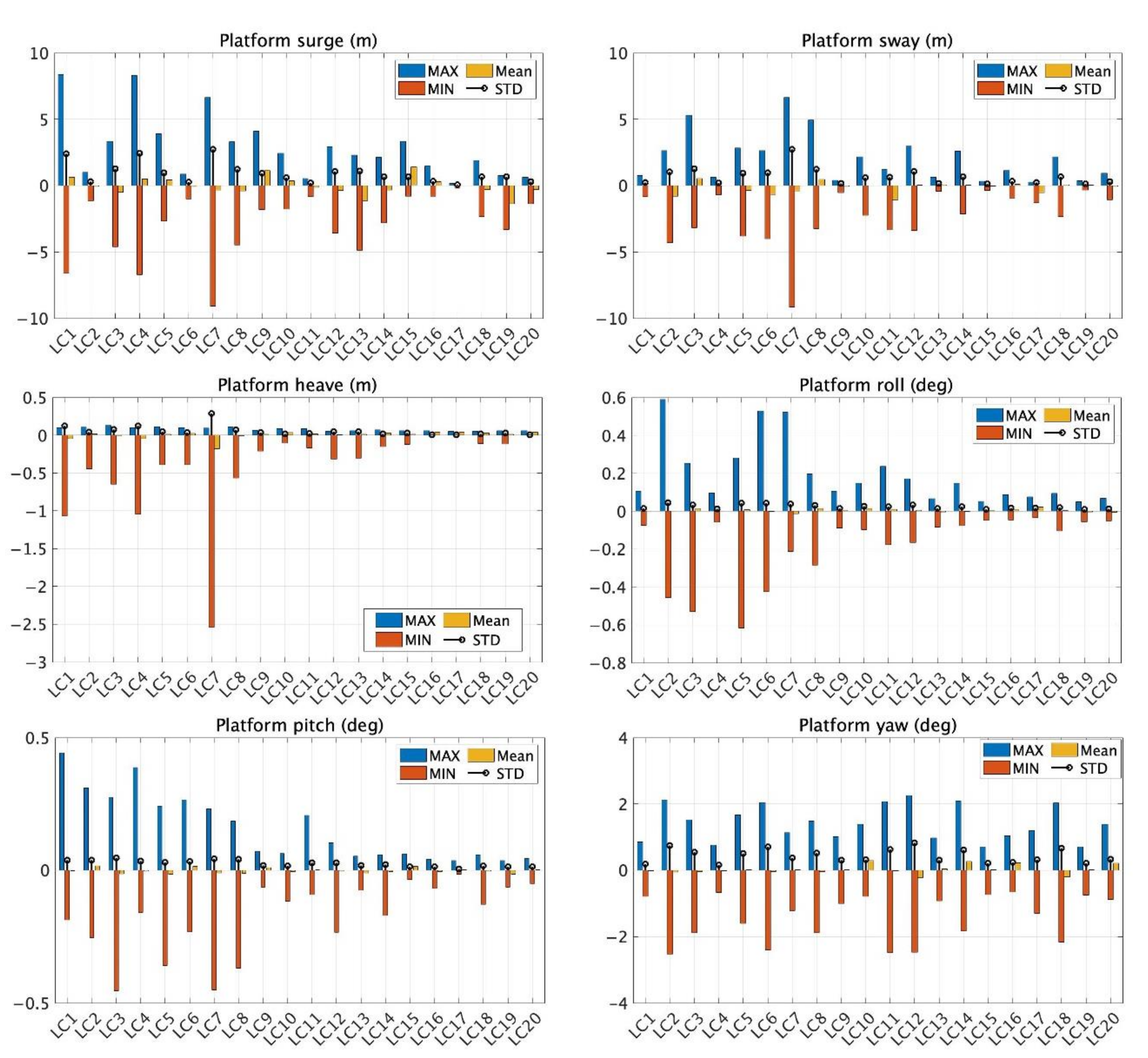
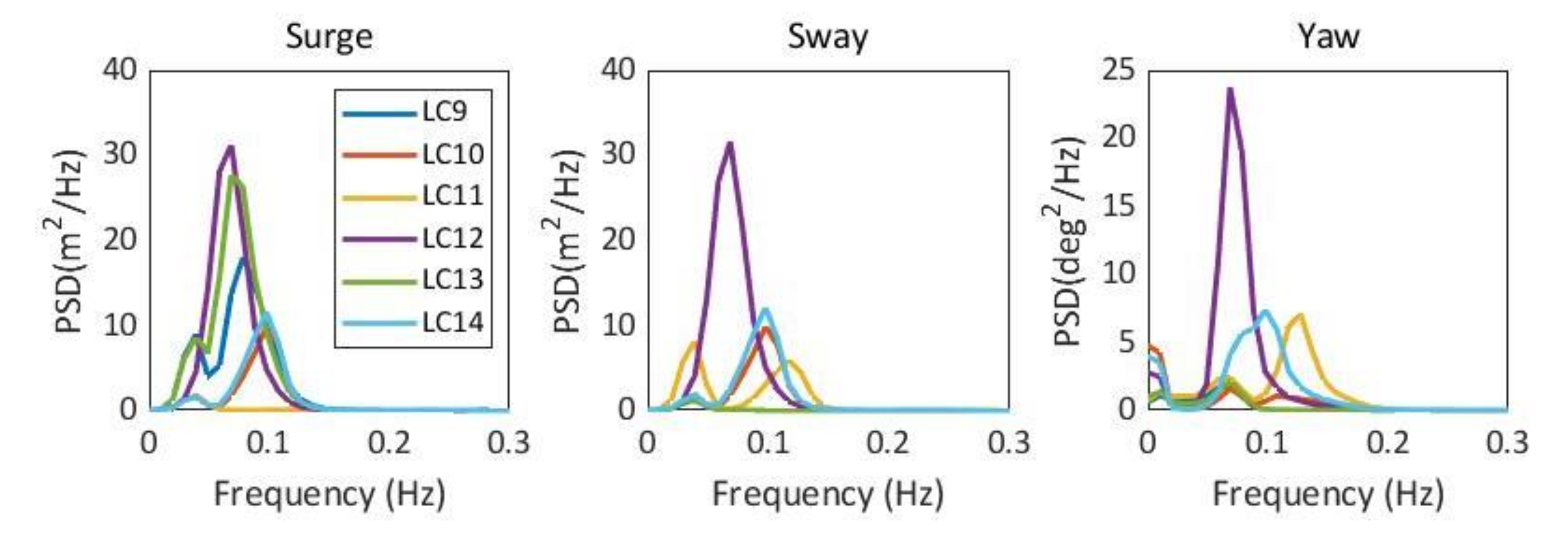
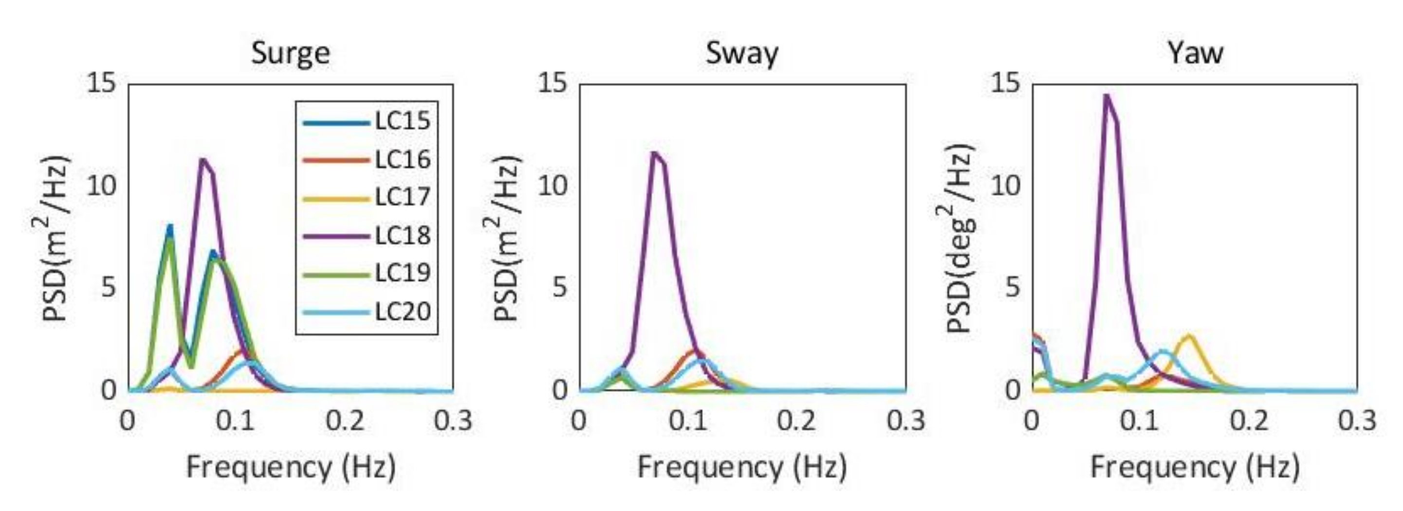
The effects of wind and waves on the responses of the FOWT were investigated. A total of 20 load cases were utilized combining different environmental parameters. The results showed that the FOWT can survive under the most extreme 100-year-return wind–wave combined environments.
(4)
The maximum surge displacement was 15% of the designed water depth, which was smaller than the admissible offset to the water depth ratio of 23%.
(5)
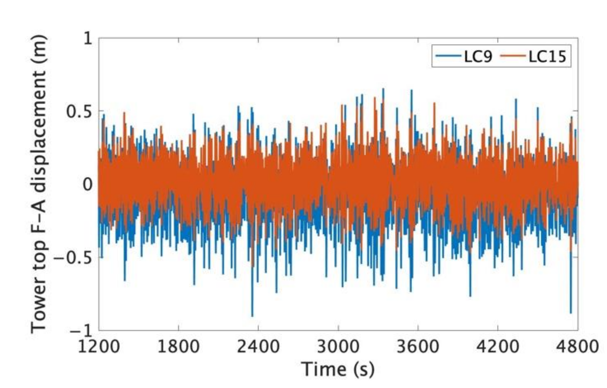
The tower top displacements were in the similar order as that calculated for a 10-MW wind turbine supported by the monopile foundation, indicating that the RNA was not affected by the motion of the floating platform.
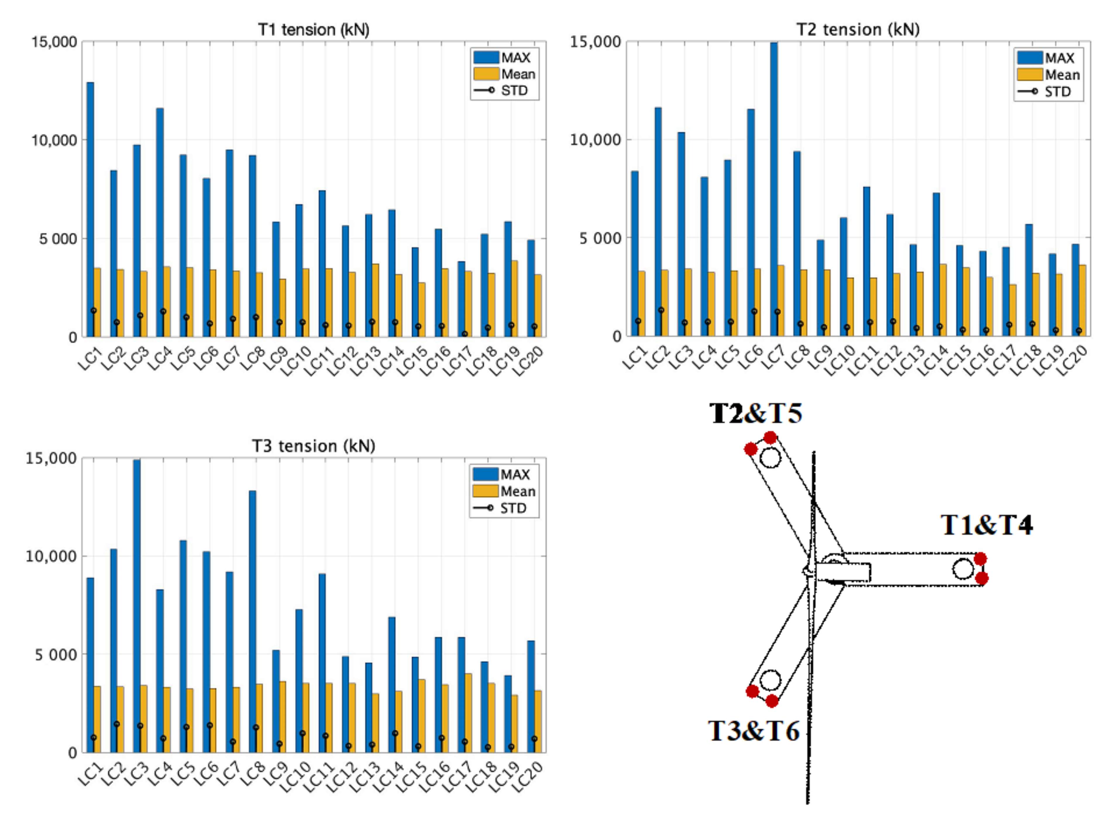
(6)
The largest tension force was 14,923 kN, which was observed in the 50-year-return load case. As the tendons experienced relatively high-tension forces, it was vital for TLP to select proper materials for station-keeping to avoid damage of the tendon due to the high-tension force. All six tendons remained tense during the simulation.
This study illustrated the feasibility of TLP FOWT to be installed in moderate water depths by a comprehensive numerical analysis. Experimental studies should be carried out in the future to validate and calibrate the numerical model. In addition, the designed prototype can be further optimized to reduce the wave loading on the platform and the tension force in the tendons to increase the reliability of the system.

Author Contributions

Conceptualization, Y.Z. and W.S.; methodology, Y.Z. and Y.R.; software, Y.R.; formal analysis, Y.R.; investigation, W.S. and X.L.; resources, Y.Z.; writing—original draft preparation, Y.Z. and Y.R.; and writing—review and editing, Y.Z., W.S. and X.L. All authors have read and agreed to the published version of the manuscript.

Funding

The work was supported by the China Huaneng Group Science and Technology Fund (HNKJ20-H53). This research was also partially funded by the National Natural Science Foundation of China (Grant No. 52071058 and 51939002). This work was also partially supported by; the Fundamental Research Funds for the Central Universities (DUT20ZD219), special funds for promoting high-quality development from the Department of Natural Resources of Guangdong Province (GDNRC (2020)016) and the Central Guidance on Local Science and Technology Development Fund of Shenzhen (2021Szvup018).

Institutional Review Board Statement

Not applicable.

Informed Consent Statement

Not applicable.

Data Availability Statement

Not applicable.

Conflicts of Interest

The authors declare no conflict of interest.

References

  1. Wang, Q. Design and Dynamic Analysis of a Steel Pontoon-Type Semi-Submersible Floater Supporting the DTU 10MW Reference Turbine. Master’s Thesis, Norwegian University of Science and Technology, Trondheim, Norway, 2014. [Google Scholar]
  2. Li, J.; Shi, W.; Zhang, L.; Michailides, C.; Li, X. Wind-Wave Coupling Effect on the Dynamic Response of a Combined Wind-Wave Energy Converter. J. Mar. Sci. Eng. 2021, 9, 1101. [Google Scholar] [CrossRef]
  3. GWEC. Global Offshore Wind Report 2021; GWEC: Brussels, Belgium, 2021. [Google Scholar]
  4. Wang, Y.; Shi, W.; Michailides, C.; Wan, L.; Kim, H.; Li, X. WEC shape effect on the motion response and power performance of a combined wind-wave energy converter. Ocean. Eng. 2022, accepted. [Google Scholar]
  5. Matha, D. Model Development and Loads Analysis of an Offshore Wind Turbine on a Tnesion Leg Platform, with a Comparison to Other Floating Turbine Concepts; National Renewable Energy Lab. (NREL): Golden, CO, USA, 2009. [Google Scholar]
  6. Speight, J.G. Subsea and Deepwater Oil and Gas Science and Technology; Gulf Professional Publishing: Oxford, UK, 2015. [Google Scholar]
  7. Withee, J.E. Fully Coupled Dynamic Analysis of a Floating Wind Turbine System. Ph.D. Thesis, Massachusetts Institute of Technology, Cambridge, MA, USA, 2004. [Google Scholar]
  8. Jonkman, J.M.; Buhl, M.L., Jr. FAST User’s Guide; NREL: Jefferson County, CO, USA, 2005. [Google Scholar]
  9. Vita, L.; Ramachandran, G.K.V.; Krieger, A.; Kvittem, M.I.; Merino, D.; Cross-Whiter, J.; Ackers, B.B. Comparison of Numerical Models and Verification Against Experimental Data, Using Pelastar TLP Concept. In Proceedings of the ASME 2015 34th International Conference on Ocean, Offshore and Arctic Engineering, St. John’s, NL, Canada, , 31 May–5 June 2015. [Google Scholar]
  10. Zhao, Y.; Yang, J.; He, Y. Preliminary Design of a Multi-Column TLP Foundation for a 5-MW Offshore Wind Turbine. Energies 2012, 5, 3874. [Google Scholar] [CrossRef]
  11. Zhao, Y.; She, X.; He, Y.; Yang, J.; Peng, T.; Kou, Y. Experimental Study on New Multi-Column Tension-Leg-Type Floating Wind Turbine. China Ocean. Eng. 2018, 32, 123–131. [Google Scholar] [CrossRef]
  12. Ding, H.; Han, Y.; Zhang, P.; Le, C.; Liu, J. Dynamic Analysis of a New Type of Floating Platform for Offshore Wind Turbine. In Proceedings of the the Twenty-Sixth (2016) International Ocean and Polar Engineering Conference, Rhodes, Greece, 26 June–1 July 2016. [Google Scholar]
  13. Oguz, E.; Day, A.H.; Clelland, D.; Incecik, A.; Dai, S.; Lopez, J.A.; González, G.; Sánchez, G.D. Experimental Study of a TLP Offshore Floating Wind Turbine. In Proceedings of the ICMT, Harbin, China, 16–18 July 2016. [Google Scholar]
  14. Ren, Y.; Vengatesan, V.; Shi, W. Dynamic Analysis of a Multi-column TLP Floating Offshore Wind Turbine with Tendon Failure Scenarios. Ocean Eng. 2022, 245, 110472. [Google Scholar] [CrossRef]
  15. Copple, R.; Capanoglu, C. Tension Leg Wind Turbine (TLWT) Conceptual Design Suitable for a Wide Range of Water Depths. In Proceedings of the the Twenty-Fourth International Ocean and Polar Engineering Conference, Busan, Korea, 15–20 June 2014. [Google Scholar]
  16. Zhao, Z.; Shi, W.; Wang, W.; Qi, S.; Li, X. Dynamic analysis of a novel semi-submersible platform for a 10 MW wind turbine in intermediate water depth. Ocean Eng. 2021, 237, 109688. [Google Scholar] [CrossRef]
  17. Luan, C.; Gao, Z.; Moan, T. Design and analysis of a braceless steel 5-MW semi-submersible wind turbine. In Proceedings of the 35th International Conference on Ocean, Offshore and Arctic Engineering, Busan, Korea, 19–24 June 2016. [Google Scholar]
  18. Peng, Z.; Zhao, H.; Li, X. New ductile fracture model for fracture prediction ranging from negative to high stress triaxiality. Int. J. Plast. 2021, 145, 103057. [Google Scholar] [CrossRef]
  19. Luan, C. Design and analysis for a steel braceless semi-submersible hull for supporting a 5-MW horizontal axis wind turbine. Ph.D. Thesis, Norwegian University of Science and Technology, Trondheim, Norway, 2018. [Google Scholar]
  20. Bortolotti, P.; Dykes, K.; Merz, K.; Zahle, F. IEA Wind Task 37 on Systems Engineering in Wind Energy. In WP2.1 Reference Wind Turbines; National Renewable Energy Laboratory: Golden, CO, USA, 2019. [Google Scholar]
  21. DNVGL. DNVGL-RP-0286 Coupled Analysis of Floating Wind Turbines; DNVGL: Bærum, Norway, 2019. [Google Scholar]
  22. DNVGL. DNVGL-OS-E301 Position Mooring; DNVGL: Bærum, Norway, 2015. [Google Scholar]
  23. Jonkman, J.; Buhl, J.M.L. TurbSim User’s Guide; NREL/TP-500-39797; National Renewable Energy Laboratory: Golden, CO, USA, 2006. [Google Scholar]
  24. Hsu, S.A.; Meindl, E.A.; Gilhousen, D.B. Determining the Power-Low Wind-Profile Exponent under Near-Neutral Stability Conditions at Sea. J. Appl. Meteorol. Climatol. 1994, 33, 757–765. [Google Scholar] [CrossRef] [Green Version]
  25. Masciola, M. MAP++ Documentation—Release 1.15; National Renewable Energy Laboratory: Golden, CO, USA, 2018. [Google Scholar]
  26. ANSYS, I.; ANSYS AQWA, Librium. NAUT and Tether Manuals. Electrical Source. Available online: https://cyberships.files.wordpress.com/2014/01/aqwa_ref.pdf (accessed on 15 October 2021).
  27. Jonkman, J.M. Dynamics Modeling and Loads Analysis of an Offshore Floating Wind Turbine. Ph.D. Thesis, National Renewable Energy Laboratory, Golden, CO, USA, 2007. [Google Scholar]
  28. Masciola, M.; Jonkman, J.; Robertson, A. Implementation of a Multisegmented, Quasi-Static Cable Model. In Proceedings of the International Ocean (Offshore) and Polar Engineering Conference, Anchorage, AK, USA, 30 June–5 July 2013. [Google Scholar]
  29. Wu, H.; Zhao, Y.; He, Y.; Shao, Y.; Mao, W.; Han, Z.; Huang, C.; Gu, X.; Jiang, Z. Transient response of a TLP-type floating offshore wind turbine under tendon failure conditions. Ocean Eng. 2021, 220, 108486. [Google Scholar] [CrossRef]
  30. Hall, M.; Buckham, B.; Crawford, C. Evaluating the importance of mooring line model fidelity in floating offshore wind turbine simulations. Wind Energy 2014, 17, 1835–1853. [Google Scholar] [CrossRef]
  31. Ramachandran, G.K.V.; Robertson, A.; Jonkman, J.M.; Masciola, M.D. Investigation of Response Amplitude Operators for Floating Offshore Wind Turbines. In Proceedings of the The 23rd International Ocean, Offshore and Polar Engineering Conference, Anchorage, AK, USA, 30 June–5 July 2013. [Google Scholar]
  32. Campanile, A.; Piscopo, V.; Scanardella, A. Mooring design and selection for floating offshore wind turbines on intermediate and deep water depths. Ocean. Eng. 2018, 148, 349–360. [Google Scholar] [CrossRef]
  33. Xi, R.; Du, X.; Wang, P.; Xu, C.; Zhai, E.; Wang, S. Dynamic analysis of 10 MW monopile supported offshore wind turbine based on fully coupled model. Ocean. Eng. 2021, 234, 109346. [Google Scholar] [CrossRef]
Figure 1. (a) Sketch of Braceless-TLP FOWT and (b) main dimensions (front and plan views).
Jmse 10 00302 g001
Figure 2. Comparison of nondimensional first-order wave forces along the surge direction for different platform models.
Jmse 10 00302 g002
Figure 3. Results of free-decay tests in surge, heave, pitch, and yaw.
Jmse 10 00302 g003
Figure 4. RAO of Braceless-TLP in surge, heave, and pitch.
Jmse 10 00302 g004
Figure 5. Illustration of the wind and wave propagating direction.
Jmse 10 00302 g005
Figure 6. Statistics of the platform motions (surge, sway, heave, roll, pitch, and yaw).
Jmse 10 00302 g006
Figure 7. PSD of the platform surge, sway, and yaw for the 100-year-return load cases (LC1–LC3).
Jmse 10 00302 g007
Figure 8. PSD of the platform surge, sway, and yaw for the 50-year-return load cases (LC4–LC8).
Jmse 10 00302 g008
Figure 9. PSD of the platform surge, sway, and yaw for the 5-year-return load cases (LC9–LC14).
Jmse 10 00302 g009
Figure 10. PSD of the platform surge, sway, and yaw for the 2-year-return load cases (LC15–LC20).
Jmse 10 00302 g010
Figure 11. Tower top fore–aft displacement.
Jmse 10 00302 g011
Figure 12. Statistics of the tension forces for tendons T1, T2, and T3.
Jmse 10 00302 g012
Table 1. Properties of IEA 10-MW offshore wind turbine.
ParameterValue
Wind RegimeIEC class 1A
Cut-in wind speed4 m/s
Cut-out wind speed25 m/s
Rated wind speed11 m/s
Rotor diameter198.0 m
Hub diameter4.6 m
Hub Height119 m
Minimum rotor speed6.0 rpm
Maximum rotor speed8.68 rpm
Maximum tip speed90.0 m/s
Hub overhang7.1 m
Shaft tilt angle6.0 deg.
Blade Mass47,700 kg
Nacelle mass542,600 kg
Tower mass628,442 kg
Table 2. Properties of floating platform and mooring system.
DimensionValue
Pontoon length36.4 m
Pontoon width9 m
Pontoon height5 m
Main column diameter8.3 m
Main column height36 m
Freeboard height10 m
Side column diameter5.5 m
Side column height41 m
Hull thickness0.015 m
Draft26 m
Platform mass (including ballast)4047 ton
Platform center of mass below SWL9.29 m
Platform pitch/roll moment of inertia1.65 × 109 kg m2
Platform yaw moment of inertia3.02 × 109 kg m2
Displacement7328 ton
Unstretched tendon length33.98 m
Tendon dry weight116.027 kg/m
Tendon axial stiffness1.8 × 109 N
Table 3. Dimensions of different models of platforms (unit: m).
PrototypeDraftPontoon WidthPontoon HeightColumn Diameter
M126956.5
M224956.5
M328956.5
M430956.5
M5261056.5
M6261156.5
M726955.5
M826957.5
M926958.5
M1026946.5
M1126966.5
M1226976.5
Table 4. Natural periods of a braceless platform.
ModePeriod (s)Standard (s)
Surge/sway26.415–60
Heave1.31–2
Roll/pitch22–5
Yaw19.78–20
Table 5. Parameters of the wind–wave combined load cases.
Load CaseReturn Period (Year)HS (m)TP (s)VHub (m/s)Direction (°)
LC11009.0713.338.130
LC28.459.344.1890
LC39.3811.441.45225
LC4508.9613.534.160
LC58.4510.436.7845
LC68.139.340.0590
LC78.6916.435.55135
LC89.0711.537.79225
LC955.1011.120.770
LC106.219.824.9245
LC115.948.224.9690
LC125.4713.623.37135
LC134.9912.220.15180
LC146.421024.82225
LC1523.5010.815.220
LC164.228.719.1745
LC173.68717.490
LC184.3412.218.76135
LC193.8110.415.64180
LC204.118.318.79225
Table 6. Minimum tension forces in T1, T2, and T3 (unit: kN).
Tendon
Load Case
T1T2T3
LC132.7937.1035.83
LC232.5032.3232.00
LC332.2932.4332.39
LC434.6345.1349.09
LC532.3032.6631.67
LC645.5232.3532.01
LC732.3232.8932.87
LC832.3142.7332.96
LC9435.781467.051990.44
LC1032.8772.3632.50
LC1134.8032.7632.43
LC121266.67550.782025.45
LC13845.871728.301637.50
LC1443.72761.6932.96
LC15919.792272.052577.92
LC161307.901853.66287.31
LC172686.97798.932222.04
LC181461.90956.232372.19
LC191673.042068.801745.74
LC201265.522071.74408.51
Publisher’s Note: MDPI stays neutral with regard to jurisdictional claims in published maps and institutional affiliations.

