Vibration Propagation on the Skin of the Arm


Abstract
1. Introduction
2. Materials and Methods
2.1. Participants
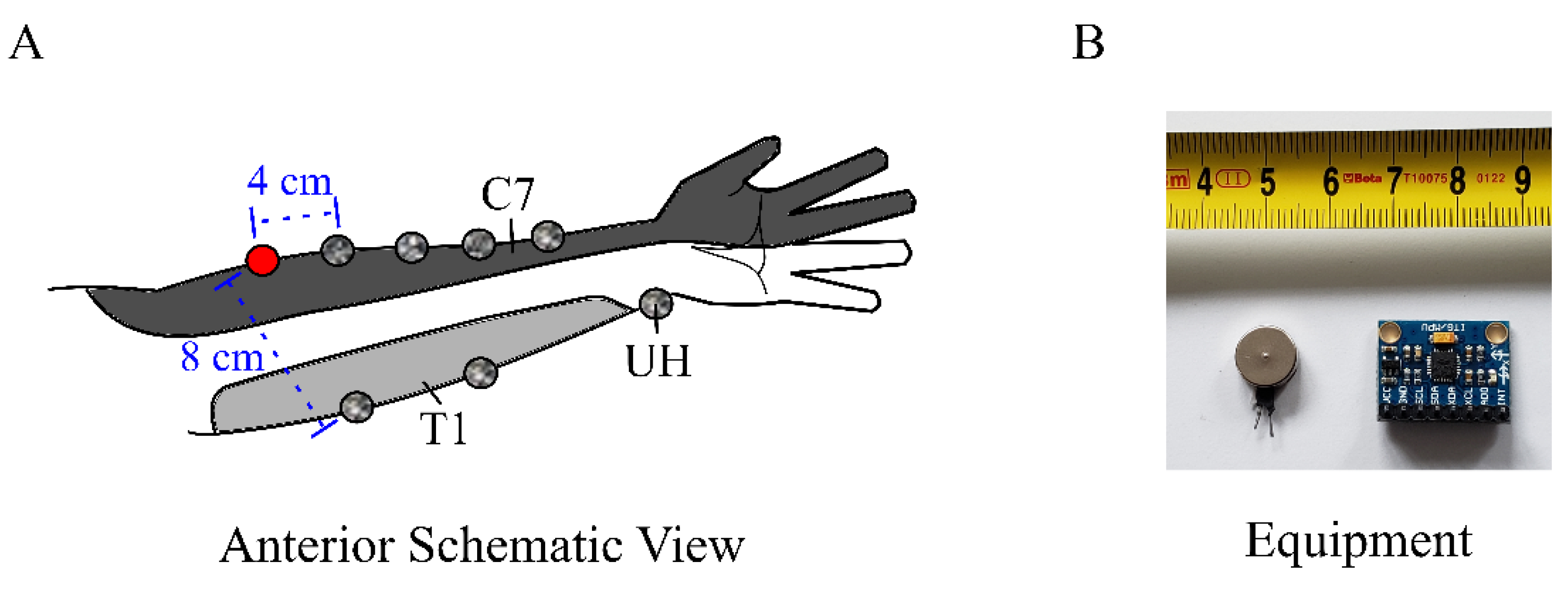
2.2. General Setup
2.3. Vibration Propagation Measurement
2.4. Vibration Stimuli
2.5. Data Analysis
2.6. Statistical Testing
3. Results
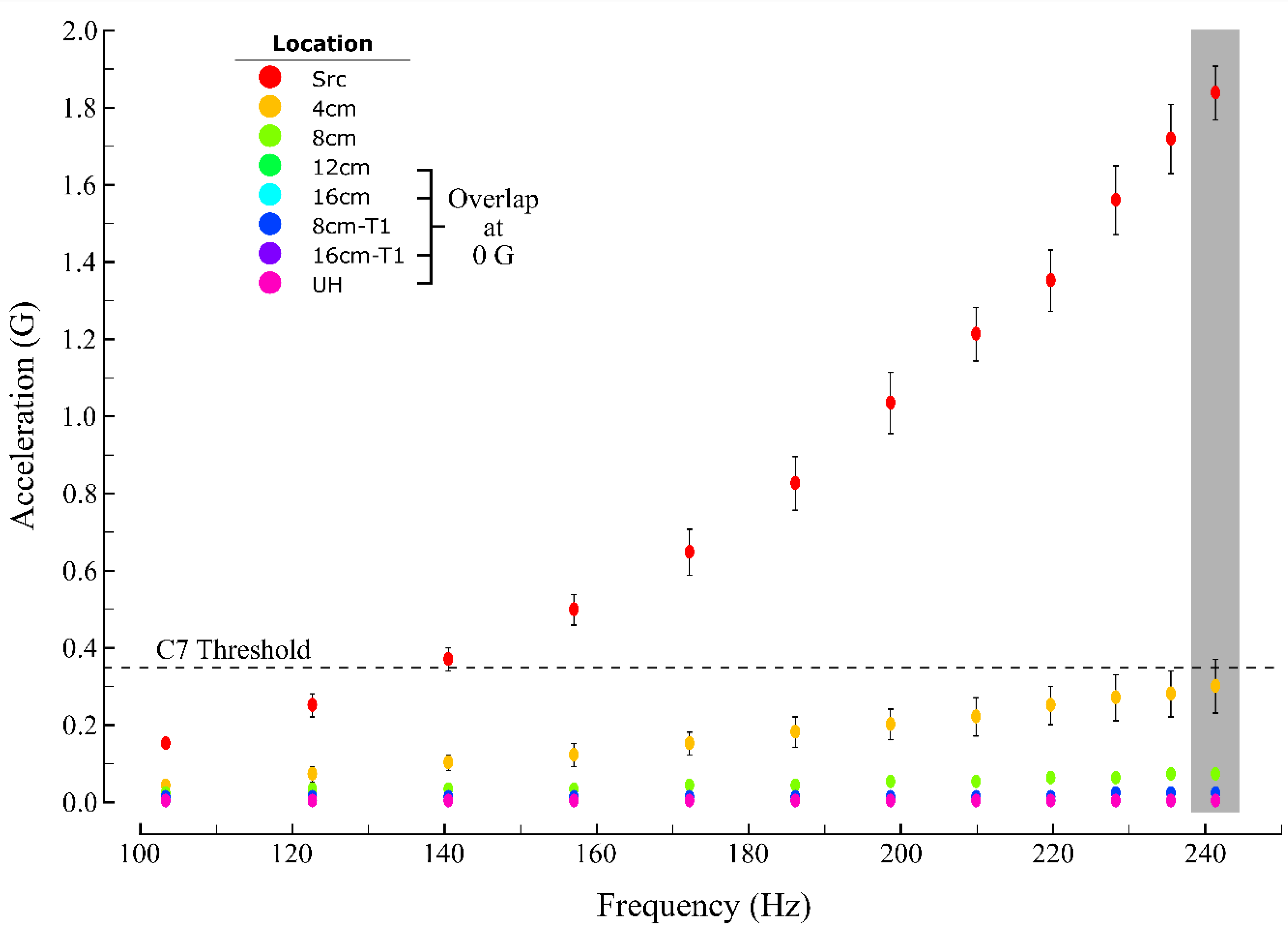
3.1. Measured Acceleration as a Function of Source Intensity and Distance
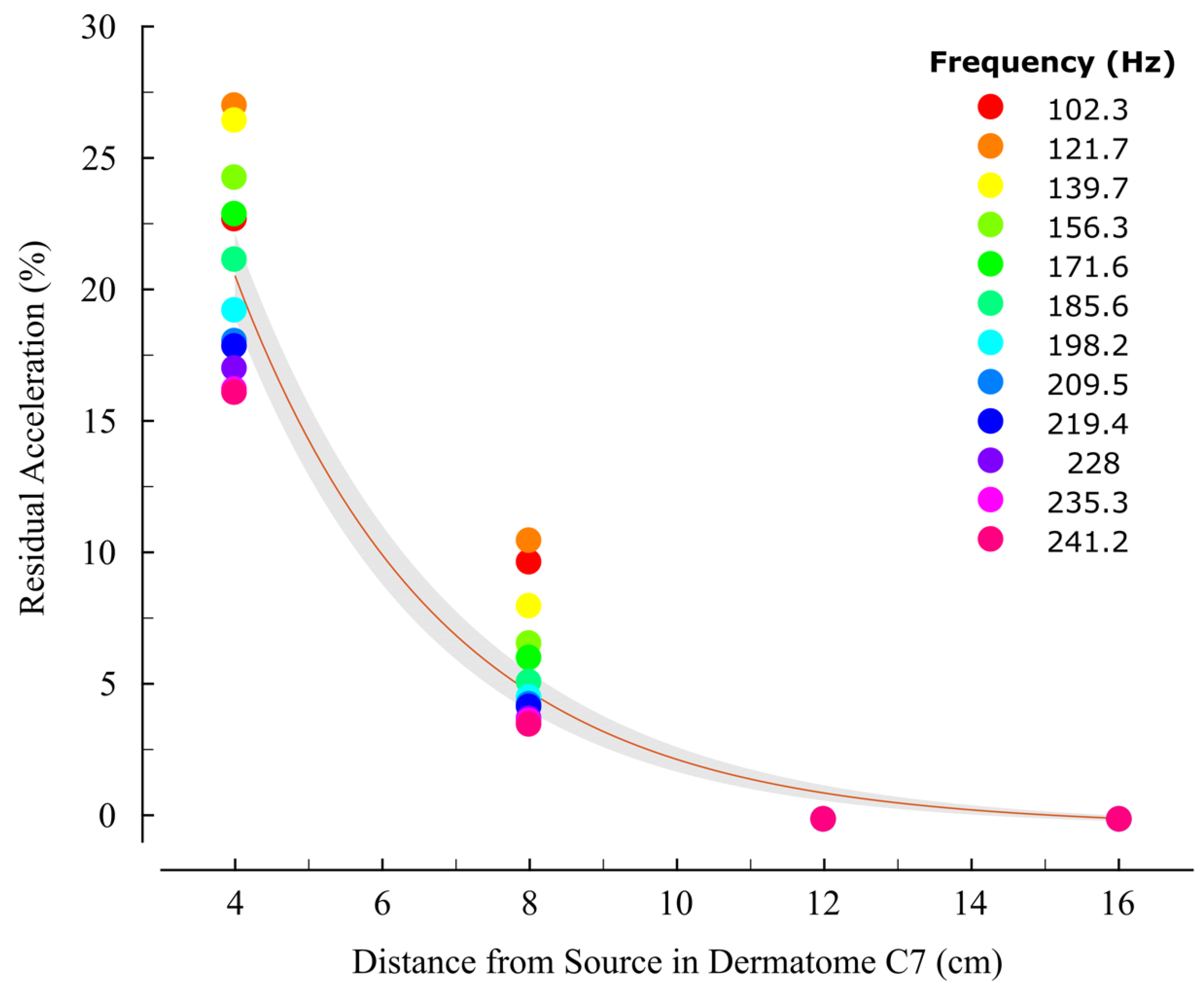
3.2. Acceleration Correlates with Distance
4. Discussion
4.1. Mechanisms of Perceptual Interference Between Stimulation Sites
4.2. Implications for Design of Vibrotactile Interfaces
4.3. Limitations
5. Conclusions
Author Contributions
Funding
Conflicts of Interest
Appendix A

| Bit Value (Bits) | 50 | 60 | 70 | 80 | 90 | 100 | 110 | 120 | 130 | 140 | 150 | 160 |
| Duty Cycle (%) | 19.7 | 23.6 | 27.6 | 31.5 | 35.4 | 39.4 | 43.3 | 47.2 | 51.2 | 55.1 | 59.1 | 63.0 |
| Input (V) | 0.98 | 1.18 | 1.37 | 1.57 | 1.77 | 1.96 | 2.16 | 2.36 | 2.55 | 2.75 | 2.95 | 3.15 |
| Freq (Hz) | 102.3 | 121.7 | 139.7 | 156.3 | 171.6 | 185.6 | 198.2 | 209.5 | 219.4 | 228.0 | 235.3 | 241.2 |
| Amp (G) | 0.45 | 0.65 | 0.85 | 1.05 | 1.20 | 1.40 | 1.55 | 1.75 | 1.90 | 2.15 | 2.25 | 2.35 |
| Subject | Age (yrs) | Height (cm) | Weight (kg) | Sex | Arm length (cm) | Circumference (cm) | 2-TDT @ Source (cm) | ||||
|---|---|---|---|---|---|---|---|---|---|---|---|
| Source | @ 4cm | @ 8cm | @ 12cm | @ 16cm | |||||||
| 1 | 21 | 178 | 83.9 | m | 26.70 | 27.90 | 27.90 | 26.60 | 24.10 | 20.30 | 3.50 |
| 2 | 18 | 185 | 70.3 | m | 27.90 | 26.70 | 26.00 | 26.00 | 23.20 | 19.40 | 3.75 |
| 3 | 31 | 157 | 68.0 | f | 21.60 | 25.40 | 25.40 | 24.10 | 20.30 | 17.80 | 3.50 |
| 4 | 42 | 157 | 52.2 | f | 22.90 | 22.20 | 22.20 | 21.00 | 17.80 | 15.60 | 2.50 |
| 5 | 23 | 164 | 45.5 | f | 24.40 | 19.90 | 18.60 | 17.30 | 15.20 | 13.60 | 4.50 |
| 6 | 62 | 157 | 72.6 | f | 21.60 | 25.10 | 24.80 | 21.00 | 17.80 | 15.90 | 3.75 |
| Ave | 32.83 | 166.33 | 65.42 | - | 24.18 | 24.53 | 24.15 | 22.67 | 19.73 | 17.10 | 3.58 |
| SD | 16.70 | 12.26 | 14.11 | - | 2.65 | 2.97 | 3.29 | 3.55 | 3.45 | 2.53 | 0.65 |
| Measurement Location (Dermatome) | ||||||||||
|---|---|---|---|---|---|---|---|---|---|---|
| Source (C7) | 4 cm (C7) | 8 cm (C7) | 12 cm (C7) | 16 cm (C7) | 8 cm (T1) | 16 cm (T1) | Ulnar head (C8) | |||
| Vibration Intensity (Hz) | 102.3 | 0.15 ± 0.01 | 0.04 ± 0.01 | 0.02 | 0.02 | 0.00 | 0.01 | 0.00 | 0.00 | Acceleration (G) |
| 121.7 | 0.25 ± 0.03 | 0.07 ± 0.02 | 0.03 ± 0.01 | 0.02 | 0.00 | 0.01 | 0.00 | 0.00 | ||
| 139.7 | 0.37 ± 0.03 | 0.10 ± 0.02 | 0.03 ± 0.01 | 0.02 | 0.00 | 0.01 | 0.00 | 0.00 | ||
| 156.3 | 0.50 ± 0.04 | 0.12 ± 0.03 | 0.03 ± 0.01 | 0.02 | 0.00 | 0.01 | 0.00 | 0.00 | ||
| 171.6 | 0.65 ± 0.06 | 0.15 ± 0.03 | 0.04 ± 0.01 | 0.02 | 0.00 | 0.01 | 0.00 | 0.00 | ||
| 185.6 | 0.83 ± 0.07 | 0.18 ± 0.04 | 0.04 ± 0.01 | 0.02 | 0.00 | 0.01 | 0.00 | 0.00 | ||
| 198.2 | 1.04 ± 0.08 | 0.20 ± 0.04 | 0.05 ± 0.01 | 0.02 | 0.00 | 0.01 | 0.00 | 0.00 | ||
| 209.5 | 1.22 ± 0.07 | 0.22 ± 0.05 | 0.05 ± 0.01 | 0.02 | 0.00 | 0.01 | 0.00 | 0.00 | ||
| 219.4 | 1.36 ± 0.08 | 0.25 ± 0.05 | 0.06 ± 0.01 | 0.02 | 0.00 | 0.01 | 0.00 | 0.00 | ||
| 228.0 | 1.57 ± 0.09 | 0.27 ± 0.06 | 0.06 ± 0.01 | 0.02 | 0.01 | 0.02 | 0.00 | 0.00 | ||
| 235.3 | 1.73 ± 0.09 | 0.28 ± 0.06 | 0.07 ± 0.01 | 0.02 | 0.00 | 0.02 | 0.00 | 0.00 | ||
| 241.2 | 1.85 ± 0.07 | 0.30 ± 0.07 | 0.07 ± 0.01 | 0.02 | 0.00 | 0.02 | 0.00 | 0.00 | ||
References
- Burgess, P. Cutaneous Mechanoreceptors. In Handbook of Perception; Carterette, E., Friedman, M., Eds.; Academic Press: New York, NY, USA, 1973; Volume 3, pp. 219–249. [Google Scholar]
- Hunt, C.C. The Pacinian Corpuscle. In The Peripheral Nervous System; Springer: Boston, MA, USA, 1974; pp. 405–420. [Google Scholar]
- Johansson, R.; Vallbo, A. Tactile sensibility in the human hand: Relative and absolute densities of four types of mechanoreceptive units in glabrous skin. J. Physiol. 1979, 286, 283–300. [Google Scholar] [CrossRef] [PubMed]
- Bolanowski, S.; Gescheider, G.; Verrillo, R.; Checkosky, C. Four channels mediate the mechanical aspects of touch. J. Acoust. Soc. Am. 1988, 84, 1680–1694. [Google Scholar] [CrossRef] [PubMed]
- Purves, D.; Augustine, G.; Fitzpatrick, D.; Hall, W.; LaMantia, A.; McNamara, J.; Williams, S. Neuroscience, 3rd ed.; Sinauer Associates Inc.: Sunderland, VT, USA, 2004. [Google Scholar]
- Casadio, M.; Ranganathan, R.; Mussa-Ivaldi, F. The Body-Machine Interface: A new perspective on an old theme. J. Mot. Behav. 2012, 44, 419–433. [Google Scholar] [CrossRef] [PubMed]
- Kaczmarek, K.; Webster, J.; Bach-y-Rita, P.; Tompkins, W. Electrotactile and Vibrotactile Displays for Sensory Substitution Systems. IEEE Trans. Biomed. Eng. 1991, 38, 1–16. [Google Scholar] [CrossRef] [PubMed]
- Sonar, H.; Paik, J. Soft Pneumatic Actuator Skin with Piezoelectric Sensors for Vibrotactile Feedback. Front. Rob. AI 2016, 2, 38. [Google Scholar] [CrossRef]
- Shull, P.; Darrian, D. Haptic wearables as sensory replacement, sensory augmentation and trainer—A review. J. Neuro-Eng. Rehabil. 2015, 12, 2–13. [Google Scholar] [CrossRef]
- Jones, L.; Sarter, N. Tactile Displays: Guidance for Their Design and Application. Hum. Factors 2008, 50, 90–111. [Google Scholar] [CrossRef]
- White, B.; Saunders, F.; Scadden, L.; Bach-Y-Rita, P.; Collins, C. Seeing with the skin. Percept. Psychophys. 1970, 7, 23–27. [Google Scholar] [CrossRef]
- Cincotti, F.; Kauhanen, L.; Aloise, F.; Palomaki, T.; Caporusso, N.; Jylanki, P.; Mattia, D.; Babiloni, F.; Vanacker, G.; Nuttin, M.; et al. Vibrotactile Feedback for Brain-Computer Interface Operation. Comput. Intell. Neurosci. 2007, 2007, 48937. [Google Scholar] [CrossRef][Green Version]
- Cipriani, C.; D’Alonzo, M.; Carrozza, M. A Miniature Vibrotactile Sensory Substitution Device for Multifingered Hand Prosthetics. IEEE Trans. Biomed. Eng. 2012, 59, 400–408. [Google Scholar] [CrossRef]
- Ariza, O.; Lange, M.; Steinicke, F.; Bruder, G. Vibrotactile Assistance for User Guidance Towards Selection Targets in VR and the Cognitive Resources Involved. In Proceedings of the 2017 IEEE Symposium on 3D User Interface, Los Angeles, CA, USA, 18–19 March 2017. [Google Scholar]
- Weber, B.; Schatzle, S.; Hulin, T.; Preusche, C.; Demi, B. Evaluation of a Vibrotactile Feedback Device for Spatial Guidance. In Proceedings of the 2011 IEEE World Haptics Conference, Istanbul, Turkey, 21–24 June 2011. [Google Scholar]
- Oakley, I.; Kim, Y.; Lee, J.; Ryu, J. Determining the Feasibility of Forearm Mounted Vibrotactile Displays. In Proceedings of the Symposium on Haptic Interfaces for Virtual Environment and Teleoperator Systems 2006, Alexandria, VA, USA, 25–26 March 2006. [Google Scholar]
- An, Q.; Matsuoka, Y.; Step, C. Multi-day Training with Vibrotactile Feedback for Virtual Object Manipulation. In Proceedings of the 2011 IEEE International Conference on Rehabilitation Robotics (ICORR), Zurich, Switzerland, 29 June–1 July 2011. [Google Scholar]
- Krueger, A.; Giannoni, P.; Shah, V.; Casadio, M.; Scheidt, R. Supplemental vibrotactile feedback control of stabilization and reaching actions of the arm using limb state and position error encodings. J. Neuroeng. Rehabil. 2017, 14, 36. [Google Scholar] [CrossRef] [PubMed]
- Caldwell, D.; Tsagarakis, N.; Giesler, C. An integrated tactile/shear feedback array for stimulation of finger mechanoreceptor. In Proceedings of the 1999 IEEE International Conference on Robotics and Automation, Detroit, MI, USA, 10–15 May 1999. [Google Scholar]
- Casini, S.; Morvidoni, M.; Bianchi, M.; Catalano, M.; Grioli, G.; Bicchi, A. Design and realization of the cuff-clenching upper-limb force feedback wearable device for distributed mechano-tactile stimulation of normal and tangential skin forces. In Proceedings of the 2015 IEEE/RSJ International Conference on Intelligent Robots and Systems (IROS), Hamburg, Germany, 28 September–2 October 2015. [Google Scholar]
- Bark, K.; Wheeler, J.; Lee, G.; Savall, J.; Cutkosky, M. A wearable skin stretch device for haptic feedback. In Proceedings of theWorld Haptics 2009-Third Joint EuroHaptics Conference and Symposium on Haptic Interfaces for Virtual Environment and Teleoperator Systems, Salt Lake City, UT, USA, 18–20 March 2009. [Google Scholar]
- Hayward, V.; Cruz-Hernandez, J. Tactile display device using distributed lateral skin stretch. In Proceedings of the Haptic Interfaces for Virtual Environment and Teleoperator Systems Symposium, New York, NY, USA, 5–10 November 2000. [Google Scholar]
- Schorr, S.; Quek, Z.; Romano, R.; Nisky, I.; Provancher, W.; Okamura, A. Sensory substitution via cutaneous skin stretch feedback. In Proceedings of the 2013 IEEE International Conference on Robotics and Automation, Karlsruhe, Germany, 6–10 May 2013. [Google Scholar]
- Ribot-Ciscar, E.; Vedel, J.; Roll, J. Vibration sensitivity of slowly and rapidly adapting cutaneous mechanoreceptors in the human foot and leg. Neurosci. Lett. 1989, 104, 130–135. [Google Scholar] [CrossRef]
- Mountcastle, V.; LaMotte, R.; Carli, G. Detection thresholds for stimuli in humans and monkeys: Comparison with threshold events in mechanoreceptive afferent nerve fibers innervating the monkey hand. J. Neurophysiol. 1972, 35, 122–136. [Google Scholar] [CrossRef] [PubMed]
- Perez, C.; Holzmann, C.; Jaeschke, H. Two-point vibrotactile discrimination related to parameters of pulse burst stimulus. Med. Biol. Eng. Comput. 2000, 38, 74–79. [Google Scholar] [CrossRef] [PubMed]
- Tannan, V.; Whitsel, B.; Tommerdahl, M. Vibrotactile adaptation enhances spatial localization. Brain Res. 2006, 1102, 109–116. [Google Scholar] [CrossRef]
- Cholewiak, R.; Collins, A. Vibrotactile localization on the arm: Effects of place, space and age. Percept. Psychophys. 2003, 65, 1058–1077. [Google Scholar] [CrossRef]
- Sofia, K.; Jones, L. Mechanical and Psychophysical Studies of Surface Wave Propagation during Vibrotactile Stimulation. IEEE Trans. Haptics 2013, 6, 320–329. [Google Scholar] [CrossRef]
- Precision Microdrives Limited. 10mm Vibration Motor—3 mm Type Model:310-117 Performance Specifications Dimensions. Available online: https://www.precisionmicrodrives.com/product/310-117-10mm-vibration-motor-3mm-type (accessed on 5 May 2019).
- InvenSense. MPU-6050 Six-Axis (Gyro + Accelerometer) MEMS MotionTracking™ Devices. Available online: https://www.invensense.com/products/motion-tracking/6-axis/mpu-6050/ (accessed on 5 May 2019).
- Shah, V.A.; Casadio, M.; Scheidt, R.A.; Mrotek, L.A. Spatial and Temporal Influences on Discrimination of Vibrotactile Stimuli on the Arm. Exp. Brain Res. 2019, 237, 2075–2086. [Google Scholar] [CrossRef]
- Jones, L.; Held, D. Characterization of tactors used in vibrotactile displays. J. Comput. Inf. Sci. Eng. 2008, 8, 044501. [Google Scholar] [CrossRef]
- Johnson, K.O. The roles and functions of cutaneous mechanoreceptors. Curr. Opin. Neurobiol. 2001, 11, 455–461. [Google Scholar] [CrossRef]
- Muniak, M.A.; Ray, S.; Hsiao, S.S.; Dammann, J.F.; Bensmaia, S.J. The Neural Coding of Stimulus Intensity: Linking the Population Response of Mechanoreceptive Afferents with Psychophysical Behavior. J. Neurosci. 2007, 27, 11687–11699. [Google Scholar] [CrossRef] [PubMed]
- Manfredi, L.; Baker, A.; Elias, D.; Dammann, J., III; Zielinski, M.; Polashock, V.; Bensmaia, S. The Effect of Surface Wave Propagation on Neural Responses to Vibration in Primate Glabrous Skin. PLoS ONE 2012, 7, e31203. [Google Scholar] [CrossRef] [PubMed]
- Ferris, T.; Sarter, N. Continuously Informing Vibrotactile Displays in Support of Attention Management and Multitasking in Anesthesiology. Hum. Factors 2011, 53, 600–611. [Google Scholar] [CrossRef] [PubMed]
- Liebermann, J.; Breazeal, C. TIKL: Development of a Wearable Vibrotactile Feedback Suit for Improved Human Motor Learning. IEEE Trans. Robot. 2007, 23, 919–926. [Google Scholar] [CrossRef]
- Wang, F.; Zhang, W.; Luo, W. An Empirical Evaluation on Vibrotactile Feedback for Wristband System. Mob. Inf. Syst. 2018, 4878014. [Google Scholar] [CrossRef]
- Piateski, E.; Jones, L. Vibrotactile pattern recognition on the arm and torso. In Proceedings of the Proceedings of the first joint Eurohaptics Conference and Symposium on Haptic Interfaces for Virtual Environment and Teleoperator Systems, Pisa, Italy, 18–20 March 2005. [Google Scholar]
- Nolan, M. Two-Point Discrimination Assessment in the Upper Limb in Young Adult Men and Women. Phys. Ther. 1982, 62, 965–969. [Google Scholar] [CrossRef]
- Cashin, A.G.; McAuley, J.H. Measuring two-point discrimination threshold with a caliper. J. Physiother. 2017, 63, 186. [Google Scholar] [CrossRef]
- Risi, N.; Shah, V.; Mrotek, L.A.; Casadio, M.; Scheidt, R.A. Supplemental vibrotactile feedback of real-time limb position enhances precision of goal-directed reaching. J. Neurophysiol. 2019, 122, 22–38. [Google Scholar] [CrossRef]
- Shah, V.A.; Risi, N.; Ballardini, G.; Mrotek, L.A.; Casadio, M.; Scheidt, R.A. Effect of Dual Tasking on Vibrotactile Feedback Guided Reaching—A Pilot Study. In Haptics: Science, Technology, and Applications; EuroHaptics 2018. Lecture Notes in Computer Science, vol 10893; Springer: Cham, Switzerland, 2018; pp. 3–14. [Google Scholar]
- Tzorakoleftherakis, E.; Bengtson, M.C.; Mussa-Ivaldi, F.A.; Scheidt, R.A.; Murphey, T.D. Tactile proprioceptive input in robotic rehabilitation after stroke. In Proceedings of the 2015 IEEE International Conference on Robotics and Automation (ICRA), Seattle, WA, USA, 26–30 May 2015; pp. 6475–6481. [Google Scholar]


© 2019 by the authors. Licensee MDPI, Basel, Switzerland. This article is an open access article distributed under the terms and conditions of the Creative Commons Attribution (CC BY) license (http://creativecommons.org/licenses/by/4.0/).
Share and Cite
Shah, V.A.; Casadio, M.; Scheidt, R.A.; Mrotek, L.A. Vibration Propagation on the Skin of the Arm. Appl. Sci. 2019, 9, 4329. https://doi.org/10.3390/app9204329
Shah VA, Casadio M, Scheidt RA, Mrotek LA. Vibration Propagation on the Skin of the Arm. Applied Sciences. 2019; 9(20):4329. https://doi.org/10.3390/app9204329
Chicago/Turabian StyleShah, Valay A., Maura Casadio, Robert A. Scheidt, and Leigh A. Mrotek. 2019. "Vibration Propagation on the Skin of the Arm" Applied Sciences 9, no. 20: 4329. https://doi.org/10.3390/app9204329
APA StyleShah, V. A., Casadio, M., Scheidt, R. A., & Mrotek, L. A. (2019). Vibration Propagation on the Skin of the Arm. Applied Sciences, 9(20), 4329. https://doi.org/10.3390/app9204329