Article

Virtual Scene Construction for Seismic Damage of Building Ceilings and Furniture

1
Beijing Key Laboratory of Urban Underground Space Engineering, School of Civil and Resource Engineering, University of Science and Technology Beijing, Beijing 100083, China
2
Department of Civil Engineering, Tsinghua University, Beijing 100084, China
*
Author to whom correspondence should be addressed.
Appl. Sci. 2019, 9(17), 3465; https://doi.org/10.3390/app9173465
Submission received: 15 July 2019 / Revised: 19 August 2019 / Accepted: 19 August 2019 / Published: 22 August 2019
(This article belongs to the Special Issue Extreme Sciences and Engineering)

Abstract

:
A valid seismic damage scene for indoor nonstructural components is critical for virtual earthquake safety drills which can teach occupants how to survive in earthquakes. A virtual scene construction method for the seismic damage of suspended ceilings and moveable furniture is proposed based on FEMA P-58 and a physics engine. First, a modeling framework is designed based on building information modeling (BIM) to create consistent structural and scene models for the subsequent structural time-history analysis (THA) and scene construction. Subsequently, FEMA P-58 is employed to determine the damage states of nonstructural components based on the results of the THA. Finally, the physical models on the movements of the damaged components are designed using a physics engine and are also validated through the experiments such as an existing shaking table test. Considering a six-story building as a case study, a virtual earthquake scene of the indoor nonstructural components is constructed and applied in an earthquake safety drill. The outcome of this study provides well-founded scenes of the seismic damage to indoor nonstructural components for performing virtual earthquake safety drills.

Graphical Abstract

1. Introduction

With the development of earthquake engineering, the earthquake-induced collapse of building structures has been effectively controlled in recent years [1,2,3,4,5,6]. However, seismic damage of indoor nonstructural components remains a serious issue, leading to possible occupant casualties. For example, in the 2017 Jiuzhaigou Earthquake (Ms 7.0), most buildings did not suffer serious damage or collapse [7], and indoor nonstructural damage (e.g., fallen ceilings and overturned furniture) caused the majority of casualties [8].
Construction of a virtual seismic damage scene for indoor nonstructural components can be used to conduct virtual earthquake safety drills for occupants [9]. For instance, Tarnanas et al. [10] used virtual earthquake scene to teach special populations how to cope in emergency. Lovreglio et al. [11,12] proposed a virtual reality (VR) based drill tool for building earthquake preparedness, by which the indoor earthquake scene of the Auckland City Hospital, New Zealand was built and thus the virtual earthquake evacuation drill was performed. Such virtual drills can help occupants avoid physical injuries induced by nonstructural damage and thus decrease the number of casualties.
The validity of the virtual seismic damage scene for indoor nonstructural components is critical for virtual earthquake drills, because the unreasonable seismic damage scene may mislead occupants into making poor safety decisions in drills. However, the existing research has focused on realistic representation of indoor seismic damage rather than the validity of the seismic damage [10,11,12,13,14,15]. For instance, Li et al. [16] created realistic virtual scenes of the indoor seismic damage to nonstructural components. However, the ground motion was directly used to calculate the damage of nonstructural components, while the dynamic seismic response of the building structure was not considered, which will lead to a significant error in determining the damage of nonstructural components.
To construct a valid virtual seismic damage scene for indoor nonstructural components, three important problems must be resolved:
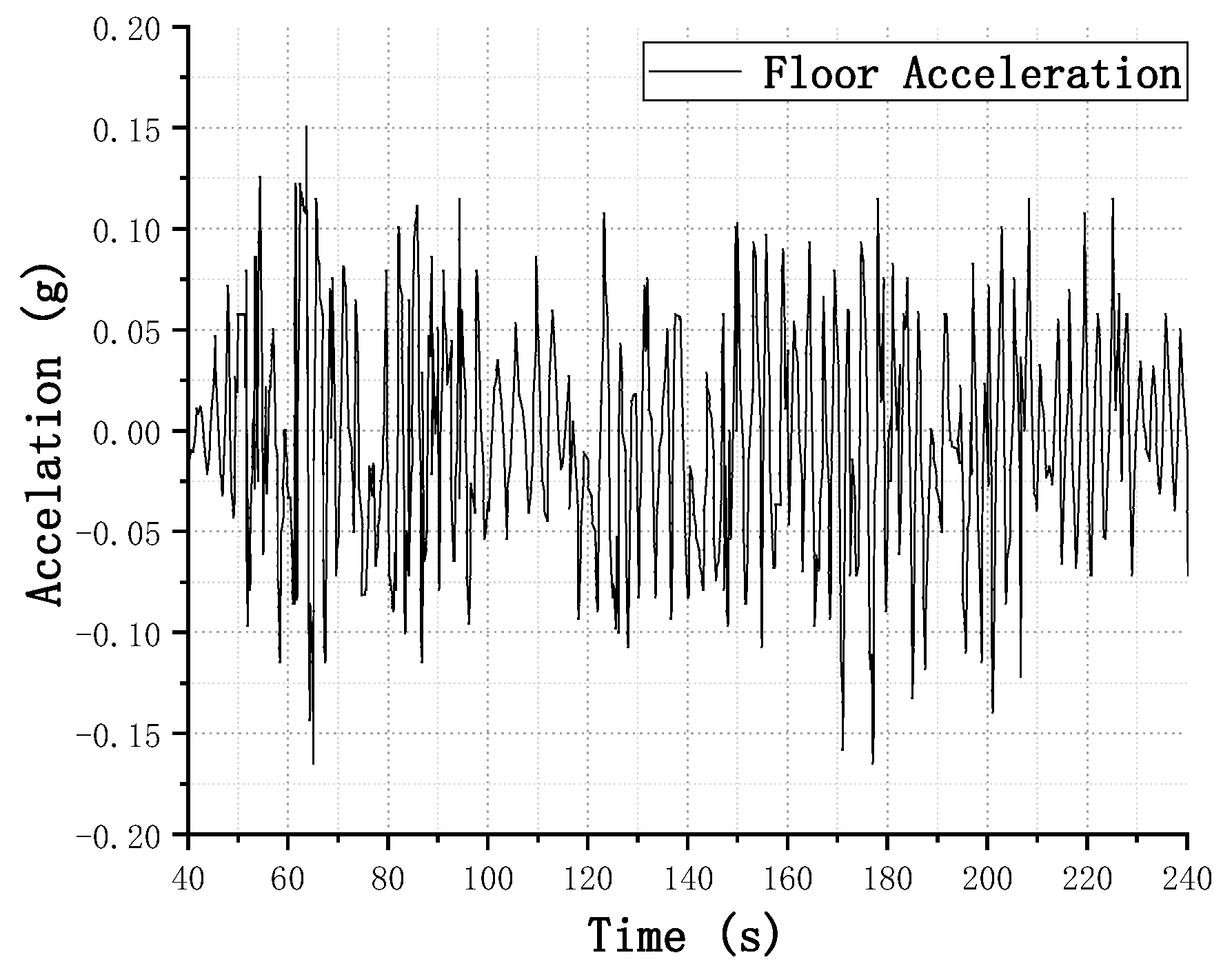
  • How will the required structural seismic dynamic responses of nonstructural components be obtained? The seismic damage to nonstructural components depends on the structural seismic dynamic responses (e.g., floor drifts and accelerations), and thus obtaining these results is essential for constructing a seismic damage scene.
  • How will the damage states (DSs) of nonstructural components be determined? A criterion is necessary to determine the DSs of nonstructural components based on specific values of the structural seismic response.
  • How will the subsequent movements of the damaged nonstructural components be simulated? After a nonstructural component is damaged, it will undergo a complex subsequent movement, e.g., a ceiling tile will fall when it breaks away from the suspended ceiling. Therefore, the subsequent movements of damaged nonstructural components need to be simulated to create a valid virtual scene of indoor seismic damage.
To resolve problem 1, a time-history analysis (THA) of the building structure can provide a detailed structural seismic response. However, the structural analysis model of the THA must be consistent with the VR model to ensure correspondence between the seismic response and the indoor scene. Consistent models for THAs and virtual scenes can be created based on building information modeling (BIM) technology [17]. A detailed three-dimensional (3D) model can be created rapidly using BIM tools—e.g., Revit [18] and Tekla [19]—and much research has been conducted on BIM-based model conversion, e.g., industry foundation classes (IFC) [20]. Therefore, a BIM-based model can be transformed to a structural analysis model and a VR model, respectively. In this way, a THA can be efficiently performed using the transformed structural analysis model, which will provide the exact corresponding seismic responses for the VR model.
For problem 2, the FEMA P-58 guidelines provide criteria for determining the DSs of nonstructural components. Establishing such criteria is challenging because numerous experiments and simulations are necessary. The Federal Emergency Management Agency (FEMA) of the United States proposed the FEMA P-58 method after a 10-year effort [21,22]. FEMA P-58 is a state-of-the-art seismic performance assessment method for structural and nonstructural components. As FEMA P-58 contains a wide range of fragility curves, it has been used extensively for predicting the seismic performance of indoor nonstructural components. Specifically, structural THAs can provide the required engineering demand parameters (EDPs) for the fragility curves, such as the inter-story drift ratio (IDR) and peak floor acceleration (PFA). Subsequently, by employing the fragility curves in FEMA P-58, the probabilities of nonstructural components experiencing different seismic DSs can be determined.
With respect to problem 3, a physics engine can provide an appropriate simulation platform. Physics engines are computer codes that specialize in calculating the complex physical behaviors (e.g., multi-body dynamics) of objects with high efficiency [23]. Currently, Havok [24], Bullet [25], and PhysX [26] are the three most popular physics engines, and these are widely used for motion simulations in the VR field [27]. For instance, Xu et al. [28] employed PhysX to simulate the movement of debris during a bridge collapse. Therefore, a physics engine can be also employed to simulate the subsequent movements of damaged nonstructural components.
In addition to simulation platforms, a physical model considering the specific seismic responses and DSs of nonstructural is also needed for the above simulations. For instance, the seismic acceleration and velocity will affect the movement of furniture, while the number of falling objects will differs depending on the DS of the ceiling. Therefore, a valid physical model on the subsequent movements of damaged nonstructural components deserves further studies.
In this study, suspended ceilings and moveable furniture are the primary focus. A virtual scene construction method for the seismic damage of suspended ceilings and moveable furniture is proposed based on FEMA P-58 and a physics engine. First, a BIM-based modeling framework is designed to create consistent structural and scene models used for the structural THA and scene construction. FEMA P-58 is then employed to determine the DSs of nonstructural components based on the results of the THA. Finally, the physical models on the movements of the damaged components are designed using a physics engine and are also validated through the experiments such as an existing shaking table test. Taking a six-story building as a case study, a virtual seismic damage scene of the indoor nonstructural components is constructed and applied in an earthquake safety drill. The outcome of this study provides well-founded scenes of the seismic damage to indoor nonstructural components for performing virtual earthquake safety drills.

2. Framework

The proposed method for construction of a virtual scene representing the seismic damage to suspended ceilings and moveable furniture includes three steps, as shown in Figure 1. Note that the full name of the abbreviations in Figure 1 can be found in Table A1 in the Appendix A.
In the first step, a structural analysis model and VR model of the building are created based on BIM, and the structural THA is performed. This step will provide important data for the damage prediction (Step 2) and movement simulation (Step 3), including EDPs, seismic responses, and VR models.
In the second step, the corresponding performance groups (PGs) in FEMA P-58 are determined for suspended ceilings and moveable furniture, and the DSs of the components are predicted to support the movement simulation in Step 3.
In the third step, the physical models of suspended ceilings and moveable furniture are created. Through a falling experiment and a shaking table test, the models are validated and some key coefficients are determined. The simulation implementation based on a physics engine is designed, and thus an integrated virtual scene of the seismic damage to indoor nonstructural components can be constructed.

3. Technical Method

3.1. BIM-Based Modeling and THA

Revit [18] is a widely used BIM program, and is adopted in this study to generate detailed 3D information models of buildings. A popular graphics engine, Unity [29], is employed for scene construction because Unity can support the VR model exported by Revit in the Filmbox (FBX) format. In addition, Unity has integrated a physics engine, PhysX [26], which can be used to simulate the movement of the damaged nonstructural components.
Converting the BIM into a structural analysis model can retain consistency with the VR model and avoid the workload of manual modeling. Several structural analysis programs can achieve this conversion, such as ETABS [30], Robot [31], and Yingjianke (YJK) [32]. In this study, YJK is used for the structural analysis because YJK has developed numerous predefined sub-models for the joints and sections in Revit [33], resulting in a highly efficient conversion. Details of the conversion process are described in the works of Xu et al. [34].
After the structural analysis model is created, THAs can be performed using YJK [34]. First, structural loads such as gravity are assigned to the model. Subsequently, the corresponding ground motion is selected for a nonlinear THA. Finally, the EDPs (e.g., IDRs and PFAs) and time-history results (e.g., velocity and acceleration) are output from the THA for the subsequent damage prediction for the components.

3.2. Damage Prediction for Suspended Ceilings and Moveable Furniture

The fragility curves in FEMA P-58 are critical for the prediction of seismic damage to nonstructural components. However, the corresponding PGs for components need to be determined before the fragility curves can be used, because these curves are classified based on the PGs in FEMA P-58.
The corresponding PG for each component can be determined according to the detailed classification criteria in FEMA P-58. These criteria involve the geometry, material, construction, and damage mechanisms of the components. The geometric and material properties can be directly obtained from the BIM, while information for the construction and damage mechanism generally need to be added manually. Therefore, a solution combining automatic and manual procedures [35] is used to determine the corresponding PGs for components.
The determination process is divided into four levels (Levels 1–4): building, story, component category, and PG. In FEMA P-58, the seismic damage is predicted story-by-story; therefore, the PG determination process is also conducted story-by-story to be consistent with FEMA P-58. A BIM (Level 1) is first split into stories (Level 2) according to the elevations of the stories. The categories of nonstructural components in each story (Level 3) are then identified in the BIM. Finally, the PGs (Level 4) are identified manually according to the attribution of component categories in the BIM and the necessary information regarding the construction and damage mechanisms. This determination process can be implemented using the application programming interface (API) of Revit [35].
Typical fragility data (e.g., identity documents (IDs) of PGs, fragility curves, required EDPs, etc.) of a suspended ceiling and movable furniture obtained using the above procedure are listed in Table 1. From Table 1, it can be observed that the seismic DSs of both suspended ceilings and movable furniture are controlled by the PFAs. Suspended ceilings have three DSs (See Figure 2), while movable furniture has only a single DS. In FEMA P-58, each DS of suspended ceilings has a clear description, e.g., the ratio of the area of falling ceiling tiles. However, the DS for movable furniture has no clear description to determine whether the furniture has been overturned or moved. Therefore, the DSs of suspended ceilings are used to determine the fallen area in the virtual scene, but the DS of the movable furniture will not be used. The movement of the furniture will be simulated directly using the data from the seismic responses and a physics engine, which is clarified in Section 3.3.
It should be noted that FEMA P-58 includes the fragility data of a wide range of nonstructural components (e.g., partitions and stairs), thus the above proposed solution can also predict seismic damage of other components and is not limited to the suspended ceilings and movable furniture mentioned in this study.

3.3. Simulation of the Movement of Damaged Nonstructural Components

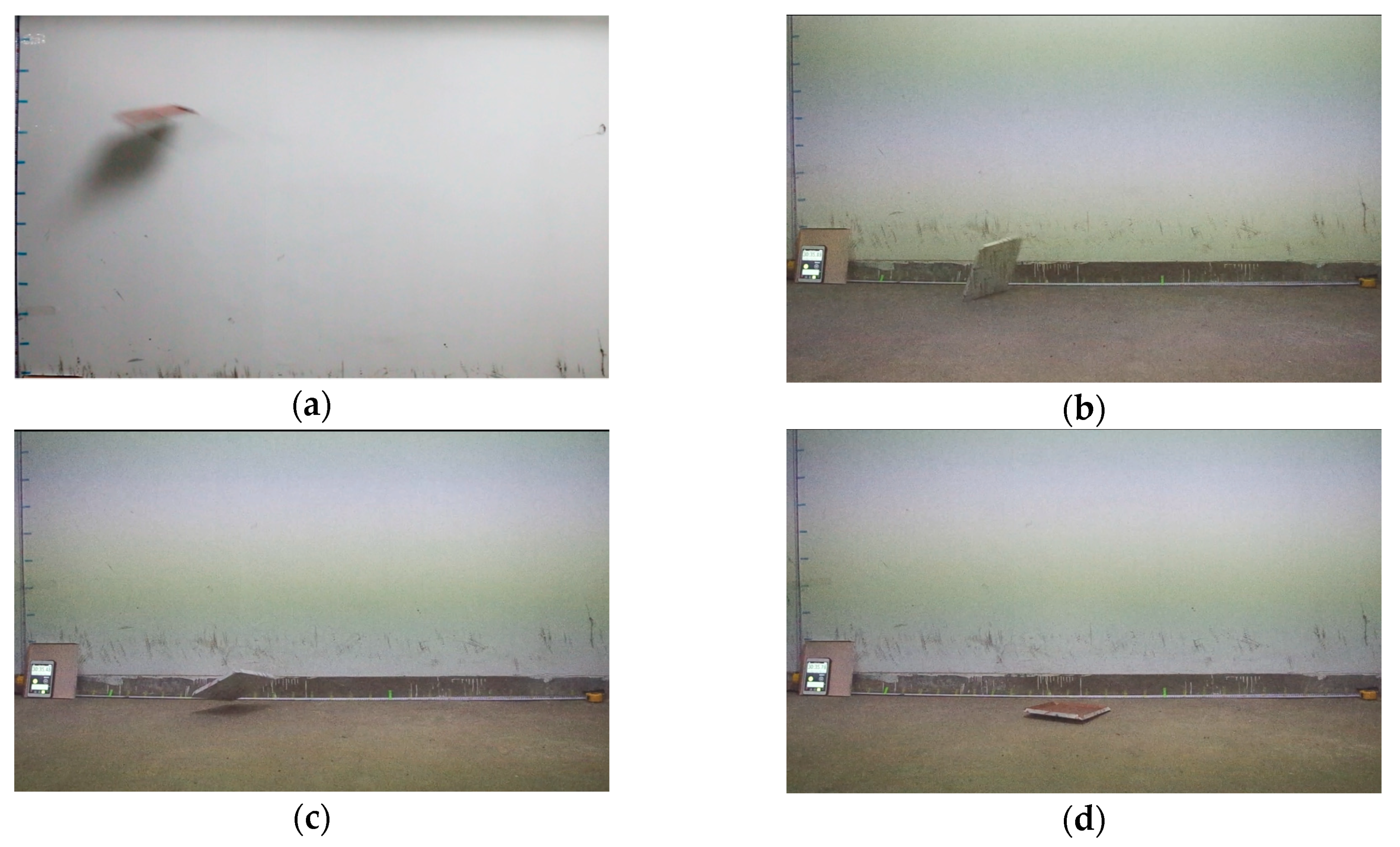
3.3.1. Suspended Ceilings

To simulate the subsequent movement of damaged ceilings, four steps need to be completed: (a) determine the simulation scenarios, including the number and positions of falling tiles; (b) create a physical model of the falling tiles for the simulations; (c) validate the physics model and determine its key coefficients; and (d) implement the simulations using a physics engine.
1. Simulation scenarios
The number and positions of falling tiles are critical for determining the simulation scenario for suspended ceilings. The area ratio of falling tiles can be determined for each DS according to FEMA P-58. Taking a typical suspended ceiling as an example (the corresponding PG ID is C3032.001a), the area ratios of falling tiles are listed for three DSs in Table 1. Owing to the complex interactions between ceiling tiles during an earthquake, the positions of falling tiles are random [36,37]. Therefore, the number of falling ceiling tiles can be determined by the corresponding ratio from the DS, while their positions can be assigned randomly in the simulation scenario.
2. Physical model of falling tiles
When a suspended ceiling suffers seismic damage, the tiles will separate from the skeleton of the ceiling and fall to the floor. As shown in Figure 3, the typical falling process for a separated tile can be divided into four stages.
In the first stage, the tile has a horizontal projectile motion with an initial velocity. The trace of the tile in the x-direction can be calculated with Equation (1)
x = v 0 t
where v0 is the initial velocity, which is equal to the floor velocity when the tile separates from the ceiling and can be obtained from the seismic response results of the THA.
Note that the air drag force (denoted as fy) in the vertical direction cannot be ignored because the area of the vertical face of a tile generally is much larger than that of the other faces, which can be calculated using Equation (2)
f y = 1 2 c ρ s v y 2
where c and ρ   are the drag coefficient and the density of the air (i.e., 1.29 kg/m3), respectively; s and vy are the vertical area and velocity of the tile, respectively.
Defining k = c ρ s/2, the movement equation for the falling tile in the y-direction can be given as
m g k ( d y d t ) 2 = m d 2 y d t 2
After solving Equation (3), the trace of the tile in the y-direction can be calculated with Equation (4)
y = m ln ( cosh ( t g k / m ) ) k
where m and g are the mass of the tile and the acceleration of gravity, respectively.
In the second stage, the tile collides with the floor. According to the rules for inelastic collisions, the vertical velocity of the tile after collision (i.e., vt2) can be calculated using Equation (5)
v t 2 = C R m f ( v f 1 v t 1 ) + m t v t 1 + m f v f 1 m t + m f
where vt1 and vt2 are the vertical velocities of the tile before and after collision, respectively; vf1 is the velocity of the floor before collision, which is equal to zero (i.e., vf1 = 0); mt and mf are the masses of the tile and floor, respectively; and CR is the coefficient of restitution.
Because mf is much larger than mt, Equation (5) can be simplified into Equation (6) as
v t 2 = C R v t 1
In the third stage, the tile will be bounced. Its path on the x- and y-direction can be calculated by Equation (1) and Equation (7), respectively.
y = v t 2 t 1 2 ( g + f y / m ) t 2
In the last stage, the tile will slide along the floor until the velocity decreases to zero. The path in the x-direction can be calculated using Equation (8)
x = v 0 t 1 2 μ g t 2
where μ is the kinetic friction coefficient between the tile and floor.
3. Validation and coefficient determination
For the above physical model of falling tiles, the four-stage movement needs to be validated and the key coefficients (i.e., c, CR, and μ ) also need to be determined. To this end, an experiment to investigate the falling process of a ceiling tile is performed.
A typical aluminum ceiling tile with a size of 300 × 300 × 0.8 mm is used as the falling tile. In this experiment, the tile is projected horizontally at three heights (i.e., 165 cm, 180 cm, and 195 cm), and then falls to a concrete floor. The entire tile falling process is recorded by video cameras, and thus the movement path of the tile can be obtained by measuring the images in the video.
In this experiment, the tile fell three times with different initial horizontal velocities for each height, and thus a total of nine movement paths of the tile were obtained. A typical movement process of the tile is shown in Figure 4, which is in agreement with the four stages in the proposed physical model, and therefore demonstrates that the proposed physical model is reasonable.
Based on the recorded movement paths and Equation (4), the drag coefficient, c, can be calculated; it is in the range of 0.92–1.05. In this study, the mean value of c (i.e., 0.97) is used. Through measuring the images in the video of the experiment, the velocities before and after collision are obtained, which allows the coefficient of restitution, CR, to be calculated. The range and mean value of CR are 0.23–0.37 and 0.30, respectively. The kinetic friction coefficient, μ , between the tile and concrete floor is also measured, and the value is 0.37 ± 0.01. These key coefficients will be used to simulate a falling tile in the physics engine.
4. Implementation using a physics engine
Although the proposed physical model can describe the dynamic nature of the movements of the damaged ceiling tiles, an implementation approach based on the physical model is still needful for simulating such movements. As mentioned previously, PhysX is employed as the default physical engine in Unity. Furthermore, the proposed four-stage physical model has been embedded in PhysX. Hence, PhysX is a good simulation platform for the damaged ceiling tiles.
Four steps need to be done for implementing the movement simulations of the damaged ceiling tiles, as follows:
(1) Create rigid-body models
Using PhysX, each ceiling tile is defined as a rigid body. In this step, the geometrical information of ceiling tiles in Unity is imported to PhysX to create the corresponding rigid bodies.
(2) Determine key coefficients
The key coefficients of rigid-body models have significant influences on the accuracy of the movement simulation of ceiling tiles. The key coefficients (e.g., c, CR, and μ ) determined from the experiment can be defined in the attribute tables of rigid bodies in PhysX.
(3) Define initial physical status
Except for gravity, the initial physical status of a tile only includes a velocity, which can be defined using the function “setLinearVelocity()” in PhysX. The initial velocity is equal to the floor velocity when the tile separates from the ceiling and can be obtained from the seismic response results of the THA.
(4) Add the forces
To create a corresponding scenario for different DSs, a solution of random gravity activation is designed using PhysX. According to the DS of the ceiling, the class of “Random.Range” in Unity is used to randomly select tiles to satisfy the corresponding scenario, e.g., 5% of the tiles are selected at DS1. Subsequently, the gravities of selected tiles will be activated in the following simulation using the command “useGravity = true” in PhysX.
Through the above steps, the entire falling process of a tile can be simulated using PhysX.

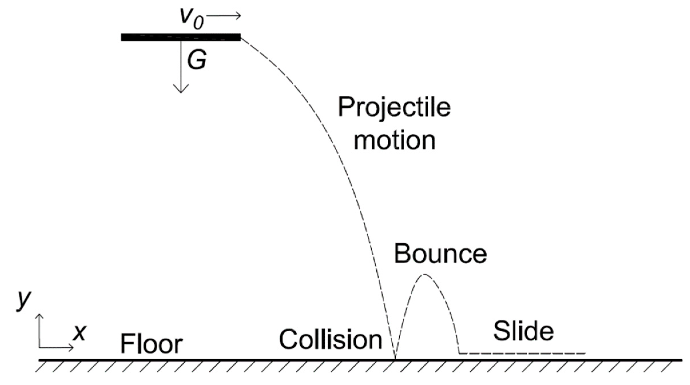
3.3.2. Movable furniture

Movable furniture will move or overturn during an earthquake. To simulate such movements, three steps need to be performed: (a) create a physical model of the movable furniture; (b) implement the simulation in PhysX; and (c) validate the simulation results.
1. Physical model
The physical model of the movable furniture is shown in Figure 5. A furniture object on the floor will be subjected to an inertial force (denoted as F) caused by the floor acceleration (denoted as afloor) of the structural seismic response. In addition, the object will also be subjected to gravity (i.e., G), a friction force (i.e., Ff), and a normal force (denoted as N).
In the y-direction, gravity is equal to the normal force to maintain balance, i.e., G = N, while in the x-direction, the inertial force, F, and friction force, Ff, will cause the object to move. The moment caused by the inertial force, F, and gravity, G, determines whether the object will overturn. Therefore, these forces will fully determine the movement status of the object, which can be calculated using the equations
F f = N μ = G μ = m g μ
F = m a f l o o r
where m and μ are the mass of the object and the friction coefficient between the object and the floor, respectively.
2. Simulation implementation
The Equation (9) has been embedded in PhysX, which is similar with the aforementioned simulation implementation of ceiling tiles, therefore the same implementation steps are performed for movable furniture, as follows:
(1) Create rigid-body models
In this study, all of the movable furniture is modeled as rigid bodies.
(2) Determine key coefficients
The masses and friction coefficients of movable furniture are key coefficients of the physical models. The masses can be calculated by using the component data in BIM, while friction coefficients can be determined according to the empirical values for common materials [38].
(3) Define initial physical status
With regard to movable furniture, the initial physical status is static, thus no additional work is needed.
(4) Add the forces
Using the function “AddForce()” in PhysX, an inertial force can be applied at the centroid of a rigid body. The inertial force can be calculated with Equation (10) using the floor accelerations obtained from the results of the seismic THA. By activating the gravity, the friction force and normal force will be calculated automatically by PhysX according to Equation (9). Based on these forces, the movements of these objects will be also automatically simulated by PhysX.
3. Validation with a shaking table test
To validate the proposed physical model for movable furniture, an existing shaking table test is employed for comparing with the simulation result. Specifically, this is a full-scale shaking table test of a five-story steel frame structure (see Figure 6a), which was performed by the National Research Institute for Earth Science and Disaster Resilience (NIED) of Japan using the E-Defense shaking table [39]. Some movable furniture (e.g., a wardrobe and lamp) are placed in the third story of the structure, and the entire shaking process of the indoor furniture was recorded, as shown in Figure 6b.
For comparison, the above experimental scene was first replicated with the proposed BIM-based modeling framework and imported to Unity. Subsequently, the physical models of the indoor furniture were created in PhysX. The masses and friction coefficients of the indoor furniture in Figure 6b are listed in Table 2. The masses of the pieces of furniture are calculated based on their densities and volumes, which can be obtained from the component attributes in the BIM, while the friction coefficients are empirical values for common materials [38]. In addition, the recorded time-history data [39] is used directly for the floor acceleration, as shown in Figure 7.
Through the proposed physical model, the movement of the furniture is simulated in PhysX. The comparison between the simulation and the shaking table test is shown in Figure 8, and the results indicate that the simulation results agree with the actual process in the shaking table test. Therefore, the proposed physical model can produce a valid virtual earthquake scene for the indoor movable furniture.

4. Case Study

4.1. Overview

A six-story office building with a reinforced-concrete frame structure in Beijing, China is selected as the case study. The information model for this building is created in Revit, as shown in Figure 9a. A meeting room on the fifth floor is used to construct the virtual indoor earthquake scene, and the suspended ceiling and movable furniture including a desk, several chairs, a television, and a bookcase are placed in the room, as shown in Figure 9b.

4.2. Model Conversion and Structural THA

The 3D model of the meeting room in this case study is exported in the FBX format to construct the earthquake scene in Unity, while the structure of the entire building is converted to YJK to perform the THAs, which saves manual modeling workloads for the scene constructions and THAs.
According to the seismic design code of China [40], the peak ground acceleration (PGA) for the maximum considered earthquake is 0.4 g in Beijing. Note that different earthquake records with the same PGA may cause different structural responses. Accordingly, the damage states (e.g., the fallen area of the suspended ceilings) and physical parameters (e.g., the initial velocities of the separated tiles) of nonstructural components are also different, leading to various indoor earthquake scenes. In this study, the widely used El Centro ground motion with a PGA of 0.4 g is selected to only demonstrate the proposed scene construction method. Using a nonlinear THA in YJK, the EDPs required for the subsequent predictions are calculated (see Table 3), and detailed structural time-history responses are also obtained for the simulations of the movement of nonstructural components.

4.3. Damage Prediction

The corresponding PG in FEMA P-58 needs to be determined for the suspended ceiling in this meeting room. According to the proposed solution, the PG ID of the suspended ceiling is C3032.001a, and the corresponding fragility curve is shown in Figure 2. According to the PFA on the fifth story in Table 3, the fragility curve shows that the probabilities corresponding to DS1, DS2, and DS3 for the suspended ceiling are 15%, 0.9%, and 0.1%, respectively. Therefore, the most likely damage state is DS1, which determines the ratios (i.e., 5%, see Table 1) of the fallen area of the suspended ceiling in the subsequent simulation. Consequently, the number of the separated tiles can be determined. Note that the DSs of the movable furniture are unnecessary because their movement during an earthquake will be simulated directly.

4.4. Movement Simulation

4.4.1. Suspended Ceilings

The physical model of the ceiling tiles are created in PhysX using the parameters obtained from the falling experiment in this study. Through the proposed simulation method, the separated tiles comprise 5% of the total ceiling area (i.e., the ratio corresponding to DS1, see Table 1). These tiles are randomly selected, and their gravities are activated (see Figure 10a). The floor velocity when the acceleration reaches the maximum value is used as the original velocity of the selected tiles. The falling process of these tiles is simulated, as shown in Figure 10b.

4.4.2. Movable Furniture

Using the BIM-based modeling solution, 3D models of some movable furniture objects are created and imported into the virtual scene in Unity, as shown in Figure 11a. The corresponding physical models for these pieces of furniture are created through the proposed method, and their inertial forces are calculated based on the time-history data for the floor acceleration from the THA. The movement process for the furniture is simulated, and their final statuses are presented in Figure 11b.

4.4.3. Integrated Indoor Earthquake Scene

The simulations of the suspended ceiling and movable furniture are integrated to create a dynamic virtual indoor earthquake scene, as shown in Figure 12. These simulations are based on the structural THA and the seismic damage prediction using FEMA P-58, thus the integrated virtual earthquake scene is well-founded.

4.5. Technical Evaluation

To evaluate the reasonableness of the proposed method, three earthquake scenes are constructed and compared as demonstrated as Figure 13. According to the seismic design code of China [40], earthquakes can be classified into three levels (i.e., minor, moderate, and severe), and the constructed three scenes correspond to such three levels. For the THA of the building of case study in Beijing, the El Centro ground motion is adopted and the PGAs of the minor, moderate and severe earthquake are 0.07 g, 0.2 g, and 0.4 g, respectively [40]. Through the proposed method, the original scene and three indoor earthquake scenes are shown in Figure 13. In the minor earthquake scene, only the bookcase overturns, whereas both bookcase and television overturn in the moderate and severe earthquake scenes. Furthermore, ceiling tiles also fall in the severe earthquake scene. Therefore, the constructed indoor earthquake scenes exhibit more severe damage with the development of earthquake levels, which indicates the reasonableness of the proposed method.

4.6. Parametric Study

As an only parameter for a given ground motion, PGA has significant influence on the earthquake indoor scene. To analyze such influence, the horizontal displacements of a ceiling tile and a chair in the constructed scene with different PGAs are studied, respectively. As aforementioned, PGA for the maximum considered earthquake is 0.4 g for the building in case study [40], hence the range of PGA is from 0 to 0.4 g. The THAs of the building are performed using the El Centro ground motion within the PGA of 0–0.4 g, and thus the movements of a ceiling tile and a chair are simulated based on the results of the THAs and the proposed physical models, respectively. Consequently, the curves between the simulated horizontal displacements and PGAs are illustrated in Figure 14.
It can be observed that the relationship between the horizontal displacements of a ceiling tile and PGAs exists two stages. In the first stage, the ceiling tile does not separate from the entire ceiling according to the corresponding fragility curve in FEMA P-58, thus the horizontal displacement is zero. The threshold of PGA when the ceiling tile starts to fall is 0.3 g, as shown in Figure 14. In the second stage, the horizontal displacements have a linear relationship with PGAs. Because the building is strictly designed following the seismic design code of China [40], its structure almost keeps elastic within the PGA of 0–0.4 g, leading to the linear seismic response (e.g., floor velocities and accelerations) with PGAs. In addition, the horizontal displacements of a falling tile also have a linear relationship with the velocities according to Equation (1). Consequently, the relationship between the horizontal displacements of the tile and PGAs is linear. Contrastingly, the horizontal displacements of the chair has a square relationship with the floor accelerations according to Equation (10) and the rigid body dynamics [26]. Therefore, as shown in Figure 14, the horizontal displacements of the chair have a nonlinear relationship with PGAs.

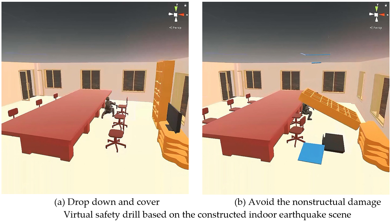
4.7. Virtual Earthquake Safety Drill

To help occupants avoid physical injuries induced by nonstructural components, a virtual earthquake safety drill based on the above constructed earthquake scene (see Figure 12) is performed. In this drill, HTC Vive [41] is employed to enable the trainee experiences such scene, because it can use a widely used API, OpenVR [42], to easily connect to Unity. By using HTC Vive, the framework of the virtual drill is implemented, as shown in Figure 15. In this framework, the trainee can experience the 3D indoor earthquake scene in first-person view through the HTC Vive headset and his survival responses are captured in real time through the hand motion controllers and other trackers. In addition, the drill process can be also shown in third-person view to observe the survival responses of the trainee.
Two virtual drills with the same earthquake scene (see Figure 12) and the same trainee are performed in succession, and their drill processes are presented in Figure 16 and Figure 17. In the first drill, the trainee is not fully aware of the potential hazard caused by nonstructural components. Consequently, he does not avoid the overturned bookcase in time and is hit by the bookcase, as shown in Figure 16b. In the second drill, the trainee has been aware of the nonstructural hazards. In this way, he drops down and covers his body with the desk to avoid the possible hazards, as presented in Figure 17a. By doing this, he is not hit by the overturned bookcase (see Figure 17b) and succeeds in protecting himself in the virtual earthquake. Such different consequences indicate that the constructed earthquake scene can improve the awareness to the hazards of nonstructural components for the trainees and thus help them respond to earthquake safely. Note that the videos of the above two drills are available in Supplementary Materials.

5. Conclusions

A method for the construction of a virtual scene representing the seismic damage to suspended ceilings and moveable furniture is proposed and validated by the experiments. Using the proposed method, an integrated indoor virtual earthquake scene of a six-story building is constructed and applied in an earthquake safety drill. Some conclusions are made as follows:
  • The designed BIM-based modeling solution can efficiently create the consistent structural analysis and VR models of a building.
  • The solution based on structural seismic THA and FEMA P-58 can provide detailed seismic damage results required to construct the earthquake scene for nonstructural components.
  • Physical models and corresponding physics-engine-based implementation of suspended ceilings and moveable furniture are created, allowing the movement of these components to be simulated reasonably.
  • The proposed method constructs a well-founded scene representing the seismic damage to indoor nonstructural components, which can be used to perform virtual indoor earthquake safety drills and thus improve the earthquake survival ability of occupants.
Note that FEMA P-58 includes the fragility data of various nonstructural components. Therefore, the proposed virtual scene construction method based on FEMA P-58 and a physics engine can be used for other nonstructural components if the corresponding physical models are established. In addition, the propose method is not limited to the office building in Case study and can be used in other buildings, such as hospital buildings. It is also noted that the fragility curve of movable furniture in FEMA P-58 is not adopted, thus the uncertainty of the damage of movable furniture is not fully considered. It is recommended to use a Monte Carlo approach together with the proposed physical model to be able to consider such uncertainty.
The proposed method in this study can produce numerous indoor earthquake scenes induced by nonstructural components, which provides sufficient training data (e.g., images and videos) for the identification of the potential nonstructural seismic damage based on artificial intelligence (AI). Such AI-based identification can be implemented on smartphones as an application. This application will identify structural and nonstructural components in real-time through object detection and predict the possible seismic motion of nonstructural components based on a predefined intensity. Such applications would be used by the public and based on their own home furniture. The above research based on AI will be deeply investigated in the future.

Supplementary Materials

The following are available online at https://www.mdpi.com/2076-3417/9/17/3465/s1.

Author Contributions

Conceptualization, Z.X.; Methodology, H.Z.; Validation, W.W.; Writing—original draft, Z.X.; Writing—review & editing, Z.Y.

Funding

The authors are grateful for the financial support received from the National Key R&D Program of China (no. 2018YFC0809900), the National Natural Science Foundation of China (no. 51978049) and the Fundamental Research Funds for the Central Universities (no. FRF-BD-18-007A).

Conflicts of Interest

The authors declare no conflict of interest.

Appendix A

Table A1. Nomenclature and abbreviations
Application Programming InterfaceAPIInter-Story Drift RatioIDR
Artificial intelligenceAINational Research Institute for Earth Science and Disaster ResilienceNIED
Building information modelingBIMPeak floor accelerationPFA
Damage stateDSPerformance groupPG
Federal Emergency Management AgencyFEMAPeak ground accelerationPGA
FilmboxFBXThree-dimensional3D
Engineering demand parameter EDPTime-history analysisTHA
Identity documentIDVirtual realityVR
Industry foundation classesIFCYingjiankeYJK

References

  1. Lu, X.; Lu, X.; Guan, H.; Ye, L. Collapse simulation of reinforced concrete high-rise building induced by extreme earthquakes. Earthq. Eng. Struct. Dyn. 2013, 42, 705–723. [Google Scholar] [CrossRef]
  2. Li, Y.; Lu, X.; Guan, H.; Ye, L. An energy-based assessment on dynamic amplification factor for linear static analysis in progressive collapse design of ductile RC frame structures. Adv. Struct. Eng. 2014, 17, 1217–1225. [Google Scholar] [CrossRef]
  3. Li, Y.; Lu, X.; Guan, H.; Ye, L. Progressive collapse resistance demand of RC frames under catenary mechanism. ACI Struct. J. 2014, 111, 1225–1234. [Google Scholar] [CrossRef]
  4. Xu, Z.; Lu, X.; Guan, H.; Tian, Y.; Ren, A. Simulation of earthquake-induced hazards of falling exterior non-structural components and its application to emergency shelter design. Nat. Hazards 2016, 80, 935–950. [Google Scholar]
  5. Xu, Z.; Lu, X.; Guan, H.; Lu, X.; Ren, A. Progressive-collapse simulation and critical region identification of a stone arch bridge. J. Perform. Constr. Facil. 2013, 27, 43–52. [Google Scholar] [CrossRef]
  6. Xu, Z.; Lu, X.; Guan, H.; Han, B.; Ren, A. Seismic damage simulation in urban areas based on a high-fidelity structural model and a physics engine. Nat. Hazards 2014, 71, 1679–1693. [Google Scholar] [CrossRef]
  7. Han, L.; Cheng, J.; An, Y.; Fang, L.; Jiang, C.; Chen, B.; Wu, Z.; Liu, J.; Xu, X.; Liu, R.; et al. Preliminary report on the 8 August 2017 Ms 7.0 Jiuzhaigou, Sichuan, China, Earthquake. Seismol. Res. Lett. 2018, 89, 557–569. [Google Scholar] [CrossRef]
  8. Shi, B.; Liu, G.; Li, L.; Tang, S.; Wang, J.; Xie, M.; Dai, X.; He, J.; Zhang, Y.; Tang, Y.; et al. Injury characteristics and therapeutic strategy of patients injured in “8.8” Jiuzhaigou earthquake. Chin. J. Repar. Reconstr. Surg. 2018, 32, 358–362. [Google Scholar]
  9. Solinska-Nowak, A.; Magnuszewski, P.; Curl, M.; French, A.; Keating, A.; Mochizuki, J.; Liu, W.; Mechler, R.; Kulakowska, M.; Jarzabek, L. An overview of serious games for disaster risk management–Prospects and limitations for informing actions to arrest increasing risk. Int. J. Disaster Risk Reduct. 2018, 31, 1013–1029. [Google Scholar] [CrossRef]
  10. Tarnanas, I.; Manos, G.C. Using virtual reality to teach special populations how to cope in crisis: The case of a virtual earthquake. Stud. Health Technol. Inform. 2001, 81, 495–501. [Google Scholar]
  11. Lovreglio, R.; Gonzalez, V.; Feng, Z.; Amor, R.; Spearpoint, M.; Thomas, J.; Trotter, M.; Sacks, R. Prototyping virtual reality serious games for building earthquake preparedness: The Auckland City Hospital case study. Adv. Eng. Inform. 2018, 38, 670–682. [Google Scholar] [CrossRef] [Green Version]
  12. Lovreglio, R.; Gonzalez, V.; Amor, R.; Spearpoint, M.; Thomas, J.; Trotter, M.; Sacks, R. The need for enhancing earthquake evacuee safety by using virtual reality serious games. In Proceedings of the Joint Conference on Computing in Construction, Proceedings of the Lean and Computing in Construction Congress: Vol. 1, Heraklion, Greece, 16–21 Jul 2017; Heriot-Watt University: Edinburgh, UK, 2017; pp. 381–389. [Google Scholar]
  13. Kuester, F.; Hutchinson, T.C. A virtualized laboratory for earthquake engineering education. Comput. Appl. Eng. Educ. 2007, 15, 15–29. [Google Scholar] [CrossRef]
  14. Shin, Y.S. Virtual reality simulations in Web-based science education. Comput. Appl. Eng. Educ. 2002, 10, 18–25. [Google Scholar] [CrossRef]
  15. Xu, F.; Chen, X.; Ren, A.; Lu, X. Earthquake disaster simulation for an urban area, with GIS, CAD, FEA, and VR integration. Tsinghua Sci. Technol. 2008, 13, 311–316. [Google Scholar] [CrossRef]
  16. Li, C.; Liang, W.; Quigley, C.; Zhao, Y.; Yu, L.-F. Earthquake safety training through virtual drills. IEEE Trans. Vis. Comput. Graph. 2017, 23, 1275–1284. [Google Scholar] [CrossRef] [PubMed]
  17. Volk, R.; Stengel, J.; Schultmann, F. Building Information Modeling (BIM) for existing buildings—Literature review and future needs. Autom. Constr. 2014, 38, 109–127. [Google Scholar] [CrossRef]
  18. Autodesk. Revit: Multidisciplinary Bim Software for Higher Quality, Coordinated Designs. Available online: https://www.autodesk.com/products/revit/overview (accessed on 5 January 2019).
  19. Trimble. Tekla: The Most Advanced Bim Software for Structural Workflow. Available online: https://www.tekla.com/products/tekla-structures (accessed on 7 January 2019).
  20. Eastman, C.M. Industry Foundation Classes. In Building Product Models; CRC Press: Boca Raton, FL, USA, 2018; pp. 279–318. [Google Scholar] [CrossRef]
  21. Federal Emergency Management Agency (FEMA). Seismic Performance Assessment of Buildings: Volume 1—Methodology; FEMA: Washington, DC, USA, 2012.
  22. Federal Emergency Management Agency (FEMA). Seismic Performance Assessment of Buildings: Volume 2—Implementation; FEMA: Washington, DC, USA, 2012.
  23. Millington, I. Game Physics Engine Development: How to Build a Robust Commercial-Grade Physics Engine for your Game; CRC Press: Boca Raton, FL, USA, 2007. [Google Scholar]
  24. Havok. Technology for Games. Available online: https://www.havok.com/ (accessed on 11 January 2019).
  25. Bullet. Real-Time Physics Simulation. Available online: https://pybullet.org/wordpress/ (accessed on 7 January 2019).
  26. Nvidia. A Multi-Platform Physics Solution. Available online: https://developer.nvidia.com/physx-sdk (accessed on 6 January 2019).
  27. Erez, T.; Tassa, Y.; Todorov, E. Simulation tools for model-based robotics: Comparison of Bullet, Havok, MuJoCo, ODE and PhysX. In Proceedings of the 2015 IEEE International Conference on Robotics and Automation (ICRA), Seattle, WA, USA, 25–30 May 2015; pp. 4397–4404. [Google Scholar]
  28. Xu, Z.; Lu, X.; Guan, H.; Ren, A. Physics engine-driven visualization of deactivated elements and its application in bridge collapse simulation. Autom. Constr. 2013, 35, 471–481. [Google Scholar] [CrossRef] [Green Version]
  29. Unity. The World’s Leading Real-Time Creation Platform. Available online: https://unity.com/ (accessed on 5 January 2019).
  30. Tsay, R.J. A study of BIM combined with ETABS in reinforced concrete structure analysis. IOP Conf. Ser. Earth Environ. Sci. 2019, 233, 022024. [Google Scholar] [CrossRef]
  31. Autodesk. Robot Structural Analysis Professional. Available online: https://www.autodesk.com/products/robot-structural-analysis/overview (accessed on 2 February 2019).
  32. YJK. Interface between YJK and Revit. Available online: http://www.yjk.cn/cms/item/view?table=prolist&id=16 (accessed on 8 January 2019).
  33. Liu, Z.-Q.; Zhang, F.; Zhang, J. The building information modeling and its use for data transformation in the structural design stage. J. Appl. Sci. Eng. 2016, 19, 273–284. [Google Scholar]
  34. Xu, Z.; Zhang, Z.; Lu, X.; Zeng, X.; Guan, H. Post-earthquake fire simulation considering overall seismic damage of sprinkler systems based on BIM and FEMA P-58. Autom. Constr. 2018, 90, 9–22. [Google Scholar] [CrossRef]
  35. Xu, Z.; Zhang, H.; Lu, X.; Xu, Y.; Zhang, Z.; Li, Y. A prediction method of building seismic loss based on BIM and FEMA P-58. Autom. Constr. 2019, 102, 245–257. [Google Scholar] [CrossRef]
  36. Motosaka, M.; Mitsuji, K. Building damage during the 2011 off the Pacific coast of Tohoku Earthquake. Soils Found. 2012, 52, 929–944. [Google Scholar] [CrossRef] [Green Version]
  37. Badillo-Almaraz, H.; Whittaker, A.S.; Reinhorn, A.M. Seismic fragility of suspended ceiling systems. Earthq. Spectra 2007, 23, 21–40. [Google Scholar] [CrossRef]
  38. ToolBox Engineering. Friction and Friction Coefficients. Available online: https://www.engineeringtoolbox.com/friction-coefficients-d_778.html (accessed on 6 January 2019).
  39. Takuya, N. Seismic damage reconstruction of non-structural components in high building: Full-scale experiment in E-Defense shaking table (rewarded by Architectural Institute of Japan). J. Archit. Build. Sci. 2010, 83, 1607. (In Japanese) [Google Scholar]
  40. Ministry of Housing and Urban-Rural Development. Code for Seismic Design of Building (GB 50011-2010); China Architecture Industry Press: Beijing, China, 2016. (In Chinese) [Google Scholar]
  41. Kelly, J.W.; Klesel, B.C.; Cherep, L.A. Visual stabilization of balance in virtual reality using the HTC Vive. ACM Trans. Appl. Percept. 2019, 16, 8. [Google Scholar] [CrossRef]
  42. Egger, J.; Gall, M.; Wallner, J.; Boechat, P.; Hann, A.; Li, X.; Chen, X.; Schmalstieg, D. HTC Vive MeVisLab integration via OpenVR for medical applications. PLoS ONE 2017, 12, e0173972. [Google Scholar] [CrossRef] [PubMed]
Figure 1. Framework of this study.
Applsci 09 03465 g001
Figure 2. Fragility curve for the suspended ceiling.
Applsci 09 03465 g002
Figure 3. Falling process for a ceiling tile in the physical model.
Applsci 09 03465 g003
Figure 4. Falling process of a ceiling tile in the experiments, (a) projectile motion; (b) collision; (c) bounce; (d) slide.
Applsci 09 03465 g004
Figure 5. Physical model of movable furniture.
Applsci 09 03465 g005
Figure 6. Shaking table test of indoor movable furniture, (a) full-scale 5-story shaking table test; (b) indoor scene on the third story.
Applsci 09 03465 g006
Figure 7. Recorded time-history data for the floor acceleration of the third story.
Applsci 09 03465 g007
Figure 8. Comparison between the simulation and shaking table test results (Left: results from the video of the shaking table test; Right: simulation results using the proposed physical model), (a) original scene; (b) the lamp starts to fall; (c) the lamp falls down to the floor; (d) the wardrobe overturns.
Applsci 09 03465 g008aApplsci 09 03465 g008b
Figure 9. The selected building in case study, (a) information model; (b) indoor scene.
Applsci 09 03465 g009
Figure 10. Simulation of falling ceiling tiles, (a) the separated tiles at DS1; (b) final status of falling tiles.
Applsci 09 03465 g010
Figure 11. Movement simulation of the movable furniture, (a) original status; (b) final status
Applsci 09 03465 g011
Figure 12. Integrated indoor earthquake scene, (a) original scene; (b) furniture overturns; (c) ceiling titles fall; (d) ceiling titles fall to the floor.
Applsci 09 03465 g012
Figure 13. Constructed indoor scenes for different earthquake levels, (a) original scene; (b) minor earthquake; (c) moderate earthquake; (d) severe earthquake.
Applsci 09 03465 g013
Figure 14. Horizontal displacements of a ceiling tile and a chair with different PGAs.
Applsci 09 03465 g014
Figure 15. Framework of the virtual drill, (a) first-person view; (b) third-person view; (c) real drill view.
Applsci 09 03465 g015
Figure 16. The first drill without the awareness of nonstructural damage, (a) response; (b) consequence.
Applsci 09 03465 g016
Figure 17. The second drill with the awareness of nonstructural damage, (a) response; (b) consequence.
Applsci 09 03465 g017
Table 1. Typical fragility data for suspended ceilings and movable furniture
ComponentTypical PG ID The Required EDPDSFragility Curves
Suspended ceilingC3032.001aPFADS1: 5% of ceiling grid and tile damage
DS2: 30% of ceiling grid and tile damage
DS3: 50% of ceiling grid and tile damage
Figure 2
Movable furnitureE2022.001PFADS1: Wall units need to be adjusted and straightened. Some elements are bent/damaged and need to be replaced.Reference [22]
Table 2. Masses and friction coefficients of indoor furniture
FurnitureMass (kg)Friction Coefficients
The lower cabinet (Left)109.820.62
The lower cabinet (Right)159.190.62
The taller wardrobe135.960.62
Lamp2.700.50
Table 3. EDPs required for the prediction of seismic damage
StoryPeak Floor Velocity (mm/s)PFA (g)
1127.7490.232
2350.0150.541
3542.8160.714
4688.4880.829
5862.1500.873
6997.7421.191

