1. Introduction
Digital displays are an integral part of our everyday life, and they are still evolving in multiple directions. The most obvious branch is evolution towards larger screen size, higher resolution and improved efficiency. Nevertheless, the new revolution in display technologies is brewing within the segment of personalized wearable displays. Currently this niche is dominated by virtual reality (VR) head-mounted displays mainly for gaming and entertainment purposes. Nevertheless, it is expected that in the next few following years augmented reality (AR) displays will rapidly catch up and overtake the dominant position in the wearable head-mounted display segment [
1].
Augmentation of reality has been known since the late 16th century, when the principles of what is known today as the Pepper’s ghost illusion were first described by Giambattista della Porta. With the help of an angled large glass pane and a hidden projection system, an observer can be made to perceive the presence of objects which are not actually there. In essence, the very same principle is still used nowadays in all kinds of AR displays, where also an optical image combiner is used to fuse the light from the ambient surrounding with digital projected information. Until recently AR head-up display systems mainly could be found in military aircraft; nevertheless, as there is a virtually limitless potential for augmenting reality, head-up systems have creeped also into the consumer automotive segment but it does not stop there. With miniaturization, growth of computational power, and perfection of other key components essential to true AR (mainly positional tracking and spatial awareness), individual head-mounted AR displays are also starting to slowly appear on the market. The vision for AR applications is huge—it is foreseen as a personal assistant and guide in various workflows—starting from image-guided surgery, to manufacturing and maintenance, among many other things. Nonetheless, existing display technologies have been initially designed to show relatively rudimentary information—such as pictograms, limited text, geometric shapes, etc., which is not up to the envisioned task. In this work we review the approach that has been taken until now in development of near-to-eye AR displays, what are the challenges, and how manufacturers and scientists attempt to overcome them. We briefly analyze the future prospects in the development of AR display technologies and examine our own solution to yield a practical AR near-to-eye display hardware oriented towards professional work.
2. General Concept of Wearable AR Display
One of the key application areas of AR displays is in professional high-complexity work—especially where errors can cause devastating consequences. These are mainly high-complexity or critical tasks, which would greatly benefit from additional helpful information in the field-of-view of the operator. For example, when dealing with the assembly of complex mechanisms with a very high number of parts, it is tedious to consult a separate (written) manual—this can cause errors and greatly slows down the process. By implementing the manual in an easily comprehendible digital-assembly assistant, which is viewed in real-time through means of AR display, the pace of process would increase, the number of errors would decrease, and the overall productivity would be much improved. Similar gains are also expected in medical disciplines, military and tactical tasks, engineering and construction, etc. Moreover, augmented reality displays would open up new possibilities also for creative professions—providing means to view and communicate interior designs, architectural solutions, etc., to other people through augmentation of the actual environment.
From these examples, it is obvious that many tasks are performed by looking at a close distance—up to an arm’s reach. Thus, one of the most important prerequisites of modern AR display systems is capability of displaying a natural-looking 3D image at these short distances. Other things include sufficient field-of-view (FOV), both horizontally and vertically, with high angular resolution. Furthermore, as the display devices could be used indoors as well as outdoors, the ambient light levels would vary greatly. The challenge is to match the brightness of the virtual image to the ambient levels in case of brightly-lit outdoor environments and providing versatility to adopt to low lighting levels without sacrificing light throughput from the real world. The dependent challenges include fitting all the optical and electronics components into a lightweight and compact footprint, optimizing energy consumption and ensuring superb positional tracking/spatial awareness capability, among other more minor issues. Nevertheless, on the background of all things needed, development of optical solutions is still the most challenging and hardest issue.
In light of this, the approach of wearable AR displays has split into two—smart glasses and more professional work-inclined AR wearable displays or headsets. Nevertheless, it must be noted that this division is rather loose. Typically, what is meant by smart glasses is a small display built into normal-appearance glasses, thus providing a user with a discrete display. Currently these displays are rather rudimentary and intended for depiction of very limited graphical information—mostly pictograms and basic text. Moreover, often these are monocular systems with no means of representing 3D content. The other branch, on the other hand, is true stereoscopic display systems capable of 3D image representation and ensuring spatial tracking, which consequently makes them considerably bulkier. Though not currently, but rather in the distant future, it is envisioned that both of these branches will converge towards a sleek glasses design with full functionality of stereoscopic systems.
Further we focus only on stereoscopic head-mounted AR displays and ways of improving their image performance.
3. Stereoscopic Head-Mounted AR Displays
For professional tasks, a key component is true 3D spatial awareness, thus the augmenting digital content has to be aligned to the real 3D world precisely. Consequently, for this, both eyes of the observer have to be presented with an image. The most pressing issue with current AR displays is that utilization of basic stereoscopy has severe limitations. In this case, the sensation of 3D depth relies on binocular disparities as the strongest source of 3D depth [
2]. Nevertheless, the image is at a fixed focal distance which requires fixed accommodation on the given focal plane, while the vergence of human visual system has a freedom for variation. As a consequence, naturally coupled accommodation and vergence of eyes becomes forcefully decoupled causing the vergence–accommodation conflict (VAC), possible effects of which are well known from VR headset experiences and can include eyestrain, fatigue, nausea, blurred vision, and similar, which is inhibitive, especially considering professional work for possibly long hours.
Typically, people can tolerate a slight mismatch between vergence and accommodation, without any onset of previously mentioned adverse effects. This limit can vary from person to person and is dependent on the accommodation distance but, generally, it can be assumed that a vergence accommodation mismatch of 0.3 to 0.4 D should not bother display users [
3]. Consequently, the head-mounted display manufacturers tend to place the focal plane at around 2 to 3 m apparent distance. For example, considering the comfort limit of ±0.4 D, by placing the focal plane at 2.5 m distance, a viewer with normal vision should be able to observe a virtual space corresponding to a depth of 1.25 m to infinity without any noticeable adverse effects. Nevertheless, as the vergence is driven towards closer distances, the mismatch increases rapidly to an extent that the accommodation lock becomes lost causing a blurred image. This is one of the critical reasons, why the existing basic stereoscopic approach is ill-suited for close professional work. On one hand it can be argued that this could be easily overcome by placing the focal plane at a much closer distance—corresponding to the desired arm’s reach (around 30 to 50 cm distance). Nevertheless, at such near distances, the tolerable comfort region ensures that only a narrow depth range can be viewed without experiencing onset of adverse effects. For example, if the focal plane is positioned at 40 cm, the effective comfort region is only 13 cm in depth, whereas at 30 cm focal distance this region decreases to only 7 cm depth. Quite obviously this is not convenient and cannot be offered as a viable solution for near-work-oriented AR display systems.
Furthermore, when the digital 3D content is to be positioned in respect to the real world, using only a single focal plane does not allow matching it precisely. The real world has a virtually infinite number of depth planes, allowing the viewer to arbitrarily and continuously change focus, whereas a single focal plane of the stereoscopic display forces locking accommodation on this focal distance. If the digital content is placed in a space substantially away from the position of an image focal plane, the viewer cannot get a simultaneously sharp focus lock on the real world at said “object’s” depth and the digital content, which can cause confusion and misalignment. Recently in a study from Pisa university it was shown that, due to this misalignment, conventional stereoscopic AR headsets cannot be reliably applied for high-precision work [
4]. It was found, that people using the AR technology without being aware made larger mistakes than when performing bare-eyed.
Currently it has become entirely accepted that a simple stereoscopic approach by exploiting only binocular disparities cannot yield a reliable and generally accepted display solution. To overcome this, the display technology has to at least overcome negative effects of vergence–accommodation conflict, but more preferably should be able to represent more physical depth cues—monocular focus cues being quite important not just for added realism but as a mechanism contributing to actual depth perception and driving accommodation [
5].
4. Overview of Proposed Next-Generation 3D Display Solutions
Capability of depicting a true 3D scene has been a challenge for displays for a long time. In the past, and as can be witnessed even today, the classic stereoscopic approach with utilization of binocular disparities is the go-to solution for gaining the desired 3D capability. It is easily implementable and, what is also quite important, is computationally undemanding. Nevertheless, as already mentioned, it introduces many unsolved issues which limits its applicability. If a 3D scene is to be reconstructed as truthfully as possible, it is necessary to recreate a true wavefront of light emanating from that scene. As this can be achieved by holography, the holographic displays are considered the ultimate display of the future. Nonetheless, a true wavefront carries a large amount of information, which, if calculated, is computationally highly intensive, limiting real-time data rendering, transfer, and output. Moreover, to reach limits of visual perception, the spatial light modulator of such a display has to be of very high resolution, which currently is not the case. Consequently, holographic displays capable of reproducing full color real-time 3D image with quality comparable to that of current static holograms is a prospect for the rather far future [
6,
7].
Nonetheless, as there is a need and demand for 3D displays, alternative next-generation solutions and iterations of the basic stereoscopic approach are being intensively investigated and introduced into the market. These include varifocal displays, multifocal displays, volumetric display technology, light-field display technology, and also what is the beginnings of holographic technology. Further we will briefly overview each of the approaches.
4.1. Varifocal Displays
The varifocal approach considers using eye-tracking to determine the gaze direction of the viewer—in essence it determines the vergence angle of both eyes. This information is used to change the focal distance of the image plane so that the vergence is matched with the accommodation, thus eliminating VAC. The means for continuously actuating the focal distance can vary, but typically it is a physically reciprocating display [
8,
9] in respect to the eyepiece lens or, alternatively, it can be a varifocal lens—for example, an Alvarez lens [
10]. As the eye movements are not extremely rapid, focus-tunable systems can easily adapt in real-time. Nonetheless, as there is still only a single image plane (per eye), the whole content is always in focus, thus inhibiting correct monocular focus cues. The only way how to overcome this is by computationally recalculating the image to include synthetic blur. Nevertheless, this adds computational complexity, if realistic blur is to be simulated, and its true effectiveness and impact on visual perception is still not fully understood [
11]. It must be said, that the varifocal approach primarily has been researched in respect to virtual reality applications, where it is more conveniently implementable due to a larger available real-estate, as in comparison to AR displays. Nevertheless, the varifocal principle has also been introduced within AR display products.
Among commercially-available AR display devices, currently there is one more widely-known case, whereby it has been attempted to mitigate VAC by varifocal design. The company Magic Leap Inc. released, in 2018, its AR display product, which is the first commercially-available AR solution that addresses the pressing issue of VAC and, overall, it lights the way for the general trend. The product is set to use two discrete image focal planes, the switch between which occurs based on the readings from eye-tracking. Though it is not possible to provide a life-like experience with only two focal planes, the addition of the second focal plane at a closer distance brings the boundary for a sharp 3D image to a considerably closer distance [
12].
4.2. Multifocal Displays
In contrast to varifocal displays, multifocal displays do not mandatorily require eye tracking and they provide the viewer with true monocular focus cues. In this case multiple focal planes are presented simultaneously from the perspective of human perception, thus allowing for the viewer to refocus between available focal planes. In practice, the most widespread approach is to use time-multiplexing for representing series of focal planes, which, in contrast to varifocal designs, considerably decreases the maximum image brightness, as the single focal plane is shown only for a 1/n fraction of the time, where n is the number of focal planes. Though this concept has been one of the most widely studied subjects [
13,
14,
15,
16,
17,
18,
19] as means for mitigating VAC in stereoscopic systems, in practice it is quite a challenge to derive a competitive design. One of the most interesting recently-proposed approaches is the utilization of an oscillating varifocal lens with a very-high image refresh rate-capable spatial light modulator. A proof of concept for such a design has been provided by J.-H.R. Chang, where an ultra-fast digital micromirror device is used as an image source and a varifocal lens is driven continuously to yield 40 focal planes at a 40 Hz refresh rate [
19]. One of the key parts of this solution is utilization of separate infrared beam-based focal length tracking, allowing very rapid real-time synchronization between given focal length and activation of the image source. In practice, considering current technological capabilities, to be implemented in a competitive product, this solution most likely would sacrifice most of the focal planes for increased image brightness, full-color capability, and improved overall image refresh rate. Alternatively, the company Avegant is also working on a multifocal approach, which is based on time-multiplexed generation of multiple focal distances. In this case the variation in focal distance is achieved by stacking multiple proprietary electrically-controllable optical path extension elements [
20,
21]. By operating them in various combinations, multiple focal lengths can be created.
The scope of proposed multifocal near-eye display solutions is considerably larger than reflected here; nevertheless, we want to highlight our (LightSpace Technology) multi-focal approach based on volumetric technology, which is described in greater detail in
Section 5.
4.3. Light-Field Displays
Light-field displays are an intermediate link to holographic displays. In contrast to a true holographic approach, the wavefront or actual light field is approximated by multiple directional views, which offers monocular focus cues, as well as the ability to show angle-dependent lighting effects, such as glare. As with digital holography, this is a computational-type display. Nonetheless, in case of wearable displays, the ability to correctly simulate angle-dependent optical properties of surfaces would not be a major advantage, as the eye position is fixed rather and the view typically changes with head and body movements recorded and fed to a rendering pipeline through positional tracking systems. Moreover, with light-field technology, there are several key challenges. First of all, to represent a light field truthfully, the discretization degree has to be rather high, meaning that multiple views are required, which becomes computationally challenging as the number of views increase. Consequently, this might interfere with real-time capability. A further challenge is the required data bandwidth to transfer all the light field information, which in recent times does not appear to be a problem of the scale previously thought, due to the high compressibility of light field data [
22]. Nevertheless, the most substantial issue concerns the physical representation of light fields. Generally, the concept includes utilization of a microdisplay with overlaid lenslet array [
23]. For example, Nvidia had investigated such an approach for use in near-eye displays already by 2013 [
24]. The limiting factor for such a case is image resolution, as the total available pixels have to be divided into sub-portions of considerably low resolution to represent each view. An alternative that does not sacrifice image resolution has been proposed by Swiss startup, Creal3D, which utilizes time-multiplexed multiple pin-light sources for illumination of a reflective spatial light modulator to create full resolution time-multiplexed views [
25]. The number of views that can be shown is limited by capabilities of a spatial light modulator. Nonetheless, from the practicality point of view—due to unrestricted image resolution among true light-field solutions for wearable displays—this appears to be the most promising.
4.4. Holographic Displays
True holographic displays in practical form for wearable displays really is a thing of the future, as there are multiple technical challenges associated with this type of display. On one hand, there is an image source problem. To reconstruct a wavefront, phase information has to be recorded, which is very challenging considering it requires coherent light. On a small-scale it can be accomplished but vast vista-type scenes are not feasible. Nonetheless, to partly solve this, integral 2D imaging methods are suggested as a viable alternative from which the corresponding holograms with greater or lesser approximations can be calculated [
26,
27,
28,
29]. Similarly, for the computer-generated 3D content there are no principal obstacles for calculating a corresponding hologram. Though, often it is considered, that calculation of computer-generated holograms is a resource-intensive process, which hinders the real-time capability. It must be said, that in recent years advances in dedicated graphics processing equipment as well as developments in methodology have proven this to become substantially less relevant. For example, A. Maimone (Microsoft research) has demonstrated a fully real-time capable holographic image rendering pipeline [
6]. On the other hand, there are technological challenges with the physical reconstruction of the hologram. One of the still existing issues is minimization of laser speckle-caused image artefacts. While, an even more inhibiting issue is the absence of really ultra-high-resolution spatial light modulators, limiting viewing angles as well as the size of the eye-box in case of a wearable display. In spite of existing challenges, holographic displays have many inherent advantages—one being capability of conveying all the important depth cues—such as parallax and monocular focus cues, but also the computational nature of these displays allows for implementation of optical aberration correction. Consequently, the envisioned advantages are the driving force behind constant progress in respect to computational methods for computer-generated holograms, solutions oriented towards expansion of the effective eye-box, miniaturization, etc. [
6,
7].
4.5. Comparison of Next-Generation 3D Display Methods
The above-mentioned next-generation 3D display approaches are principal solutions to mitigate or entirely overcome VAC and provide a sense of 3D depth without adverse effects within stereoscopic head-mounted displays. Nevertheless, there are substantial differences between already-available and under-development technologies.
Table 1 compares essential characteristics of the proposed methods for 3D display implementations based on the current stage of technological maturity.
It can be seen that none of the technologies is ideal, and compromises have to be met. Nonetheless, in light of the need and a demand for a reliable personalized 3D display technology, the multifocal technology appears to have the highest potential to reach commercialization first as an intermediate step towards the ultimate solution—holographic displays.
The above assumption did not account for varifocal systems as they only mitigate VAC, while true monocular focus cues are not possible.
4.6. Methods of Image Combination
The mentioned 3D display methods (
Table 1) in principal can be applied as in virtual reality, as well as in augmented reality display devices. The key part which differentiates between both is the means of image combination. AR devices have to superimpose a virtual content onto the real world, while VR devices do not. In the most basic form, the optical image combiner is a semi-transparent mirror, while recently holographic waveguides as a means of obtaining flat-looking optical design have shown promise. First holographic image waveguides that reached head-mounted AR displays had a narrow viewing angle, were rather inefficient, and prone to optical image artifacts. Nevertheless, the technology is maturing at a fast pace, while no breakthroughs can be expected in respect to conventional beam splitter designs. One of the major problems with optical image combiners is in their efficiency, as inevitably in both cases much of the light is lost (due to diffraction efficiency or unwanted reflection/transmission), and if the light source is not particularly bright, the resulting image can be of insufficient brightness to be viewed, for example, outdoors, requiring the light from the ambient scene to be attenuated. Alternatively, especially when considering a holographic type of display, so-called holographic mirror image combiners have been successfully used [
6,
7]. Essentially these are volume gratings incorporating possibly different optical functions and selectively reflecting narrow bandwidth light, thus being highly transparent to the ambient light.
As a different alternative, digital image combination is also viewed as a viable and in some ways a superior method to optical image combination. Essentially, by supplying a virtual reality headset with cameras, the view of the ambient scene can be recorded and digitized with subsequent digital fusion with the computer-generated content. First of all, this makes a system simpler from the optics point of view; secondly, the brightness of the image source can vary greatly as the attenuation of ambient brightness can be accomplished digitally; and thirdly, digital fusion solves the opacity/transparency problem of virtual content. Nevertheless, generally, it is expected that the acceptance of inability to directly view the ambient scene will be treated as a safety risk, especially in case of using technology for critical tasks. Furthermore, by utilization of basic cameras, no depth information can be reliably recorded, thus the user does not receive monocular depth cues (if the technology supports them). Though, this can be overcome by supplying the visual cameras with a depth sensing camera and using the depth data to provide the user with monocular focus cues also for the ambient surroundings. With rapid progress in neural networks, methods of depth extraction from stereoscopic image pairs could also be a possible way of providing monocular depth cues to the recorded ambient scene [
30]. It must be said, that not all 3D display technologies can be successfully paired with holographic image waveguides, thus conventional beam-splitter optics and holographic mirror technology is expected to prevail.
5. Multifocal Approach by LightSpace Technologies
The proposition for the next-generation stereoscopic 3D wearable AR display from LightSpace Technologies is a multifocal display based on static volumetric display architecture.
The key element of this display architecture is a liquid-crystal-based optical diffuser element, which has two distinct optical states—highly transparent ultra-low-haze optical state and highly light-scattering state,
Figure 1 [
31,
32]. The distinguishing characteristic is the ability to drive the optical diffuser element between these two optical states in a controlled manner with a response time of ≤500 µs [
31], which along with ultra-low haze in the transparent state is the determining factor allowing formation of multi-diffuser element stacks to serve as a discretized projection volume.
The principles of image output within the projection volume are shown in
Figure 2. An ultrafast-refresh rate image projection microunit is synchronized with the driver electronics controlling optical state of each optical diffuser element forming the projection volume or stack. The 3D rendering pipeline executed on a separate dedicated processing unit renders the scene compliant with the depth-plane format. Transmitted graphical data in a manner of “slice-by-slice” is then projected towards projection volume, which reconfigures its optical state each time the respective image depth plane (image “slice”) is projected. The default configuration of the projection volume has all but one optical diffuser element in the transparent state, in which they virtually do not interact with the incident light, whereas the single optical diffuser element in the scattering state receives the projected light and scatters it thus defining the depth, from which an image is originating. Consequently, by cycling through all diffuser elements at a sufficiently high rate, a flickerless 3D scene can be perceived. In a way the stack of optical diffuser elements acts as a spatial image depth-demultiplexer, allowing to convert a stream of 2D images into a volumetric image.
Considering the small thickness of active layers (6–12 µm), the image originating depth is well defined. For the utilization in near-to-eye or wearable displays, this miniature volumetric display has to be viewed through a magnifying eyepiece, which then expands the positions of the virtual focal planes in depth. The physical spacing of active layers within the stack as well as the optical strength of the eyepiece dictates the positions of actual focal planes (
Figure 3).
It must be noted, that depth discretization into depth planes does not necessarily mean that image discontinuities will be noticeable. In this regard, multifocal displays have been widely studied—including from the point of view of optometry and human perception [
15,
17,
18]. The research suggests, that depth blending or interplane antialiasing is fully applicable to hide discontinuities between image depth planes, as well as drive accommodation in between these focus planes, essentially ensuring continuous range for accommodation at a slight expense of reduced image sharpness [
17,
18]. Quite obviously, the more optically closer the focal planes are located in the diopter space, the better the expected image quality. Nonetheless, as with all next-generation 3D display technologies, currently it is a game of compromises and, for practical implementation, an equilibrium between technological capabilities and perceived image quality have to be met. On one hand it is desirable to cover accommodative range from close distance of 30 or 25 cm to infinity (4 diopter range). Whereas, on the other hand we are limited by a maximum image refresh rate supported by the available SLM technology, thus limiting the number of available focal planes, raising concerns on the maximum allowable interplane spacing. Previous research suggests, that effects of discomfort in association to vergence–accommodation conflict vary based on the accommodation distance [
3,
33]. Generally, it is assumed that ±0.3 D mismatch between accommodation and vergence distances defines the comfort region; nevertheless, this value can be substantially larger at closer focusing distances reaching even up to ±0.6 D [
3]. From a different perspective, research by McKenzie suggests, that accommodation response for depth-filtered stimuli with various spatial frequencies depends on the interplane spacing [
15,
17]. Thus, in the light of currently and in the near future available spatial light modulators, an interplane spacing of 0.6–0.8 D appears to result in substantially linear accommodation response, even for objects with smallest physically representable details. Thus, a logical possible interplane spacing is 0.6 D, which even if depth blending is disregarded should not cause an onset of visual distress. In
Figure 4 and
Figure 5 we provide an example showing what depth range can be covered with four and six focal planes, respectively.
For simplicity, in these examples we consider the comfort region to be fixed at ±0.3 D irrespective of the accommodative distance. The plots show a modulus of vergence–accommodation mismatch for fixed focal planes, the interplane spacing of which is around 0.6 D. Thus, even without interplane antialiasing-driven accommodative response, the vergence–accommodation mismatch does not exceed the comfort region. The example of
Figure 4 demonstrates that a depth from 40 cm to infinity can be adequately represented with only four focal planes. It must be noted, that the vergence–accommodation mismatch at the actual infinity slightly exceeds the said comfort region—nevertheless, in practice it would not pose a problem. Moreover, the effective depth range can be even slightly extended, if larger interplane separations are allowed at close distances. Overall, this example shows that with four depth planes a 2.5 D accommodation range can be easily supported, making such a multifocal-display system well-suited for near-work heavy tasks. The example of
Figure 5 adds two more focal planes, allowing even further expansion of the effective working-depth range to around 3.4 D. It must be noted that with a readily-available mass-produced digital micromirror device (DMD) spatial light modulators, in case of four depth planes, the volumetric full-color image refresh rate of 90 Hz can easily be attained.
To verify the concept in practice, we developed a proof-of-concept virtual reality demonstrator from readily-available parts and custom-made stacks of optical diffuser elements. We chose Texas Instruments DLP
®-based pico-projectors for the image source, as currently micromirror spatial light modulators are leading in respect of highest supported binary pattern rates. The assembled unit (
Figure 6) had six image depth planes (~0.58 D spacing), 72° horizontal field-of-view, and around 6 cpd image resolution. The limited available control over pico-projectors yielded only 60 Hz volumetric refresh rate; nevertheless, in testing it did not cause a noticeable flicker. The ability to comfortably change accommodation was fully verified using both eyes, as well as monocularly, confirming presence of realistic monocular focus cues. An example of this is shown in
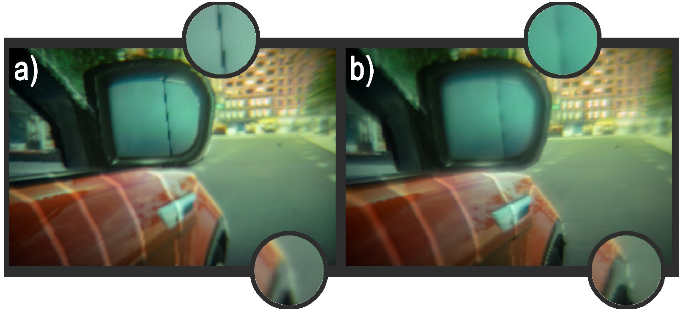
Figure 7, where a view through ocular was captured by a camera with wide-aperture (F 2.8) lens. As can be noticed from magnified insets, the focus can be changed within the scene. Furthermore, the ability to perceive a sharp content at a very close rendering distance was also confirmed, which is in support of this technique being capable of substantially mitigating VAC.
5.1. Computational Aspects for Multi-Plane 3D Rendering
When computer-generated 3D scenes are to be rendered for a multi-plane display architecture, it is quite similar to conventional stereoscopic rendering. In the first step a stereo render target is issued and a basic stereoscopic 2D texture is rendered to the intermediate buffer. Alongside with this 2D texture, a depth buffer is also output. In the following step the division into image depth planes is carried out. This procedure essentially is similar to any other post-processing shader operation, such as the application of the bloom effect or antialiasing. For the “slicing” operation, a larger output texture is created in the back buffer, the size of which typically is matched to the image resolution of the target spatial light modulator multiplied by the number of used image depth planes—thus representing full uncompressed data array for all available depth planes. Further a custom post-processing shader based on the stored depth map data remaps pixels from the rendered 2D texture to the final output texture, which when finished is output to the front buffer. With shader operations, a very efficient parallel computation can be achieved, thus making this post-processing operation brief in comparison to the initial rendering. Consequently, multi-plane stereoscopic rendering is computationally undemanding and, from practical benchmarks, we observe only up to 3% decrease in generated frames per second in comparison to basic stereoscopic rendering. It must be noted that the differences are more pronounced for simpler 3D scenes, for which the initial rendering takes less time, while for more complex scenes the differences can be virtually negligible. A more through comparison of rendering approaches and expected performance is analyzed in our previous work [
32].
Another important aspect of the “slicing” procedure, which directly impacts the end-result appearance of the visual information, is the methodology of how the content is distributed among available image depth planes. Typically, when rendering for stereoscopic displays, only the top surface is output, meaning that there is no possibility for pixels with multiple depth values. This is convenient and also ensures occlusion, though might cause some inconsistencies in very special and rare cases. Thus, the rendered pixels can have a semi-continuous range of depth values, while the display device based on its optical design has a limited discrete number of depth planes. The simplest way data can be distributed among the discrete number of image depth planes is shown in
Figure 8a. Here, a reciprocal depth space or optical space, the axis of which is measured in diopters, is shown. The vertical purple lines represent positions of focal planes, grey dotted lines represent midpoints between adjacent focal planes, whereas blue dotted lines mark absolute boundaries for the content, which can be surely displayed on a device with given arrangement of focal planes. The far boundary at 0 D corresponds to infinity is a self-explanatory boundary, whereas the near boundary can coincide with the focal plane or typically it can be displaced closer towards the eye. The amount of displacement depends on the allowable VAC that would inherently arise, and typically it is set up to 0.3 D in front of the closest focal plane, though it is suggested that at close accommodation distances, even up to 0.6 D, VAC could be entirely tolerable [
3]. When a 3D scene is considered (corresponds to the blue figure in
Figure 8a,b), it can span over all depth space. The simplest way of how to “slice” the part, that falls within the limits displayable by the multi-focal AR device, is depicted by green arrows (
Figure 8a)—pixels belonging to a region of depth space between the two closest midpoints or a midpoint and extreme boundary are allocated onto a corresponding image depth plane. As this approach excludes any overlapping pixels, even in a head-mounted display situation, in practice the boundary lines can be noticeable. This can be seen in
Figure 9b, where this principle is used for multi-plane image rendering. Typically, the effect is observed on slanting surfaces and objects and is perceived as a visual artefact degrading the perceived image quality. On one hand the effect would not be as noticeable, if higher physical discretization of the depth space could be obtained. On the other hand, this is easily mitigated by interplane antialiasing (depth blending).
The approach for interplane antialiasing is depicted in
Figure 8b. The general setting is similar as with example of
Figure 8a—the only difference is that the depth region allocated to each physical depth plane is expanded. Even a slight overlapping by depicting single pixel information on two image depth planes (optical diffuser elements) can yield noticeable improvements. Nevertheless, quite obviously, there are no reasons to expand this depth region beyond positions of adjacent focal planes. The particular example of
Figure 8b considers expansion of depth allocation region to neighboring focal planes, thus ensuring full depth antialiasing for every pixel that falls within the interplane space. Furthermore, when a pixel is output onto two focal planes, the corresponding values have to be attenuated not to exceed the native value (brightness).
It has been found that a very good results are ensured by simple linear blending algorithm, where based on the pixel’s position in the interplane space its intensity is divided among the adjacent focal planes [
14,
15]. For example, if the pixel falls exactly in the midpoint, 50% of its intensity is shown on both nearest image focal planes, whereas if it is displaced from the midpoint, it will be depicted with higher intensity on the closer focal plane. Nevertheless, the blending algorithm which determines in what proportions the intensity is distributed among focal planes based on the location of pixels can be arbitrary; it has been found that deviations from the linear approach can provide slight benefits [
18]. In practice when linear interplane antialiasing is used, the image appears to be smooth without any noticeable discontinuities. This has been shown in
Figure 9c. The slight banding that can be observed in this case at the interplane boundaries is associated to a non-linear response of the physical image source. To overcome this, a calibration has to be performed and additional scaling factors introduced. For comparison, the same content has been rendered on a single focal plane that corresponds to the basic stereoscopic way of image representation (
Figure 9a). It can be seen that with interplane antialiasing, identical image quality to basic stereoscopic rendering can be achieved with an important exception of supported monocular focus cues (see
Figure 7).
5.2. Comparison to Alternative Multifocal Approaches
In general, multifocal displays can be categorized by means, of how the focal planes are generated. In this regard screen-based or lens-based systems can be distinguished. In screen-based systems, there are either a reciprocating screen or multiple screens which optically are located at different distances. On the contrary, lens-based systems typically have a fixed image source—either a single screen or spatial light modulator—and the focal length is varied by active optical elements, thus these types of displays are also inclusive of systems utilizing alternative optical components for the focal-length modulation.
A variant of screen-based system in the laboratory environment has been used by Akeley [
14]. In this work a three-focal plane stereoscopic display prototype was constructed by segmenting a high-resolution LCD display into three portions. Angled beam splitters were used to align all screens on a single optical path. Nevertheless, from a practical point of view, this is an inefficient way of synthesizing focal planes, as beam-splitters attenuate a large portion of light, which is decreased even further when considering inefficiency of optical image combiners required by the AR design. Alternatively, transparent displays have been anticipated to be a viable solution—in particular transparent OLED displays, which would allow dense and compact stacking avoiding utilization of beam-splitters [
34]. Nevertheless, this has not resulted in a practical design, as ultra-high transparency was not ensured, and typically these display panels exhibited haze that is not practical for multi-layer stacking. The distinguishing characteristic of these two examples is that they do not require time multiplexing and all image focal planes could be shown simultaneously, thus improving image brightness. The solution by LightSpace also falls into the same display category with ultra-transparent low-haze optical diffuser elements (screens) overcoming stacking issue and light loss attributed to utilizing beam-splitters. In contrast this approach requires time multiplexing; nevertheless, switching characteristics of diffuser elements allow for obtaining image refresh rates that surpass the flicker perception threshold when a reasonable number of focal planes are used (3–16). Thus, the image source (spatial light modulator) becomes the limiting link in the reproduction of the image.
In lens-based systems it is possible to distinguish optical elements that change their optical strength continuously and systems with discrete states. In case of optical elements with discrete states, which can include optical length modulators, birefringent lenses, and liquid-crystal lenses, the number of maximum image planes is limited. On one hand, to obtain multiple focal lengths these elements have to be stacked, which attenuates the overall light intensity, while on the other hand, on separate occasions it is limited by the switching time, which can be in the order of milliseconds. In contrast, continuously-tunable liquid lenses and electrostatically-deformable mirrors are optically more efficient and allow for an arbitrary number of focal planes. Nevertheless, often the settling time for a liquid focus-tunable lens is substantially high (5–10 ms), which is inhibitive of high image refresh rates. The alternative proposed by J.-H.R. Chang utilizes a liquid-tunable lens in conjunction with a real-time focus tracking system, meaning that the focal length is scanned continuously and there is no need to wait for the lens to settle [
19]. As a consequence, this shifts the role of the limiting link from the lens to the image source (spatial light modulator). Nevertheless, continuously scanning systems, whether lens-based or screen-based (mechanically reciprocating screen), have limitations associated to image brightness and sharpness (focal smear). To precisely define the focal depth, from which the given information is originating, it is desirable to illuminate a given frame for a period as short as possible, thus challenging the response time of a screen/spatial light modulator and resulting in a dim overall image, which is not suitable for AR applications. Things become even more severe if the field sequential principle of color representation is to be used—meaning that inherently different color subframes are originating from different focal distances, causing color fringes (analog to chromatic aberrations). In light of this, it is obvious, that practical designs of multifocal display architecture that are suitable for AR applications are extremely challenging. Nevertheless, there are no principle limitations that would inhibit a practical design of an AR display system based on optical diffuser technology by LightSpace Technologies.
5.3. Implementation of the Core Volumetric Technology into an AR Device
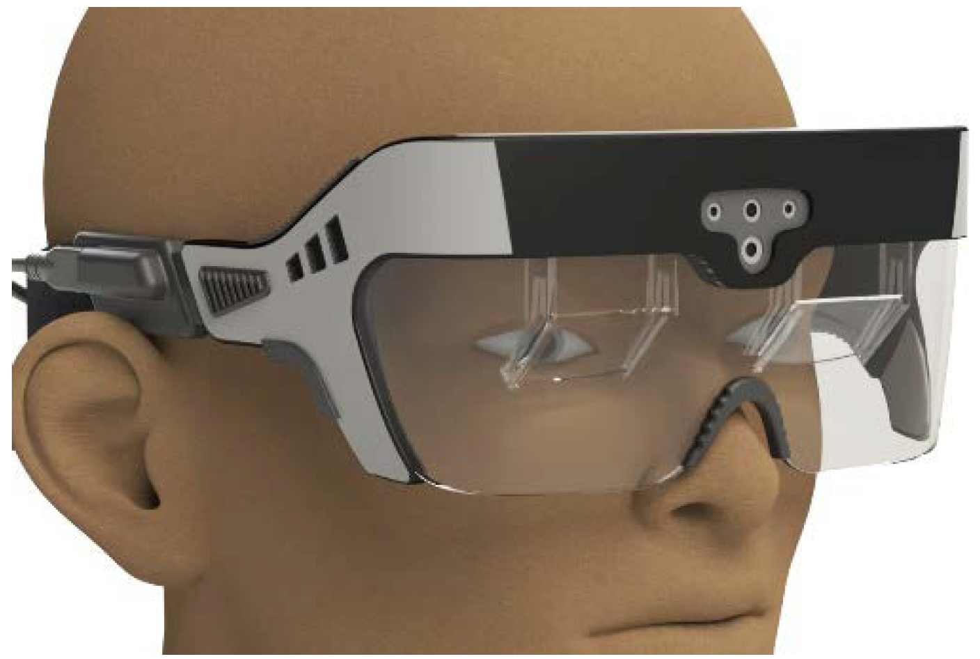
Based on our testing results of the VR proof-of-concept prototype system, further steps involve implementation of the proposed multifocal display architecture within an augmented reality wearable display, which will allow real-world multifocal display testing to be performed from human performance and practicality points of view. Our preliminary evaluation indicates the ability to yield a compact footprint headset using a conventional beam-splitter optical image combiner and custom design parts. The attainable footprint can be evaluated from
Figure 10, which shows a computer aided design (CAD) model that is based on realistic hardware parameters. As we primarily are concerned with near-work performance, optimization is aimed towards improved image resolution at the expense of horizontal field-of-view.
Overall it must be said that, regardless of type of the next-generation display technology, performance of current spatial light modulators is an important limiting factor constraining image performance. For a wider field-of-view, not just optics provide limits, but very much resolution of spatial light modulators as well. On one hand, there are microdisplays (LCD and OLED type), which can yield high image resolutions but still their footprint, image refresh rate, and brightness are not well suited for the next-generation AR displays. A solution, possibly facilitating emergence of discussed display technologies, might be solid-state LED microdisplays, promising a compact footprint, very high brightness, and a competitive image refresh rate. Nevertheless, µLED displays are also only maturing and will not become readily available for at least several years. With this in mind, reflective-type SLMs, such as DMDs and LCoS (Liquid Crystal on Silicon), are best suited for next-generation displays. Moreover, DMD performance has not reached fundamental limit, but rather is related to driving electronics, meaning that increased interest in wearable display technologies could be a good motivation for emergence of new, faster, more integrated, compact footprintreflective SLMs, opening a whole new world for VAC-corrected displays.
6. Summary
We briefly overviewed the current state and trends in 3D stereoscopic wearable displays. It has become generally accepted that the vergence–accommodation conflict is one of the major hindering factors limiting wide acceptance and commercial success of stereoscopic head-mounted display systems, and that solutions have to be found and introduced as fast as possible. An ultimate solution to this is foreseen to be a holographic-type display, but while it still too challenging for practical implementation and commercialization, alternative methods, also offering corrected VAC and monocular focus cues, have been proposed. Among these methods, multifocal wearable displays are expected to be the most promising and commercialized first.
LightSpace Technologies have proposed a multifocal display solution based on a volumetric display architecture. At the core of the proposition is an ultra-fast response time liquid-crystal optical diffuser element, which, when stacked, forms a projection volume. By using an ultra-fast image-projection microunit and synchronizing image output with an optical state of the projection volume, image depth planes can be output in a time-multiplexed manner at a very high rate surpassing the flicker fusion frequency. Coupling an eyepiece optic to the projection volume demultiplexes different virtual image depth planes expanded over all usable depth space. This is perceived as a depth-discretized space allowing the user to refocus. By implementing four to six image depth planes and utilizing depth blending, the accommodation of the viewer can be driven virtually continuously. The core technology is highly scalable and, when coupled with conventional beam-splitter-based optical image combiners, can result in a compact competitive footprint of the device. As a proof-of-concept, a virtual reality head-mounted display system based on six image depth planes was demonstrated, yielding 72° horizontal field-of-view, 6 cpd resolution, and VAC-corrected accommodative range of 3.2 D. A further actual design of an AR wearable system based on optimized component size and conventional beam-splitter-based image combiner has was developed. Still, as with all current next-generation 3D display technologies, the important limiting factor directly impacting basic image characteristics (resolution, field-of-view, refresh rate) remains the capabilities of available spatial light modulators. For next-generation 3D display technologies to really become competitive, spatial light modulators with improved resolution, small footprint containing low-power-integrated electronics, and ensuring response times as low as possible are required. The progress in this regard is slow but not principally impossible to achieve substantial advancements, at least in some aspects of SLM technologies.


