Discrete-Time Fractional Order Integral Sliding Mode Control of an Antagonistic Actuator Driven by Pneumatic Artificial Muscles


Abstract
1. Introduction
2. System Description
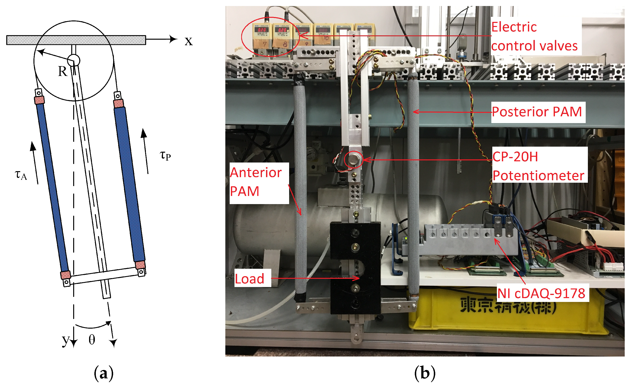
2.1. Experiment Platform
2.2. System Modeling
- Step 1:
- The initial position of the actuator was set at by supplying nominal pressure to each PAMs of the actuator.
- Step 2:
- The actuator angle can be changed by sending different types of control signal to the electrical control valves. Three types of control signals were used in this experiment:
- Step response: the control signal was a step wave with the final values 0.2, 0.4, 0.5, and 0.8 MPa.
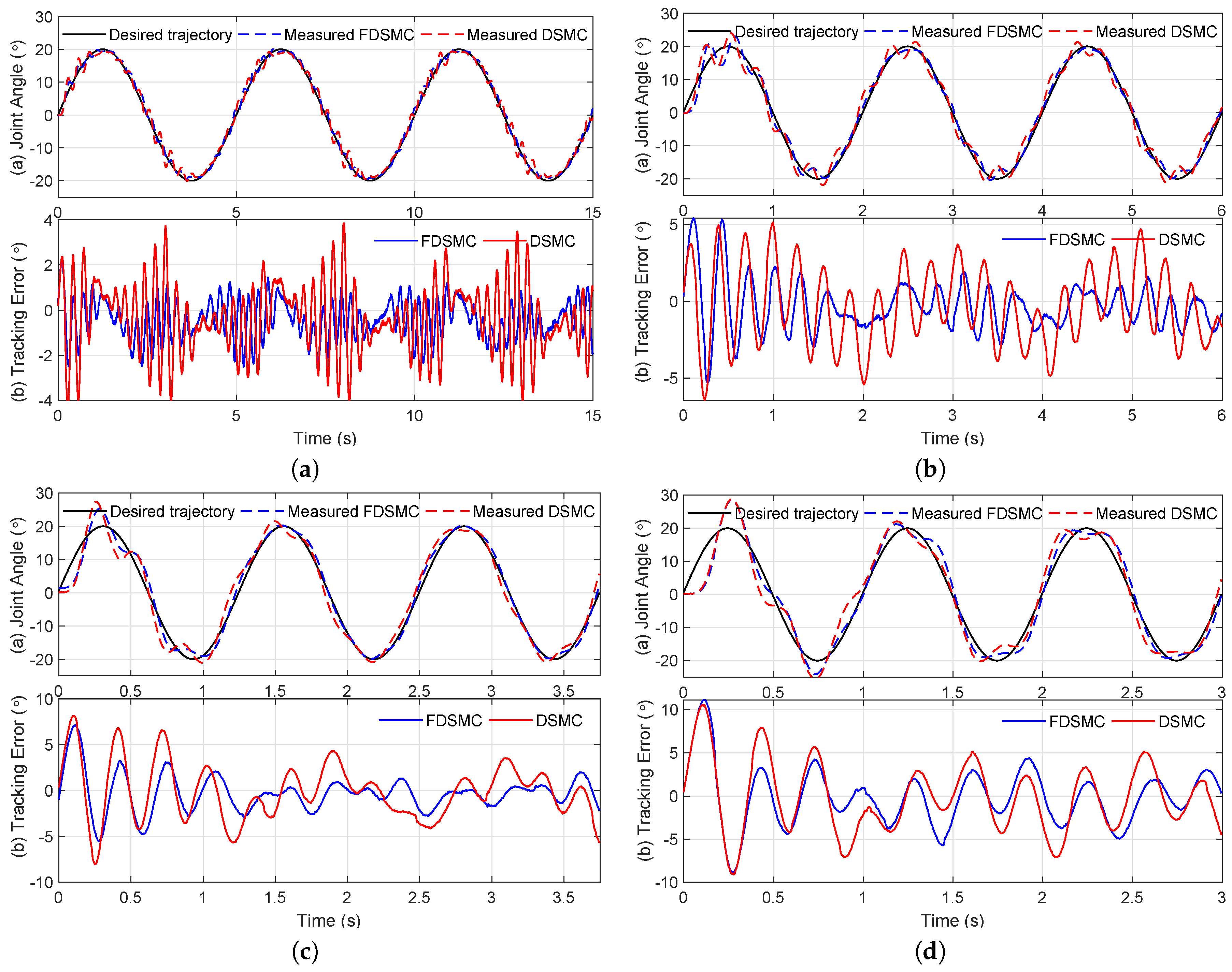
- Sinusoidal signal: The control signal is the 0.2 MPa amplitude sinusoidal signal, where frequency varies from 0.2 to 1.0 Hz.
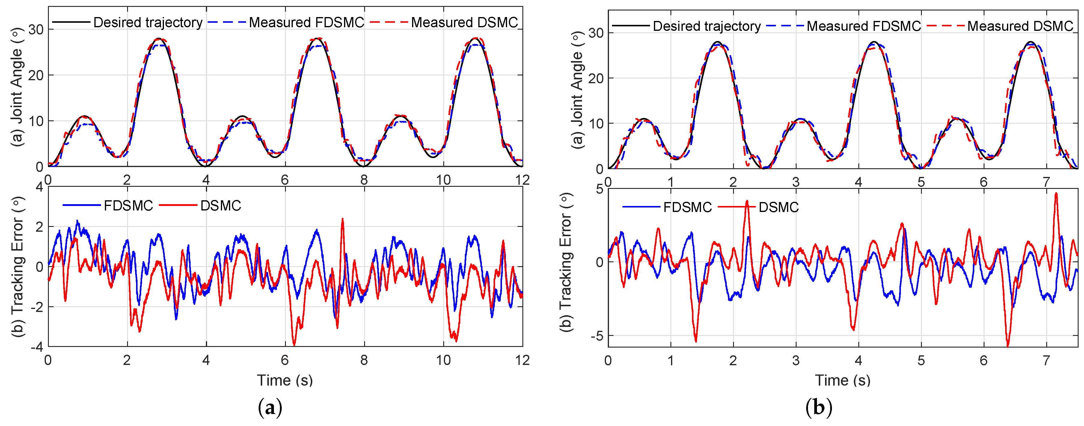
- A sine wave signal with time-varying amplitude and frequency, as in the following equation:where MPa and Hz are the basis amplitude and frequency of the control signal, respectively.
All the data, including control signals and measured angles of actuator, were recorded with sampling time = 5 ms for further analysis. - Step 3:
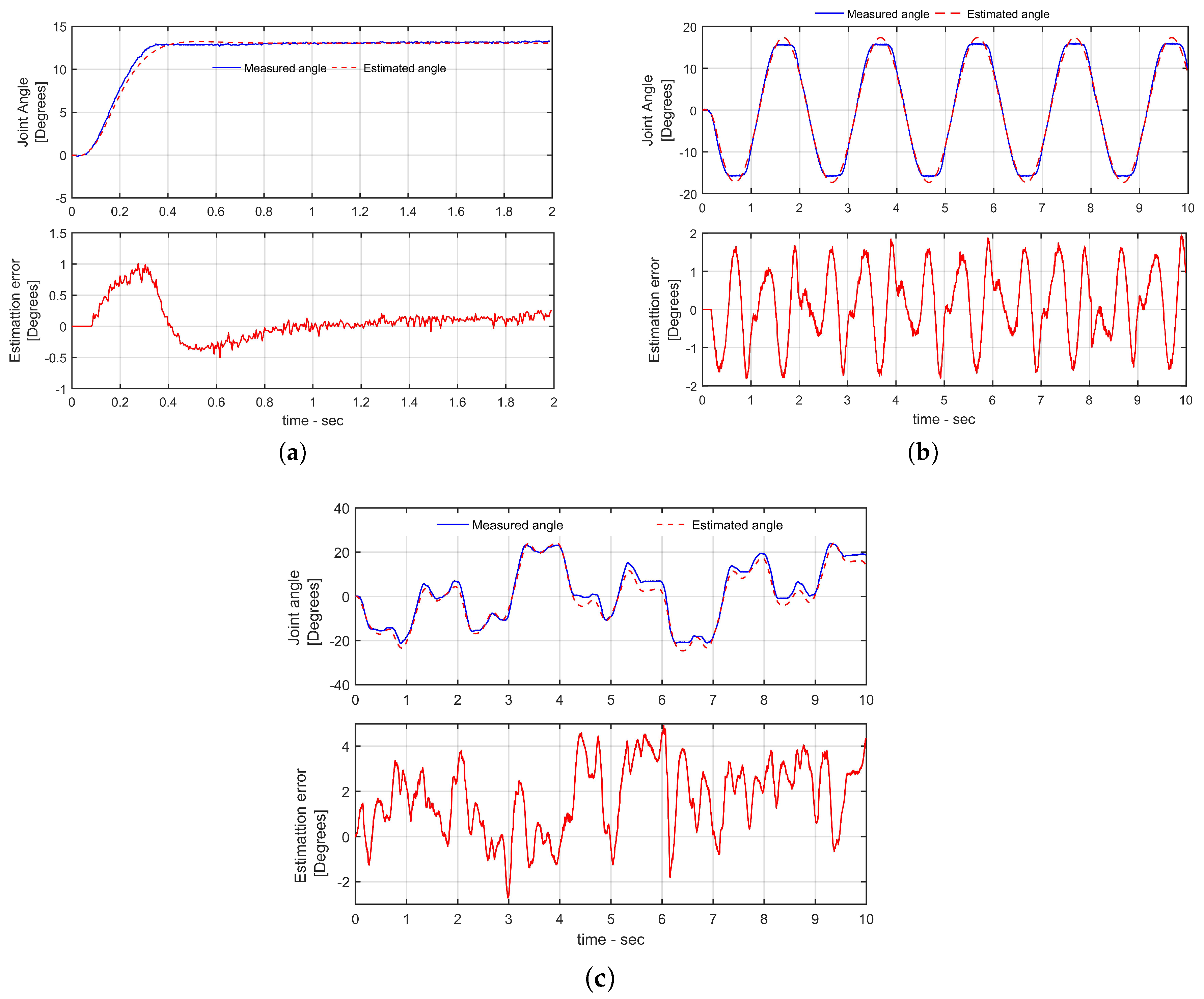
- The discrete-time SOPDT, in which , was chosen as the mathematical model of the actuator with good accuracy. The precise values of the model’s parameters are estimated by using the MATLAB software and provided in Table 2.
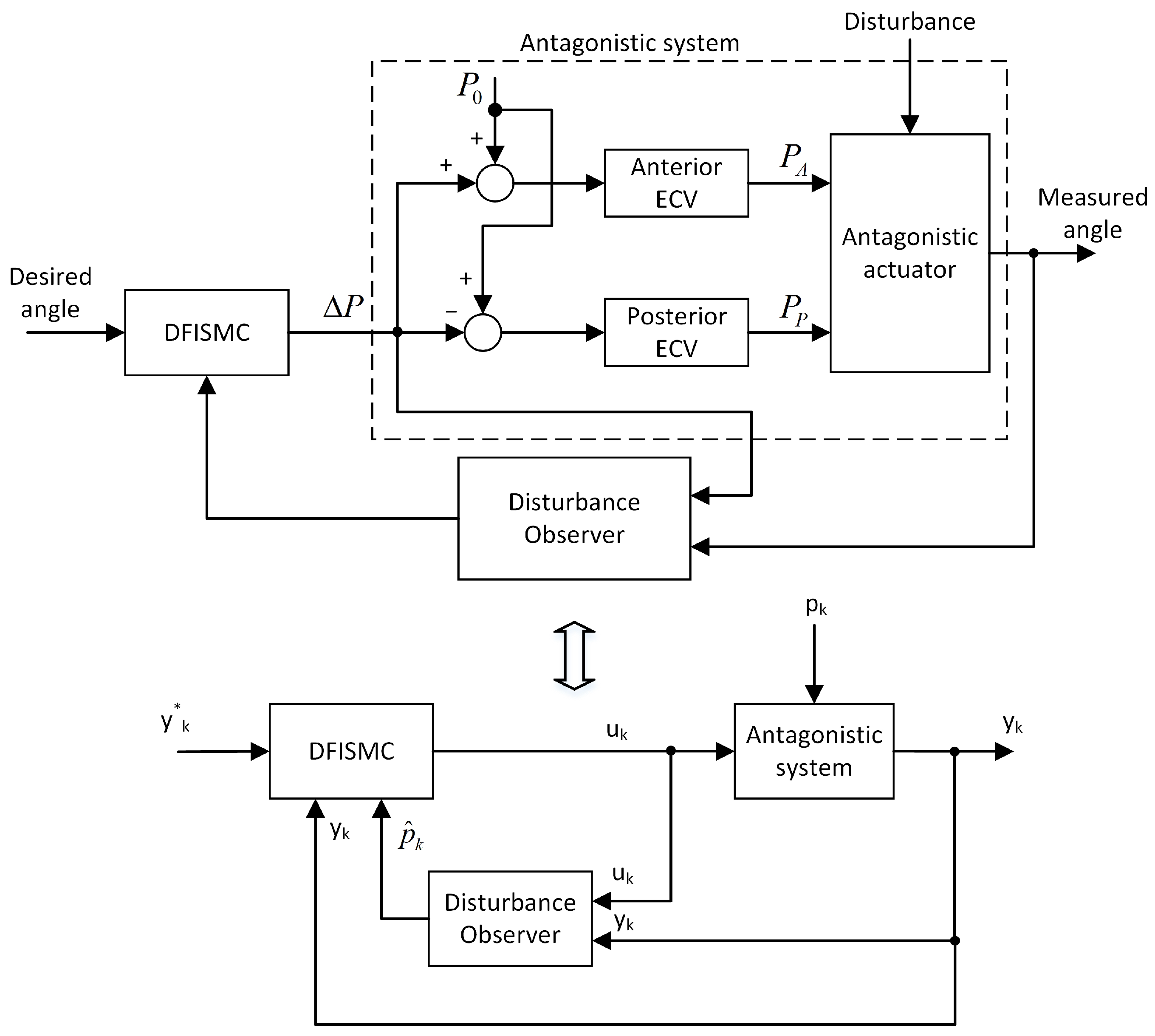
3. Control Design
4. Experimental Evaluation
4.1. Experimental Procedure
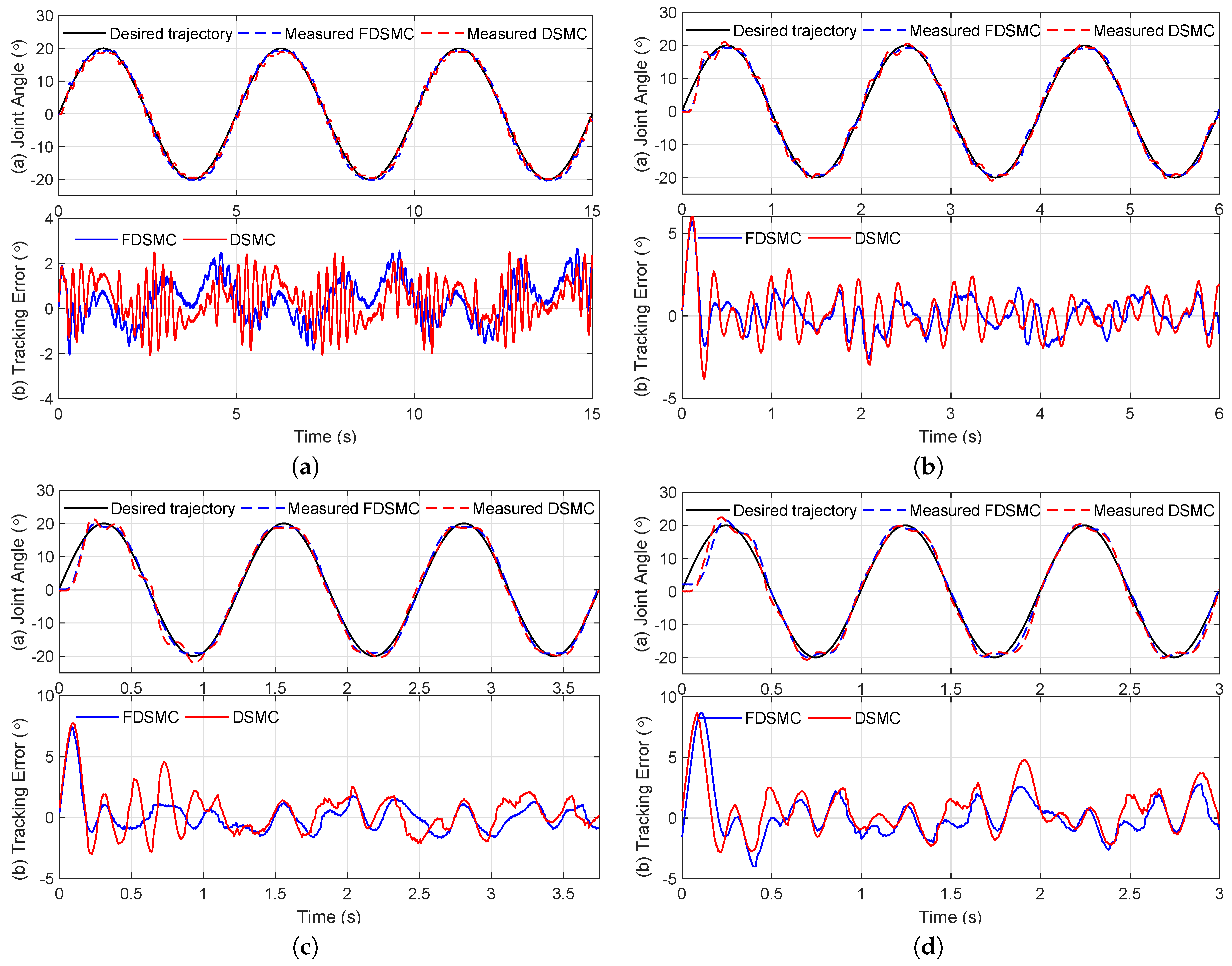
4.2. Experiment Result
5. Discussion and Conclusions
Author Contributions
Conflicts of Interest
Abbreviations
| PAM | Pneumatic artificial muscle |
| PID | Proportional integral derivative |
| SOPDT | Second order plus dead time |
| SISO | Single input single output |
| SMC | Sliding mode control |
| DSMC | Discrete-time sliding mode control |
| DFISMC | Discrete-time fractional order integral sliding mode control |
| MTE | Maximum tracking error |
| RMSTE | Root mean square tracking error |
| ESO | Extended state observer |
| ADRC | Active disturbance rejection controller |
| DSO | Disturbance observe |
| SD | Standard deviation |
| FOI | Fractional order integral |
| GC | Gait cycle |
Appendix A. Fractional Integral Approximation
Appendix B. Proof of Assumption 1
References
- Banala, S.K.; Kim, S.H.; Agrawal, S.K.; Scholz, J.P. Robot Assisted Gait Training with Active Leg Exoskeleton (ALEX). IEEE Trans. Neural Syst. Rehabil. Eng. 2009, 17, 2–8. [Google Scholar] [CrossRef]
- Beyl, P.; Knaepen, K.; Duerinck, S.; Van Damme, M.; Vanderborght, B.; Meeusen, R.; Lefeber, D. Safe and Compliant Guidance by a Powered Knee Exoskeleton for Robot-Assisted Rehabilitation of Gait. Adv. Robot. 2011, 25, 513–535. [Google Scholar] [CrossRef]
- Dao, Q.-T.; Yamamoto, S.-I. Assist-as-Needed Control of a Robotic Orthosis Actuated by Pneumatic Artificial Muscle for Gait Rehabilitation. Appl. Sci. 2018, 8, 499. [Google Scholar] [CrossRef]
- Hussain, S.; Xie, S.Q.; Jamwal, P.K. Control of a robotic orthosis for gait rehabilitation. Robot. Auton. Syst. 2013, 61, 911–919. [Google Scholar] [CrossRef]
- Reynolds, D.B.; Repperger, D.W.; Phillips, C.A.; Bandry, G. Dynamic characteristics of pneumatic muscle. Ann. Biomed. Eng. 2003, 31, 310–317. [Google Scholar] [CrossRef]
- Xing, K.; Huang, J.; Wang, Y.; Wu, J.; Xu, Q.; He, J. Tracking control of pneumatic artificial muscle actuators based on sliding mode and non-linear disturbance observer. IET Control Theory Appl. 2010, 4, 2058–2070. [Google Scholar] [CrossRef]
- Lilly, J.H.; Quesada, P.M. A two-input sliding-mode controller for a planar arm actuated by four pneumatic muscle groups. IEEE Trans. Neural Syst. Rehabil. Eng. 2004, 12, 349–359. [Google Scholar] [CrossRef]
- Lilly, J.H.; Yang, L. Sliding mode tracking for pneumatic muscle actuators in opposing pair configuration. IEEE Trans. Control Syst. Technol. 2005, 13, 550–558. [Google Scholar] [CrossRef]
- Choi, T.Y.; Lee, J.J. Control of Manipulator Using Pneumatic Muscles for Enhanced Safety. IEEE Trans. Ind. Electron. 2010, 57, 2815–2825. [Google Scholar] [CrossRef]
- Choi, T.Y.; Choi, B.S.; Seo, K.H. Position and Compliance Control of a Pneumatic Muscle Actuated Manipulator for Enhanced Safety. IEEE Trans. Control Syst. Technol. 2011, 19, 832–842. [Google Scholar] [CrossRef]
- Hussain, S.; Xie, S.Q.; Jamwal, P.K. Adaptive Impedance Control of a Robotic Orthosis for Gait Rehabilitation. IEEE Trans. Cybern. 2013, 43, 1025–1034. [Google Scholar] [CrossRef]
- Merola, A.; Colacino, D.; Cosentino, C.; Amato, F. Model-based tracking control design, implementation of embedded digital controller and testing of a biomechatronic device for robotic rehabilitation. Mechatronics 2018, 52, 70–77. [Google Scholar] [CrossRef]
- Minh, T.V.; Tjahjowidodo, T.; Ramon, H.; Brussel, H.V. Cascade position control of a single pneumatic artificial muscle-mass system with hysteresis compensation. Mechatronics 2010, 20, 402–414. [Google Scholar] [CrossRef]
- Xie, S.; Mei, J.; Liu, H.; Wang, Y. Hysteresis modeling and trajectory tracking control of the pneumatic muscle actuator using modified Prandtl—Ishlinskii model. Mech. Mach. Theory 2018, 120, 213–224. [Google Scholar] [CrossRef]
- Kosaki, T.; Minesaki, A.; Sano, M. Adaptive Hysteresis Compensation with a Dynamic Hysteresis Model for Control of a Pneumatic Muscle Actuator. J. Environ. Eng. 2012, 7, 53–65. [Google Scholar] [CrossRef][Green Version]
- Vo-Minh, T.; Tjahjowidodo, T.; Ramon, H.; Brussel, H.V. A new approach to modeling hysteresis in a pneumatic artificial muscle using the Maxwell-slip model. IEEE/ASME Trans. Mechatron. 2011, 16, 177–186. [Google Scholar] [CrossRef]
- Minh, T.V.; Kamers, B.; Ramon, H.; Brussel, H.V. Modeling and control of a pneumatic artificial muscle manipulator joint- part i: Modeling of a pneumatic artificial muscle manipulator joint with accounting for creep effect. Mechatronics 2012, 22, 923–933. [Google Scholar] [CrossRef]
- Ba, D.X.; Ahn, K.K. Indirect sliding mode control based on gray-box identification method for pneumatic artificial muscle. Mechatronics 2015, 32, 1–11. [Google Scholar] [CrossRef]
- Ba, D.X.; Dinh, T.Q.; Ahn, K.K. An integrated intelligent nonlinear control method for a pneumatic artificial muscle. IEEE/ASME Trans. Mechatron. 2016, 21, 1835–1845. [Google Scholar] [CrossRef]
- Robinson, R.M.; Kothera, C.S.; Sanner, R.M.; Wereley, N.M. Nonlinear Control of Robotic Manipulators Driven by Pneumatic Artificial Muscles. IEEE/ASME Trans. Mechatron. 2016, 21, 55–68. [Google Scholar] [CrossRef]
- Cveticanin, L.; Zukovic, M.; Biro, I.; Sarosi, J. Mathematical investigation of the stability condition and steady state position of a pneumatic artificial muscle—Mass system. Mech. Mach. Theory 2018, 125, 196–206. [Google Scholar] [CrossRef]
- Yang, H.; Yu, Y.; Zhang, J. Angle tracking of a pneumatic muscle actuator mechanism under varying load conditions. Control Eng. Pract. 2017, 61, 1–10. [Google Scholar] [CrossRef]
- Zhao, L.; Li, Q.; Liu, B.; Cheng, H. Trajectory Tracking Control of a One Degree of Freedom Manipulator Based on a Switched Sliding Mode Controller with a Novel Extended State Observer Framework. IEEE Trans. Syst. Man Cybern. Syst. 2019, 49, 1110–1118. [Google Scholar] [CrossRef]
- Andrikopoulos, G.; Nikolakopoulos, G.; Manesis, S. Advanced Nonlinear PID-Based Antagonistic Control for Pneumatic Muscle Actuators. IEEE Trans. Ind. Electron. 2014, 61, 6926–6937. [Google Scholar] [CrossRef]
- Yuan, Y.; Yu, Y.; Guo, L. Nonlinear Active Disturbance Rejection Control for the Pneumatic Muscle Actuators with Discrete-Time Measurements. IEEE Trans. Ind. Electron. 2019, 66, 2044–2053. [Google Scholar] [CrossRef]
- Zhao, L.; Liu, X.; Wang, T. Trajectory tracking control for double-joint manipulator systems driven by pneumatic artificial muscles based on a nonlinear extended state observer. Mech. Syst. Signal Process. 2019, 122, 307–320. [Google Scholar] [CrossRef]
- Zhao, L.; Cheng, H.; Xia, Y.; Liu, B. Angle Tracking Adaptive Backstepping Control for a Mechanism of Pneumatic Muscle Actuators via an AESO. IEEE Trans. Ind. Electron. 2019, 66, 4566–4576. [Google Scholar] [CrossRef]
- Yuan, Y.; Yu, Y.; Wang, Z.; Guo, L. A Sampled-Data Approach to Nonlinear ESO-Based Active Disturbance Rejection Control for Pneumatic Muscle Actuator Systems with Actuator Saturations. IEEE Trans. Ind. Electron. 2019, 66, 4608–4617. [Google Scholar] [CrossRef]
- Winter, D.A. Biomechanics and Motor Control of Human Movement, 3rd ed.; University of Waterloo Press: Waterloo, ON, Canada, 1990. [Google Scholar]
- Riener, R.; Lunenburger, L.; Jezernik, S.; Anderschitz, M.; Colombo, G.; Dietz, V. Patient-cooperative strategies for robot-aided treadmill training: First experimental results. IEEE Trans. Neural Syst. Rehabil. Eng. 2005, 13, 380–394. [Google Scholar] [CrossRef]
- Nguyen, M.L.; Chen, X. Discrete-Time Fractional Order Integral Sliding Mode Control for Piezoelectric Actuators with Improved Performance Based on Fuzzy Tuning. In Proceedings of the 2018 13th World Congress on Intelligent Control and Automation (WCICA), Changsha, China, 4–8 July 2018; pp. 554–559. [Google Scholar] [CrossRef]


| Parameters | [MPa] | ||
|---|---|---|---|
| Values | 22 | 15 | 0.2 |
| Model Parameters | d | ||||
|---|---|---|---|---|---|
| Value (Mean ± SD) | −1.9139 ± 0.0182 | 0.9164 ± 0.0180 | 0.0472 ± 0.0064 | 0.0460 ± 0.0061 | 22 ± 3 |
| Parameters | FDISMC | DSMC | ||
|---|---|---|---|---|
| Values | 0.8 | 0.01 | 0.1 | |
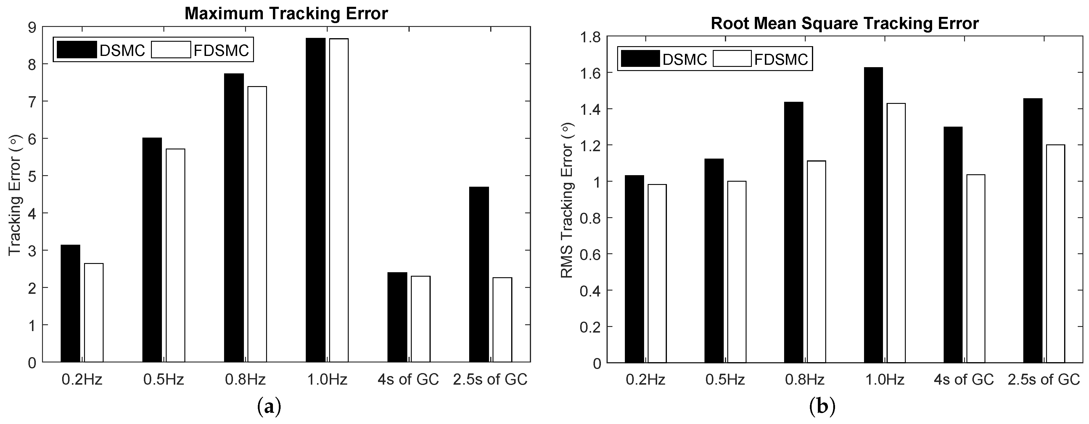
| Signal Frequency | MTE () | RMSTE () | ||
|---|---|---|---|---|
| DSMC | DFISMC | DSMC | DFISMC | |
| 0.2 Hz | 3.14 | 2.65 | 1.03 | 0.98 |
| 0.5 Hz | 6.01 | 5.71 | 1.12 | 1.00 |
| 0.8 Hz | 7.73 | 7.39 | 1.43 | 1.11 |
| 1.0 Hz | 8.68 | 8.67 | 1.63 | 1.43 |
| 4 s of GC | 2.40 | 2.31 | 1.30 | 1.04 |
| 2.5 s of GC | 4.69 | 2.26 | 1.45 | 1.20 |
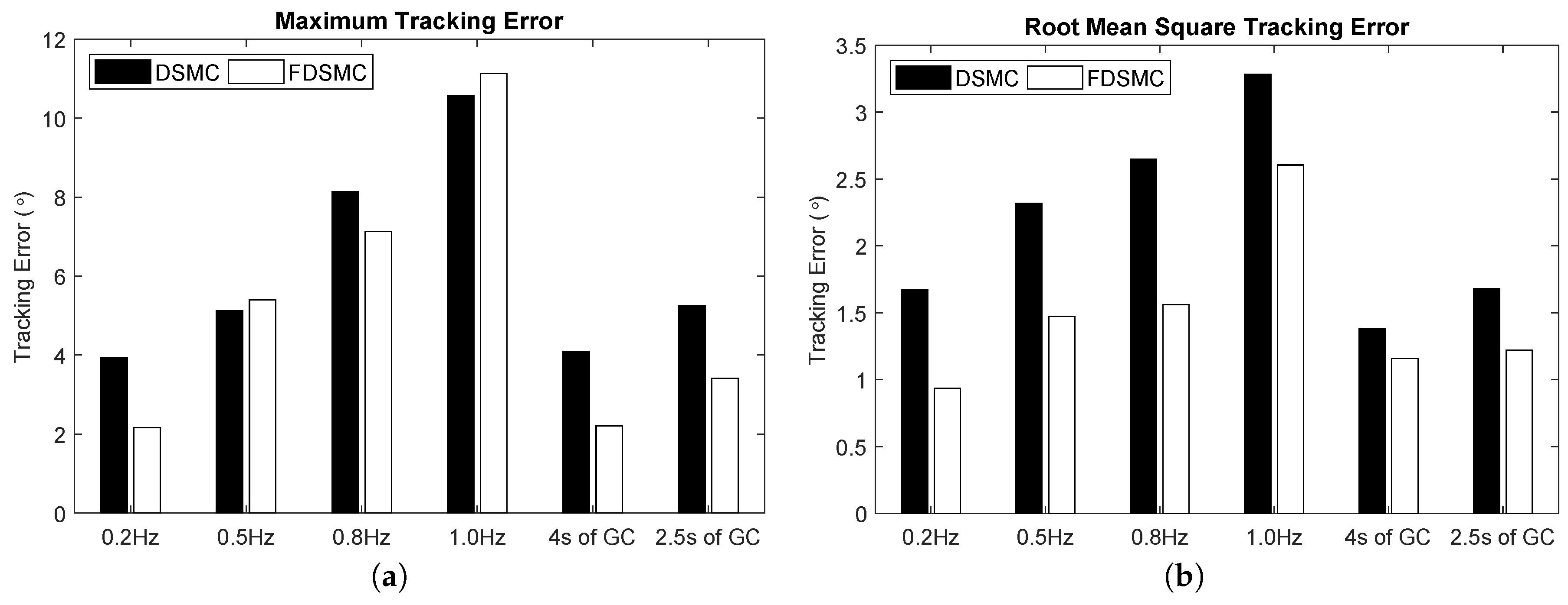
| Signal Frequency | MTE () | RMSTE () | ||
|---|---|---|---|---|
| DSMC | DFISMC | DSMC | DFISMC | |
| 0.2 Hz | 3.94 | 2.16 | 1.67 | 0.93 |
| 0.5 Hz | 5.11 | 5.39 | 2.31 | 1.47 |
| 0.8 Hz | 8.13 | 7.13 | 2.64 | 1.56 |
| 1.0 Hz | 10.56 | 11.13 | 3.28 | 2.61 |
| 4 s of GC | 4.09 | 2.20 | 1.38 | 1.16 |
| 2.5 s of GC | 5.23 | 3.41 | 1.68 | 1.22 |
© 2019 by the authors. Licensee MDPI, Basel, Switzerland. This article is an open access article distributed under the terms and conditions of the Creative Commons Attribution (CC BY) license (http://creativecommons.org/licenses/by/4.0/).
Share and Cite
Dao, Q.-T.; Nguyen, M.-L.; Yamamoto, S.-i. Discrete-Time Fractional Order Integral Sliding Mode Control of an Antagonistic Actuator Driven by Pneumatic Artificial Muscles. Appl. Sci. 2019, 9, 2503. https://doi.org/10.3390/app9122503
Dao Q-T, Nguyen M-L, Yamamoto S-i. Discrete-Time Fractional Order Integral Sliding Mode Control of an Antagonistic Actuator Driven by Pneumatic Artificial Muscles. Applied Sciences. 2019; 9(12):2503. https://doi.org/10.3390/app9122503
Chicago/Turabian StyleDao, Quy-Thinh, Manh-Linh Nguyen, and Shin-ichiroh Yamamoto. 2019. "Discrete-Time Fractional Order Integral Sliding Mode Control of an Antagonistic Actuator Driven by Pneumatic Artificial Muscles" Applied Sciences 9, no. 12: 2503. https://doi.org/10.3390/app9122503
APA StyleDao, Q.-T., Nguyen, M.-L., & Yamamoto, S.-i. (2019). Discrete-Time Fractional Order Integral Sliding Mode Control of an Antagonistic Actuator Driven by Pneumatic Artificial Muscles. Applied Sciences, 9(12), 2503. https://doi.org/10.3390/app9122503