Electrical and Mechanical Properties of Ink Printed Composite Electrodes on Plastic Substrates


Abstract
Featured Application
Abstract
1. Introduction
2. Materials and Methods
2.1. Materials
2.2. Preparation of Composite Inks
2.3. Inkjet Printing of Composite Electrodes and Low Temperature Sintering
2.4. Characterization
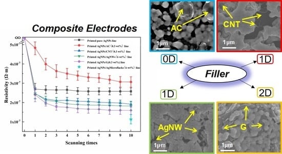
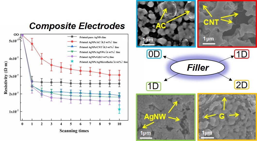
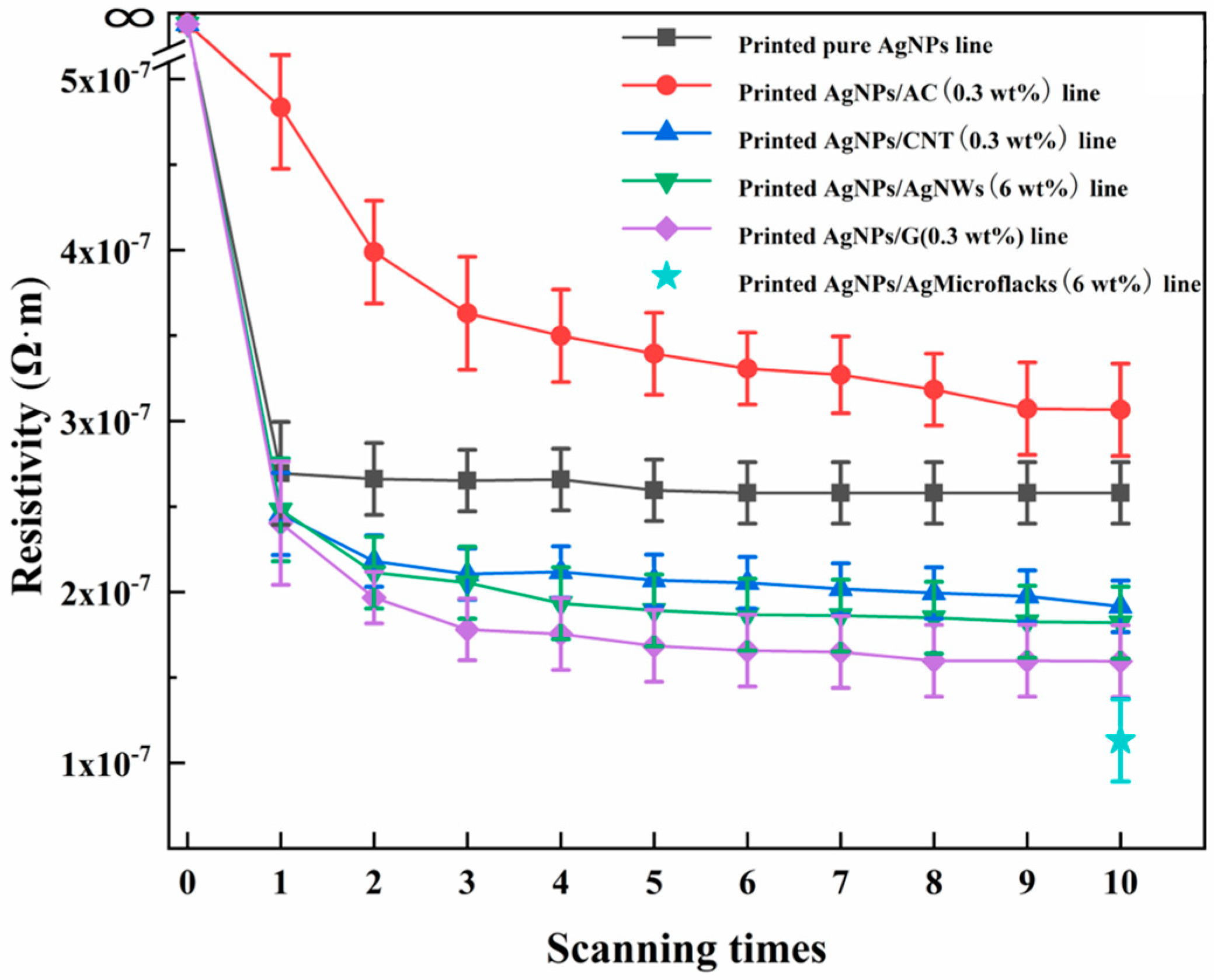
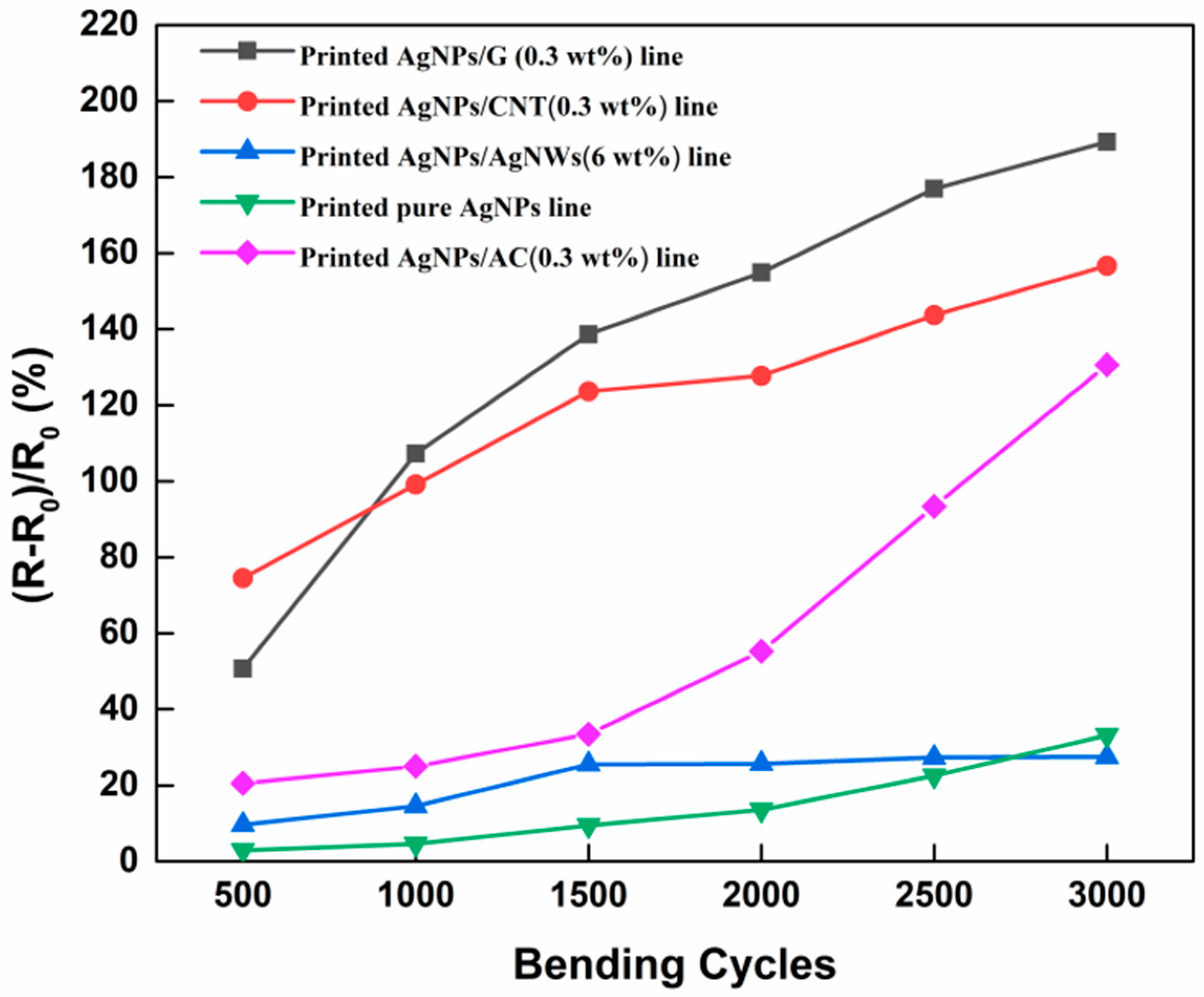
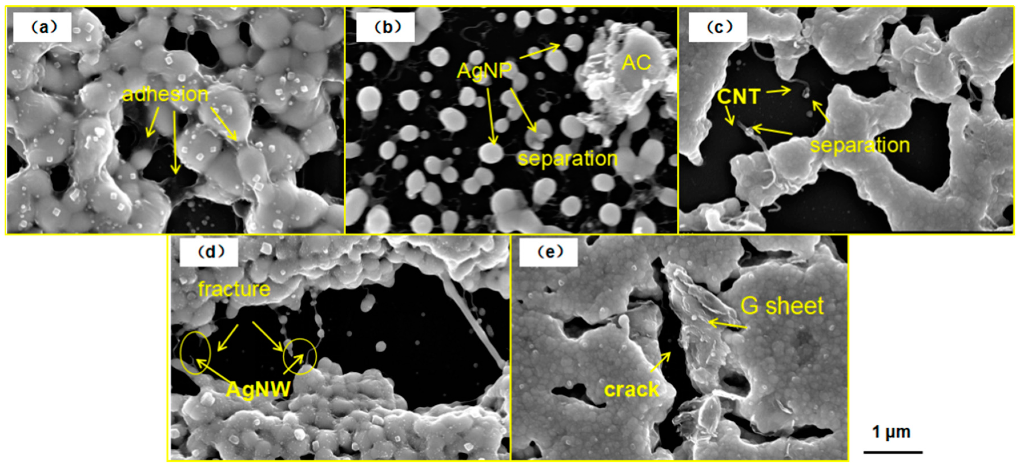
3. Results and Discussion
4. Conclusions
Author Contributions
Funding
Conflicts of Interest
References
- Abbel, R.; Teunissen, P.; Michels, J.; Groen, W.A. Narrow Conductive Structures with High Aspect Ratios Through Single-Pass Inkjet Printing and Evaporation-Induced Dewetting. Adv. Eng. Mater. 2015, 17, 615–619. [Google Scholar] [CrossRef]
- Kim, C.; Nogi, M.; Suganuma, K.; Yamato, Y. Inkjet-printed lines with well-defined morphologies and low electrical resistance on repellent pore-structured polyimide films. ACS Appl. Mater. Interfaces 2012, 4, 2168–2173. [Google Scholar] [CrossRef] [PubMed]
- Hoeng, F.; Denneulin, A.; Reverdy-Bruas, N.; Krosnicki, G.; Bras, J. Rheology of cellulose nanofibrils/silver nanowires suspension for the production of transparent and conductive electrodes by screen printing. Appl. Surf. Sci. 2017, 394, 160–168. [Google Scholar] [CrossRef]
- Shiokawa, D.; Izumi, K.; Sugano, R.; Sekine, T.; Minami, T.; Kumaki, D.; Tokito, S. Development of a silver nanoparticle ink for fine line patterning using gravure offset printing. Jpn. J. Appl. Phys. 2017, 56, 05EA04. [Google Scholar] [CrossRef]
- Zhao, D.; Liu, T.; Park, J.G.; Zhang, M.; Chen, J.-M.; Wang, B. Conductivity enhancement of aerosol-jet printed electronics by using silver nanoparticles ink with carbon nanotubes. Microelectron. Eng. 2012, 96, 71–75. [Google Scholar] [CrossRef]
- Zhang, Y.; Li, X.; Mou, X.; Li, N. Preparation and Performance of Edible Screen-Printing Ink with Chitosan. In Advanced Graphic Communications, Packaging Technology and Materials; Springer: Singapore, 2016; pp. 977–983. [Google Scholar]
- Zhang, J.; Li, X.; Shi, X.; Hua, M.; Zhou, X.; Wang, X. Synthesis of core–shell acrylic–polyurethane hybrid latex as binder of aqueous pigment inks for digital inkjet printing. Prog. Natl. Sci. Mater. Int. 2012, 22, 71–78. [Google Scholar] [CrossRef]
- Tai, J.L.; Chen, G.X.; Chen, Q.F.; Tang, B.L. Study on Polyurethane-Acrylic Hybrid Emulsion Applying to Water-Based Ink. Appl. Mech. Mater. 2012, 182–183, 3–7. [Google Scholar] [CrossRef]
- Dimic-Misic, K.; Gane, P.A.C.; Paltakari, J. Micro- and Nanofibrillated Cellulose as a Rheology Modifier Additive in CMC-Containing Pigment-Coating Formulations. Ind. Eng. Chem. Res. 2013, 52, 16066–16083. [Google Scholar] [CrossRef]
- Lu, Z.; Jiang, X.; Zuo, X.; Feng, L. Improvement of cytocompatibility of 3D-printing resins for endothelial cell adhesion. RSC Adv. 2016, 6, 102381–102388. [Google Scholar] [CrossRef]
- Hu, G.; Kang, J.; Ng, L.W.T.; Zhu, X.; Howe, R.C.T.; Jones, C.G.; Hersam, M.C.; Hasan, T. Functional inks and printing of two-dimensional materials. Chem. Soc. Rev. 2018, 47, 3265–3300. [Google Scholar] [CrossRef] [PubMed]
- Peng, P.; Hu, A.; Zhou, Y. Laser sintering of silver nanoparticle thin films: Microstructure and optical properties. Appl. Phys. A 2012, 108, 685–691. [Google Scholar] [CrossRef]
- Ko, S.H.; Pan, H.; Grigoropoulos, C.P.; Luscombe, C.K.; Fréchet, J.M.J.; Poulikakos, D. All-inkjet-printed flexible electronics fabrication on a polymer substrate by low-temperature high-resolution selective laser sintering of metal nanoparticles. Nanotechnology 2007, 18, 345202. [Google Scholar] [CrossRef]
- Cheng, Y.-T.; Uang, R.-H.; Chiou, K.-C. Effect of PVP-coated silver nanoparticles using laser direct patterning process by photothermal effect. Microelectron. Eng. 2011, 88, 929–934. [Google Scholar] [CrossRef]
- Derby, B. Inkjet Printing of Functional and Structural Materials: Fluid Property Requirements, Feature Stability, and Resolution. Ann. Rev. Mater. Res. 2010, 40, 395–414. [Google Scholar] [CrossRef]
- Hu, G.; Albrow-Owen, T.; Jin, X.; Ali, A.; Hu, Y.; Howe, R.C.T.; Shehzad, K.; Yang, Z.; Zhu, X.; Woodward, R.I.; et al. Black phosphorus ink formulation for inkjet printing of optoelectronics and photonics. Nat. Commun. 2017, 8, 278. [Google Scholar] [CrossRef] [PubMed]
- Huang, X.; Leng, T.; Zhang, X.; Chen, J.C.; Chang, K.H.; Geim, A.K.; Novoselov, K.S.; Hu, Z. Binder-free highly conductive graphene laminate for low cost printed radio frequency applications. Appl. Phys. Lett. 2015, 106, 203105. [Google Scholar] [CrossRef]
- Hoeng, F.; Bras, J.; Gicquel, E.; Krosnicki, G.; Denneulin, A. Inkjet printing of nanocellulose–silver ink onto nanocellulose coated cardboard. RSC Adv. 2017, 7, 15372–15381. [Google Scholar] [CrossRef]
- Joo, S.J.; Park, S.H.; Moon, C.J.; Kim, H.S. A highly reliable copper nanowire/nanoparticle ink pattern with high conductivity on flexible substrate prepared via a flash light-sintering technique. ACS Appl. Mater. Interfaces 2015, 7, 5674–5684. [Google Scholar] [CrossRef] [PubMed]
- Sanchez-Romaguera, V.; Wünscher, S.; Turki, B.M.; Abbel, R.; Barbosa, S.; Tate, D.J.; Oyeka, D.; Batchelor, J.C.; Parker, E.A.; Schubert, U.S.; et al. Inkjet printed paper based frequency selective surfaces and skin mounted RFID tags: The interrelation between silver nanoparticle ink, paper substrate and low temperature sintering technique. J. Mater. Chem. C 2015, 3, 2132–2140. [Google Scholar] [CrossRef]
- Li, J.; Fan, C.; Li, Q.; Wang, H.; Zhang, X. In situ studies on irradiation resistance of nanoporous Au through temperature-jump tests. Acta Mater. 2018, 143, 30–42. [Google Scholar] [CrossRef]
- Ma, Y.; Li, H.; Bridges, D.; Peng, P.; Lawrie, B.; Feng, Z.; Hu, A. Zero-dimensional to three-dimensional nanojoining: Current status and potential applications. RSC Adv. 2016, 6, 75916–75936. [Google Scholar] [CrossRef]
- Peng, P.; Liu, L.; Gerlich, A.P.; Hu, A.; Zhou, Y.N. Self-Oriented Nanojoining of Silver Nanowires via Surface Selective Activation. Part. Part. Syst. Charact. 2013, 30, 420–426. [Google Scholar] [CrossRef]
- Al-Hartomy, O.A.; Ibrahim, M.A.; Al-Ghamdi, A.; Dishovsky, N.; Ivanov, M.; Mihaylov, M.; El-Tantawy, F. Dynamic mechanical thermal analysis and dielectric thermal analysis of siloxane rubber-based composites filled with carbon black. J. Compos. Mater. 2012, 46, 1765–1770. [Google Scholar] [CrossRef]
- El Shafee, E.; El Gamal, M.; Isa, M. Electrical properties of multi walled carbon nanotubes/poly(vinylidene fluoride/trifluoroethylene) nanocomposites. J. Polym. Res. 2011, 19, 9805. [Google Scholar] [CrossRef]
- Liang, X.; Zhao, T.; Hu, Y.; Sun, R. Dielectric properties of silver nanowires-filled polyvinylidene fluoride composite with low percolation threshold. J. Nanopart. Res. 2014, 16, 2578. [Google Scholar] [CrossRef]
- He, L.; Tjong, T.S. Low percolation threshold of graphene/polymer composites prepared by solvothermal reduction of graphene oxide in the polymer solution. Nanoscale Res. Lett. 2013, 8, 132. [Google Scholar] [CrossRef] [PubMed]
- Park, J.-Y.; Jung, Y.-S.; Cho, J.; Choi, W.-K. Chemical reaction of sputtered Cu film with PI modified by low energy reactive atomic beam. Appl. Surf. Sci. 2006, 252, 5877–5891. [Google Scholar] [CrossRef]
- Jianfeng, Y.; Guisheng, Z.; Anming, H.; Zhou, Y.N. Preparation of PVP coated Cu NPs and the application for low-temperature bonding. J. Mater. Chem. 2011, 21, 15981. [Google Scholar] [CrossRef]
- Maekawa, K.; Yamasaki, K.; Niizeki, T.; Mita, M.; Matsuba, Y.; Terada, N.; Saito, H. Drop-on-Demand Laser Sintering With Silver Nanoparticles for Electronics Packaging. IEEE Trans. Compon. Packag. Manuf. Technol. 2012, 2, 868–877. [Google Scholar] [CrossRef]
- Peng, P.; Hu, A.; Gerlich, A.P.; Zou, G.; Liu, L.; Zhou, Y.N. Joining of Silver Nanomaterials at Low Temperatures: Processes, Properties, and Applications. ACS Appl. Mater. Interfaces 2015, 7, 12597–12618. [Google Scholar] [CrossRef] [PubMed]
- Peng, P.; Li, L.; Guo, W.; Hui, Z.; Fu, J.; Jin, C.; Liu, Y.; Zhu, Y. Room-Temperature Joining of Silver Nanoparticles Using Potassium Chloride Solution for Flexible Electrode Application. J. Phys. Chem. C 2018, 122, 2704–2711. [Google Scholar] [CrossRef]
- Hui, Z.; Liu, Y.; Guo, W.; Li, L.; Mu, N.; Jin, C.; Zhu, Y.; Peng, P. Chemical sintering of direct-written silver nanowire flexible electrodes under room temperature. Nanotechnology 2017, 28, 285703. [Google Scholar] [CrossRef] [PubMed]
- Guo, W.; Zeng, Z.; Zhang, X.; Peng, P.; Tang, S. Low-Temperature Sintering Bonding Using Silver Nanoparticle Paste for Electronics Packaging. J. Nanomater. 2015, 2015, 1–7. [Google Scholar] [CrossRef]
- Garnett, E.C.; Cai, W.; Cha, J.J.; Mahmood, F.; Connor, S.T.; Greyson Christoforo, M.; Cui, Y.; McGehee, M.D.; Brongersma, M.L. Self-limited plasmonic welding of silver nanowire junctions. Nat. Mater. 2012, 11, 241–249. [Google Scholar] [CrossRef] [PubMed]
- Beresna, M.; Gecevičius, M.; Kazansky, P.G. Ultrafast laser direct writing and nanostructuring in transparent materials. Adv. Opt. Photonics 2014, 6, 293. [Google Scholar] [CrossRef]
- Meschi Amoli, B.; Trinidad, J.; Hu, A.; Zhou, Y.N.; Zhao, B. Highly electrically conductive adhesives using silver nanoparticle (Ag NP)-decorated graphene: The effect of NPs sintering on the electrical conductivity improvement. J. Mater. Sci. Mater. Electron. 2014, 26, 590–600. [Google Scholar] [CrossRef]
- Holmes, A.S.; Khan, A.; Meunier, M.; Rasmussen, N.; Marinov, V.; Arnold, C.B.; Niino, H.; Swenson, O.F.; Geohegan, D.B.; Träger, F.; et al. Laser sintering of direct write silver nano-ink conductors for microelectronic applications. Photon Process. Microelectron. Photonics VII 2008, 6879, 687910. [Google Scholar] [CrossRef]
- Amoli, B.M.; Marzbanrad, E.; Hu, A.; Zhou, Y.N.; Zhao, B. Electrical Conductive Adhesives Enhanced with High-Aspect-Ratio Silver Nanobelts. Macromol. Mater. Eng. 2014, 299, 739–747. [Google Scholar] [CrossRef]
- Zhang, Y.; Liu, S.; Wang, L.; Qin, X.; Tian, J.; Lu, W.; Chang, G.; Sun, X. One-pot green synthesis of Ag nanoparticles-graphene nanocomposites and their applications in SERS, H2O2, and glucose sensing. RSC Adv. 2012, 2, 538–545. [Google Scholar] [CrossRef]
- Velo-Gala, I.; López-Peñalver, J.J.; Sánchez-Polo, M.; Rivera-Utrilla, J. Activated carbon as photocatalyst of reactions in aqueous phase. Appl. Catal. B Environ. 2013, 142–143, 694–704. [Google Scholar] [CrossRef]
- Meschi Amoli, B.; Hu, A.; Zhou, N.Y.; Zhao, B. Recent progresses on hybrid micro–nano filler systems for electrically conductive adhesives (ECAs) applications. J. Mater. Sci. Mater. Electron. 2015, 26, 4730–4745. [Google Scholar] [CrossRef]
- Amjadi, M.; Kyung, K.-U.; Park, I.; Sitti, M. Stretchable, Skin-Mountable, and Wearable Strain Sensors and Their Potential Applications: A Review. Adv. Funct. Mater. 2016, 26, 1678–1698. [Google Scholar] [CrossRef]


| Filler | Dimension |
|---|---|
| AC(0D) | Amorphous form |
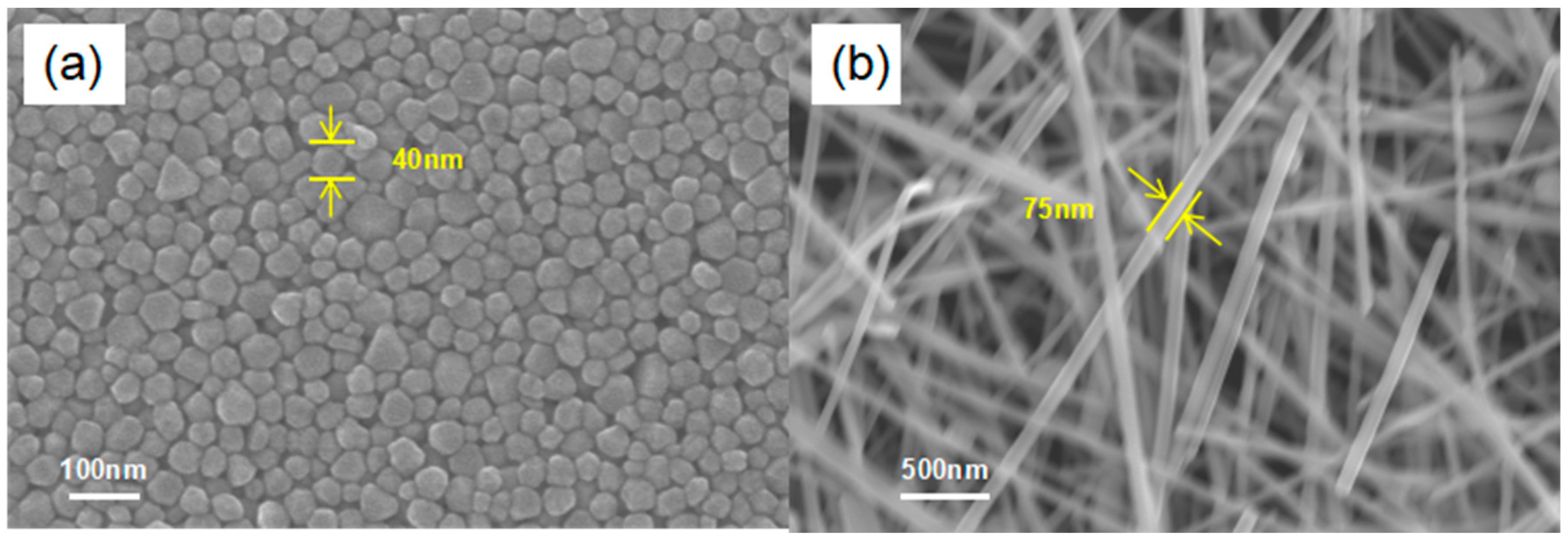
| AgNP(0D) | Average diameter: 40 nm, |
| CNT(1D) | Average diameter: 30 nm, Length: less than 2 μm |
| AgNW(1D) | Average diameter: 75 nm, Length: less than 5 μm |
| G(2D) | Average width: 10 μm |
| Sample | Filler (30 wt.%) | Solvent (69.9 wt.%) | Surfactant (0.1 wt.%) | |
|---|---|---|---|---|
| Pure Ag NP | Ag NP | H2O | EG | TX-100 |
| Ag NP/AC | 29.7%Ag NP, 0.3%AC | H2O | EG | TX-100 |
| Ag NP/Ag NW | 24%Ag NP, 6%Ag NW | H2O | EG | TX-100 |
| Ag NP/CNT | 29.7%Ag NP, 0.3%CNT | H2O | EG | TX-100 |
| Ag NP/G | 29.7%Ag NP, 0.3%G | H2O | EG | TX-100 |
© 2018 by the authors. Licensee MDPI, Basel, Switzerland. This article is an open access article distributed under the terms and conditions of the Creative Commons Attribution (CC BY) license (http://creativecommons.org/licenses/by/4.0/).
Share and Cite
Wang, X.; Guo, W.; Zhu, Y.; Liang, X.; Wang, F.; Peng, P. Electrical and Mechanical Properties of Ink Printed Composite Electrodes on Plastic Substrates. Appl. Sci. 2018, 8, 2101. https://doi.org/10.3390/app8112101
Wang X, Guo W, Zhu Y, Liang X, Wang F, Peng P. Electrical and Mechanical Properties of Ink Printed Composite Electrodes on Plastic Substrates. Applied Sciences. 2018; 8(11):2101. https://doi.org/10.3390/app8112101
Chicago/Turabian StyleWang, Xinda, Wei Guo, Ying Zhu, Xiaokang Liang, Fude Wang, and Peng Peng. 2018. "Electrical and Mechanical Properties of Ink Printed Composite Electrodes on Plastic Substrates" Applied Sciences 8, no. 11: 2101. https://doi.org/10.3390/app8112101
APA StyleWang, X., Guo, W., Zhu, Y., Liang, X., Wang, F., & Peng, P. (2018). Electrical and Mechanical Properties of Ink Printed Composite Electrodes on Plastic Substrates. Applied Sciences, 8(11), 2101. https://doi.org/10.3390/app8112101