Article

Multiaxial Fatigue Assessment of Railway Bogie Welded Joints: A Preliminary Study Based on Critical Plane Criterion


Department of Industrial Engineering, University of Florence, Via Santa Marta, 3, 50139 Florence, Italy
*
Author to whom correspondence should be addressed.
Appl. Sci. 2026, 16(8), 3935; https://doi.org/10.3390/app16083935
Submission received: 28 March 2026 / Revised: 14 April 2026 / Accepted: 16 April 2026 / Published: 18 April 2026

Abstract

The structural integrity of bogie frames is a critical factor in the safety and reliability of railway rolling stock, requiring advanced assessment methods to handle complex, multi-axial stress states. This research presents a robust numerical framework for the preliminary fatigue evaluation of a metro bogie frame, integrating high-fidelity Finite Element Analysis (FEA) with the Findley multi-axial fatigue criterion. The methodology overcomes the limitations of traditional uniaxial verification methods by employing a localized critical plane approach, implemented through a proprietary computational code. The investigation simulates a realistic operational scenario by superimposing a static vertical load of 15 tons per side with dynamic components derived from on-track accelerometric data. This integrated loading condition enables a precise reproduction of the “rotating” stress states typically encountered in service. Global structural analysis identified critical transverse welded joints as high-stress concentration zones, which were then subjected to a detailed multi-axial investigation. By correlating the extracted stress tensors with the resistance category included in the reference standard, over a regulatory life of 10 million cycles, a maximum cumulative damage index of 0.4602 was recorded. The results demonstrate that while the frame possesses adequate structural reserves, nearly half of its fatigue life is consumed in localized nodes. This methodology provides a reliable and computationally efficient tool for the structural health monitoring and development of innovative railway geometries, offering a superior predictive capability that remains scarcely utilized by major rolling stock manufacturers.

1. Introduction

In the current landscape of railway engineering, the synthesis of structural lightness and high mechanical reliability represents a primary challenge. Reducing the tare mass of rolling stock is directly linked to decreased energy consumption and minimized track wear, but it must be balanced against the strictly defined limits of fatigue life. In the automotive industry, structural optimization is routinely employed to achieve this balance, ensuring that mass reduction does not compromise the fatigue strength and crashworthiness of chassis components [1,2,3,4,5,6]. These methodologies often integrate manufacturing constraints to prevent localized fatigue hotspots caused by suboptimal geometries [7,8,9,10]. Similarly, in the field of additive manufacturing (AM) for turbomachinery, the synergy between optimization and AM has allowed for optimized load paths that specifically target the enhancement of structural response and fatigue durability under high-frequency operating cycles [11,12,13,14,15,16,17]. Within the railway sector, however, the application of such advanced fatigue-driven design remains comparatively limited. Railway bogies must satisfy coupled requirements of static strength and high-cycle fatigue resistance under highly stochastic loading scenarios. Despite some research on bogie redesign using micro-genetic algorithms [18] and topology optimization [19,20,21], the primary obstacle remains the conservative nature of European design standards, which rely on traditional verification protocols rather than optimization-based fatigue assessment. This is particularly critical when exploring new materials, such as composite systems [22], where fatigue behavior differs significantly from traditional steel. The necessity of accurately predicting the fatigue life of the bogie frame has led to the development of coupled dynamic analysis to capture realistic operational loads [23,24,25,26]. These durability-oriented approaches are essential for identifying potential failure points in welded structures. Extensive experimental fatigue campaigns on metro bogie frames [27,28] have further highlighted the impact of high-frequency track-induced vibrations on crack initiation. While optimization techniques are increasingly applied to car bodies to maintain fatigue resistance while reducing weight [29,30,31,32,33], the emergence of digital twin technologies represents a transformative shift in monitoring these fatigue-critical components [34,35,36,37,38,39]. By leveraging real-time accelerometric inputs, the digital twin allows for a continuous assessment of the damage accumulation during service. Despite these advancements, a significant gap remains in the implementation of localized, multi-axial fatigue criteria within these innovative workflows. Most current industrial practices still rely on simplified uniaxial stress assessments, which often fail to accurately characterize the damage in the complex, multi-axially stressed welded regions of a bogie frame. The present research addresses this limitation by proposing a validation-focused methodology that integrates high-fidelity FE modeling with a localized Findley-based critical plane analysis. By bridging the gap between standardized regulatory requirements and advanced multi-axial fatigue theory, this study introduces a high-precision framework that serves as an essential precursor to the reliable, fatigue-safe optimization of next-generation railway structures.

2. Materials and Methodology

The present section details the comprehensive methodological framework developed to assess the fatigue life of a metro bogie frame in a preliminary study. The research strategy is designed to integrate standardized industrial practices with advanced numerical criteria, ensuring a robust evaluation of welded joints under complex operational conditions. The approach is systematically structured to cover every phase of the structural assessment, beginning with a detailed definition of the mechanical role and architectural features of the metro bogie frame. This is followed by the description of the high-fidelity Finite Element (FE) model properties, which serve as the numerical foundation for all subsequent simulations. To overcome the inherent limitations of conventional stress-based assessments, the Findley Fatigue Criterion is implemented as the primary multi-axial evaluation tool, allowing for a more precise determination of the critical stress states. The workflow concludes with the damage accumulation procedure, which translates the identified critical plane parameters into a reliable life-cycle prediction. This final stage is performed in full compliance with current European regulatory standards, ensuring that the innovation of the multi-axial approach remains anchored to established safety requirements.

2.1. Methodology

The present research activity is focused on enhancing the structural assessment of one of the most mechanically critical components in rolling stock: the bogie frame. The primary objective is to implement an advanced fatigue evaluation framework that ensures rigorous compliance with the European standards governing railway structural integrity. This methodological approach integrates high-fidelity numerical modeling with localized multi-axial fatigue criteria, specifically designed to overcome the limitations of traditional uniaxial verification methods, calculated with a proprietary code. The proposed workflow is structured into several key stages, described in detail below, which collectively enable the identification of critical regions and a reliable prediction of the component’s performance under complex loading conditions:
  • A detailed FE model of the bogie frame was constructed, incorporating all auxiliary equipment supports and primary load interfaces. This ensures a precise reproduction of the mechanical interactions and boundary conditions existing between the frame and its interconnected subsystems.
  • A comprehensive mechanical verification was conducted to meet the static and fatigue requirements defined by European railway standards. In this preliminary phase, the computational framework was validated by simulating a realistic operational scenario through the superposition of a static load and a dynamic component derived from accelerometric data. This integrated loading condition was specifically designed to replicate actual service environments, ensuring that the subsequent numerical results and the robustness of the procedure were evaluated under quasi-real operating stresses.
  • Based on the preliminary findings from the regulatory assessment, specific welded joints were identified as high-stress concentration zones. These regions, deemed critical for the structural durability of the component, were selected as the primary subjects for the subsequent localized fatigue investigation.
  • For the nodes and elements belonging to the identified critical sets, the full stress tensors were extracted. These data were processed using the Findley criterion to determine the critical plane orientation, exploiting an external proprietary code. This multi-axial approach allows for the isolation of the shear stress amplitude and maximum normal stress components acting on the orientation most susceptible to fatigue failure.
  • The final fatigue damage was quantified using the Palmgren-Miner linear accumulation rule. The damage calculation integrates the stress components derived from the critical plane analysis with the S-N fatigue resistance curves provided by Eurocode 3 (EN 1993-1-9) [40], ensuring the assessment aligns with established structural engineering practices.
The present research methodology aims to address the limitations of conventional fatigue assessments, which often prove insufficient for accurately predicting the durability of highly complex components like bogie frames. The proposed approach establishes a rigorous framework that integrates multi-axial fatigue theory with current European regulatory requirements, maintaining a streamlined and computationally efficient workflow. By combining high-fidelity finite element modeling with a localized Findley-based critical plane analysis, this procedure enables a more precise identification of fatigue-prone regions than standard uniaxial methods. Consequently, this preliminary methodology provides a reliable and practical tool for the preliminary assessment of welded structures, ensuring that the development of innovative bogie geometries is grounded in robust mechanical verification and standardized safety protocols.

2.2. Model Description: The Metro Bogie Frame

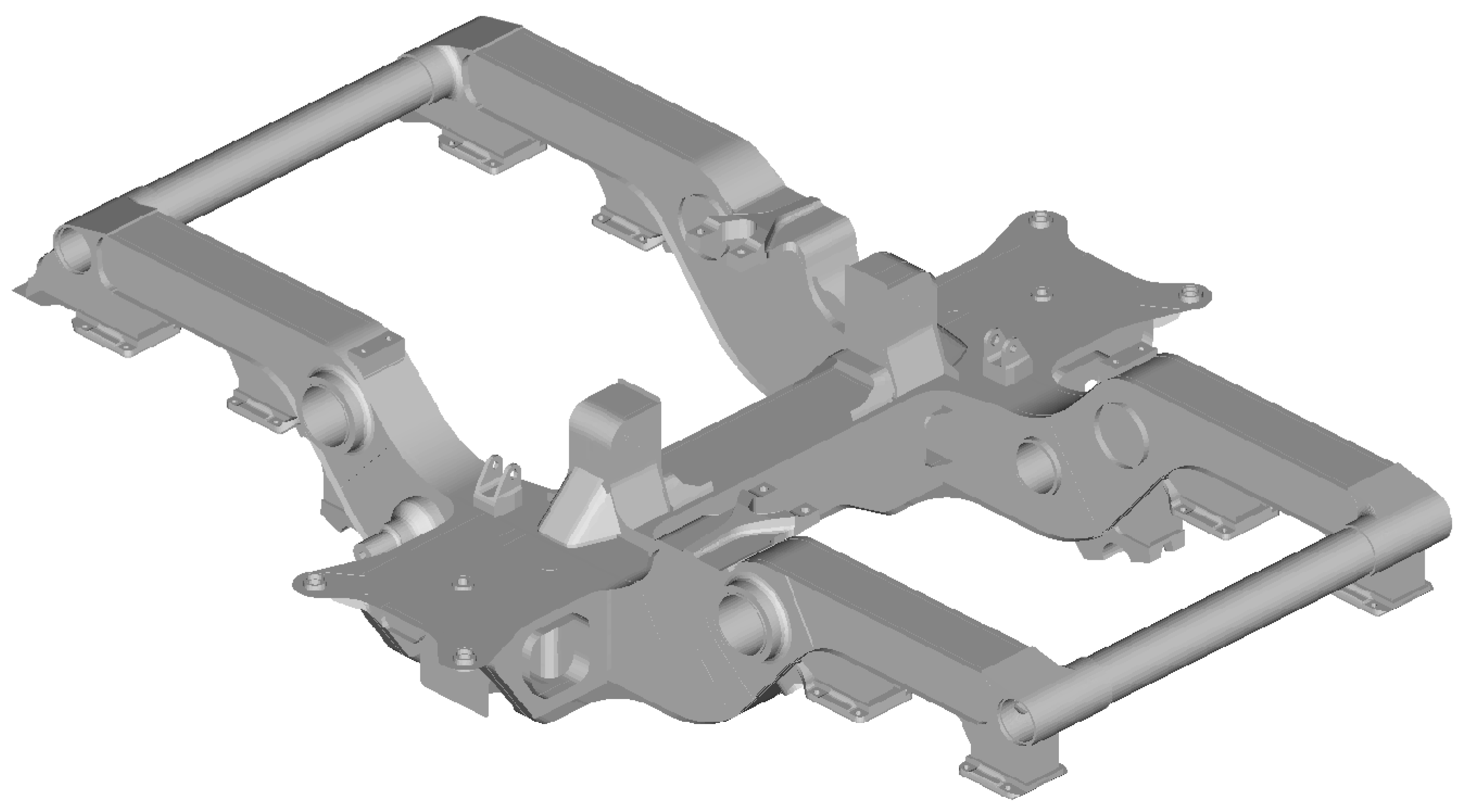
Although the vehicle assembly is not the primary focus of this investigation, a comprehensive structural evaluation would necessitate compliance with EN 12663-1 [41] and EN 15663 [42] standards. The component under analysis is specifically engineered to ensure the structural integrity, durability, and resilience required by the demanding operational profiles of modern transit systems. As a core structural element, the frame integrates multiple subsystems within the rolling stock underbody. To withstand the rigorous conditions of metro service, the architecture is designed to sustain intense dynamic loads arising from track irregularities while maintaining high reliability. The manufacturing process involves advanced precision and automated welding techniques, ensuring high levels of uniformity and structural continuity across the steel assemblies. Despite these high-quality standards, welded joints represent the most critical regions in railway bogie frames, particularly when considering fatigue life under cyclic loading conditions. Architecturally, the frame consists of a strategic arrangement of longitudinal beams and cross-members, optimized to distribute operational loads effectively across the entire structure. This geometric configuration is pivotal not only for the bogie’s lateral stability but also for the overall safety and performance of the vehicle. Specifically, the end crossbeams are dimensioned to provide the necessary torsional stiffness. Furthermore, a key feature is the hollow section positioned beneath the secondary suspension housing; this void is intentionally designed to accommodate the traction link, enabling its connection to the bolster beam at the distal end. The bogie frame, depicted in Figure 1, was fabricated from structural steel [43] and finalized through a complete welding assembly.

2.3. Model Description: FE Model Properties

The numerical representation of the initial bogie frame was developed using a high-fidelity FE approach within the Altair environment [44]. The global assembly is presented in Figure 2. The primary architecture, comprising the longitudinal beam, the central crossbeam, and the perimeter crossbeams, was discretized using a two-dimensional mesh. Specifically, QUAD4 shell elements were employed, featuring a nominal average size of 10 mm and a localized refinement down to 3 mm. This discretization strategy was validated through a preliminary mesh sensitivity analysis, which ensured that the grid density was sufficient to provide converged and reliable stress distributions. In contrast to the main frame, the various supports described in the previous section were modeled using a three-dimensional mesh consisting of second-order TETRA10 elements. Although these solid elements share the same characteristic dimensions as the 2D mesh, their selection was dictated by the complex volumetric geometry of the supports, which would not be accurately captured by a shell formulation. A significant modeling challenge arose from the direct connection of the 1st-order 2D elements to the 3D solid mesh. To overcome the kinematic incompatibility between these different formulations, a freeze/bonded contact condition was implemented. This configuration is crucial for maintaining the linearity of the model while ensuring a seamless redistribution of both forces and moments across the interfaces. Specifically, this constraint enforces a condition of zero relative motion: the initial gap between the contacting surfaces remains constant, and any sliding distance is strictly suppressed. This approach not only enhances the accuracy and robustness of the results but also significantly simplifies the modeling process. Furthermore, this modular strategy allows for the independent modification of individual subsystems (supports or frame), drastically reducing the time required for design iterations and subsequent numerical simulations. The application of loads followed a differentiated strategy based on the specific target zone. To avoid the introduction of artificial parasitic stiffness, zero-dimensional RBE3 elements were utilized alongside conventional force and pressure boundary conditions. These elements facilitate an effective load distribution among the nodes without distorting the local structural response. The primary suspension system acts as the elastic stage between the bogie frame and the wheelset. This component was modeled using one-dimensional elements to avoid excessively rigid constraints that could lead to non-physical stress concentrations. Similarly, the axle and the pin seat were represented via 1D beam elements with congruent cross-sections. The conical rubber-metal suspension was further refined by employing a pair of 1D spring elements, which were coupled to the supports through RBE3 multi-node rigid elements. Finally, the boundary conditions for all analyzed load cases were defined using an isostatic configuration, referencing the four-wheel positions at the axle extremities. The completed FE model consists of approximately 500,000 elements and 680,000 nodes.

2.4. Findley Fatigue Criterion

In order to accurately assess the fatigue life of the welded joints under complex, multi-axial loading, the Findley criterion was implemented. Unlike traditional stress-based methods, this critical plane approach accounts for the interaction between shear and normal stress components on a specific physical plane. The Findley parameter (FP) is defined by the following expression (Equation (1)):
F P = max θ , ϕ τ a + k σ n , m a x
where τ a represents the shear stress amplitude and σ n , m a x is the maximum normal stress acting on the plane during a loading cycle. The coefficient k is a material-dependent sensitivity factor that accounts for the influence of the normal stress on the fatigue limit.
A sensitivity fatigue coefficient k = 0.3 was adopted, consistent with literature data for structural steel components under multi-axial cyclic loading [45]. The criterion identifies the critical plane as the orientation θ , ϕ that maximizes the FP value. This approach is particularly effective for ductile materials and welded assemblies in railway applications, as it successfully captures the physical mechanisms of crack initiation driven by cyclic shear and accelerated by tensile normal stresses.

2.5. Damage Accumulation and Regulatory Compliance

The transition from the multi-axial stress state to the cumulative damage estimation is performed by correlating the Findley parameter with the fatigue resistance curves defined in Eurocode 3, previously cited in [40]. Once the critical plane is identified, an equivalent stress range, Δ σ e q , is derived from the calculated fatigue parameter. This equivalent range is then compared against the S-N curves (Wöhler curves) corresponding to the specific detail categories of the bogie’s welded joints. For each stress cycle identified in the load history, the permissible number of cycles to failure, N i is determined according to the slope and endurance limit of the regulatory curve. The total fatigue life consumption is finally quantified through the Palmgren-Miner linear damage accumulation rule (Equation (2)):
D = i = 1 n n i N i
where n i represents the actual number of cycles at a given stress level. According to this framework, structural failure is conventionally predicted when the cumulative damage index D reaches the unity threshold (D = 1). This integrated approach allows for a standardized verification that combines the physical accuracy of the critical plane method with the safety margins and reliability required by European railway legislation.

3. Results and Discussions

The results obtained from the numerical simulations and the subsequent fatigue assessment are presented and discussed in this section. The analysis follows the multi-stage workflow defined in the methodology, starting from the global structural response and progressing toward the localized damage evaluation of the identified critical regions. By integrating the results of the static load case with the dynamic cycles processed via the Rainflow method, a comprehensive overview of the bogie frame’s performance under realistic operating conditions is provided. The discussion focuses on the effectiveness of the Findley criterion in capturing multi-axial stress states and its implications for the fatigue life prediction of welded assemblies, ultimately validating the robustness of the proposed preliminary assessment framework.

3.1. Load Scenario

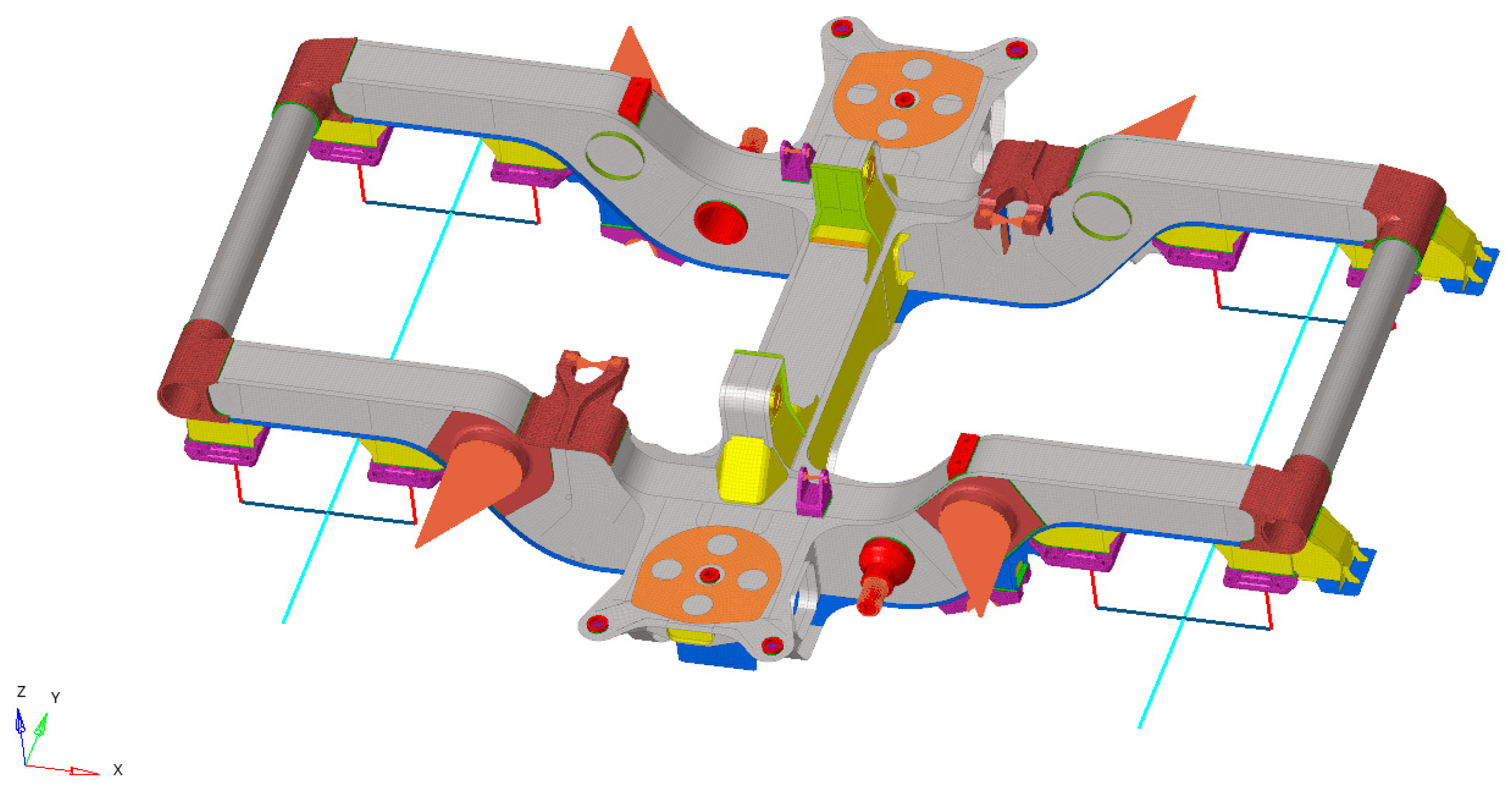
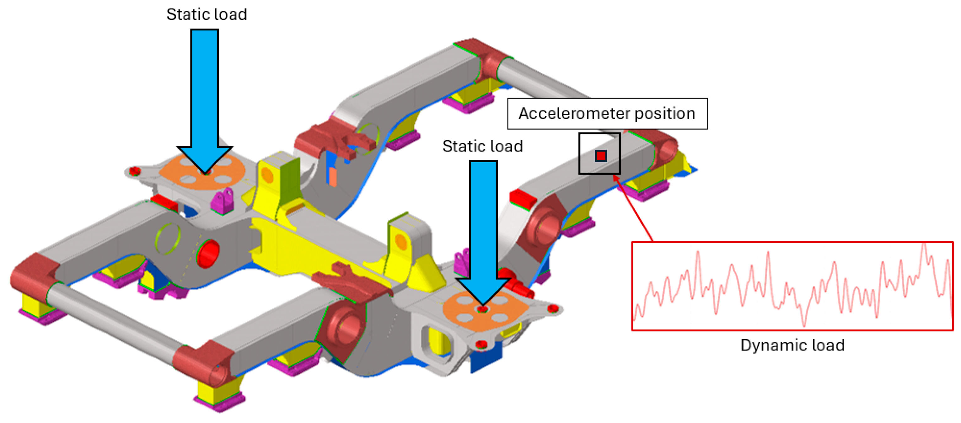
The structural evaluation of the metro bogie frame was performed by applying the loading scenarios defined in EN 13749:2021 [45]. To ensure a high-fidelity representation of the actual service conditions, the model incorporates a hybrid loading strategy, as illustrated in Figure 3. The vertical loads, representing the static weight of the vehicle body and passengers, were applied directly to the secondary suspension seats. Concurrently, to account for the inertial effects and track-induced vibrations, a dynamic load component was integrated. This dynamic input was derived from accelerometric time-series data captured at a strategic position on the extremal section of the longitudinal beam (side frame). By superimposing this high-frequency accelerometric signal onto the quasi-static load case, the study replicates the complex stress state typical of real-world metro operations. This approach allows for a more rigorous assessment of the frame’s response to both sustained operational weights and transient dynamic excitations, providing a robust dataset for the subsequent fatigue analysis.
Following the configuration illustrated in the previous figure, the static load was applied to the secondary suspension seats of the bogie frame. This load case represents approximately one-quarter of the total vehicle mass, including the passenger payload. To ensure a conservative structural assessment, a cautious approach was adopted, assuming a static vertical load of 15 tons per side. This value provides a safety margin for the preliminary evaluation of the frame’s structural integrity under maximum service weight. The dynamic contribution was obtained from accelerometric time-series data recorded during operational tests, showing peak vertical accelerations of up to 20 g. To account for these high-intensity fluctuations within the fatigue study, the signal was processed using the Rainflow-counting algorithm, which discretized the complex history into individual load cycles. Given the linear-elastic nature of the FE model, the principle of superposition of effects was exploited to process these cycles. Specifically, each load cycle was applied independently, and the resulting stress components were subsequently aggregated to determine the total transient stress state. This modular approach not only ensures computational efficiency but also provides a robust representation of the extreme stress environment the bogie frame encounters during service.

3.2. FE Model Assessment and Global Stress State

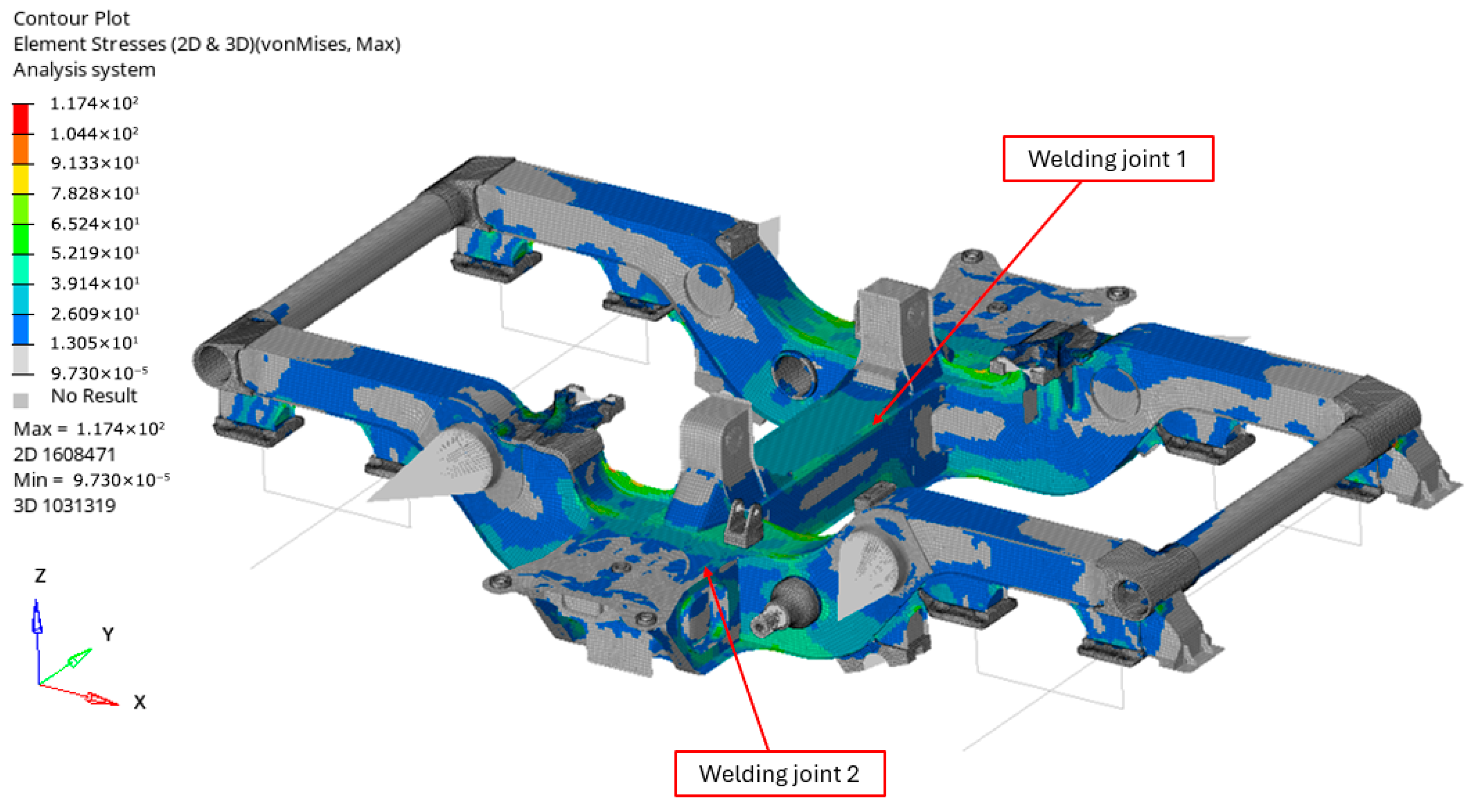
The preliminary phase of the investigation involved a global structural assessment of the bogie frame to evaluate the stress distribution under the defined operational loads. As illustrated in Figure 4, the primary mechanical response is concentrated within the central region of the assembly, specifically involving the main crossbeam and the secondary suspension housings. For the initial application of the critical plane methodology, two representative transverse welding joints were selected for localized analysis. These joints, explicitly labeled in Figure 4, exhibited significant static stress levels, making them ideal candidates for verifying the fatigue framework. Under the current loading conditions, the maximum stresses recorded for the S275 structural steel remain well within the elastic regime. The material model was linear and the reference properties adopted for the simulations included a Young’s Modulus of 210,000 MPa, a Poisson’s ratio of 0.3, and a density of 7850 kg/m3. In order to quantify this margin, a utilization coefficient, defined as the ratio between the calculated von Mises stress and the material’s yield strength, was evaluated. In all monitored regions, this coefficient was found to be significantly below unity, confirming the absence of localized plastic deformation and the overall structural integrity of the frame. It is essential to emphasize that the focus of this research is the application of the critical plane method to a highly complex railway case study. Consequently, the global stress state serves as a validated baseline for the subsequent implementation of the fatigue-prediction algorithm, prioritizing the robustness of the methodological workflow over specific geometric optimization.
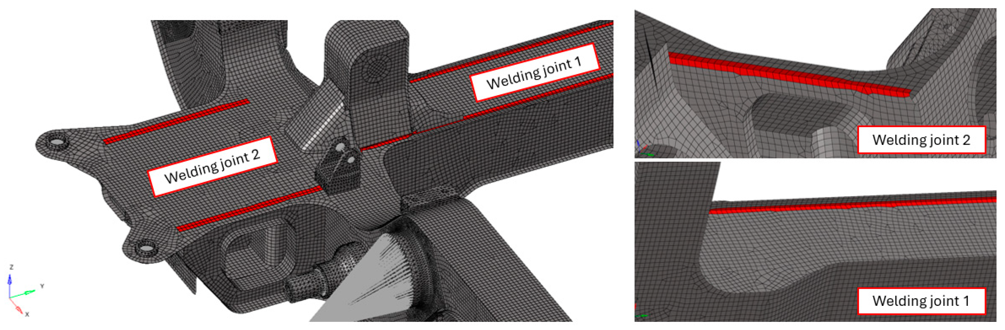
The bogie frame assembly and all the welded joints are modeled using a node-equivalence approach at the interfaces, a consolidated technique in the railway sector for global structural assessments. As illustrated in Figure 5, the focus is placed on the transverse welding joints selected, which represent the most critical locations for fatigue crack initiation due to high-stress concentrations.

3.3. Multi-Axial Fatigue Assessment (Findley Results)

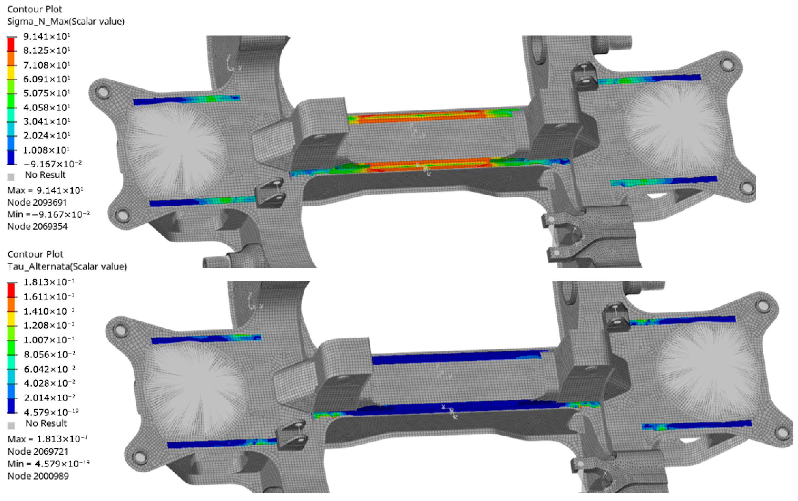
Following the identification of the critical welded regions, the multi-axial fatigue life was evaluated by extracting the local stress tensors and applying the Findley criterion. This stage represents the core of the numerical investigation, where the interaction between different stress components on the critical plane is quantified. The results of the critical plane search are illustrated in Figure 6, which displays the contour plots for the maximum normal stress ( σ n , m a x ) and the alternating shear stress ( τ a ) relative to the most damaging orientation. A comparative analysis of the two stress components reveals that the normal stress ( σ m a x ) is clearly the preponderant factor acting on the critical plane for the investigated bogie joints. Specifically, while the shear components ( τ a ) remain relatively low across the welded beads, the normal stress reaches significantly higher magnitudes. This indicates that the fatigue mechanism in these specific transverse welds is primarily driven by opening (Mode I) tensile cycles rather than pure sliding (Mode II or III) shear cycles.
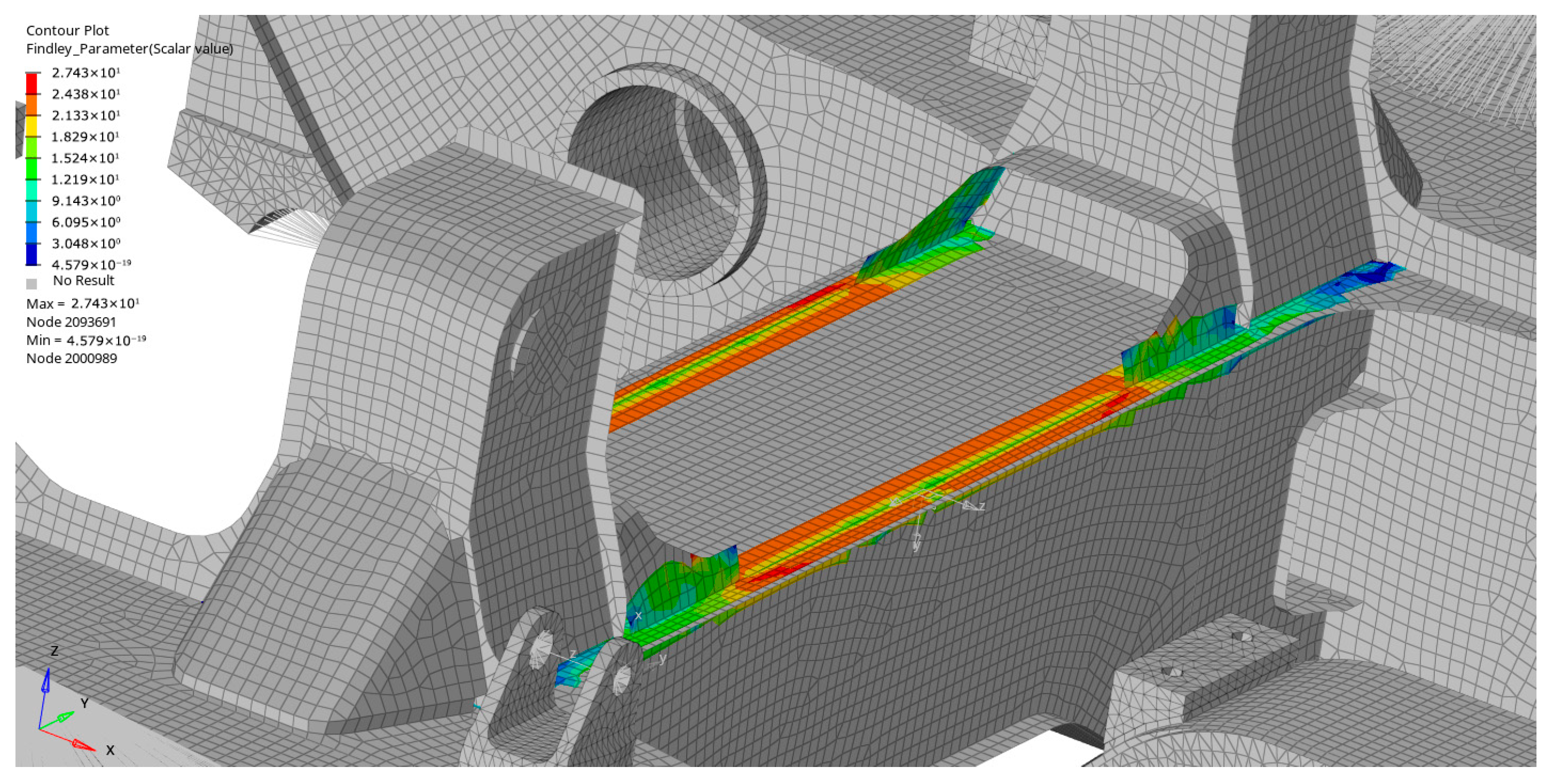
The final distribution of FP is presented in Figure 7. The spatial mapping of FP confirms that the fatigue risk is non-uniformly distributed along the welding line, with peak values concentrated at the interface between the sideframe and the central cross-beam. The FP distribution is markedly dominated by the tensile contribution, whose role is primary in crack initiation by reducing the threshold for shear-induced damage. From a structural perspective, these results highlight the sensitivity of the transverse joints to the vertical bending and torsional loads of the bogie frame. The high values of FP recorded in these areas, despite the global stresses being below the yield limit, justify the need for a multi-axial approach. Standard uniaxial assessments might underestimate the damaging effect of the high mean normal stresses that the Findley criterion, conversely, correctly incorporates into the fatigue parameter. This detailed, localized mapping provides the necessary input for the final damage accumulation phase, ensuring that the most vulnerable nodes are accurately monitored.

3.4. Cumulative Damage and Comparative Discussion

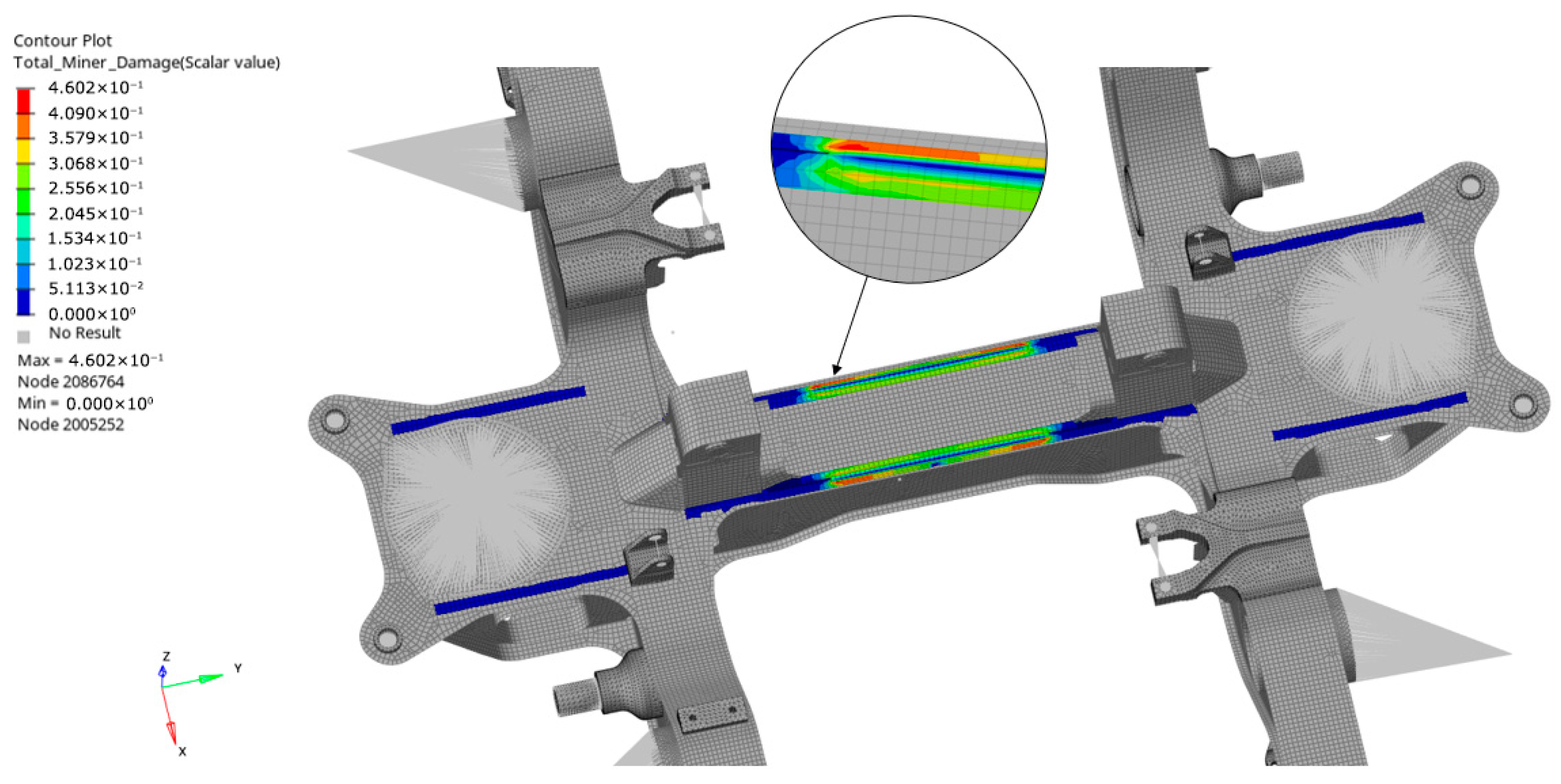
The culmination of the numerical investigation involves the translation of the multi-axial fatigue parameters into a quantifiable measure of structural life consumption. For this purpose, the equivalent stress ranges derived from the Findley-based critical plane analysis were correlated with the FAT 100 detail category as defined in EN 1993-1-9 (Eurocode 3) [40]. In accordance with railway technical specifications for structural durability, the damage assessment was conducted by projecting the recorded stress states over a reference life of 10 million cycles. This cycle count serves as a standard regulatory benchmark to ensure the long-term reliability of the bogie frame under sustained operational vibrations. By applying the Palmgren-Miner linear accumulation rule over this extended loading history, reconstructed from the high-frequency accelerometric data, the nodal damage distribution was successfully mapped across the critical welded interfaces. As illustrated in the contour plot of Figure 8, the maximum accumulated damage index Dmax reaches a peak value of 0.4602 (Node 2086764). This result is particularly revealing: it indicates that under the action of 10 million operational cycles, the most stressed welding joint consumes approximately 46% of its theoretical fatigue life. Although this value remains comfortably below the critical threshold of unity (D < 1), its magnitude is significant given the high fatigue resistance class (FAT 100) employed. This confirms that the localized stress concentration at the weld toe, induced by the stresses shown in Figure 6, remains a dominant factor in the assembly’s durability. The damage gradient shown in the magnified section of Figure 8 underscores how the fatigue consumption is strictly confined to the geometric discontinuity of the joint, where the interaction between the 15-ton static load and the transient accelerometric excitations is most severe.
The strategic advantage of employing the Findley criterion over more traditional methods, such as the Maximum Principal Stress approach, becomes evident when analyzing these localized results. Conventional uniaxial methods typically identify the maximum damage by considering only the highest normal stress component, often ignoring the phase shift and the combined effect of shear components. In contrast, the Findley criterion identifies the critical plane based on a physical interaction between shear stress amplitude and maximum normal stress (Equation (1)). While a principal stress analysis might accurately locate the region of highest tension, it fails to account for how cyclic shear promotes crack initiation on specific orientations, especially in non-proportional loading scenarios where the principal stress axes rotate during the cycle. By using Findley’s method, the rotating stress state is handled by searching for the physical plane that maximizes the fatigue parameter, providing a much more nuanced and reliable map of the actual risk. This superior level of detail allows for a more targeted structural health monitoring strategy, ensuring that inspection efforts are focused on the nodes where the multi-axial stress interaction, rather than just the peak magnitude, is most likely to trigger fatigue failure. Finally, the computational efficiency of the proposed workflow represents a key factor for its applicability in the industrial sector. The fatigue assessment, based on the FAT 100 resistance category, demonstrated excellent computational performance despite the inherent complexity of the Findley multi-axial criterion. The mathematical workload, which is required to scan the critical planes and process the full stress history, was handled with high efficiency by the proprietary code. Through optimized data management and advanced vectorization techniques, the complete evaluation of a critical welded detail was processed in approximately 12 min. This processing time is remarkably well-balanced, with the computational effort equally distributed between the FE solver and the fatigue analysis script. Such a reactive and efficient workflow confirms that the proposed methodology, while maintaining a rigorous mechanical approach, is fully compatible with the rapid design and validation cycles required by modern rolling stock manufacturers.

3.5. Final Methodological Comparison and Discussion

The implementation of the Findley critical plane criterion represents a specialized advancement over traditional stress-invariant or uniaxial methods, such as the Maximum Principal Stress (MPS) or the von Mises equivalent stress, which remain the baseline for standardized structural assessment. While MPS-based approaches are highly effective and widely validated for proportional loading scenarios in railway engineering, their application can be more challenging under the complex, non-proportional dynamic duty cycles identified in this study. With peak accelerations reaching 20 g or more, the principal stress axes undergo significant rotation due to the nature of the load, a condition where the physical orientation of the damage becomes a critical factor. Recent literature reviews [46,47] emphasize that for welded joints subjected to such multiaxial loading, the fatigue life is better characterized by the interaction between the maximum shear stress and the acting normal stress on the critical plane. Traditional uniaxial methods, while consolidated and reliable for general design, do not explicitly account for the phase-shift between these stress components, a phenomenon that has been documented as a key variable in high-fidelity fatigue estimation [48]. By adopting a localized critical plane framework, this study aligns with advanced predictive methodologies emerging in other high-performance sectors [49], complementing existing standards with a deeper insight into the physical mechanisms of fatigue crack initiation. Consequently, this approach provides a refined indicator of structural integrity that accounts for the specific transient dynamics of high-intensity operational cycles. Although the primary European standards do not yet formally incorporate this methodology into ordinary verification protocols, it undoubtedly holds significant potential for future applications in the optimization and validation of next-generation railway structures, offering a valuable tool to supplement current analytical practices.

4. Conclusions

The present research successfully validated an advanced numerical framework for the fatigue assessment of a metro bogie frame, integrating high-fidelity Finite Element Analysis with a localized implementation of the Findley multi-axial criterion. By integrating a static load of 15 tons per side with dynamic accelerometric data, the study replicated a quasi-real operational environment that allowed for a rigorous evaluation of the component’s structural integrity. The preliminary global stress analysis correctly identified the critical transverse welded joints between the sideframe and the cross-beam, where the localized stress concentrations, primarily driven by normal tensile components on the critical plane, were found to be the dominant factor in fatigue life consumption. By projecting these stress states over a regulatory benchmark of 10 million cycles and adopting a FAT 100 resistance category in accordance with EN 1993-1-9 (Eurocode 3), a maximum cumulative damage index of 0.4602 was recorded. This quantitative result not only confirms that the bogie frame possesses adequate structural reserves for the simulated service conditions but also demonstrates that nearly half of its theoretical fatigue life is consumed in specific localized nodes. The strategic advantage of this methodology lies in its ability to overcome the limitations of traditional uniaxial principal stress methods, which often struggle to account for the “rotating” stress states induced by non-proportional loading. Through the search for the physical critical plane using a proprietary code, the proposed workflow provides a more precise and reliable map of fatigue risk, offering a standardized and computationally efficient tool for the preliminary assessment of complex welded structures and the development of innovative, durable railway geometries. This high-precision methodology opens the way to a new design approach that, despite its superior predictive capabilities, remains scarcely utilized by major rolling stock manufacturers.

Author Contributions

Conceptualization, methodology, software, simulation, validation, review A.C. and S.B.; review, supervision, project administration, A.C., E.M. and A.R. All authors have read and agreed to the published version of the manuscript.

Funding

This research received no external funding.

Data Availability Statement

The original contributions presented in the study are included in the article, further inquiries can be directed to the corresponding author.

Conflicts of Interest

The authors declare no conflicts of interest.

References

  1. Kong, Y.S.; Abdullah, S.; Omar, M.Z.; Haris, S.M. Topological and Topographical Optimization of Automotive Spring Lower Seat. Lat. Am. J. Solids Struct. 2016, 13, 1388–1405. [Google Scholar] [CrossRef]
  2. Jankovics, D.; Barari, A. Customization of Automotive Structural Components using Additive Manufacturing and Topology Optimization. IFAC-PapersOnLine 2019, 52, 212–217. [Google Scholar] [CrossRef]
  3. Su, H.; An, D.; Ma, L.; He, Y. A survey of multi-scale optimization methods in fiber-reinforced polymer composites design for automobile applications. Proc. Inst. Mech. Eng. Part D J. Automob. Eng. 2025, 240, 805–821. [Google Scholar] [CrossRef]
  4. Billur, S.; Raju, G.U. Mass Optimization of Automotive Radial Arm Using FEA for Modal and Static structural Analysis. IOP Conf. Ser. Mater. Sci. Eng. 2021, 1116, 012113. [Google Scholar] [CrossRef]
  5. Viqaruddin, M.; Reddy, D.R. Structural optimization of control arm for weight reduction and improved performance. Mater. Today Proc. 2017, 4, 9230–9236. [Google Scholar] [CrossRef]
  6. Matsimbi, M.; Nziu, P.K.; Masu, L.M.; Maringa, M. Topology optimization of automotive body structures: A review. Int. J. Eng. Res. Technol. 2021, 13, 4282–4296. [Google Scholar]
  7. Yan, L.; Guo, Q.; Yang, S.; Liao, X.; Qi, C. A size optimization procedure for irregularly spaced spot weld design of automotive structures. Thin-Walled Struct. 2021, 166, 108015. [Google Scholar] [CrossRef]
  8. Yang, S.; Yan, L.; Qi, C. An adaptive multi-step varying-domain topology optimization method for spot weld design of automotive structures. Struct. Multidiscip. Optim. 2018, 59, 291–310. [Google Scholar] [CrossRef]
  9. Liu, Y.; Liu, Z.; Qin, H.; Zhong, H.; Lv, C. An efficient structural optimization approach for the modular automotive body conceptual design. Struct. Multidiscip. Optim. 2018, 58, 1275–1289. [Google Scholar] [CrossRef]
  10. Fonseca, J.; Lee, J.; Jang, W.; Han, D.; Kim, N.; Lee, H. Manufacturability-constrained optimization for enhancing quality and suitability of injection-molded short fiber-reinforced plastic/metal hybrid automotive structures. Struct. Multidiscip. Optim. 2023, 66, 113. [Google Scholar] [CrossRef]
  11. Zhu, J.; Zhou, H.; Wang, C.; Zhou, L.; Yuan, S.; Zhang, W. A review of topology optimization for additive manufacturing: Status and challenges. Chin. J. Aeronaut. 2020, 34, 91–110. [Google Scholar] [CrossRef]
  12. Zegard, T.; Paulino, G. Bridging topology optimization and additive manufacturing. Struct. Multidiscip. Optim. 2016, 53, 175–192. [Google Scholar] [CrossRef]
  13. Wang, W.; Munro, D.; Wang, C.; Van Keulen, F.; Wu, J. Space-time topology optimization for additive manufacturing. Struct. Multidiscip. Optim. 2019, 61, 1–18. [Google Scholar] [CrossRef]
  14. Sabiston, G.; Kim, I. 3D topology optimization for cost and time minimization in additive manufacturing. Struct. Multidiscip. Optim. 2020, 61, 731–748. [Google Scholar] [CrossRef]
  15. Cascino, A.; Meli, E.; Rindi, A.; Pucci, E.; Matoni, E. Experimental Validation and Dynamic Analysis of Additive Manufacturing Burner for Gas Turbine Applications. Machines 2025, 13, 1111. [Google Scholar] [CrossRef]
  16. Pietropaoli, M.; Ahlfeld, R.; Montomoli, F.; Ciani, A.; D’Ercole, M. Design for Additive Manufacturing: Internal Channel Optimization. In Proceedings of the ASME Turbo Expo 2016: Turbomachinery Technical Conference and Exposition, Seoul, Republic of Korea, 13–17 June 2016. Volume 5B: Heat Transfer. [Google Scholar]
  17. Srivastava, P.K.; Shukla, S. Topology Optimization: Weight Reduction of Indian Railway Freight Bogie Side Frame. Int. J. Mech. Eng. 2021, 6, 4374–4383. [Google Scholar]
  18. Yamamoto, M. Non-parametric optimization of railway wheel web shape based on fatigue design criteria. Int. J. Fatigue 2020, 134, 105463. [Google Scholar] [CrossRef]
  19. Gersborg, A.R.; Andreasen, C.S. An explicit parameterization for casting constraints in gradient driven topology optimization. Struct. Multidiscip. Optim. 2011, 44, 875–881. [Google Scholar] [CrossRef]
  20. Cascino, A.; Meli, E.; Rindi, A. Development of a Methodology for Railway Bolster Beam Design Enhancement Using Topological Optimization and Manufacturing Constraints. Eng 2024, 5, 1485–1498. [Google Scholar] [CrossRef]
  21. Cascino, A.; Meli, E.; Rindi, A. Lightweight Design and Topology Optimization of a Railway Motor Support Under Manufacturing and Adaptive Stress Constraints. Vehicles 2026, 8, 3. [Google Scholar] [CrossRef]
  22. Lang, D.; Radford, D.W. Design Optimization of a Composite Rail Vehicle Anchor Bracket. Urban Rail Transit 2021, 7, 84–100. [Google Scholar] [CrossRef]
  23. Xiu, R.; Spiryagin, M.; Wu, Q.; Yang, S.; Liu, Y. Fatigue life prediction for locomotive bogie frames using virtual prototype technique. Proc. Inst. Mech. Eng. Part F J. Rail Rapid Transit 2021, 235, 1122–1131. [Google Scholar] [CrossRef]
  24. Guo, F.; Wu, S.C.; Liu, J.X.; Zhang, W.; Qin, Q.B.; Yao, Y. Fatigue life assessment of bogie frames in high-speed railway vehicles considering gear meshing. Int. J. Fatigue 2020, 132, 105353. [Google Scholar] [CrossRef]
  25. Cascino, A.; Giannelli, L.; Meli, E.; Rindi, A. Integration of fatigue life assessment into structural optimization of a railway vehicle bogie frame: Development and application of a new methodology. Railw. Eng. Sci. 2026. [Google Scholar] [CrossRef]
  26. Luo, R.K.; Gabbitas, B.L.; Brickle, B.V. Dynamic stress analysis of an open-shaped railway bogie frame. Eng. Fail. Anal. 1996, 3, 53–64. [Google Scholar] [CrossRef]
  27. Zhou, W.; Zhang, G.; Wang, H.; Peng, C.; Liu, X.; Xiao, H.; Liang, X. Experimental fatigue evaluation of bogie frames on metro trains. Machines 2022, 10, 1003. [Google Scholar] [CrossRef]
  28. Wang, W.; Bai, J.; Wu, S.; Zheng, J.; Zhou, P. Experimental investigations on the effects of fatigue crack in urban metro welded bogie frame. Appl. Sci. 2020, 10, 1537. [Google Scholar] [CrossRef]
  29. Genovese, A.; Russo, M.; Strano, S. Mechanical characterization and modeling of an innovative composite material for railway applications. Proc. Inst. Mech. Eng. Part L J. Mater. Des. Appl. 2017, 231, 122–130. [Google Scholar] [CrossRef]
  30. Cascino, A.; Distaso, F.; Meli, E.; Rindi, A. Multistage Static and Dynamic Optimization Framework for Composite Laminates in Lightweight Urban Rail Vehicle Car Bodies. Materials 2026, 19, 531. [Google Scholar] [CrossRef]
  31. Koenig, J. Integral consideration of the lightweight design for railway vehicles. In Young Researchers Seminar; Technical University of Denmark: Kongens Lyngby, Denmark, 2011. [Google Scholar]
  32. Cascino, A.; Meli, E.; Rindi, A. Optimal Design of CFRP Railway Carbody Laminates via Multi-Criterion Fiber Orientation Sensitivity. Materials 2026, 19, 1355. [Google Scholar] [CrossRef]
  33. Miao, B.R.; Luo, Y.X.; Peng, Q.M.; Qiu, Y.; Chen, H.; Yang, Z. Multidisciplinary design optimization of lightweight carbody for fatigue assessment. Mater. Des. 2020, 194, 108910. [Google Scholar] [CrossRef]
  34. Cascino, A.; Nencioni, L.; Lanzillo, L.; Mazzeo, F.; Strano, S.; Terzo, M.; Delle Monache, S.; Meli, E. Development and Experimental Validation of a Physics-Based Digital Twin for Railway Freight Wagon Monitoring. Sensors 2026, 26, 643. [Google Scholar] [CrossRef] [PubMed]
  35. Kushwaha, D.; Kumar, A.; Harsha, S. Advancements and applications of digital twin in the railway industry: A literature review. Int. J. Rail Transp. 2024, 13, 865–890. [Google Scholar] [CrossRef]
  36. Krmac, E.; Djordjević, B. Digital Twins for Railway Sector: Current State and Future Directions. IEEE Access 2024, 12, 108597–108615. [Google Scholar] [CrossRef]
  37. Adeagbo, M.; Wang, S.; Ni, Y. Revamping structural health monitoring of advanced rail transit systems: A paradigmatic shift from digital shadows to digital twins. Adv. Eng. Inform. 2024, 61, 102450. [Google Scholar] [CrossRef]
  38. Cascino, A.; Delle Monache, S.; Lanzillo, L.; Mazzeo, F.; Nencioni, L.; Nicolella, A.; Strano, S.; Terzo, M. Development and Experimental Testing of a 3D Vision System for Railway Freight Wagon Monitoring. Appl. Sci. 2025, 15, 11547. [Google Scholar] [CrossRef]
  39. Tang, Z.; Ling, L.; Zhang, T.; Hu, Y.; Wang, K.; Zhai, W. Towards digital twin trains: Implementing a cloud-based framework for railway vehicle dynamics simulation. Int. J. Rail Transp. 2024, 13, 444–467. [Google Scholar] [CrossRef]
  40. EN 1993-1-1; Eurocode 3: Design of Steel Structures—Part 1-1: General Rules and Rules for Buildings. European Committee for Standardization (CEN): Brussels, Belgium, 2005.
  41. EN 12663-1:2015; Railway Applications—Structural Requirements of Railway Vehicle Bodies—Part 1: Locomotives and Passenger Rolling Stock (and Alternative Method for Freight Wagons). European Committee for Standardization (CEN): Brussels, Belgium, 2015.
  42. UNI EN 15663:2019; Railway Applications—Vehicle Reference Masses. Ente Nazionale Italiano di Unificazione: Roma, Italy, 2019.
  43. Kumar, W.; Sharma, U.K.; Shome, M. Mechanical properties of conventional structural steel and fire-resistant steel at elevated temperatures. J. Constr. Steel Res. 2021, 181, 106615. [Google Scholar] [CrossRef]
  44. Altair Engineering Inc. Altair Environment, Version 2022. 2022. Available online: https://www.altair.com/ (accessed on 15 March 2026).
  45. EN 13749:2021; Railway Applications—Wheelsets and Bogies—Method of Specifying the Structural Requirements of Bogie Frames. European Committee for Standardization (CEN): Brussels, Belgium, 2021.
  46. Ng, C.T.; Susmel, L. Quantitative review of critical plane criteria and stress analysis approaches for multiaxial fatigue of welded joints. Fatigue Fract. Eng. Mater. Struct. 2025, 48, 1393–1428. [Google Scholar] [CrossRef]
  47. Marulo, G.; Frendo, F.; Bertini, L.; Fatemi, A. On the application of a critical plane approach to the life assessment of welded joints. Procedia Eng. 2018, 213, 448–458. [Google Scholar] [CrossRef]
  48. Wang, Y.; Susmel, L. Critical plane approach to multiaxial variable amplitude fatigue loading. Fract. Struct. Integr. 2015, 9, 345–356. [Google Scholar] [CrossRef]
  49. Markham, M.J.; Fatemi, A. Multiaxial fatigue life predictions of additively manufactured metals using a hybrid of linear elastic fracture mechanics and a critical plane approach. Int. J. Fatigue 2024, 178, 107979. [Google Scholar] [CrossRef]
Figure 1. Bogie frame geometry.
Applsci 16 03935 g001
Figure 2. Bogie frame finite element model.
Applsci 16 03935 g002
Figure 3. Main load scenario.
Applsci 16 03935 g003
Figure 4. Global stress distribution and welding joint selection (unit of measure for stress: MPa).
Applsci 16 03935 g004
Figure 5. Detailed view of the selected welding joints.
Applsci 16 03935 g005
Figure 6. Comparison between maximum normal stress ( σ n , m a x ) and alternating shear stress ( τ a ) distributions on the critical plane for the investigated transverse welding joints (unit of measure for stress: MPa).
Applsci 16 03935 g006
Figure 7. Nodal distribution of the Findley Parameter (FP), highlighting the most fatigue-critical regions along the welded interfaces (unit of measure for stress: MPa).
Applsci 16 03935 g007
Figure 8. Nodal distribution of the Findley Parameter (FP) highlighting the most fatigue-critical regions along the welded interfaces.
Applsci 16 03935 g008
Disclaimer/Publisher’s Note: The statements, opinions and data contained in all publications are solely those of the individual author(s) and contributor(s) and not of MDPI and/or the editor(s). MDPI and/or the editor(s) disclaim responsibility for any injury to people or property resulting from any ideas, methods, instructions or products referred to in the content.