Article

Design and Optimization of X-Ray Collimators for Preclinical Minibeam Radiation Therapy

by
Umberto Crimaldi
1,2,
Nastassja Luongo
1,2,
Laura Antonia Cerbone
2,3,4,
Roberto Pacelli
1,5,
Paolo Russo
2,4,† and
Giovanni Mettivier
2,4,*,†
1
Azienza Ospedaliera Universitaria Policlinico Federico II, I-80131 Napoli, Italy
2
Istituto Nazionale di Fisica Nucleare, Sezione di Napoli, I-80126 Napoli, Italy
3
Scuola Superiore Meridionale, I-80134 Napoli, Italy
4
Dipartimento di Fisica “Ettore Pancini”, Università di Napoli Federico II, I-80126 Napoli, Italy
5
Dipartimento di Scienze Biologiche Avanzate, Università di Napoli Federico II, I-80131 Napoli, Italy
*
Author to whom correspondence should be addressed.
These authors contributed equally to this work.
Appl. Sci. 2026, 16(7), 3282; https://doi.org/10.3390/app16073282
Submission received: 19 February 2026 / Revised: 21 March 2026 / Accepted: 25 March 2026 / Published: 28 March 2026
(This article belongs to the Special Issue Novel Technologies in Radiology: Diagnosis, Prediction and Treatment)

Featured Application

This work provides insights into the technical details of a beam collimator design for a preclinical radiation therapy research technique with arrays of submillimeter beamlets of kilovoltage X-rays, a form of spatially fractionated radiation therapy currently investigated for possible translation to the clinical environment.

Abstract

Spatially fractionated radiotherapy with X-ray minibeams (x-MBRT) aims to increase normal-tissue tolerance by delivering alternating high- and low-dose regions. We provide a Monte Carlo-based framework to design and optimize multi-slit collimators, quantifying how geometry and material govern peak–valley modulation. A validated digital twin of the SmART X-RAD225Cx irradiator was implemented in TOPAS/Geant4. Various x-MBRT collimators were simulated with parallel or divergent slits. The parameter space covered a slit width w (0.1–0.9 mm), center-to-center spacing CTC (1–3 mm), thickness T (1–5 mm), and acceptance angle θ. Dose was scored in a 2 × 2 × 2 cm3 water phantom at a 1 cm depth. For fixed w/CTC, peak-valley dose ratio PVDR increases with larger CTC via an increase in peak dose, with the valley dose nearly constant. Peak transmission saturated at θ ≈ 3°, indicating minimal benefit from larger acceptance. Divergent slits yielded flatter lateral profiles but higher valley doses than parallel slits, reducing PVDR around the central axis. This Monte Carlo study provides insights for optimizing collimator geometries in x-MBRT using small-animal irradiators, informing the design of more effective collimation systems to enhance treatment precision and normal-tissue sparing.

1. Introduction

Unconventional radiotherapy approaches (including high and ultra-high dose rate or spatially varying dose delivery) are currently under investigation [1], mainly preclinically, with particular attention given to producing improved tolerance of healthy tissues or to determining improved tumor control. Radiation sources include high-energy (MeV) protons, electrons, or photons, as well as low-energy (keV) photons produced by orthovoltage X-ray tubes. A class of promising strategies, which potentially permits the implementation of this approach, is spatially fractionated radiation therapy (SFRT), in which the radiation dose is delivered purposely in a nonuniform spatial pattern, creating alternating regions of high and low dose values. Various SFRT techniques have been proposed and are well investigated in the literature, including GRID therapy, lattice therapy, microbeam radiation therapy (MRT), and minibeam radiation therapy (MBRT) [2,3]. Current evidence suggests that MBRT can achieve effective tumor control while significantly reducing normal-tissue radiotoxicity [4]. Indeed, over the past decades, extensive preclinical research in animal models has demonstrated that MBRT with kilovoltage photons may provide superior normal-tissue sparing and tumor control compared with conventional homogeneous irradiation fields with broad beams [4]. Spatial dose modulation is typically achieved through incident beam attenuation using a multi-slit collimator positioned in front of the radiation source, which, in a common approach, determines miniplanar beams with beamlets spaced in a one-dimensional array. In typical implementations, MBRT is characterized by arrays of submillimetric beams, typically 0.1–2 mm wide, separated by a fraction of a millimeter to several millimeters [5]; single or few-view irradiations of the target volume are typically utilized in preclinical radiotherapy treatments.
Moreover, beyond the practical advantage of using hospital-based commercial X-ray irradiators rather than large synchrotron radiation facilities as in MRT research, the relatively larger beamlet widths of MBRT treatment (with respect to 0.05–0.10 mm beamlets) also provide increased tolerance to organ and tumor motion during treatment. This feature expands the range of feasible preclinical studies at the hospital level and may ultimately facilitate the clinical translation of the technique.
Previous investigations with kilovoltage X-rays have explored the optimization of photon minibeam energies within the orthovoltage range. In particular, Prezado et al. investigated energies between approximately 100 and 500 keV and reported that an energy around 375 keV provides an optimal compromise between tumor dose deposition and normal-tissue sparing, as quantified through metrics such as the peak-to-valley dose ratio (PVDR) [6]. Studies have also emphasized the biological relevance of the valley doses within the target volume [7,8]. The valley dose arises from the dose deposited by secondary electrons and photons produced by Compton interactions of X-rays in the high-dose peak regions of the irradiated tissues. Secondary electrons and scattered photons traveling laterally out of the direction of the primary beam deposit a fraction of the radiation dose in the lower-dose regions between the MBRT beamlets, hence determining indirectly irradiated valley dose regions where there is no direct irradiation. A fraction of secondary electrons and photons produced by lateral Compton scattering in the collimator slits also contribute, to a very minor extent, valley dose regions in the target. Other reports have shown that higher PVDR values correlate with improved healthy-tissue sparing [9,10]. Preclinical MBRT studies with kilovoltage X-rays (x-MBRT) have been performed using various small-animal irradiation platforms, each employing different beam delivery systems and collimator geometries. In 2024, the first human patients were treated with x-MBRT [11] using an orthovoltage X-ray source, marking a milestone in the translation of this technique to the clinic.
Despite extensive in silico collimator design studies [12,13], there is still no consensus on the “optimal” collimator geometry for achieving the best therapeutic window in kilovoltage x-MBRT. Indeed, the dose distribution in the target depends on a complex combination of geometrical factors (related to both irradiator and collimator) and dosimetric parameters. Among these, parameters influencing the target dose delivery include the X-ray beam quality, the available power source and dose rate, collimator material and thickness, beam divergence and field size, distance of the target from the X-ray focal source, as well as the size, shape and position of the target within the animal body. In this context, Monte Carlo (MC) simulations play a significant role in optimizing the dose delivery pattern via virtual dosimetry studies. This approach enables the systematic and independent variation in a reduced set of key irradiation parameters in controlled virtual experiments through the use of a digital twin of the irradiation source, irradiation setup, and target object (including small-animal computational models).
Following our previous study on a virtual dosimetry platform for preclinical x-MBRT [14], the present study focuses on optimizing the geometric design of x-MBRT collimators for preclinical irradiations with a commercial system. MC simulations are employed to investigate the relationship between geometrical parameters of both parallel and diverging collimators and key dose parameters in the irradiation session.
A specific investigative goal is to show, computationally, the difference in three-dimensional (3D) dose distributions within the target using an x-MBRT collimator compared with open-beam irradiation with the same field size. This strategy isolates the dosimetric effect of the MBRT collimator itself independently of the irradiation geometry (i.e., distances and field size), which remains common to a corresponding conventional broad-beam irradiation while systematically varying the collimator design parameters. Such an approach relates to preclinical MBRT studies where open-beam irradiation (without an MBRT collimator) is compared to corresponding MBRT irradiations.
In this framework, a direct one-to-one comparison of 3D dose distributions (MBRT vs. open beam) via virtual dosimetry would be beneficial for analyzing treatment outcomes and estimating the x-MBRT dose needed to deliver the same target dose as in the corresponding open-beam treatment. A further advantage of this approach is the possibility of incorporating into the MC-based dosimetry plan a digital twin of the tumor-bearing animal derived from a computed tomography scan of the animal and performing pre-treatment on the same irradiation platform if equipped with a built-in imaging unit. Finally, this study represents a basic step in our efforts to devise a preclinical x-MBRT treatment-planning system based on MC simulations, for which we are also implementing GPU-based MC simulation tools (called VIT-MBRT platform) for fast and validated virtual imaging and dosimetry studies with kilovoltage X-rays [14,15].

2. Materials and Methods

2.1. Setup Description

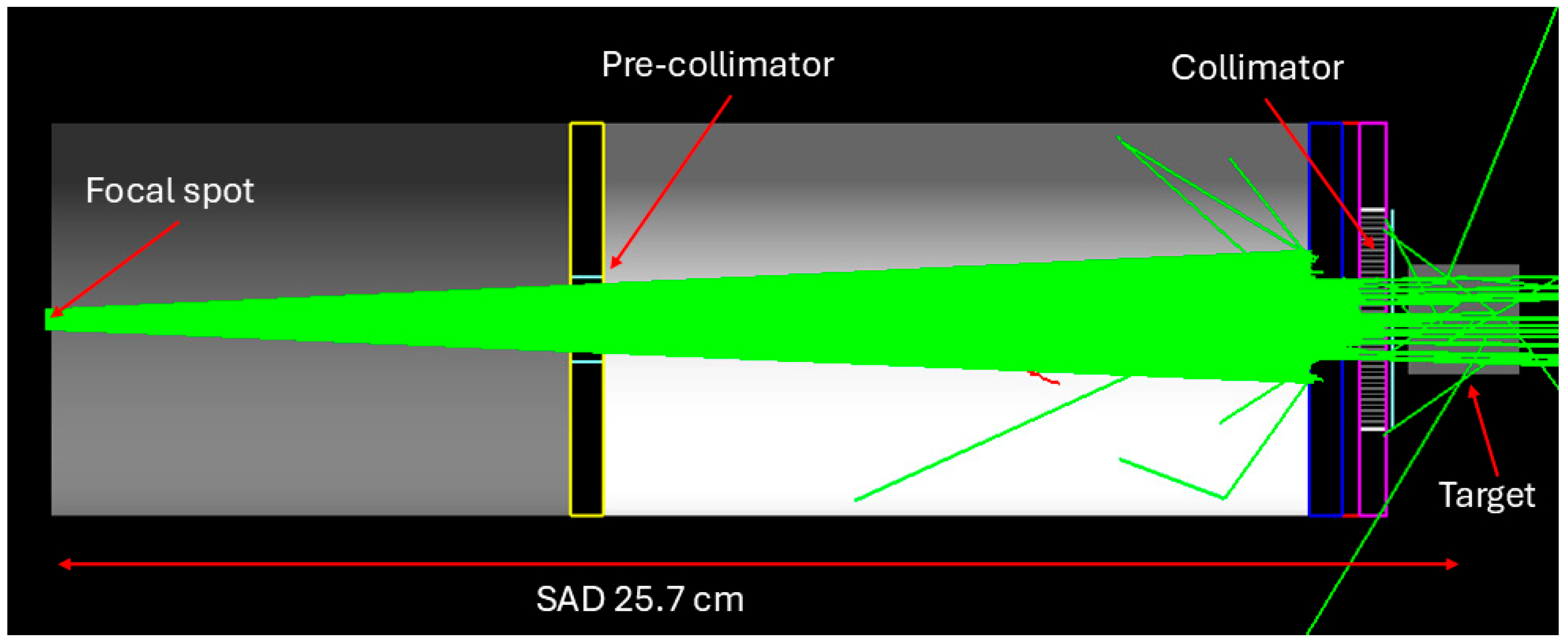
The simulated setup was based on the small-animal irradiator X-RAD225Cx SmART (Precision X-Ray Irradiation, North Branford, CT, USA) available at the Preclinical Imaging Facility of the San Raffaele Scientific Institute, Milan, Italy. The X-RAD system employs an orthovoltage X-ray tube equipped with a tungsten anode with dual focal-spot sizes (5 mm for treatment and 0.3 mm for imaging), mounted on a rotational C-arm gantry for image-guided preclinical irradiation. For this irradiator, we devised a digital twin (Figure 1) implemented in the MC simulation code and validated in previous work: in that paper, the team at San Raffaele Institute developed a full simulation (in TOPAS v. 3.9) validated via percentage depth dose measurements both in an open beam and with an MBRT collimator using radiochromic dosimetry [16]. The beam went through a device collimator (two lead pre-collimators in Figure 1) and an MBRT collimator. The simulated geometry is reported in Figure 1. The pre-collimators were two 7.1 × 7.1 × 0.6 cm3 lead collimators positioned 9.8 cm and 23.2 cm from the source and with an aperture of 1.44 × 1.44 cm2, respectively, reducing the beam divergence to 6°. The beam field size at the back side of the collimator face was 1.44 × 1.44 cm2. The MBRT collimator was put 23.3 cm from the focal spot. The description of this collimator is reported in Section 2.4.
The tube was operated at 225 kVp and 13 mA, with 2 mm Be inherent filtration and a 0.3 mm Cu additional filter. The corresponding X-ray spectrum for the MC simulations was estimated using SpekCalc [17], based on the specific characteristic of the X-RAD SmART X-ray tube [18]. For the irradiator at San Raffaele Hospital, we measured the focal spot size for the treatment mode (3.5 × 3.2 mm2 FWHM) and the Half-Value Layer (HVL) (0.91 mm Cu). A square focal spot with a side of 3.5 mm was used in the simulation.
The simulated target was a voxelized water cube phantom (2 × 2 × 2 cm3) centered 25.7 cm from the focal spot of the X-ray tube; as a result of our simulations, the 3D dose distribution D(x,y,z) (absorbed dose in target voxels) in the water phantom was calculated, with side cubic voxels of 0.1 mm.

2.2. Simulation Setup

MC simulations were performed using TOPAS (Tool for particle simulation) version 3.9, an extension of Geant4 toolbox version 10.5.p01 designed for applications in medical physics, biology and clinical pre-research [19]. The physics list was built with the Geant4_Modular option using modules recommended for kilovoltage radiotherapy applications (g4em-standard_opt4”, “g4h-phy_QGSP_BIC_HP”, “g4decay”, “g4ion-binarycascade”, “g4h-elastic_HP”, “g4stopping”). For each simulation, 2 × 10¹⁰ primary photons were launched to achieve a statistical uncertainty below 2%. Similar simulation approaches have been successfully employed for collimator optimization in spatially fractionated X-ray setups, confirming the reliability of Geant4-based microdosimetric modeling [12,16].

2.3. Evaluated Parameters

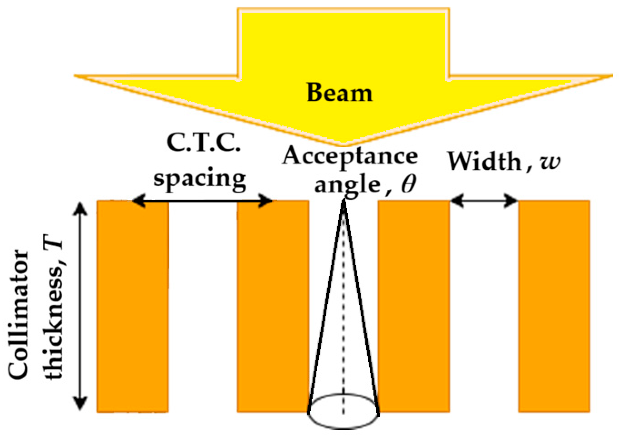
The collimator parameters investigated in the MC simulations included both material (lead and pure tungsten) and geometrical characteristics (Figure 2): center-to-center (CTC) spacing, thickness (T), slit width (w), width-to-center-to-center spacing ratio (w/CTC), and central acceptance angle (θ), as defined by:
θ = tan 1 ( w i d t h 2 × t h i c k n e s s )
All simulations were performed in air. The metrics extracted were the mean dose, peak dose, valley dose, and peak-to-valley dose ratio (PVDR), commonly used to characterize x-MBRT beam quality [6]. Peak and valley doses were calculated by averaging over the three central peaks or valleys, respectively, while the mean dose was obtained by averaging over the full beam size at 1 cm depth in the target. All values were calculated at 1 cm depth within the water phantom. When comparing the (three-dimensional, 3D) dose distributions produced by x-MBRT irradiations (i.e., with the MBRT collimator in the beam path) in the water phantom with those produced by the same irradiations without the x-MBRT collimator, with the same x-y entrance field size (i.e., open-beam irradiation) used, we calculated the MBRT/open beam ratio map, R(x,y,z), of the 3D absorbed dose map (in Gy), DMBRT(x,y,z), obtained with the MBRT collimator, and compared it to the 3D dose map (in Gy) obtained without the collimator, Dopen(x,y,z) (with z being the depth in the phantom):
R ( x , y , z ) = D M B R T ( x , y , z ) D o p e n ( x , y , z ) .
Hence, we calculated the relative dose as the ratio of (MBRT dose)/(open-beam dose) for the fixed X-ray field size, X-ray spectrum, and target-to-collimator distance while changing the CTC spacing, thickness (T), slit width (w), width-to-center-to-center spacing ratio (w/CTC), and central acceptance angle (θ). Relative dose values for x-MBRT irradiations were then always less than unity (i.e., DMBRT/Dopen < 1) due to the attenuation of the primary (divergent) X-ray beam produced by the collimator blades. In this way, using such relative dose values, we highlighted the dependence of x-MBRT dose distributions on the specific features of the collimator under investigation, canceling out the influence of parameters which were common to MBRT and open-beam irradiations.

2.4. MBRT Collimator Setup

2.4.1. Parallel MBRT Collimator

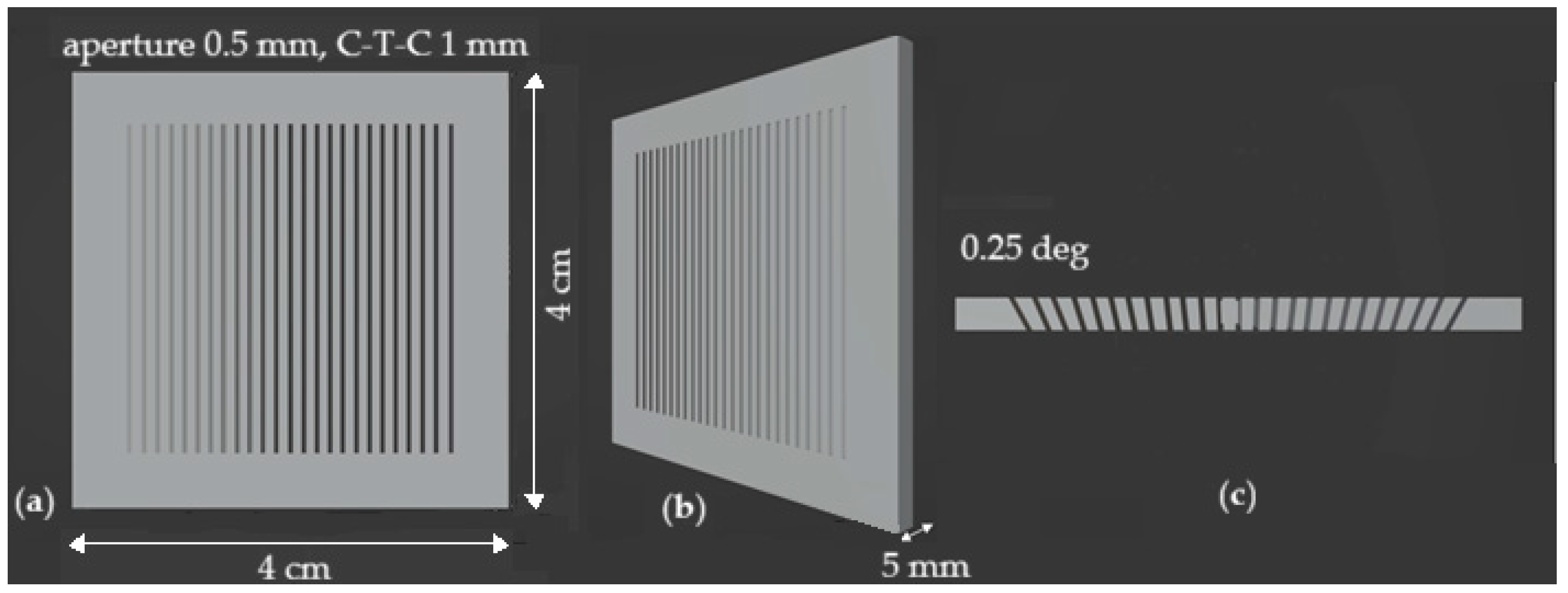
An initial series of simulations was performed using lead and tungsten collimators with parallel slits (Figure 3) to compare their attenuation properties under simplified geometries. These collimators were modeled with a fixed thickness (T = 5 mm) and a CTC = 1 mm, while the ratio w/CTC varied from 10% to 50% in 10% increments. This configuration enabled the evaluation of the beam-opening effects on dose modulation and PVDR. Subsequently, a more comprehensive analysis was performed on tungsten-based MBRT parallel-slit collimators, exploring a wider range of geometrical configurations, in alignment with the literature values [5]. Specifically, T was varied from 1 mm to 5 mm in 1 mm steps; w/CTC ranged from 10% to 50%; and the CTC tested values were 1.0, 1.5, 2.0, and 3.0 mm. In the resulting 3D dose maps evaluated in the water cube, the PVDR, peak dose, valley dose, and mean dose were extracted along lateral dose profiles at 1 cm depth and used as quantitative performance metrics for comparison. This systematic study allowed for assessment of how slit width, spacing, and thickness affect the lateral dose distribution in MBRT. The field size was 1.5 × 1.5 cm2 at the entrance of the water phantom.

2.4.2. Divergent MBRT Collimator

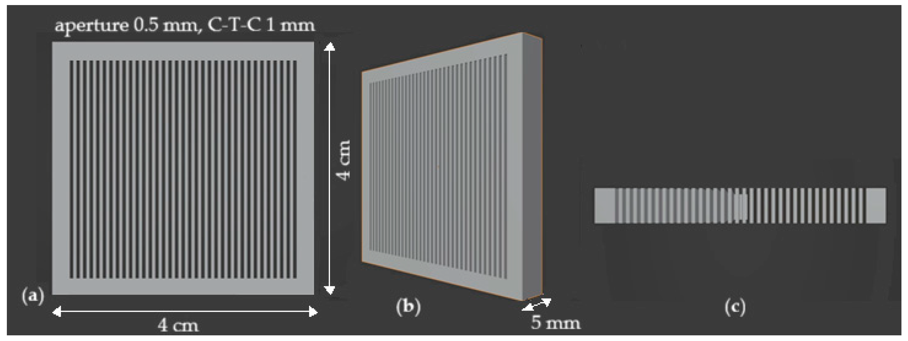
In addition to the parallel geometries, divergent slit tungsten collimators were analyzed (Figure 4). These configurations maintained constant T = 5 mm and CTC = 1 mm, while varying the w/CTC ratio from 10% to 50%.

3. Results

3.1. Influence of Collimator Material

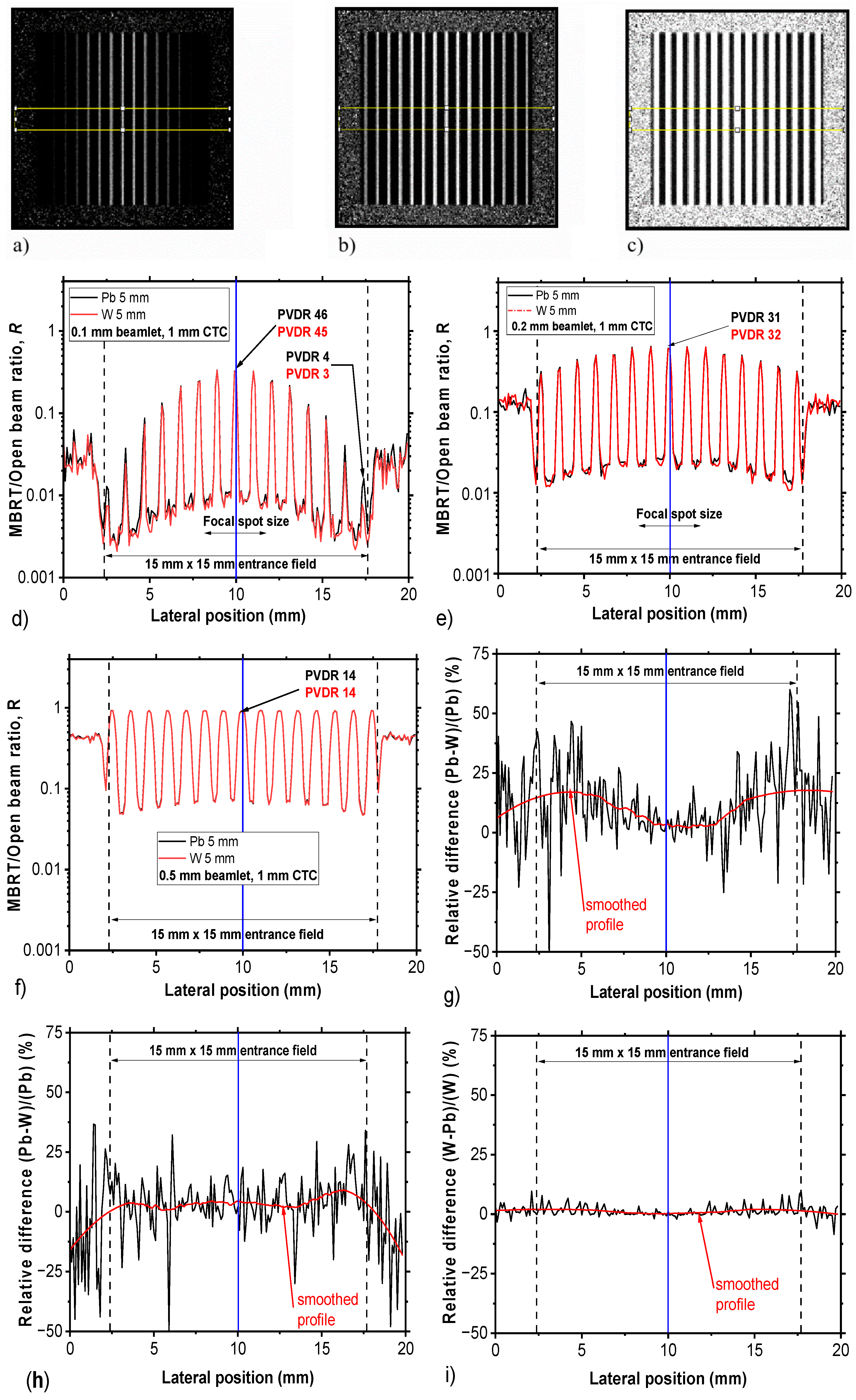
We evaluated the absorbed dose MBRT/open beam ratio maps R(x,y,z) obtained using lead or tungsten MBRT collimators with identical geometrical configurations. Figure 5a–c show the R(x,y,z = 1 cm) distributions in the water phantom at 1 cm depth, obtained using parallel MBRT collimators made of lead and tungsten. Figure 5d–f present the corresponding lateral profiles of R(x,y,z = 1 cm) distributions for collimators with T = 5 mm, CTC = 1 mm, and w/CTC ratios of 10%, 20%, and 50%, respectively. Both materials exhibit characteristic parabolic-shaped profiles in the peak and valley regions due to beam divergence and lateral scattering, which lead to PVDR degradation away from the central axis.
Figure 5g–i report the percentage dose differences between the R(x,y,z = 1 cm) profiles in Figure 5d–f obtained with lead and tungsten collimators, showing the largest deviations for MBRT collimators with smaller apertures. In these cases, the difference profiles display a concave pattern, with minimal variation at the center and maximum lateral discrepancies of approximately 25%, 13%, and 3% for 10%, 20%, and 50% w/CTC ratios, respectively.

3.2. Influence of Collimator’s Geometrical Parameters

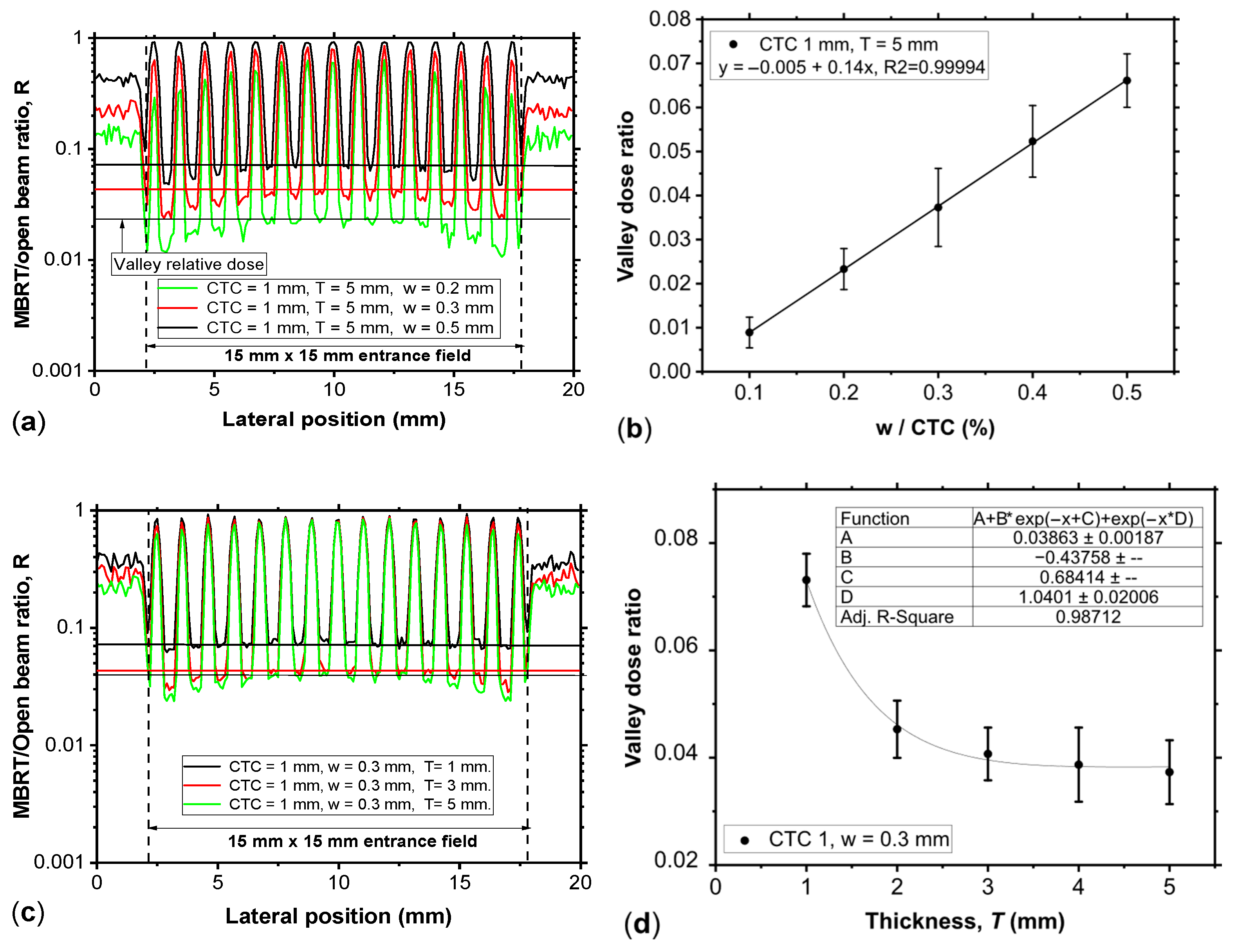
We analyzed the effect of geometric parameters (specifically, collimator thickness T and w/CTC ratio) on the R(x,y,z) distribution using tungsten parallel collimators. Figure 6a shows the R(x,y,z = 1 cm) profiles measured at 1 cm depth in water for T = 5 mm, CTC = 1 mm, and a w/CTC ratio of 20%, 30% and 50% (w = 0.2 mm, 0.3 mm and 0.5 mm, respectively). As illustrated in Figure 6b, the valley dose increases linearly with the w/CTC ratio, a trend consistent across different CTC values. This confirms that the w/CTC ratio, rather than the absolute slit width, influences the valley dose and consequently the PVDR. Figure 6c shows dose profiles for CTC = 1 mm and w/CTC = 30%, while the collimator thickness T is 1 mm, 3 mm, and 5 mm. In this case, the valley dose decreases progressively with increasing thickness T, following an approximately two-exponential-decay trend (Figure 6d).
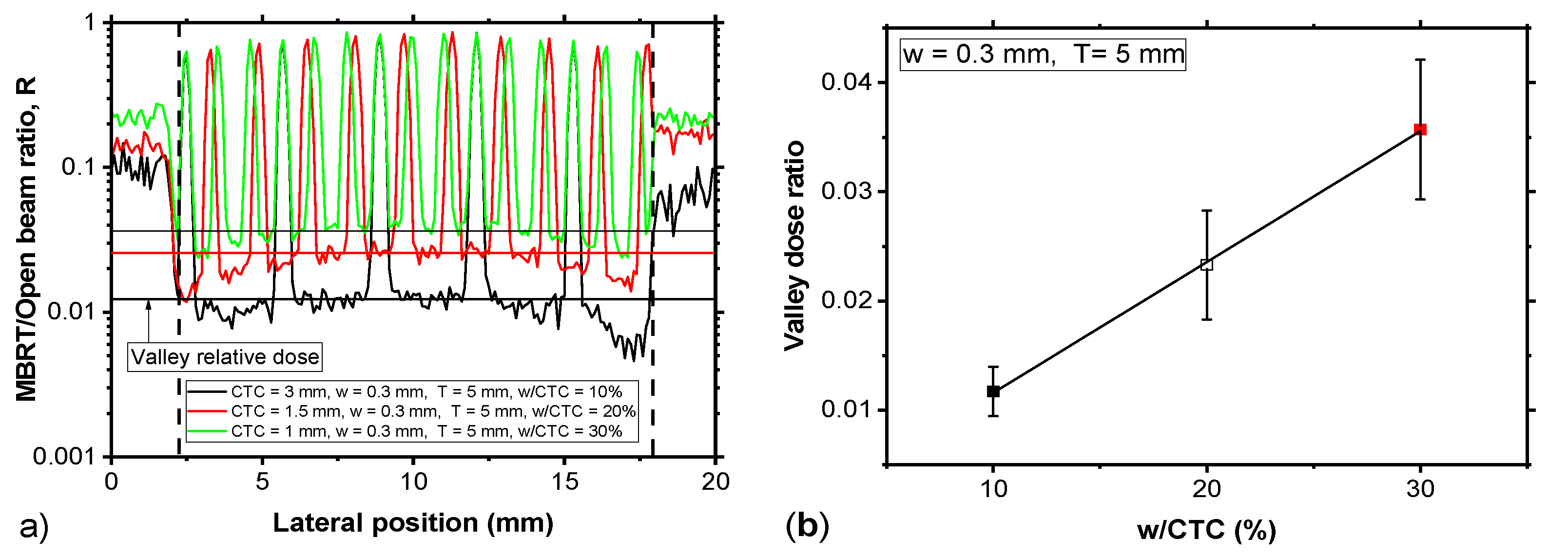
Figure 7a compares the profiles of MBRT/open beam ratio R from collimators with the same nominal aperture (w = 0.3 mm) and thickness T = 5 mm but different CTC distances. The results confirm that the valley dose ratio (evaluated at the level of the three central peaks) depends primarily on the w/CTC ratio rather than on the absolute aperture slit width.
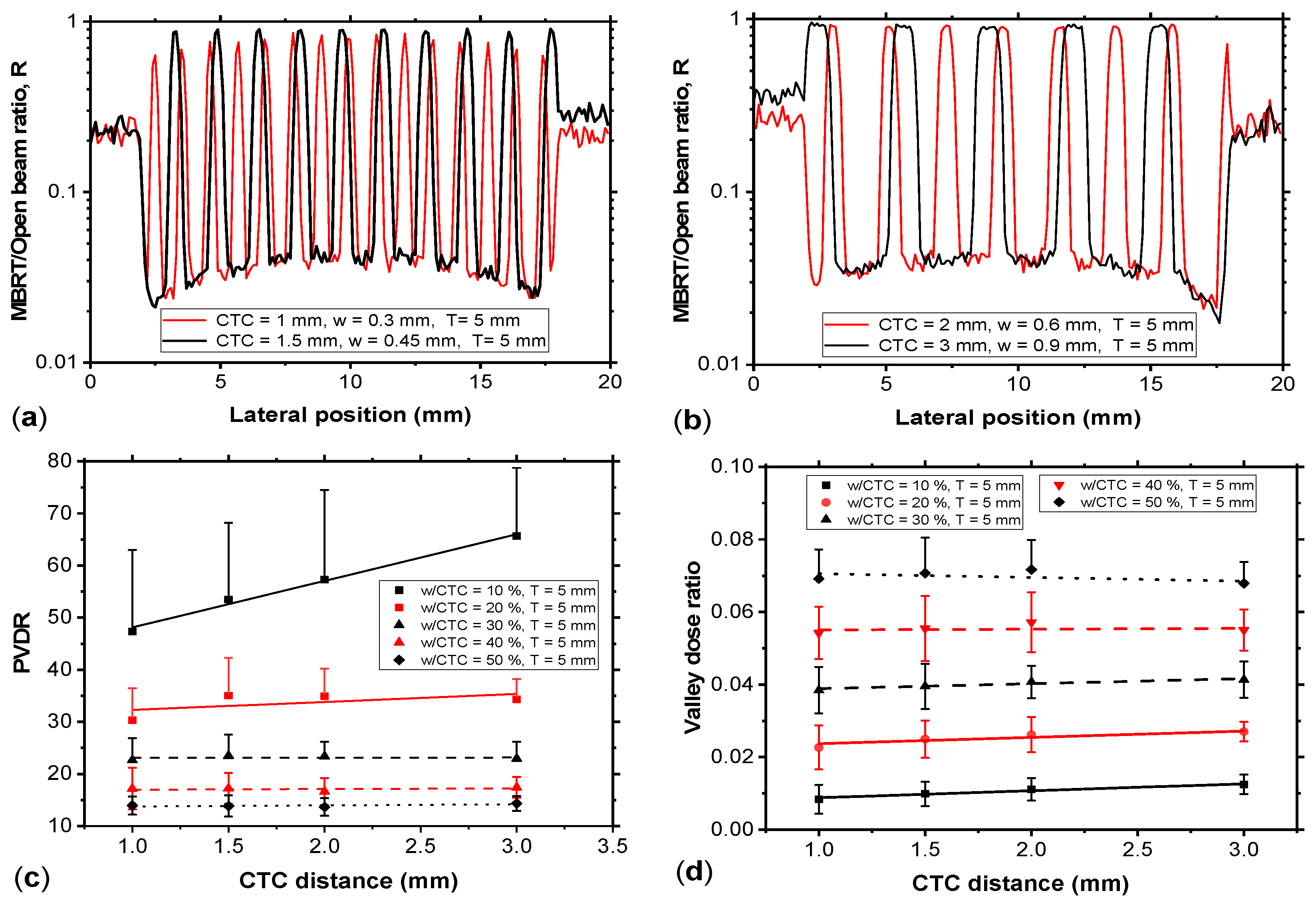
Figure 8a,b show the dose profiles for tungsten parallel collimators with varying CTC distances while maintaining collimator thickness T = 5 mm and w/CTC ratio = 30%. The valley dose remains approximately constant with CTC variations, whereas PVDR increases linearly with CTC for smaller apertures, owing to a rise in the peak dose value. For PVDR calculations, the peak dose is evaluated as the mean of the highest values of the three central peaks.
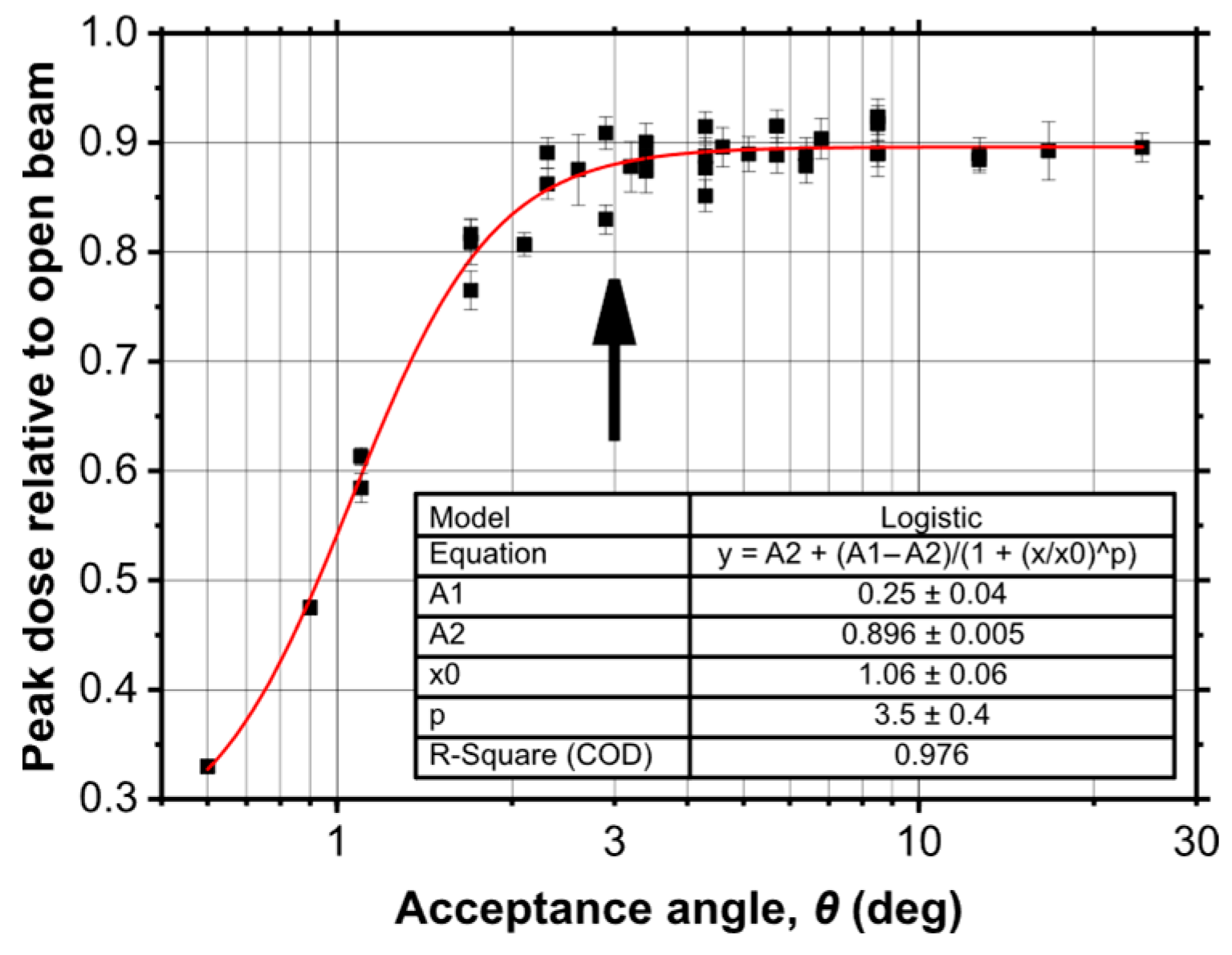
Finally, Figure 9 illustrates that the peak dose increases with the acceptance angle θ until reaching a saturation level of approximately P e a k   d o s e S a t = 0.9 (normalized to the open beam) at θ ≈ 3°, beyond which no further increase is practically observed.

3.3. Influence of Collimator’s Divergence

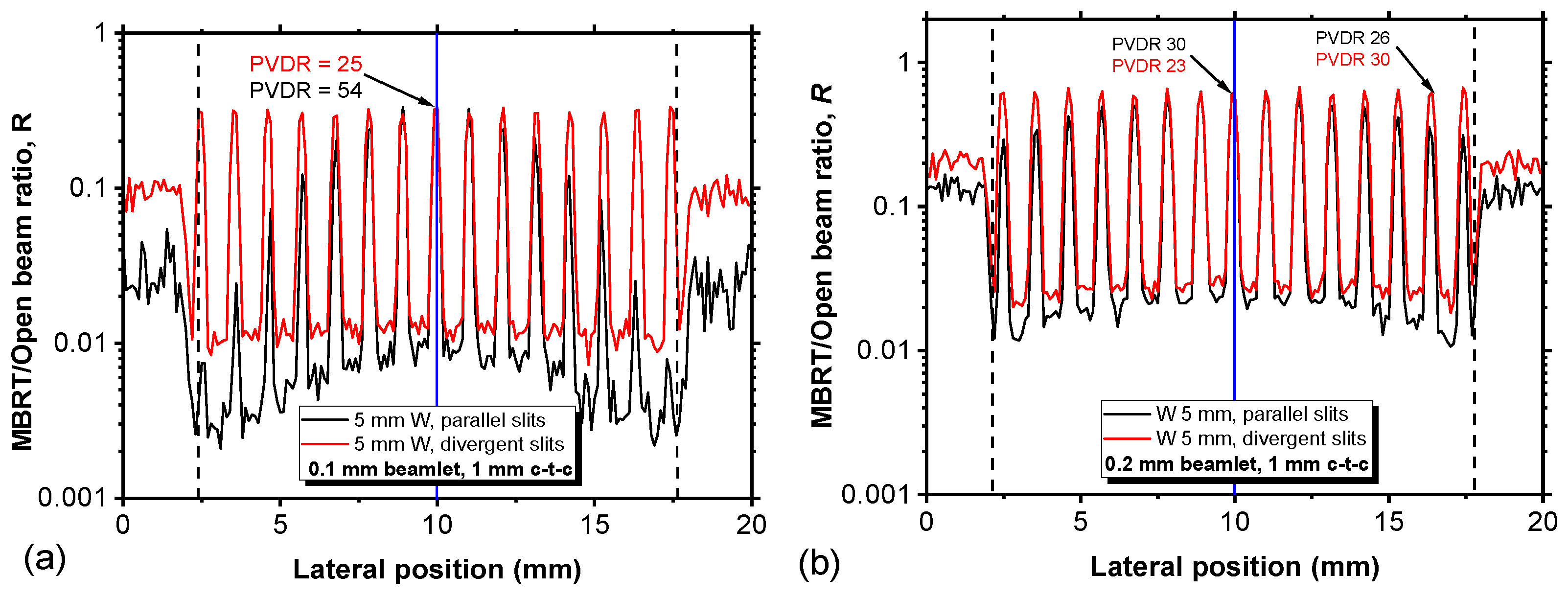
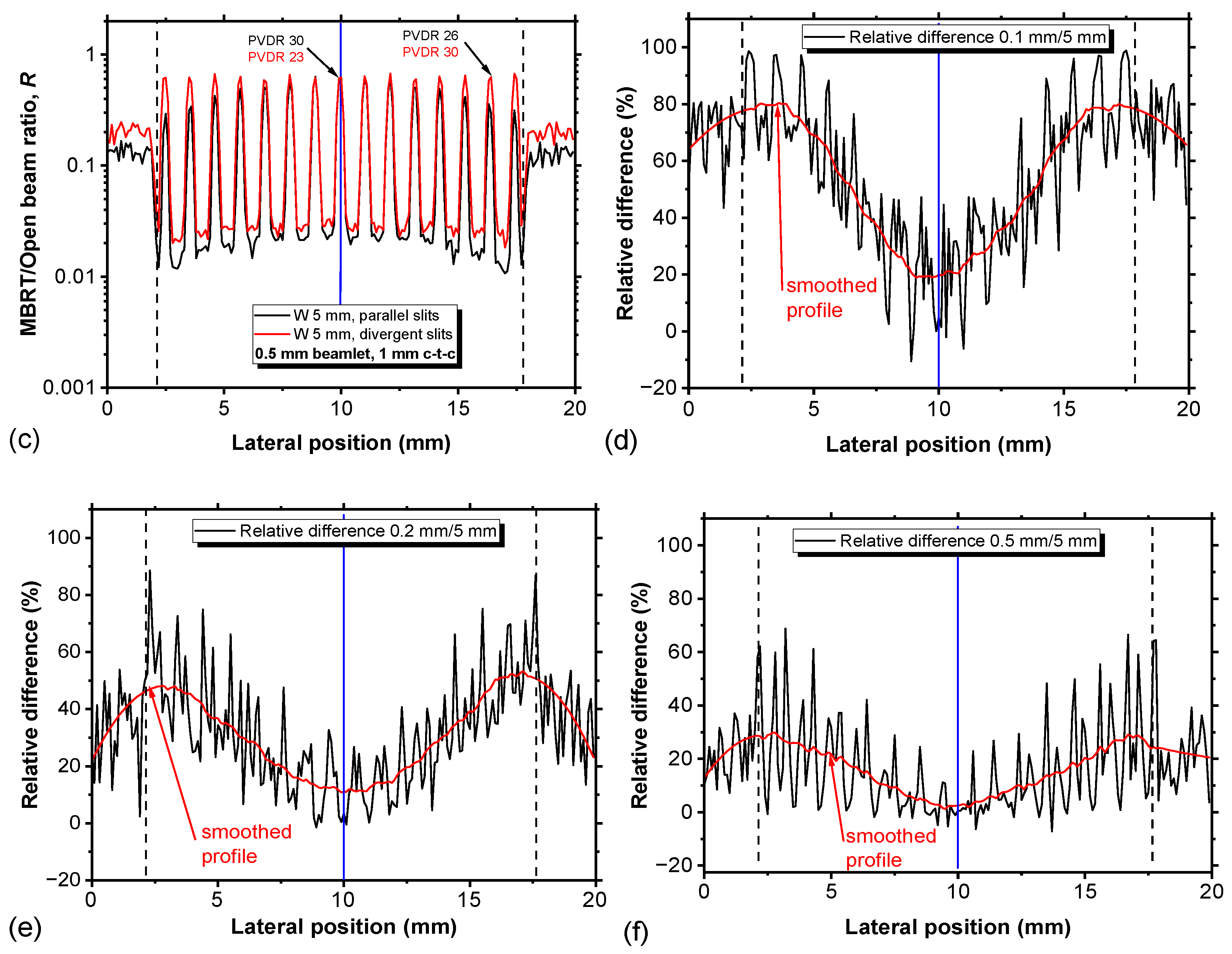
The final part of the analysis investigated the impact of divergent versus parallel collimator geometries on dose distribution. A divergent collimator was defined as one whose slits are aligned with the divergence of the beam. In Figure 10 we compare profiles of MBRT/open beam ratios produced by parallel (black line) and divergent (red line) tungsten MBRT collimators for slit widths of 0.1 mm (Figure 10a), 0.2 mm (Figure 10b) and 0.5 mm (Figure 10c), with CTC = 1 mm and T = 5 mm. Profiles are shown on a logarithmic scale to emphasize differences in low-dose regions. Divergent collimators produce flatter lateral dose profiles, characterized by a reduced intensity fall-off away from the beam’s central axis. However, the corresponding valley doses are consistently higher compared to parallel collimators, resulting in lower PVDR values near the central axis.
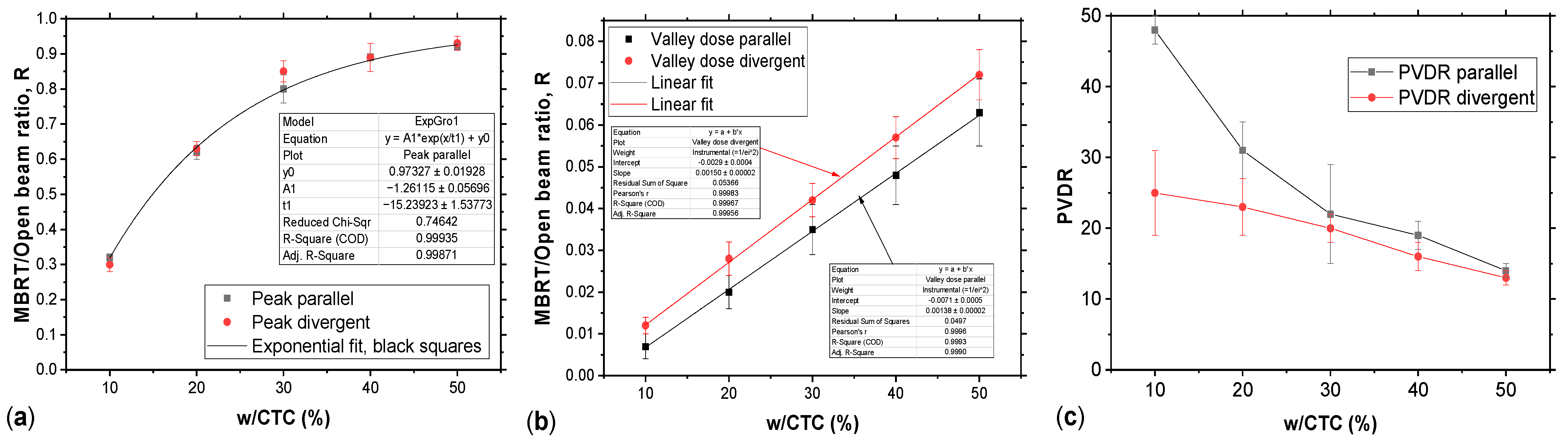
Figure 11a–c summarize these findings:
  • Central peak doses are nearly identical for both geometries.
  • Valley doses are systematically higher for divergent collimators.
  • PVDR values are higher for parallel collimators in the central region, whereas divergent geometries improve lateral uniformity.

4. Discussion

The present work provides a systematic Monte Carlo-based analysis of how individual geometric parameters of multi-slit collimators influence the fundamental dosimetric descriptors of X-ray minibeam radiation therapy. While several studies have explored collimator fabrication strategies or reported empirical performance metrics [12,13,20], a quantitative mapping between geometric design variables and beam-quality indicators such as PVDR, valley dose, and mean dose has remained largely unexplored. The results presented here fill this gap by establishing explicit functional dependencies that can guide rational collimator optimization for preclinical x-MBRT.
The comparison between lead and tungsten collimators (Figure 5) demonstrates that, for thicknesses on the order of 5 mm, both materials yield nearly indistinguishable central-axis PVDR values. This is consistent with the high attenuation coefficients of both materials in the orthovoltage range, where photoelectric absorption dominates. The different profile shapes (Figure 5d–f) due to the parallel collimator geometry show a lateral reduction in the peak intensity from 25% to 2% for the smallest (w/CTC = 10%; Figure 5g) and higher (w/CTC = 50%, Figure 5i) apertures, respectively. This arises from the differential attenuation of the oblique photons’ beam, which becomes increasingly relevant at off-axis positions. This indicates that the choice of material affects the beam shape in the case of a collimator parallel to the variation in the size of the slits.
A central outcome of this study is the demonstration that the valley dose exhibits a linear dependence on the w/CTC ratio (Figure 6b), confirming that the geometric filling factor governs the fraction of scattered photons reaching the interbeam regions. This observation is consistent with theoretical models of spatially fractionated beams, where valley dose is dominated by low-energy scattered photons whose fluence scales with the open fraction of the collimator [5]. Conversely, the two-exponential-decay dependence of valley dose on collimator thickness (Figure 6d) reflects the suppression of lateral photon transport within the slit channel, in agreement with previous Geant4-based analyses of microbeam and minibeam collimators [13,16]. These relationships provide a compact parametric framework for predicting valley dose behavior without requiring full MC simulations for each geometry. They also indicate that the process can be interpreted as being governed by two exponential decay components: one related to the geometric attenuation of scattered radiation (exp(−(T + C))) and the other due to transmission through the collimator walls (exp(−T × D)). In these expressions (with fitting coefficients C and D), C represents an effective distance from the collimator exit to the point of measurement (accounting for the depth in the phantom and scattering geometry) and T × D represents the effective thickness of collimator walls.
Thicker collimators more effectively suppress laterally scattered photons within the slits, thereby increasing PVDR. However, beyond approximately 4 mm (for tungsten), additional thickness yields diminishing returns while unnecessarily reducing beam transmission and increasing manufacturing complexity and costs—particularly for tungsten.
The acceptance angle θ emerges as another critical determinant of peak dose transmission. As shown in Figure 9, the peak dose increases with θ until reaching a saturation plateau at approximately 0.9 (normalized to open beam) for θ ≳ 3°. This behavior reflects the interplay between the intrinsic beam divergence of the X-RAD225Cx source and the angular acceptance of the slit channel. When θ is smaller than the beam divergence, a portion of the primary fluence is intercepted by the collimator walls, reducing the peak intensity. Once θ matches or exceeds the beam divergence, further increases do not enhance transmission. Similar saturation effects have been reported in synchrotron-based MRT studies, where matching the collimator acceptance to the source divergence is essential to preserve peak integrity [4,5].
The dependence of PVDR on CTC spacing (Figure 7 and Figure 8) further clarifies the geometric trade-offs inherent to MBRT design. For fixed w/CTC ratios, increasing CTC enhances PVDR primarily through an increase in peak dose, while valley dose remains approximately constant. This is consistent with the reduced overlap of lateral scatter tails from adjacent beamlets at larger separations, a phenomenon also observed in proton and electron minibeam configurations [2,3]. However, excessively large CTC values reduce the spatial frequency of the minibeam pattern, potentially diminishing the biological benefits associated with spatial fractionation [4,9]. Thus, the optimal CTC must balance dosimetric modulation with biological efficacy.
From these findings, empirical relationships can be derived to guide the collimator’s design optimization:
D v a l l e y   w / C T C
D v a l l e y   A + B × e T + C + e D × T
D p e a k θ 0.9 ,   f o r   θ 3 °
P V D R θ C T C w , f o r   θ 3 °
P V D R θ T 2 ,   f o r   θ 3 °
The comparison between parallel and divergent collimators (Figure 10 and Figure 11) further clarifies the trade-offs between geometric configurations. When slit width, thickness, and spacing are matched, both geometries yield similar central peak doses (Figure 11a). However, divergent collimators produce flatter lateral profiles (Figure 10a–c), improving field uniformity but increasing valley dose due to enhanced transmission of scattered photons. These findings are consistent with prior MRT studies showing that divergent geometries increase the contribution of scattered photons to the valley region due to improved alignment between the slit channel and the beam divergence [5]. As a result, PVDR is consistently higher for parallel collimators (Figure 11c), making them more suitable for applications where strong spatial modulation and normal-tissue sparing are prioritized. Nevertheless, beams exhibiting strong lateral inhomogeneities could be advantageous during the planning phase, similarly to the use of flattening filter-free (FFF) beams, which have been shown to improve dose delivery efficiency and treatment conformity [20]. Divergent geometries may instead be advantageous for larger irradiation fields where uniformity is desired, although they inherently constrain the focus-to-target distance, reducing flexibility in experimental setups.
Overall, the present results suggest that intermediate geometries (i.e., collimator thicknesses of 2–4 mm and w/CTC ratios of 20–40%) offer a favorable compromise between PVDR, transmission efficiency, and manufacturability. These findings are consistent with the parameter ranges adopted in successful preclinical x-MBRT studies [4,6,11]. Importantly, the relationships derived here provide a basis for future treatment-planning strategies, including integration into GPU-accelerated MC platforms such as VIT-MBRT [14,15], enabling rapid optimization of collimator designs tailored to specific biological endpoints, beam qualities, and anatomical targets.
It should be noted that the relationships derived in this work should be interpreted as empirical dependencies valid within the parameter space investigated in our Monte Carlo simulations. The results are obtained for a specific photon spectrum, collimator material, and irradiation geometry, and therefore their applicability to substantially different conditions cannot be assumed a priori. In particular, for significantly different photon spectra (e.g., high-energy bremsstrahlung or gamma radiation), the dominant photon interaction mechanisms shift from photoelectric absorption to Compton scattering, which can substantially modify the photon transmission through the collimator walls and the relative contribution of scattered radiation to the valley dose.
Similarly, changes in collimator material, phantom depth, or beam energy may alter both the proportionality constant in the relationship D v a l l e y w / C T C and the observed dependencies on collimator thickness and beam incidence angle. A systematic investigation of these effects, including the dependence on beam spectrum, photon energy, and collimator material, is beyond the scope of the present work and will be addressed in future studies.
Future work will also include experimental validation of the MC-estimated dose maps using radiochromic film dosimetry to resolve the microbeam dose structure and determine the PVDR, complemented by micro-ionization chamber measurements for absolute dose calibration and for average dose measurements (e.g., valley dose) in irradiation conditions where volume averaging effects are negligible [21]. Given the increasing interest in clinical translation of x-MBRT [11,22], establishing robust, physics-based design criteria for collimators is essential for ensuring reproducible and biologically effective dose delivery.

5. Conclusions

This study presented a systematic Monte Carlo-based analysis of minibeam collimator geometries for an MBRT investigation in small animals using a preclinical X-ray irradiator. The simulations of various metal collimators investigated the influence of collimator material, slit width, CTC spacing, thickness, and geometry on the dose-to-water distribution in a water phantom representative of small-animal experiments. Expressing the dose maps in relative terms with respect to open-beam irradiation permits linking MBRT absorbed dose fields to open field beams, whose dosimetry is already available to the experimenter through the irradiator’s preclinical treatment-planning system. Results showed that the valley dose was found to increase linearly with the width-to-spacing ratio (w/CTC) and to decrease approximately with the two-exponential-decay trend of the collimator thickness, establishing the role of these two parameters as geometric determinants of spatial modulation in x-MBRT. The peak dose saturated for acceptance angles around 3°, confirming that collimator divergence should be matched to the beam geometry to minimize unnecessary attenuation or valley overexposure. Parallel geometries preserved higher PVDR and stronger spatial modulation, whereas divergent geometries offered smoother lateral profiles, making them more suitable for large irradiation fields. Overall, intermediate configurations, with thicknesses between 2 and 4 mm and w/CTC ratios of 20–40%, emerged as the most balanced design window, combining efficient dose modulation, acceptable transmission, and practical manufacturability. However, the optimal geometry remains application-specific, determined by the intended biological endpoint and specific experimental setup.

Author Contributions

Conceptualization, P.R. and G.M.; methodology, P.R.; software, U.C. and N.L.; validation, U.C., N.L., L.A.C., G.M. and P.R.; formal analysis, U.C.; writing—original draft preparation, U.C. and P.R.; writing—review and editing, U.C., G.M., N.L., L.A.C., R.P. and P.R.; supervision, G.M. and P.R.; project administration, G.M. and R.P. All authors have read and agreed to the published version of the manuscript.

Funding

This research was funded in the framework of the PNRR project “Sviluppo e ottimizzazione della radioterapia con mini fasci a raggi X” (PNRR-POC-2022-12376062) and INFN VITA5 project.

Institutional Review Board Statement

Not applicable.

Informed Consent Statement

Not applicable.

Data Availability Statement

The raw data supporting the conclusions of this article will be made available by the authors on request.

Acknowledgments

All simulations carried out using the CPU-based and the GPU-accelerated resources of INFN (Istituto Nazionale di Fisica Nucleare), Italy. This work also contributes to the project VITA5 (Virtual Imaging TriAls) funded by INFN. Thanks are due to the authors’ colleagues at San Raffaele Scientific Institute (Milan, Italy) (A. Spinelli and C. Fiorino) for the useful discussions and exchange of information within the PNRR MBRT project.

Conflicts of Interest

The authors declare no conflicts of interest.

Abbreviations

The following abbreviations are used in this manuscript:
CTCCenter-To-Center Distance
MBRTMinibeam Radiation Therapy
MRTMicrobeam Radiation Therapy
PVDRPeak-To-Valley Dose Ratio
SFRTSpatially Fractionated Radiation Therapy
VITVirtual Imaging Trial

References

  1. Griffin, R.J.; Ahmed, M.M.; Amendola, B.; Belyakov, O.; Bentzen, S.M.; Butterworth, K.T.; Chang, S.; Coleman, C.N.; Djonov, V.; Formenti, S.C.; et al. Understanding High-Dose, Ultra-High Dose Rate, and Spatially Fractionated Radiation Therapy. Int. J. Radiat. Oncol. Biol. Phys. 2020, 107, 766–778. [Google Scholar] [CrossRef] [PubMed]
  2. Yan, W.; Khan, M.K.; Wu, X.; Simone, C.B., II; Fan, J.; Gressen, E.; Zhang, X.; Limoli, C.L.; Bahig, H.; Tubin, S.; et al. Spatially fractionated radiation therapy: History, present and the future. Clin. Transl. Radiat. Oncol. 2020, 20, 30–38. [Google Scholar] [CrossRef] [PubMed]
  3. Prezado, Y.; Grams, M.; Jouglar, E.; Martínez-Rovira, I.; Ortiz, R.; Seco, J.; Chang, S. Spatially fractionated radiation therapy: A critical review on current status of clinical and preclinical studies and knowledge gaps. Phys. Med. Biol. 2024, 69, 10TR02. [Google Scholar] [CrossRef] [PubMed]
  4. Sotiropoulos, M.; Brisebard, E.; Le Dudal, M.; Jouvion, G.; Juchaux, M.; Crépin, D.; Sebrie, C.; Jourdain, L.; Labiod, D.; Lamirault, C.; et al. X-rays minibeam radiation therapy at a conventional irradiator: Pilot evaluation in F98-glioma bearing rats and dose calculations in a human phantom. Clin. Transl. Radiat. Oncol. 2021, 27, 44–49. [Google Scholar] [CrossRef] [PubMed]
  5. McGarrigle, J.M.; Long, K.R.; Prezado, Y. On the significance of the different geometrical and dosimetric parameters in microbeam and minibeam radiation therapy: A retrospective evaluation. Front. Oncol. 2024, 14, 1449293. [Google Scholar] [CrossRef] [PubMed]
  6. Prezado, Y.; Thengumpallil, S.; Renier, M.; Bravin, A. X-ray energy optimization in minibeam radiation therapy. Med. Phys. 2009, 36, 4897–4902. [Google Scholar] [CrossRef] [PubMed]
  7. Fernandez-Palomo, C.; Chang, S.; Prezado, Y. Should Peak Dose Be Used to Prescribe Spatially Fractionated Radiation Therapy?—A Review of Preclinical Studies. Cancers 2022, 14, 3625. [Google Scholar] [CrossRef] [PubMed]
  8. Garcia, D.A.; Fazzari, J.M.; Hlushchuk, R.; Khoma, O.Z.; Bakken, K.K.; Burgenske, D.M.; Lester, S.C.; Mutter, R.W.; Lucien, F.; Remmes, N.B.; et al. Minibeam radiation therapy valley dose determines tolerance to acute and late effects in the mouse oral cavity. Int. J. Radiat. Oncol. Biol. Phys. 2025, 123, 262–269. [Google Scholar] [CrossRef] [PubMed]
  9. Prezado, Y.; Lamirault, C.; Larcher, T.; Gilbert, C.; Espenon, J.; Patriarca, A.; de Marzi, L.; Corvino, A.; Ortiz, R.; Juchaux, M. On the significance of peak dose in normal tissue toxicity in spatially fractionated radiotherapy: The case of proton minibeam radiation therapy. Radiother. Oncol. 2025, 205, 110769. [Google Scholar] [CrossRef] [PubMed]
  10. Bazyar, S.; Inscoe, C.R.; O’Brian, E.T.; Zhou, O.; Lee, Y.Z. Minibeam radiotherapy with small animal irradiators: In vitro and in vivo feasibility studies. Med. Phys. 2020, 47, 4879–4887. [Google Scholar] [CrossRef] [PubMed]
  11. Grams, M.P.; Quintero, C.; Mashayekhi, M. Minibeam Radiation Therapy Treatment (MBRT): Commissioning and First Clinical Implementation. Int. J. Radiat. Oncol. Biol. Phys. 2024, 120, 1423–1434. [Google Scholar] [CrossRef] [PubMed]
  12. Herchko, S.; Yaddanapudi, S.; Wang, C.K.C. Design and validation of a minibeam treatment delivery system for use with a radiation therapy research platform. Biomed. Phys. Eng. Express 2025, 11, 047001. [Google Scholar] [CrossRef] [PubMed]
  13. Babcock, K.; Sidhu, N.; Kundapur, V.; Ali, K. Collimator design for experimental minibeam radiation therapy. Med. Phys. 2011, 38, 2192–2197. [Google Scholar] [CrossRef] [PubMed]
  14. Mettivier, G.; Luongo, N.; Crimaldi, U.; Pacelli, R.; Clemente, S.; Oliviero, C.; Lai, Y.; Jia, X.; Cerbone, L.A.; Fiorino, C.; et al. VIT-MBRT, a GPU-based virtual imaging platform dedicated to minibeam radiation therapy for preclinical research. In Proceedings Virtual Imaging Trials in Medicine; Bakic, P., Bliznakova, K., Bosmans, H., Carton, A.-K., Glick, S., Frangi, A., Kinahan, P., Maidment, A., Samei, E., Sechopoulos, I., et al., Eds.; Zenodo: Geneva, Switzerland, 2025; p. 36. [Google Scholar] [CrossRef]
  15. Buffardi, E.; Cerbone, L.A.; Crimaldi, U.; Franciosini, G.; Schiavi, A.; Patera, V.; Russo, P.; Mettivier, G. FREDem: A multi GPU Monte Carlo simulation code for virtual imaging trials in radiology. In Proceedings Virtual Imaging Trials in Medicine; Bakic, P., Bliznakova, K., Bosmans, H., Carton, A.-K., Glick, S., Frangi, A., Kinahan, P., Maidment, A., Samei, E., Sechopoulos, I., et al., Eds.; Zenodo: Geneva, Switzerland, 2025; p. 170. [Google Scholar] [CrossRef]
  16. Koksal Akbas, C.; Vurro, F.; Fiorino, C.; Cozzarini, C.; Cavaliere, F.; Milani, P.; Broggi, S.; Del Vecchio, A.; Di Muzio, N.; Tacchetti, C.; et al. Preclinical photon minibeam radiotherapy using a custom collimator: Dosimetry characterization and preliminary in-vivo results on a glioma model. Phys. Medica 2024, 124, 103420. [Google Scholar] [CrossRef] [PubMed]
  17. Poludniowski, G.; Landry, G.; DeBlois, F.; Evans, P.M.; Verhaegen, F. SpekCalc: A program to calculate photon spectra from tungsten anode x-ray tubes. Phys. Med. Biol. 2009, 54, N433–N438. [Google Scholar] [CrossRef] [PubMed]
  18. Poludniowski, G.G. Calculation of x-ray spectra emerging from an x-ray tube. Part II. X-ray production and filtration in x-ray targets. Med. Phys. 2007, 34, 2175–2186. [Google Scholar] [CrossRef] [PubMed]
  19. Faddegon, B.; Ramos-Méndez, J.; Schümann, J.; McNamara, A.; Shin, J.; Perl, J.; Paganetti, H. The TOPAS Tool for Particle Simulation, a Monte Carlo Simulation Tool for Physics, Biology and Clinical Research. Phys. Med. 2020, 72, 114–121. [Google Scholar] [CrossRef] [PubMed]
  20. Pellicioli, P.; Donzelli, M.; Davis, J.A.; Estève, F.; Hugtenburg, R.; Guatelli, S.; Petasecca, M.; Lerch, M.L.F.; Bräuer-Krisch, E.; Krisch, M. Study of the X-ray radiation interaction with a multislit collimator for the creation of microbeams in radiation therapy. J. Synchrotron Radiat. 2021, 28, 392–403. [Google Scholar] [CrossRef] [PubMed]
  21. Ahmed, M.; Beyreuther, E.; Gantz, S.; Horst, F.; Meyer, J.; Pawelke, J.; Schmid, T.E.; Stolz, J.; Wilkens, J.J.; Bartzsch, S. Design and dosimetric characterization of a transportable proton minibeam collimation system. Front. Oncol. 2024, 14, 1473625. [Google Scholar] [CrossRef] [PubMed]
  22. Bräuer-Krisch, E.; Adam, J.-F.; Alagoz, E.; Bartzsch, S.; Crosbie, J.; DeWagter, C.; Dipuglia, A.; Donzelli, M.; Doran, S.; Fournier, P.; et al. Medical physics aspects of the synchrotron radiation therapies: Microbeam radiation therapy (MRT) and synchrotron stereotactic radiotherapy (SSRT). Phys. Medica 2015, 31, 568–583. [Google Scholar] [CrossRef] [PubMed]
Figure 1. The Monte Carlo simulations were performed in TOPAS, with the geometry shown, using custom-designed MBRT collimators that fit within the 15 × 15 mm2 field collimator of the X-ray irradiator. Dose distribution was scored in a digital 2 × 2 × 2 cm3 water phantom with 0.1 × 0.1 × 0.1 mm3 voxels; the source-to-object distance was 25.7 cm.
Applsci 16 03282 g001
Figure 2. Schematic representation of the minibeam geometry in x-MBRT. The primary beam is spatially fractionated into narrow beamlets by a multi-slit metal collimator, characterized by a single aperture width w, center-to-center (CTC) aperture distance and collimator thickness (T). The central beamlet (with respect to the central axis of the X-ray beam) has an acceptance half-angle θ .
Applsci 16 03282 g002
Figure 3. Geometry of a parallel collimator: (a) front view, (b) 45° view, and (c) transversal section.
Applsci 16 03282 g003
Figure 4. Geometry of a divergent collimator: (a) front view, (b) 45° view, and (c) transversal section.
Applsci 16 03282 g004
Figure 5. Example of the R(x,y,z = 1 cm) distribution (evaluated on the x-y plane at z = 1 cm depth in water; 15 × 15 mm2 field size at the entrance surface of the water phantom) produced by tungsten parallel MBRT collimators: 5 mm thick; 1 mm CTC. Beamlet width: (a) 0.1 mm, (b) 0.2 mm, (c) 0.5 mm. The profiles obtained with similar MBRT collimators but different materials (tungsten: red line; lead: black line) are shown in panels (df). In (gi) the relative differences between the profiles in (df) are reported.
Applsci 16 03282 g005
Figure 6. (a) Comparison of profiles of the R(x,y,z = 1 cm) distribution (at 1 cm depth in water; 15 × 15 mm2 field size at the entrance surface of the water phantom) produced by tungsten MBRT collimators with collimator thickness of 5 mm; CTC of 1 mm; and w of 0.2 mm, 0.3 mm and 0.5 mm. (b) Valley dose ratio as a function of the w/CTC ratio. (c) Comparison of profiles of the R(x,y,z) distribution (at 1 cm depth in water; 15 × 15 mm2 field size at the entrance surface of the water phantom) produced by tungsten MBRT collimators with collimator thicknesses of 1 mm, 3 mm and 5 mm; w = 0.3 mm and; CTC distance of 1 mm. (d) Valley dose ratio as a function of thickness T. A two-exponential-decay trend was fitted to the data points.
Applsci 16 03282 g006
Figure 7. (a) Profiles of the MBRT/open beam ratio produced by parallel tungsten MBRT collimators (at 1 cm depth in water; 15 × 15 mm2 field size at the entrance surface of the water phantom) for a slit width of 0.3 mm; thickness of 5 mm; and CTCs of 3 mm (thick black line), 1.5 mm (thick red line) and 1 mm (fine black line). (b) Valley dose ratio as a function of w/CTC.
Applsci 16 03282 g007
Figure 8. (a) Profiles of the MBRT/open beam ratio produced by parallel tungsten MBRT collimators (at 1 cm depth in water; 15 × 15 mm2 field size at the entrance surface of the water phantom) for a thickness of 5 mm, CTC of 1 mm, and slit width of 0.3 mm (red line) and CTC of 1.5 mm and slit width of 0.45 mm (black line); (b) profiles with a CTC of 2 mm and slit width of 0.6 mm (red line) and a CTC of 3 mm and slit width of 0.9 mm (black line); (c) PVDR as a function of CTC distance for several w/CTC ratios; (d) valley dose as a function of CTC distance for several w/CTC ratios.
Applsci 16 03282 g008
Figure 9. Calculated data for relative peak dose as a function of the collimator acceptance angle (please note the horizontal log scale). A logistic fit is shown. The peak dose for the x-MBRT irradiation (relative to open-beam irradiation) reaches a saturation level equal to 0.9 (minibeam dose with respect to open-beam irradiation dose) for an acceptance angle of about 3° (black arrow) or higher.
Applsci 16 03282 g009
Figure 10. Profiles of the MBRT/open beam ratios produced by parallel (black line) and divergent (red line) tungsten MBRT collimators (at 1 cm depth in water; 15 × 15 mm2 field size at the entrance surface of the water phantom) for slit widths of 0.1 mm (a), 0.2 mm (b) and 0.5 mm (c). In all collimators the collimator thickness is fixed at 5 mm and the distance CTC at 1 mm. Relative differences between the parallel and divergent MBRT collimators profile are reported in (df).
Applsci 16 03282 g010aApplsci 16 03282 g010b
Figure 11. (a) Peak dose as a function of the w/CTC ratio for parallel and diverging collimators. (b) Valley dose curve for parallel and diverging collimators as a function of the w/CTC ratio. Note that the values for the diverging collimator are always higher than those for the parallel counterpart. (c) Central PVDR curve for parallel and diverging collimators as a function of the w/CTC ratio.
Applsci 16 03282 g011
Disclaimer/Publisher’s Note: The statements, opinions and data contained in all publications are solely those of the individual author(s) and contributor(s) and not of MDPI and/or the editor(s). MDPI and/or the editor(s) disclaim responsibility for any injury to people or property resulting from any ideas, methods, instructions or products referred to in the content.