1. Project Overview
1.1. Project Overview
With the planning and construction of various high-rise and super-high-rise buildings, along with the development of ultra-long inclined-shaft tunnels, the volume of one-time concrete pouring has rapidly increased, and the requirements for continuous pouring have become increasingly stringent. Large-volume concrete projects involving tens of thousands of cubic meters of concrete are emerging in increasing numbers. Meanwhile, the characteristics of concrete pouring, such as long distances, significant elevation differences, and numerous site constraints, have led to a series of construction challenges, including the difficulty of rapid pouring for large-volume, high-drop concrete and the complexity of construction organization. The continuous rapid pouring technology for ultra-long-distance, high-drop concrete, as well as wear resistance of the pouring pipes, pose significant challenges.
This project was implemented at the Luoning Pumped Storage Power Station, featuring a single-stage 1000 m inclined shaft for water diversion. Considering the narrow space, high construction difficulty, and steep slope (38°) of the lower part of the shaft, self-compacting concrete was used for backfilling to prevent safety hazards caused by overlapping concrete vibration and placement operations. Currently, three concrete transportation methods are employed for ultra-long inclined shafts: hopper rail transport, chute concrete, and pipe concrete. The project adopted the pipe concrete transportation method. To meet the requirements for self-compacting backfill concrete placement in the lower steel-lined section, challenges such as aggregate segregation during long-distance concrete delivery and pipe wear must be addressed.
1.2. The Significance of the Research
During concrete discharge and transportation, the aggregate and slurry experience different stress conditions and movement speeds. When the conveying distance exceeds the critical threshold, separation occurs between aggregate and slurry, resulting in segregation. Furthermore, the relative motion between the slurry and pipe walls causes aggregate and slurry to impact the pipe surfaces, leading to erosion, wear, and even concrete blockage. These issues severely compromise concrete pouring efficiency and quality, jeopardizing the structural stability and construction safety of water-diversion-inclined shafts. To enable rapid construction and efficient pouring in ultra-long inclined shafts, studying the concrete discharge process is crucial. This research helps control concrete segregation, enhance pipe wear resistance, and ensure both safety and cost-effectiveness in such engineering projects.
Researchers have conducted extensive studies on technologies such as concrete sliding and the design of concrete chutes both domestically and internationally, as exemplified by He H.Y. [
1], Tang J.C. [
2], Peng Z.H. [
3], Wang X.Y. [
4], Wang H. [
5], Liao G.L. [
6], Wang Q. [
7], Fan C.X. [
8], Zhou S.H. [
9], Zhang W.G. [
10], Shi A.J. [
11], Liu X. [
12], Zhang J.T. [
13], Yu H.S. [
14], Zhao R.J. [
15], Lai X.W. [
16], Wang G.W. [
17], and Liu S.H. [
18]. However, there is relatively little research on the design of concrete sliding and chutes for ultra-long distances on steep slopes.
In the construction or design of inclined shaft or tunnel projects in the past, due to the high probability of pipe blockage, fast wear, and separation of concrete aggregates in long-distance transportation of concrete chutes, short-distance (≤300 m) and gentle-slope (≤25°)-inclined shaft technology were mostly used, and concrete chute transportation was relatively easy to achieve [
19,
20]. Previously, steel pipes were used as conveying pipelines for concrete transportation on steep slopes and ultra-long inclined shafts. The main problems with using steel pipes were: (1) the weight of the steel pipes was too high, making construction difficult on steep slopes and increasing construction costs; and (2) due to the fast sliding speed of concrete on slopes, the wear of steel pipes was severe. It is difficult to replace damaged steel pipes on steep slopes, which delays the construction period and increases costs. Researchers in [
21,
22] have also conducted research on UHPC boards and pipes, using FRP-reinforced UHPC materials that exhibit excellent bending, compressive performance, and wear resistance. They have been widely used in the transportation of ores or airport runways. The research goal of the concrete chute in this project is to develop a lightweight and wear-resistant chute for the special steep slope construction environment.
This project adopts two types of chute schemes, fiberglass reinforced plastic + alumina ceramic sheets, and ultra-high polymer wear-resistant materials, mainly to solve the problem of concrete chute discharge on steep slopes and ultra-long inclined shafts. To solve the problem of difficult construction on steep slopes, lightweight, high-strength, and wear-resistant pipelines were used to reduce construction difficulty and make it easier for construction personnel to operate. To solve the problems of fast concrete sliding speed and severe wear of the chute in ultra-long-distance-inclined shafts. To solve the problem of pipe blockage or pipeline damage replacement. Due to the use of lightweight and high-strength materials, the replacement speed is fast, reducing delays in the construction period.
1.3. Research Content
This paper aims to deeply and systematically study the application of the pipe sliding technology in the construction process. Through the analysis of its applicable scope, the concrete performance requirements, the comparative analysis of the pipe shape, the selection of the pipe wear-resistant material, etc., a set of mature concrete sliding construction method for the ultra-long distance and high drop was formed.
- (1)
Determine the mix proportion of pumped concrete to prevent segregation during the discharge process.
- (2)
Determine the diameter, thickness, and length of the chute to meet the construction requirements for manual work on steep slopes (38°)
- (3)
Determine the wear-resistant material, thickness, and wear loss of the inner wall of the chute.
2. The Design of Concrete Sliding Pipe for Inclined Shaft for Water Diversion
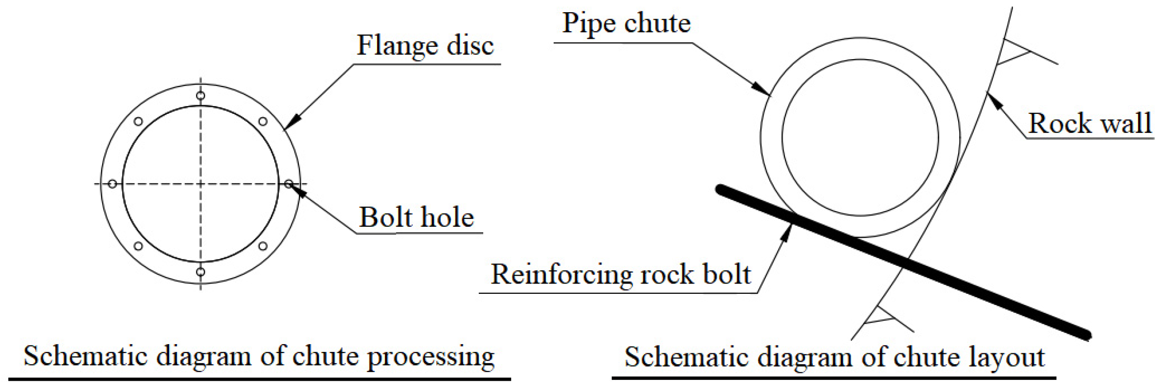
The concrete construction for the steel pipe-lined section of the inclined shaft water diversion system commenced after the pressure steel pipe installation. The 60 m long inclined shaft section adopted the “shaft mouth chute + receiving port + D200 fiberglass pipe + stringer” method for concrete placement. Flanges were installed at both ends of the fiberglass pipes connected via bolts. On the right side of the shaft cross-section, 0.5 m long D25 reinforced anchor rods with 0.25 m rock penetration were arranged. The fiberglass pipes were welded to these anchor rods using flanges, while the flanges were securely fastened with wire. D200 mm wear-resistant fiberglass pipes were installed along the shaft’s vertical concrete placement sections. The concrete was transported vertically through steel pipe chutes, with the chutes removed as the pouring progressed. To ensure construction safety and efficiency, the fiberglass pipes were partially embedded in the concrete. Since the fiberglass pipes followed the shaft’s sidewalls, each 6 m section featured stringers at the ends to prevent aggregate segregation. Buffer devices were installed 30 m from the discharge port and 18 m from the storage bin, as detailed in
Figure 1.
3. The Analysis of Concrete Anti-Segregation
The calculation of concrete anti-segregation performance based on the Bingham model is mainly to judge whether the paste can resist aggregate settlement and bleeding by quantifying the reasonable range of yield stress (τ0) and plastic viscosity (η). τ0 should be large enough to balance the weight of aggregate, and η should be moderate to consider the fluidity and water retention.
The τ0 and η of fresh concrete were measured by coaxial cylinder rheometer under standard conditions (temperature 20 ± 2 °C, static time 5 ± 1 min, and shear rate 50~100 s−1), and the τ0 and η of fresh concrete were obtained.
The Bingham parameter threshold criteria: the segregation resistance parameters vary across concrete types and should be determined based on the engineering requirements. Commonly used reasonable ranges are listed in
Table 1.
The project site employs self-compacting concrete, which is delivered through a chute pipe from the inclined shaft support tunnel to the bottom for pouring. The mix design of the self-compacting concrete is detailed in
Table 2.
The initial laboratory test (20 °C, 5 min) of the Bingham parameters: reference value τ01 = 40 Pa and reference value η1 = 250 Pa·s.
- (1)
Shear Rate Correction
The pumping shear rate γ was set at 300 s−1 (with reference value γ of 50 s−1).
According to the formula:
The shear thinning coefficient: δ = 0.2.
- (2)
Thixotropic Recovery Correction (resting time 30 min)
According to the formula:
The parameters: α = 0.3 (concrete), β = 0.02 min
−1, and t = 30 min.
Finally, after modification, the parameters τ0 = 45.41 Pa and η = 160.4 Pa·s are within the threshold, and the anti-segregation performance can be determined to meet the requirements.
In the actual construction, in order to control the quality of each concrete slip, we conduct spot checks on each batch of mixed concrete and conduct laboratory tests. Based on the results of the laboratory tests, we quickly make correction calculations to ensure that the yield stress, τ, and plastic viscosity, η, of the corrected calculation are within the threshold range, and to ensure the anti-segregation performance of the concrete.
Furthermore, through formulas (1) and (3), we can calculate the yield stress, τ, and plastic viscosity, η, of each batch of the concrete sampling test within the range of [26.4, 61.6] and [233.8, 623.4], respectively, which can ensure that the concrete has good anti-segregation performance.
4. The Selection of Wear-Resistant Materials
The characteristics of concrete pouring for the diversion inclined shaft are as follows:
- (1)
The 38° steep slope makes standing impossible for workers, severely hindering construction progress.
- (2)
Extended concrete placement periods, with each continuous pouring session lasting up to 3 days for 80 m.
- (3)
Replacing the slide pipe is challenging, as it not only increases workload but also delays project timelines. In case of pipe blockage or rupture, all operations must be halted for pipe cleaning and replacement.
To reduce the difficulty and workload of the large-slope operation and the difficulty of changing the chute tube, it is urgent to have one or several kinds of chute tube with light weight, high strength, and strong wear resistance. Under the condition of meeting the requirements of wear resistance and impact resistance, the lighter the weight of each section of concrete chute, the better. The optimization analysis shows that the optimal diameter and length of the concrete chute are obtained. After reading a lot of literature and field investigation, two kinds of chute tube design schemes were selected, mainly nano alumina ceramic wear-resistant tube and ultra-high molecular wear-resistant chute tube.
4.1. Wear-Resistant Chute Pipe of Nano Alumina
Alumina wear-resistant ceramic sheet is a wear-resistant ceramic material with alumina (Al
2O
3) as the main component, where the alumina content is 95%. It is mainly used for components that require corrosion resistance, wear resistance, and high-temperature tolerance. The performance parameters of the ceramic sheet are listed in
Table 3.
The ceramic tile has the following advantages:
- (1)
Exceptional wear resistance: alumina ceramic materials feature high hardness, effectively resisting wear and tear to extend equipment lifespan, making them ideal for high-wear environments.
- (2)
High impact resistance: the alumina ceramic patch, processed through specialized techniques, exhibits excellent impact resistance and maintains stability even under high-intensity impacts.
- (3)
Corrosion resistance: alumina ceramic patches are resistant to acids, alkalis, and chemical corrosion, making them ideal for use in corrosive environments such as chemical plants and metallurgical facilities.
- (4)
Lightweight quality: compared to metal materials, alumina ceramic patches are lighter, reducing equipment load and energy consumption.
- (5)
Easy installation: ceramic tiles are easy to cut and install, allowing flexible adjustments as needed to minimize downtime.
- (6)
High-temperature resistance: the alumina ceramic patch maintains stable performance in high-temperature environments, making it suitable for high-temperature applications.
- (7)
Cost-effectiveness: despite the higher initial investment, its durability and minimal maintenance requirements make it a cost-effective long-term solution.
- (8)
Reduced maintenance: enhanced wear and corrosion resistance significantly lowers equipment maintenance frequency and costs.
- (9)
Efficiency boost: reducing equipment wear and downtime helps enhance production efficiency.
- (10)
Wide applicability: suitable for various industries, including mining, power generation, chemical processing, and metallurgy, with particularly notable performance on heavily worn equipment, as illustrated in
Figure 2.
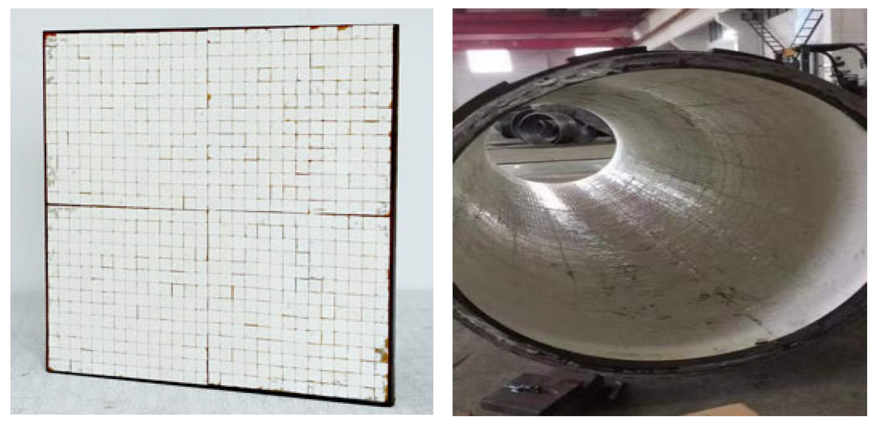
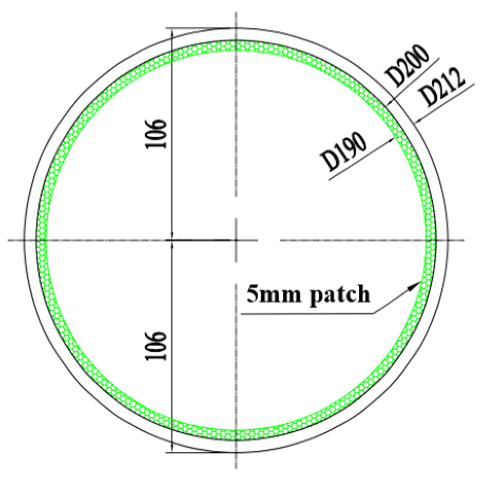
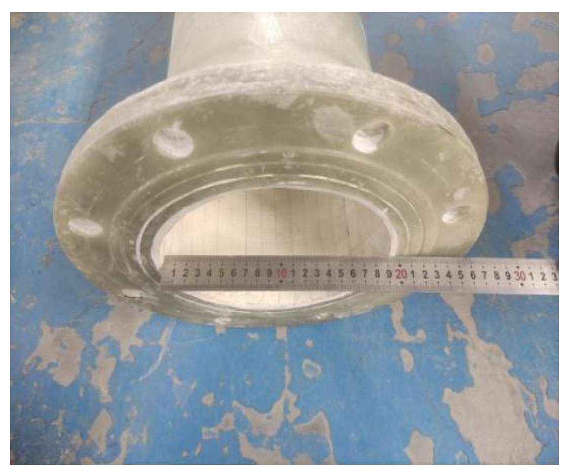
The wear-resistant alumina chute in this project was designed as a glass-fiber-reinforced plastic with an inner diameter of D200 and an outer diameter of D212. The interior of the chute was pasted with 4 mm thick alumina ceramic sheets, with glue thickness of 6 mm. Each section is 1.5 m long, and the total weight is 39.5 kg. The interior of the chute was pasted with 5 mm thick alumina ceramic sheets, with glue thickness of 6 mm. Each section was 1.5 m long, and the total weight was 41 kg. Each section was connected by flanges. The design details are shown in
Figure 3, and the production products are shown in
Figure 4.
4.2. Ultra-High Molecular Wear-Resistant Chute
Ultra-high molecular weight polyethylene (UHMW-PE) is a thermoplastic engineering plastic with an average molecular weight exceeding 2.5 million, synthesized through the polymerization of ethylene and butadiene monomers under catalytic conditions. This material demonstrates exceptional comprehensive properties, including the highest wear resistance, low-temperature tolerance, corrosion resistance, self-lubrication, and impact resistance among all plastics (as shown in
Table 4). Capable of long-term operation within a wide temperature range of −269 °C to +80 °C, UHMW-PE combines the advantages of various plastics such as wear resistance, impact resistance, self-lubrication, corrosion resistance, low-temperature performance, hygienic non-toxicity, non-adhesion, and water resistance. As an ideal pipe material, it finds extensive applications in metallurgical and mining industries (slurry transportation and grouting backfilling), power generation (fly ash transportation), dredging and sand extraction (slurry transportation for lake dredging and sand extraction pipes for dredging vessels), petroleum, natural gas, food processing (grain transportation), chemical, mechanical, and electrical industries.
The “Research Report on Wear Testing of Plastic Pipes” by the Beijing Nonferrous Metallurgical Design and Research Institute points out: the following four different materials of pipes were tested under the same pipe diameter, flow rate, test material, and concentration conditions. The results show that the average annual wear thickness of glass-fiber-reinforced polypropylene pipes is 11.5424 mm/years; engineering-grade polypropylene pipes (PP) 13.5828 mm/years; ultra-high molecular weight polyethylene pipes (UHMW-PE) 5.0104 mm/years; and steel pipes (A3) 36.2424 mm/years. The test results indicate that the wear resistance of ultra-high molecular weight polyethylene (UHMW-PE) pipes is seven times that of steel pipes (A3).
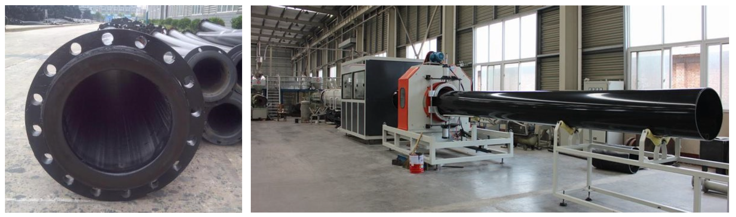
The ultra-high molecular weight (UHMW) wear-resistant pipeline features a unique molecular structure that delivers exceptional anti-slip friction and lightweight properties. With a specific gravity of merely 1/8th that of steel pipes, it simplifies loading/unloading, transportation, and installation while reducing manual labor. UHMW-PE pipes exhibit remarkable aging resistance, maintaining performance for up to 50 years. Suitable for both above-ground overhead and underground burial applications, they can be installed through welding or flange connections, providing safe, reliable, and efficient solutions without corrosion protection, thus demonstrating the “energy-saving, eco-friendly, cost-effective, and high-performance” advantages of UHMW PE pipes. Production and engineering applications of these wear-resistant pipes are illustrated in
Figure 5 and
Figure 6.
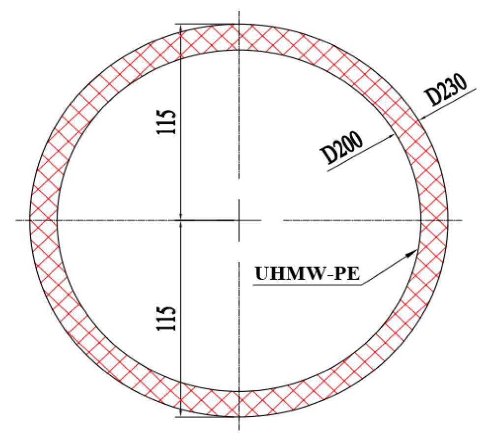
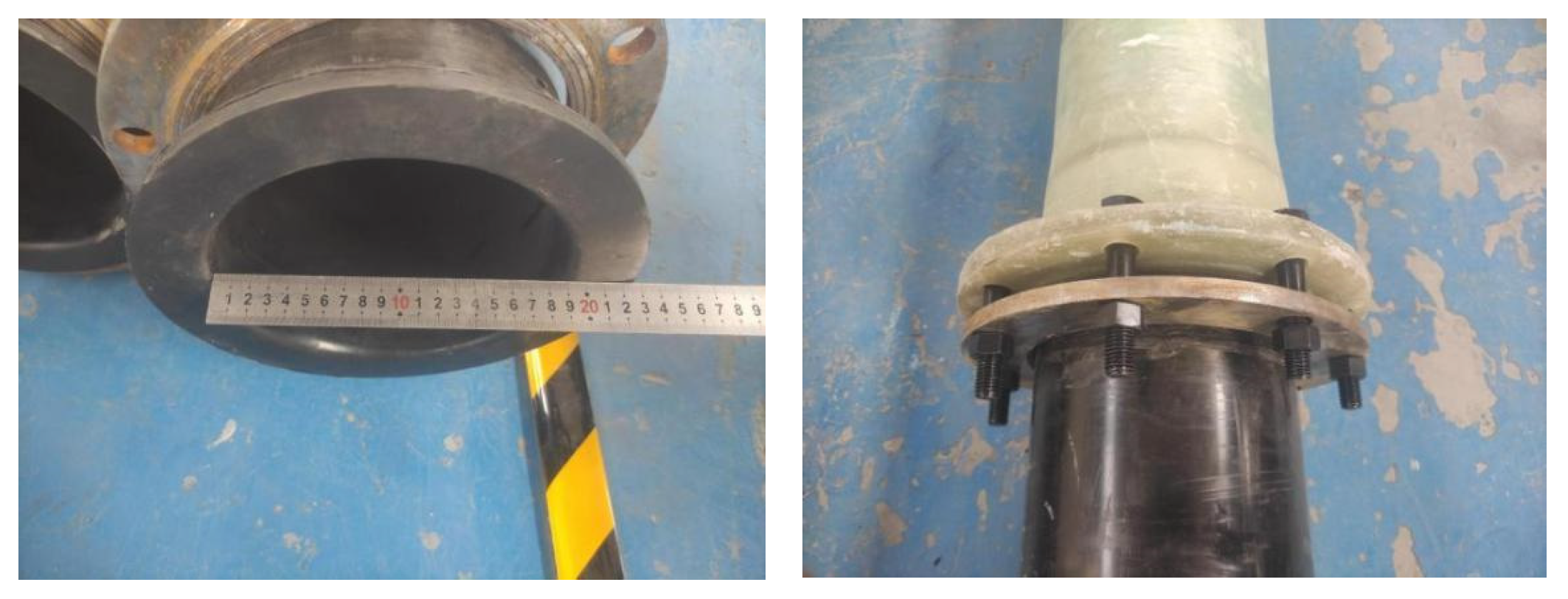
The ultra-high molecular wear-resistant chute is designed with an inner diameter of D200, an outer diameter of D230, a wall thickness of 15 mm, each section being 3.0 m long, and each section weighing 35.5 kg. Each section is connected using a flange plate. The design details are shown in
Figure 7, and the production products are shown in
Figure 8.
4.3. Test Research on the Abrasion-Resistant Sliding Tube
4.3.1. Sample Parameters
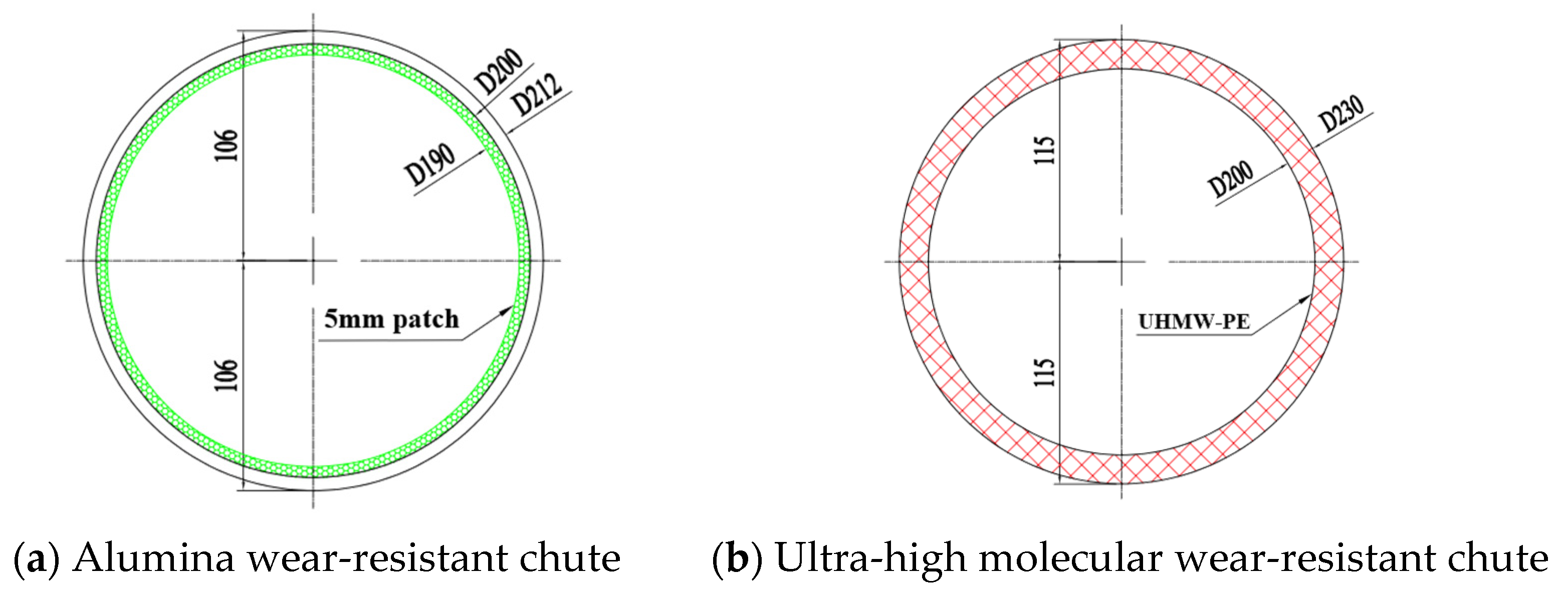
The test specimens are the alumina wear-resistant chute D212 and the ultra-high molecular wear-resistant chute D230. The alumina wear-resistant chute D212 specimen has an inner diameter of 200 mm, an outer diameter of 212 mm, a rubber thickness of 6 mm, and a lining of 4–5 mm on the inner wall of the pipe. Each section is 1.5 m long, with 41 kg weighs; the ultra-high molecular wear-resistant chute D230 specimen has an inner diameter of 200 mm, an outer diameter of 230 mm, a wall thickness of 15 mm, each section is 3.0 m long, with 35.5 kg weighs. The cross-sectional dimensions of the specimens are shown in
Figure 9.
4.3.2. Test Principle
- (1)
Test description:
Wear testing comprises two approaches: field testing and laboratory testing. Field testing replicates or closely approximates actual operating conditions, yielding reliable results though requiring extended durations. Laboratory testing, by contrast, is more time-efficient and cost-effective, with better control over variables, yet its conditions often diverge significantly from real-world scenarios, resulting in outcomes that may not fully represent actual conditions. This study employs laboratory testing to evaluate wear on pipeline inner walls.
- (2)
Test principle:
The wear resistance of materials is usually expressed by the amount of wear. The smaller the amount of wear, the better the wear resistance. There are two methods of measuring the amount of wear: the weighing method and the dimensional method. The weighing method involves weighing the sample or parts before and after wear; the dimensional method involves measuring the sample or parts before and after wear.
Data calculation formula:
Wear amount per unit area (W):
where m
1 is the initial weight of the sample (g), m
2 is the weight of the sample after testing (g), and A is the initial area of the sample (mm
2).
4.3.3. Test Equipment and Testing Protocol
- (1)
Composition of the experimental apparatus:
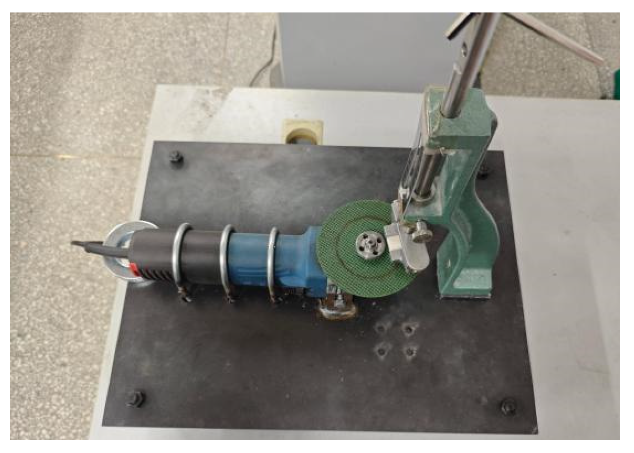
The grinding wheel wear test apparatus is designed according to GB/T12988 “Test Method for Wear Performance of Inorganic Floor Materials,” [
31] and it is also used for the determination of ceramic materials’ wear performance at room temperature. The schematic diagram of the grinding wheel wear experiment device is shown in
Figure 10.
- (2)
The specific steps of the experiment are as follows:
① Prepare alumina ceramic sample and ultra-high molecular weight polyethylene sample, labeled as ceramic sample 1–3 and ultra-high molecular weight polyethylene sample 1–3 respectively.
② The mass of ceramic sample and ultra-high molecular sample was weighed and recorded respectively.
③ Place the ceramic sample between the ceramic sample holder and the grinding wheel. Adjust the height of the ceramic sample holder to maintain a safe distance between them, ensuring the grinding wheel does not contact the ceramic sample holder while securely holding it in place. Rotate the pressure adjustment screw downward to apply spring force, pressing the ceramic sample tightly against the grinding wheel.
④ Turn on the power switch to start the rotation of the boron nitride grinding wheel, and the grinding wheel and ceramic plate begin to rub against each other.
⑤ After 2 min, turn off the power, remove the ceramic sample, weigh the remaining mass and record it, and then calculate the wear amount per unit area.
⑥ Repeat the above steps five times and draw the linear fitting graph of the time–unit area wear according to the experimental data of the ceramic sample obtained.
⑦ Replace the ultra-high molecular sample and repeat the above experimental steps to obtain the linear fitting graph of the time–unit area wear of the ultra-high molecular sample.
⑧ The wear resistance of ceramic samples is better than that of ultra-high molecular samples, which is indicated by the slope of the straight line in the graph of time versus unit area.
4.3.4. Test Phenomena and Result Analysis
The grinding wheel wear test:
(a) The appearance of the alumina ceramic is worn out.
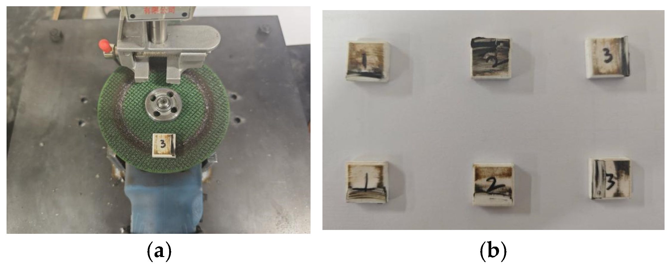
Alumina ceramic disks demonstrate exceptional wear resistance due to their high hardness. During wear testing, the disks exhibited outstanding durability. Post-experiment inspection revealed black scratches on all ceramic surfaces caused by friction-induced heat, with significant marks also appearing on the grinding wheel. The ceramic disks remained hot after testing, and some showed corner fractures. Overall, the ceramic disks exhibited high wear resistance, minimal wear rates, and negligible weight loss. The wear appearance of the ceramic disks is illustrated in
Figure 11.
(b) The appearance of ultra-high molecular weight (UHMW) panels shows signs of wear:
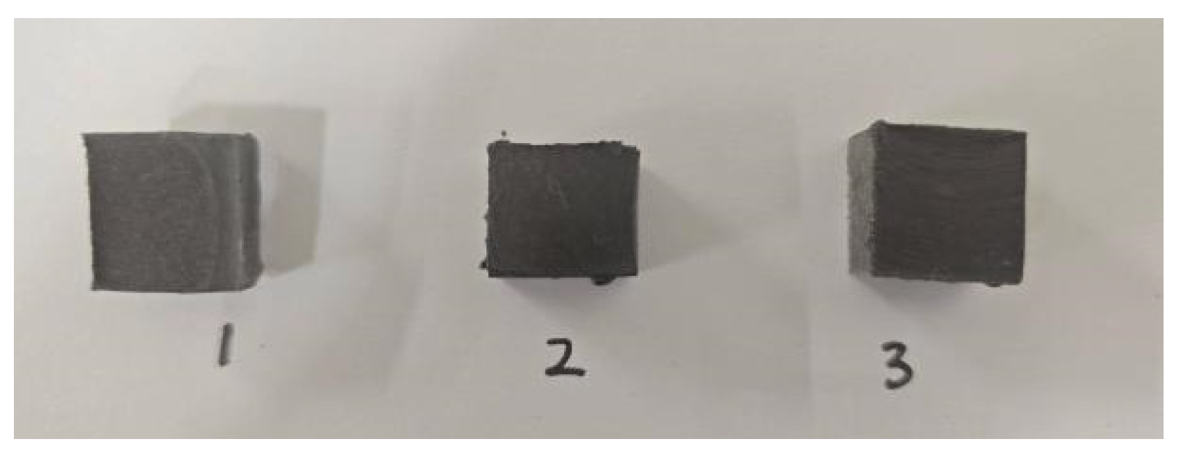
Ultra-high molecular wear-resistant materials demonstrate exceptional durability due to their high hardness. During wear tests, these materials exhibited outstanding resistance. Post-experiment inspection revealed that all wear-resistant plates developed black scratches on their surfaces caused by friction-induced heat, with the grinding wheel also showing deep scratches. The process was accompanied by noticeable particle splashing, and the plates remained hot after testing. Some plates exhibited uneven surfaces. Overall, these ultra-high molecular wear-resistant plates showed superior wear resistance, with slightly higher wear rates than ceramic plates but reduced weight loss. The wear appearance of these plates is illustrated in
Figure 12.
- (1)
Test data:
The alumina ceramic sample and the ultra-high molecular sample were selected and named as ceramic sample and ultra-high molecular sample respectively. The wear amount per unit area was calculated according to Formula 5, and the results are shown in
Table 5.
- (2)
The analysis of test results:
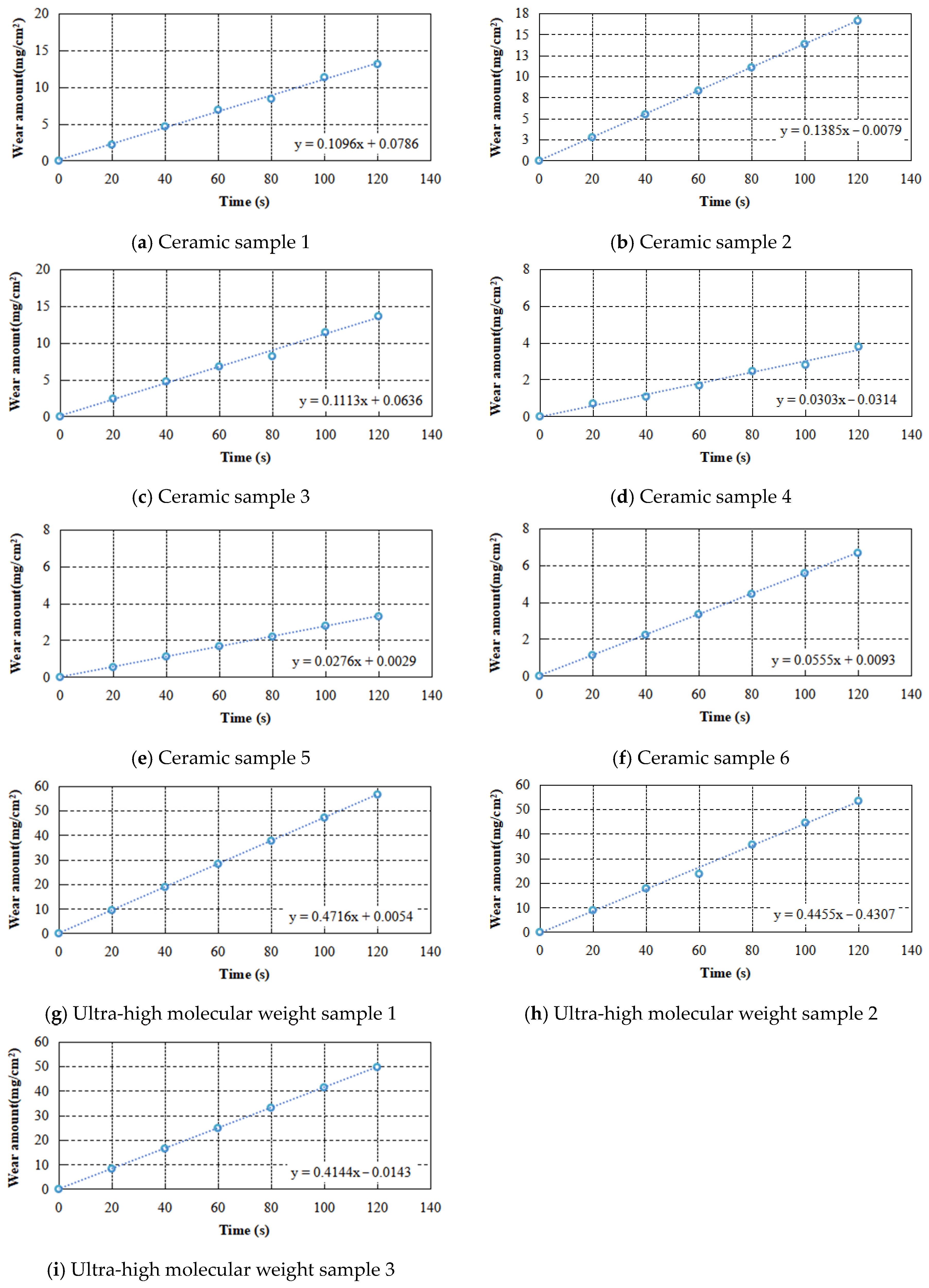
The linear fitting graph of the unit wear of alumina ceramic sample and ultra-high molecular weight sample with time is shown in
Figure 13.
Figure 13 shows that both alumina ceramic sheets and ultra-high molecular wear-resistant sheets exhibit low slope values in their linear fit plots of wear data, indicating excellent surface wear resistance. Notably, the alumina ceramic sheet sample demonstrates an even steeper slope in its wear data analysis, confirming superior wear resistance compared to the ultra-high molecular sample. However, the production cost of ceramic sheets is 3.0 to 3.5 times higher than that of ultra-high molecular wear-resistant materials.
4.3.5. The Numerical Analysis of Wear-Resistant Materials
- (1)
The material model:
Alumina wear-resistant ceramic has an Al2O3 content of 95%, a density of 3.85 g/cm3, a bending strength of 375 MPa, a Rockwell hardness of HRA88, and a high temperature resistance of 1700 °C.
Ultra-high molecular weight wear-resistant material has an average molecular weight of 2.5 million, a density of 0.935 g/cm3, a yield stress of 200 kg/cm2, and a Brinell hardness of 40.
- (2)
The geometric model:
Alumina ceramic sheet dimensions: 100 mm × 100 mm × 5 mm.
Ultra-high molecular wear-resistant sheet: 100 mm × 100 mm × 5 mm.
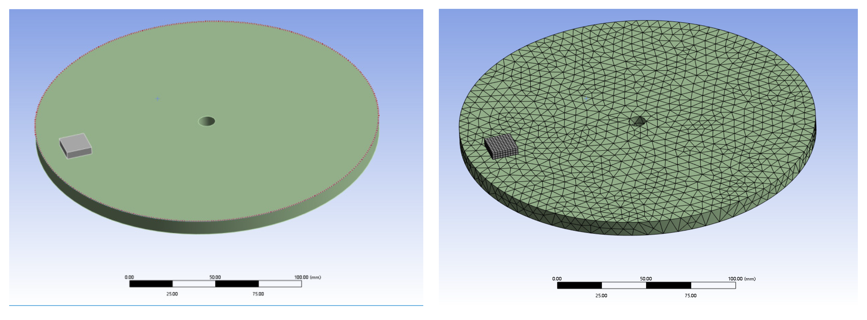
The grinding wheel is a diamond grinding wheel with a thickness of 70 mm, a diameter of 200 mm, a hardness of HB203-HB245, and a rotational speed of 75 r/s. The finite element model is shown in
Figure 14.
- (3)
Simulation conditions:
The alumina ceramic sheet and ultra-high molecular wear-resistant sheet were applied with 0.1372 kN pressure and ground for 2 min.
- (4)
The results of finite element analysis:
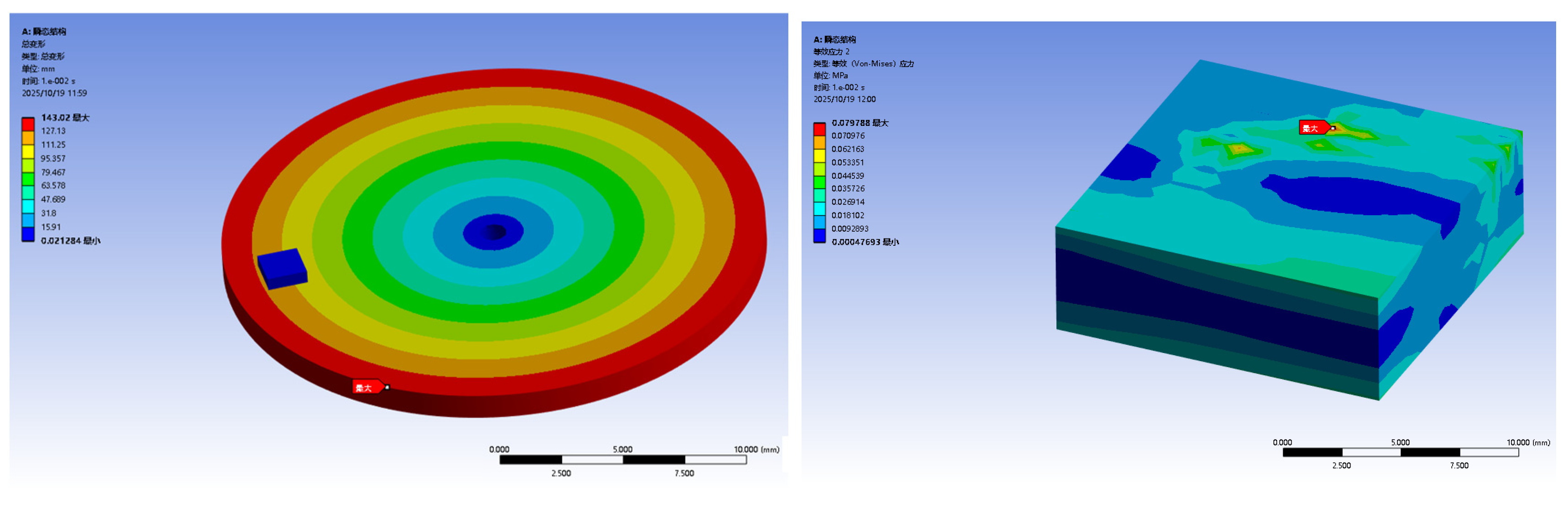
Through finite element simulation, the wear process of alumina ceramics is analyzed, as shown in
Figure 15. The analysis of the simulation data shows that the maximum stress on the alumina ceramic sheet during the wear process is 79.8 kPa, which is far lower than the yield stress of the ceramic sheet, so it shows ultra-high wear resistance.
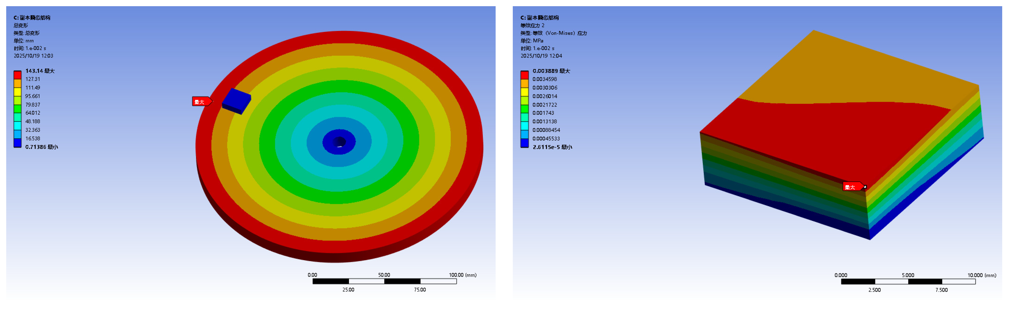
Through the finite element simulation, the wear process of the ultra-high molecular wear-resistant sheet is analyzed, as shown in
Figure 16. The simulation data indicates that the maximum stress on the ultra-high molecular wear-resistant sheet during wear is 3.88 kPa, which is significantly lower than its yield stress, demonstrating exceptional wear resistance.
4.4. Field Test of Wear-Resistant Chute
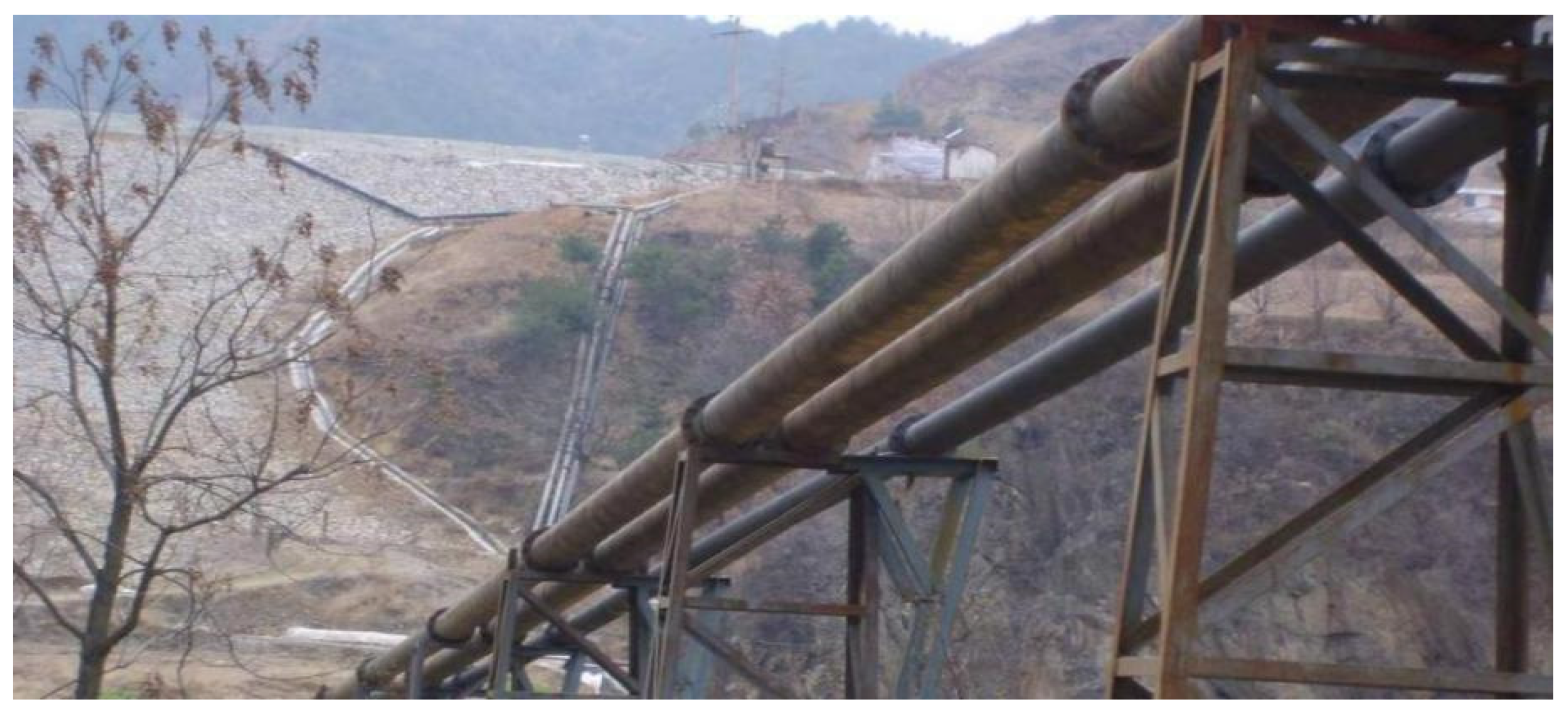
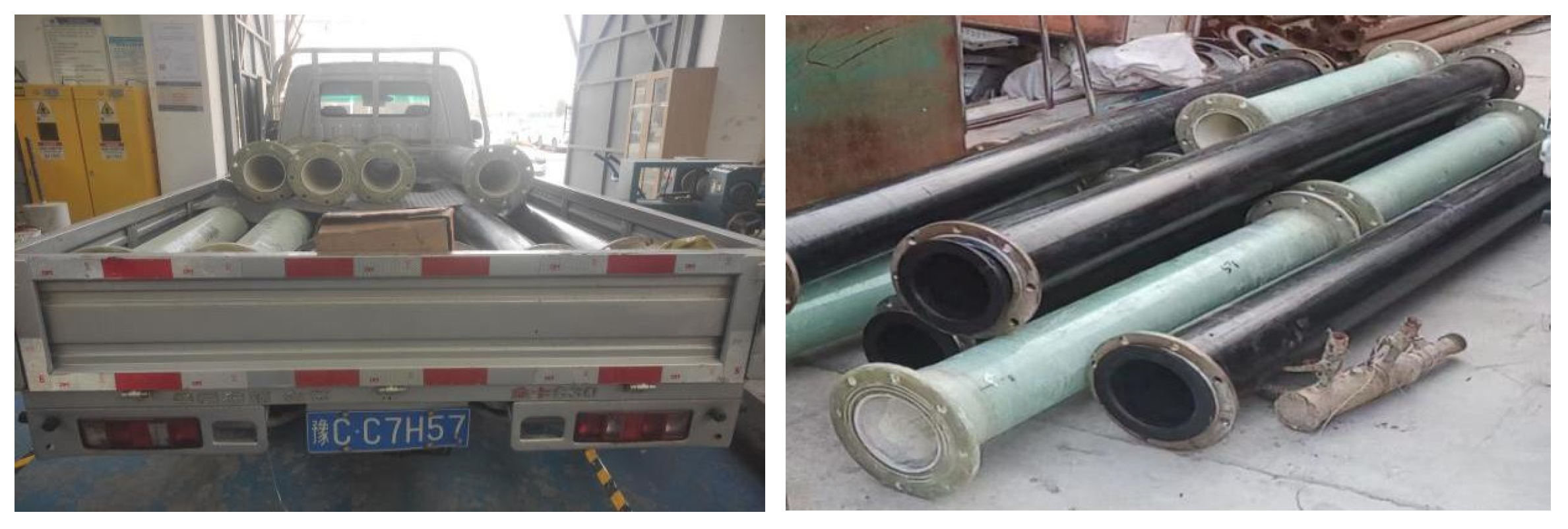
Based on laboratory wear-resistant material testing, both types of wear-resistant pipes were verified to meet on-site casting requirements. For more precise performance evaluation, field tests were conducted. The alumina wear-resistant chute pipe D212 specimen features an inner diameter of 200 mm, outer diameter of 212 mm, 6 mm rubber thickness, and 4–5 mm inner wall lining. Each 1.5 m section weighs 41 kg, with eight sections in total. The ultra-high molecular wear-resistant chute pipe D230 specimen has an inner diameter of 200 mm, outer diameter of 230 mm, 15 mm wall thickness, and 3 m sections, totaling four sections. The finished wear-resistant pipes are shown in
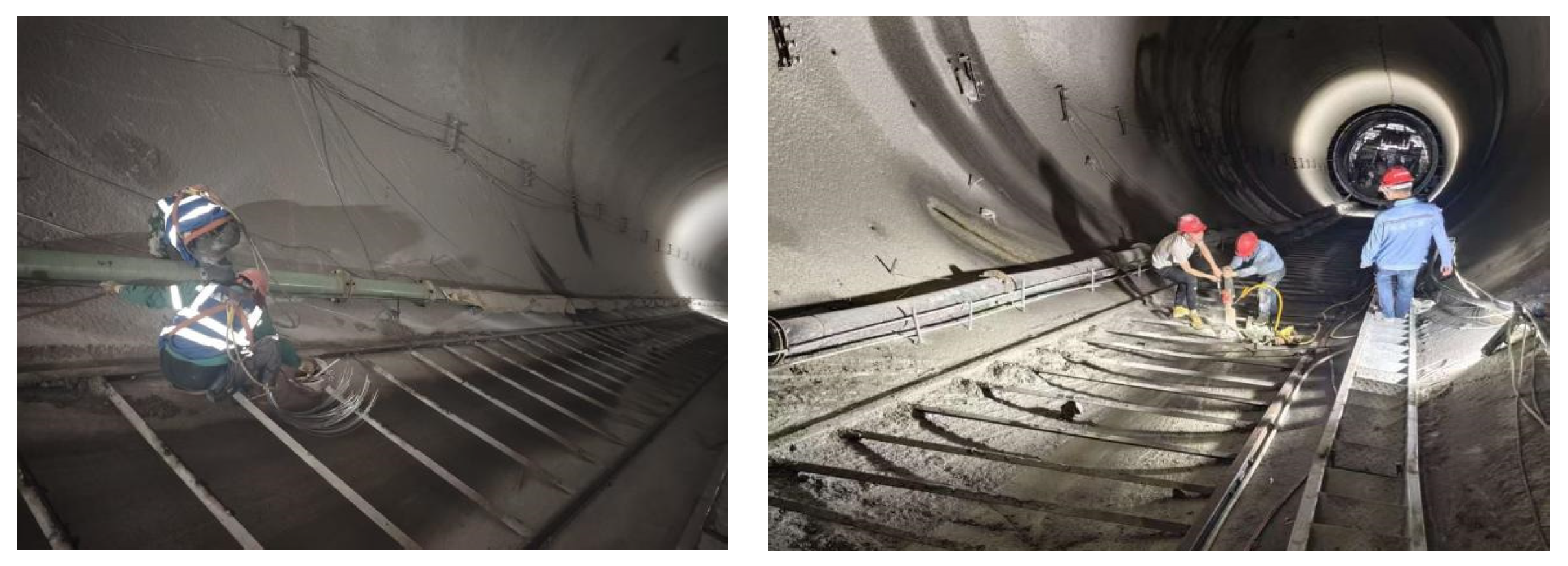
Figure 17. The installation and testing at the water-diversion-inclined shaft tunnel site are shown in
Figure 18.
5. The Economic Analysis of the Abrasion-Resistant Sliding Pipe
Several chute types have been tested both in laboratory and field, all meeting the concrete-pouring requirements. Through direct cost analysis of these chutes, the most suitable option was selected for its construction efficiency and wear resistance. The cost analysis is detailed in
Table 6.
As shown in the table below:
Steel pipe, single section 31.2 kg, convenient for construction, the total weight is 6.24 tons, the relative weight is light, the hardness is medium, the wear resistance is good, but the cost is 250,000 RMB, belonging to medium efficiency.
Alumina ceramic wear-resistant chute, single section 39.5 kg, convenient for construction, total weight 10.95 tons, relatively heavy, best hardness, best wear resistance, but the cost is 614,100 RMB, belonging to medium efficiency.
Ultra-high molecular wear-resistant chute, single section 35.5 kg, convenient construction, total weight 4.75 tons, the lightest weight, good hardness, the best wear resistance, and the cost of 174,200 RMB, belonging to high efficiency.
In the optimization design of the chute, there are two important indicators. The first is the weight of each section, which should not be too heavy. The weight indicator is to meet the requirement that two workers can easily lift it up and install and replace it conveniently on steep slopes. The second indicator is the total cost, which requires controlling the material and production costs of each section. Ceramic tiles with thickness greater than 4 mm have wear resistance that meets engineering requirements. Increasing the thickness would result in a significant increase in weight. By analyzing the changes in key parameters of the chute (such as length and diameter), the increase in weight, material cost, and labor cost is optimized and analyzed, as shown in
Table 7.
Therefore, through the test and field test, concrete chutes are used for pouring concrete inside tunnels or inclined shafts for water diversion. The construction environment is relatively stable and good, and there is no problem regarding material aging. In addition, concrete chutes belong to temporary construction technology. Typically, the concrete pouring volume for a 400 m tunnel or inclined shaft for water diversion is 8000 cubic meters, and the continuous pouring time is 6 months. Durability issues can be ignored while meeting wear-resistance requirements. By observing the situation at the construction site, both schemes meet the requirements for wear resistance and there is no occurrence of impact damage. The key indicators considered are the lightest weight and ease of steep slope construction and replacement. It is known that ultra-high molecular wear-resistant pipe is recommended to be used in the long-distance concrete slip on the large slope, which is not only light and high-strength, but it also has the best wear-resistance, its cost is lower, its construction is quick, and its economic effect is better.
6. Summary
Through theoretical analysis, the experimental test, finite element simulation and the field test, the following conclusions were obtained:
Through the theoretical analysis, the mix proportion and additive of concrete pumping were determined to meet the requirements of segregation-free concrete in the concrete chute for long distance and high drop.
Alumina ceramics and ultra-high molecular wear-resistant materials were selected as the wear-resistant layer of the concrete chute. Through the grinding wheel wear test and finite element numerical simulation, the wear-resistant performance of the two materials could meet the construction requirements of the concrete chute.
Custom-made eight-section fiberglass-reinforced plastic (FRP) chute lined with alumina ceramic sheets and four-section ultra-high molecular wear-resistant chute were tested in field concrete discharge. After prolonged observation and application, practical results confirmed that both chute solutions were viable.
The overall economic benefits were evaluated through comprehensive factors, including pipeline cost, construction duration, labor expenses, and replacement costs. Ultra-high molecular wear-resistant concrete pipelines, with their exceptional wear resistance and cost-effectiveness, offer significant advantages in concrete pipeline applications. By reducing lifecycle costs through lightweight design and low maintenance requirements, these pipelines demonstrate dual strengths in performance and economy, making them irreplaceable in the concrete pipeline industry.
Author Contributions
Conceptualization, Z.Z.; methodology, Z.Z. and Y.L.; software, P.H.; validation, F.L., Z.W. and L.X.; formal analysis, Z.Z., P.H. and Y.L.; investigation, Z.Z., Y.L., E.G. and H.C.; resources, Z.W. and L.X.; data curation, E.G. and H.C.; writing—original draft preparation, Z.Z. and P.H.; writing—review and editing, Z.Z., Y.L. and F.L.; funding acquisition, P.H. and E.G. All authors have read and agreed to the published version of the manuscript.
Funding
This work was supported by the Key Scientific Research Project of Colleges and Universities in Henan Province (Grant No. 18A560010). The authors are grateful for the funds provided by Sinohydro Bureau 7 Co., Ltd. (Grant No. Sinohydro 2022-803-54-21).
Institutional Review Board Statement
Not applicable.
Informed Consent Statement
Not applicable.
Data Availability Statement
The data presented in this study are available on request from the corresponding author due to the limitations of the school enterprise cooperation project contract.
Acknowledgments
We are thankful to the reviewers for their thoughtful and constructive critiques, which have helped to enhance the overall quality of the paper.
Conflicts of Interest
The authors declare that this study received funding from Sinohydro Bureau 7 Co., Ltd. The funder was not involved in the study design, collection, analysis, interpretation of data, the writing of this article or the decision to submit it for publication. Authors Zhaogao Zeng, Pengfei Hu, Yunjin Li, Feng Luo, Zhiguo Wang and Liqin Xun were employed by the company Sinohydro Bureau 7 Co., Ltd. The remaining authors declare that the research was conducted in the absence of any commercial or financial relationships that could be construed as a potential conflict of interest.
References
- He, H.Y.; Fang, T.C.; Zuo, J.Q.; Wu, L.D.; Ma, W. Design and research of high fluidity concrete ultra-deep intelligent pouring equipment. Anhui Archit. 2025, 32, 13–15. [Google Scholar] [CrossRef]
- Tang, J.C. Research on self-compacting concrete pouring technology based on shield construction. Constr. Technol. Dev. 2025, 52, 39–42. [Google Scholar] [CrossRef]
- Peng, Z.H.; Xu, H.Y.; Xiao, J.; Li, J.Q.; Li, N. Experimental study on concrete pipeline transportation in low pressure and large height difference environment. Constr. Technol. (Chin. Engl.) 2025, 54, 8–13. [Google Scholar]
- Wang, X.Y. Analysis on the construction technology of large volume concrete pouring for foundation slab. Build. Sci. Technol. 2024, 8, 88–92. [Google Scholar]
- Wang, H. Construction of the full pipe chute conveying technology. Jushe 2023, 36, 42–44+55. [Google Scholar]
- Liao, G.L. Construction and quality control of deep shaft in pumped storage power station. Guangdong Water Resour. Hydropower 2023, 10, 88–93. [Google Scholar]
- Wang, Q.; Chen, Q. Research on the construction technology of continuous concrete pouring for down feeding in deep shafts. Jiangxi Build. Mater. 2023, 04, 178–179+184. [Google Scholar]
- Fan, C.X.; Song, M.L. Research on construction technology and mix ratio of ultra-deep shaft lining concrete. Hydropower New Energy 2023, 37, 14–17. [Google Scholar] [CrossRef]
- Zhou, S.H. Construction technology of large volume concrete pouring in super large deep foundation pit with sliding pipe. Jiangxi Build. Mater. 2022, 07, 213–215. [Google Scholar]
- Zhang, W.G.; Pei, J.C.; Qin, F.; Xu, M.Z.; Wang, Y. A brief analysis of the application of pipe-laid construction technology in large volume concrete pouring. Sichuan Build. Mater. 2022, 48, 132+138. [Google Scholar]
- Shi, A.J.; Wang, Y.J.; Yao, C.K.; Xie, X.M.; Wu, Y.L.; Cai, Y.X. Construction technology of self-compacting concrete lining in water shield tunnel. People’s Pearl River 2022, 43, 36–41+55. [Google Scholar]
- Liu, X.; Li, Y.; Li, K.J.; Yan, M. Application of rotating block assembly method for large volume concrete chute construction. Constr. Technol. Dev. 2021, 48, 103–104. [Google Scholar]
- Zhang, J.T. Research on the construction technology and key points control of concrete in vertical conveying tunnel of high drop shaft. Shanxi Water Conserv. Sci. Technol. 2021, 04, 32–34. [Google Scholar]
- Yu, H.S. Research on the construction technology of large volume floor concrete in deep foundation pit based on rapid pouring of chute pipe. Ph.D. Thesis, Xi’an University of Architecture and Technology, Xi’an, China, 2021. [Google Scholar] [CrossRef]
- Zhao, R.J.; Kong, L.; Xue, L.; Zhao, Z.Y.; Shao, F.X. Concrete free pumping non-interruption full range slip pipe pouring technology. Anhui Archit. 2020, 27, 71+82. [Google Scholar] [CrossRef]
- Lai, X.W. Research on the Safety Transportation and Anti-Segregation of Concrete in Ultra-High Drop Depth Shaft. Ph.D. Thesis, South China University of Technology, Guangzhou, China, 2020. [Google Scholar] [CrossRef]
- Wang, G.W. Research on Rapid Construction Technology of Self-Compacting Concrete and Lining for High Altitude Steep and Deep Inclined Wells. Ph.D. Thesis, Xinjiang Agricultural University, Urumqi, China, 2014. [Google Scholar]
- Liu, S.H. Application of High Content Grade II Fly Ash Concrete in Deep Inclined Shaft Lining. Ph.D. Thesis, Xinjiang Agricultural University, Urumqi, China, 2014. [Google Scholar]
- Jiang, Y.Y.; Cheng, X.R. Construction Technology of Steel Pipe Installation and Concrete for Extra-long Inclined Shaft of Pumped Storage Power Station. Electr. Power Surv. Des. 2022, 09, 64–67+88. [Google Scholar] [CrossRef]
- Sun, J.L.; Yang, H.M.; Zhang, Y.F. Research on Transportation Technology of Concrete Chute in Gentle Slope and Super-long Inclined Shaft. Sichuan Hydro Power 2019, 38, 97–99+102. [Google Scholar]
- Zeng, J.J.; Zeng, W.B.; Zhuge, Y.; Zhou, J.-K.; Quach, W.-M.; Feng, R.; Ye, T.H. Behavior and modeling of FRP grid-reinforced ultra-high-performance concrete under uniaxial tension. Struct. Concr. 2024, 2, 1185–1207. [Google Scholar] [CrossRef]
- Liao, J.J.; Lin, X.C.; Zhu, D.H.; Zheng, Y.; Zeng, J.-J.; Ma, C.-L.; Zhao, H.-C. Behavior of FRP grid-reinforced ultra-high performance concrete (UHPC) pipes under lateral compression. Case Stud. Constr. Mater. 2023, 19, e02189. [Google Scholar] [CrossRef]
- ASTM D1505-25; Standard Test Method for Density of Plastics by the Density-Gradient Technique. ASTM Committee: West Conshohocken, PA, USA, 2025.
- GB/T 1841-1980; Test Method for the Viscosity of the Dilute Solution of Polyolefine Resin. Ministry of Chemical Industry of the PRC: Beijing, China, 1980.
- ASTM D638-22; Standard Test Method for Tensile Properties of Plastics. ASTM Committee: West Conshohocken, PA, USA, 2022.
- ASTM D256-24; Standard Test Methods for Determining the Izod Pendulum Impact Resistance of Plastics. ASTM Committee: West Conshohocken, PA, USA, 2024.
- ASTM D2240-15; Standard Test Method for Rubber Property-Durometer Hardness. ASTM Committee: West Conshohocken, PA, USA, 2015.
- ASTM D2117-82; Standard Test Method for Melting Point of Semicrystalline Polymers by the Hot Stage Microscopy Method. ASTM Committee: West Conshohocken, PA, USA, 1988.
- ASTM D1525-25; Standard Test Method for Vicat Softening Temperature of Plastics. ASTM Committee: West Conshohocken, PA, USA, 2025.
- ASTM D648-18; Standard Test Method for Deflection Temperature of Plastics Under Flexural Load in the Edgewise Position. ASTM Committee: West Conshohocken, PA, USA, 2018.
- GB/T 12988-2009; Test Method for Abrasion Resistance of Inorganic Paving Materials. National Standardization Administration: Beijing, China, 2009.
Figure 1.
Layout of concrete chute pipe.
Figure 1.
Layout of concrete chute pipe.
Figure 2.
Engineering application of alumina wear-resistant sheet.
Figure 2.
Engineering application of alumina wear-resistant sheet.
Figure 3.
Alumina wear-resistant chute pipe.
Figure 3.
Alumina wear-resistant chute pipe.
Figure 4.
Finished alumina wear-resistant chute pipe.
Figure 4.
Finished alumina wear-resistant chute pipe.
Figure 5.
Alumina wear-resistant chute finished product.
Figure 5.
Alumina wear-resistant chute finished product.
Figure 6.
High-head double-line tailings conveying project of a mineral processing plant.
Figure 6.
High-head double-line tailings conveying project of a mineral processing plant.
Figure 7.
Ultra-high molecular wear-resistant chute.
Figure 7.
Ultra-high molecular wear-resistant chute.
Figure 8.
Ultra-high polymer wear-resistant chute joint adopts flange connection.
Figure 8.
Ultra-high polymer wear-resistant chute joint adopts flange connection.
Figure 9.
Schematic diagram of test member dimensions. Green represents alumina ceramic patch.
Figure 9.
Schematic diagram of test member dimensions. Green represents alumina ceramic patch.
Figure 10.
Schematic diagram of the grinding wheel wear test apparatus.
Figure 10.
Schematic diagram of the grinding wheel wear test apparatus.
Figure 11.
Wear appearance of alumina ceramic sheet. (a) Wear condition of No. 3 thick porcelain tile. (b) The upper image depicts the wear condition of thick ceramic tiles, while the lower image illustrates the wear condition of thin ceramic tiles.
Figure 11.
Wear appearance of alumina ceramic sheet. (a) Wear condition of No. 3 thick porcelain tile. (b) The upper image depicts the wear condition of thick ceramic tiles, while the lower image illustrates the wear condition of thin ceramic tiles.
Figure 12.
Wear appearance of ultra-high molecular sheet.
Figure 12.
Wear appearance of ultra-high molecular sheet.
Figure 13.
Variation in wear per unit area over time.
Figure 13.
Variation in wear per unit area over time.
Figure 14.
Finite element model of wear test.
Figure 14.
Finite element model of wear test.
Figure 15.
Wear results of alumina ceramics. (A 瞬态结构—A Transient structure; 总变形—Total deformation; 类型: 总变形—Type: Total deformation; 单位: mm—Unit: mm; 时间:—Time:; 最大—Maximum; 最小—Minimum); 等效应力2—Equivalent stress 2; 类型: 等效(Von Mises) 应力—Type: Equivalent (Von Mises) stress; 1e-0.02—1 × 10−0.02.
Figure 15.
Wear results of alumina ceramics. (A 瞬态结构—A Transient structure; 总变形—Total deformation; 类型: 总变形—Type: Total deformation; 单位: mm—Unit: mm; 时间:—Time:; 最大—Maximum; 最小—Minimum); 等效应力2—Equivalent stress 2; 类型: 等效(Von Mises) 应力—Type: Equivalent (Von Mises) stress; 1e-0.02—1 × 10−0.02.
Figure 16.
Wear results of ultra-high molecular wear-resistant sheet.
Figure 16.
Wear results of ultra-high molecular wear-resistant sheet.
Figure 17.
The finished product of the wear-resistant tube.
Figure 17.
The finished product of the wear-resistant tube.
Figure 18.
On-site installation of ceramic and ultra-high molecular wear-resistant chute pipes.
Figure 18.
On-site installation of ceramic and ultra-high molecular wear-resistant chute pipes.
Table 1.
Threshold values of anti-segregation parameters.
Table 1.
Threshold values of anti-segregation parameters.
| Concrete Type | Measured Yield Stress τ0 (Pa) | Measured Plastic Viscosity η (Pa·s) | Core Requirements |
|---|
Self-Compacting
concrete | 20~50 | 100~300 | Vibration, flow, and separation resistance should not be considered |
| Pumping Concrete | 30~70 | 150~400 | Resisting pumping shear and vertical casting
segregation |
Table 2.
SF1, self-compacting concrete.
Table 2.
SF1, self-compacting concrete.
| Material | Specifications | Quality (kg) | Scale |
|---|
| Water–cement ratio | | | 0.47 |
| Slumps | 550–650 | | |
| Sand–coarse aggregate ratio | | | 50% |
| Cement | PO425 | 290 | 1 |
| Sand | Artificial sand (medium sand) | 825 | 2.85 |
| Cobblestone | Gravel (5–20 mm) | 844 | 2.91 |
| Water | PH = 7.0 | 182 | 0.628 |
| Fly ash | Class F, level II | 97 | 25% |
| Water reducer | VK.CS retarder | 3.096 | 0.80% |
| Air-entraining agent | VK.AE liquid state | 0.3096 | 8/m3 |
Table 3.
Performance parameters of nano alumina wear-resistant ceramics.
Table 3.
Performance parameters of nano alumina wear-resistant ceramics.
| Al2O3 Content | Compression Strength | Rockwell Hardness |
|---|
| 95% | 850 MPa | HRA88 |
| Density | Bending Strength | Temperature Resistance |
| 3.85 g/cm3 | 375 MPa | −50~1700 °C |
Table 4.
Performance parameters of ultra-high molecular weight wear-resistant materials.
Table 4.
Performance parameters of ultra-high molecular weight wear-resistant materials.
| Project | Unit | Experimental Methodology | Test Value |
|---|
| Density | g/cm3 | ASTM D1505 [23] | 0.935 |
| Average molecular weight | GB/T1841 [24] | Viscosity method | 2.5 million |
| Yield point stress | kg/cm2 | ASTM D638 [25] | 220 |
| Tensile strength | kg/cm2 | ASTM D638 | 400 |
| Elongation at break | % | ASTM D638 | 350 |
| Impact strength (no notch) | kg·cm/cm | ASTM D256 [26] | Do not destroy |
| Impact strength (notch) | kg·cm/cm | ASTM D256 | 110 |
| Brinell hardness | D | ASTM D2240 [27] | 40 |
| Coefficient of kinetic friction | kg/cm2·m/s | Mitsui Chemical | 0.2 |
| wear rate (sand grinding method) | mg | Mitsui Chemical | 20 |
| Melting point | °C | ASTM D2117 [28] | 136 |
| Vickers softening point | °C | ASTM D1525 [29] | 134 |
| Distortion temperature | °C | ASTM D648 [30] | 85 |
| Thermal conductivity | 10-cal/cm·s·°C | ASTM D2177 | 8.5 |
Table 5.
Variation in wear rate per unit area over time (mg/cm2).
Table 5.
Variation in wear rate per unit area over time (mg/cm2).
| Time (s) | Ceramic
Sample 1 | Ceramic
Sample 2 | Ceramic
Sample 3 | Ceramic
Sample 4 | Ceramic
Sample 5 | Ceramic
Sample 6 |
|---|
| 0 | 0.00 | 0.00 | 0.00 | 0.00 | 0.00 | 0.00 |
| 20 | 2.18 | 2.77 | 2.41 | 0.70 | 0.54 | 1.13 |
| 40 | 4.66 | 5.50 | 4.76 | 1.07 | 1.12 | 2.23 |
| 60 | 6.91 | 8.31 | 6.79 | 1.68 | 1.68 | 3.35 |
| 80 | 8.40 | 11.07 | 8.18 | 2.46 | 2.20 | 4.44 |
| 100 | 11.33 | 13.84 | 11.44 | 2.80 | 2.79 | 5.57 |
| 120 | 13.12 | 16.61 | 13.62 | 3.79 | 3.30 | 6.67 |
| Time (s) | Ultra-High Molecular
Weight Sample 1 | Ultra-High Molecular
Weight Sample 2 | Ultra-High Molecular
Weight Sample 3 |
| 0 | 0.00 | 0.00 | 0.00 |
| 20 | 9.44 | 8.91 | 8.29 |
| 40 | 18.88 | 17.80 | 16.50 |
| 60 | 28.30 | 23.73 | 24.86 |
| 80 | 37.73 | 35.64 | 33.15 |
| 100 | 47.17 | 44.56 | 41.42 |
| 120 | 56.60 | 53.44 | 49.71 |
Table 6.
Cost analysis of pipeline.
Table 6.
Cost analysis of pipeline.
| Name | Specifications | Section Length (m) | Weight per Meter
(kg) | Weight per Unit (kg) | Unit Price per Section (RMB) | Pitch Number (n) | Total Weight
(t) | Total Cost
(Thousand) |
|---|
| Steel chute | Φ470 × 2 | 2 | 15.6 | 31.2 | 1250 | 200 | 6.24 | 250.0 |
| Alumina ceramic wear-resistant chute | Φ212 × (5) | 1.5 | 18 | 41.0 | 2300 | 267 | 10.95 | 614.1 |
| Alumina ceramic wear-resistant chute | Φ212 × (4) | 1.5 | 17 | 39.5 | 2100 | 267 | 10.55 | 560.7 |
| Ultra-high molecular wear-resistant chute | Φ230 × 15 | 3 | 10 | 35.5 | 1300 | 134 | 4.75 | 174.2 |
Table 7.
Parameter analysis of pipeline.
Table 7.
Parameter analysis of pipeline.
| Name | Specifications | Section
Length
(m) | Weight
per Unit
(kg) | Every 1000 mm Increase in Length | Every 50 mm Increase in Diameter |
|---|
Increase
Weight
(kg) | Increase Weight
Ratio | Labor Cost
Ratio | Increase
Weight (kg) | Increase
Weight
Ratio | Labor
Cost
Ratio |
|---|
| Steel chute | Φ470 × 2 | 2.0 | 31.2 | 15.6 | 50.0% | 5.0% | 3.3 | 10.6% | 5.0% |
| Alumina ceramic wear-resistant chute | Φ212 × (5) | 1.5 | 41.0 | 11.3 | 27.6% | 50.0% | 8.6 | 21.0% | 30.0% |
| Alumina ceramic wear-resistant chute | Φ212 × (4) | 1.5 | 39.5 | 11.3 | 28.6% | 50.0% | 8.3 | 21.0% | 30.0% |
| Ultra-high molecular wear-resistant chute | Φ230 × 15 | 3.0 | 35.5 | 9.8 | 27.6% | 5.0% | 6.9 | 19.4% | 5.0% |
| Disclaimer/Publisher’s Note: The statements, opinions and data contained in all publications are solely those of the individual author(s) and contributor(s) and not of MDPI and/or the editor(s). MDPI and/or the editor(s) disclaim responsibility for any injury to people or property resulting from any ideas, methods, instructions or products referred to in the content. |