1. Introduction
Fatigue cracking in steel structures poses a significant risk to their safety and durability. Understanding the causes and prevention of such failures is essential for reliable structural design [
1]. Fatigue is a critical failure mechanism in structural components under cyclic loading, responsible for up to 90% of metallic failures [
2]. Fatigue crack initiation begins with plastic strain accumulation, followed by crack growth driven primarily by tensile stress [
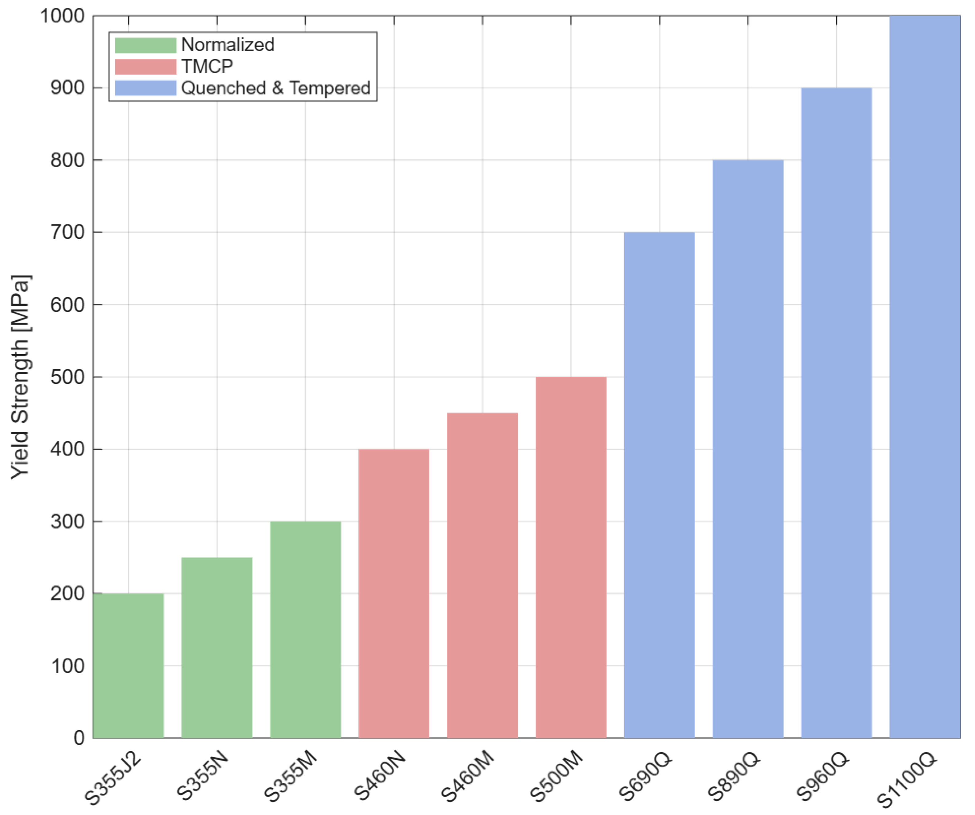
3]. The material properties depend on the alloying elements and the steel production process. Steels are classified according to their yield strengths as conventional strength steels (CSS) S275, S355, S460, and high-strength steels (HSS), such as S690, S700, and S960, and based on the delivery conditions according to European standards, as depicted in
Figure 1. Steels S690 and S700 are low-alloy HSS widely used in demanding applications, such as offshore structures, construction, and mining equipment. Their popularity comes from their high-strength combined with excellent impact toughness, especially at low temperatures. However, there is a trade-off between achieving high-strength and addressing challenges during fabrication, particularly welding. The literature reports on issues, such as the development of residual stresses, complications related to large plate thickness, and increased costs, compared to CSS [
4,
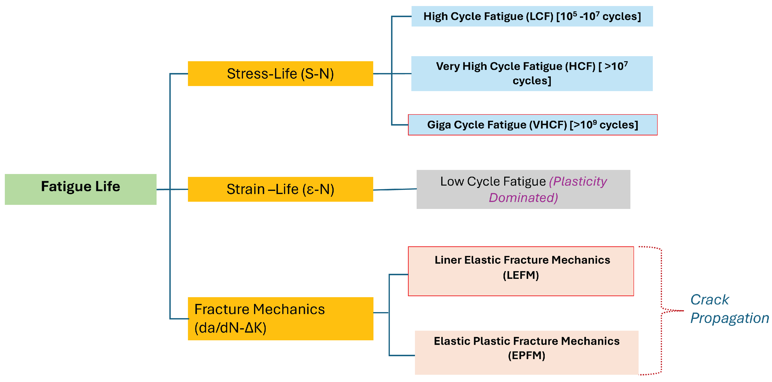
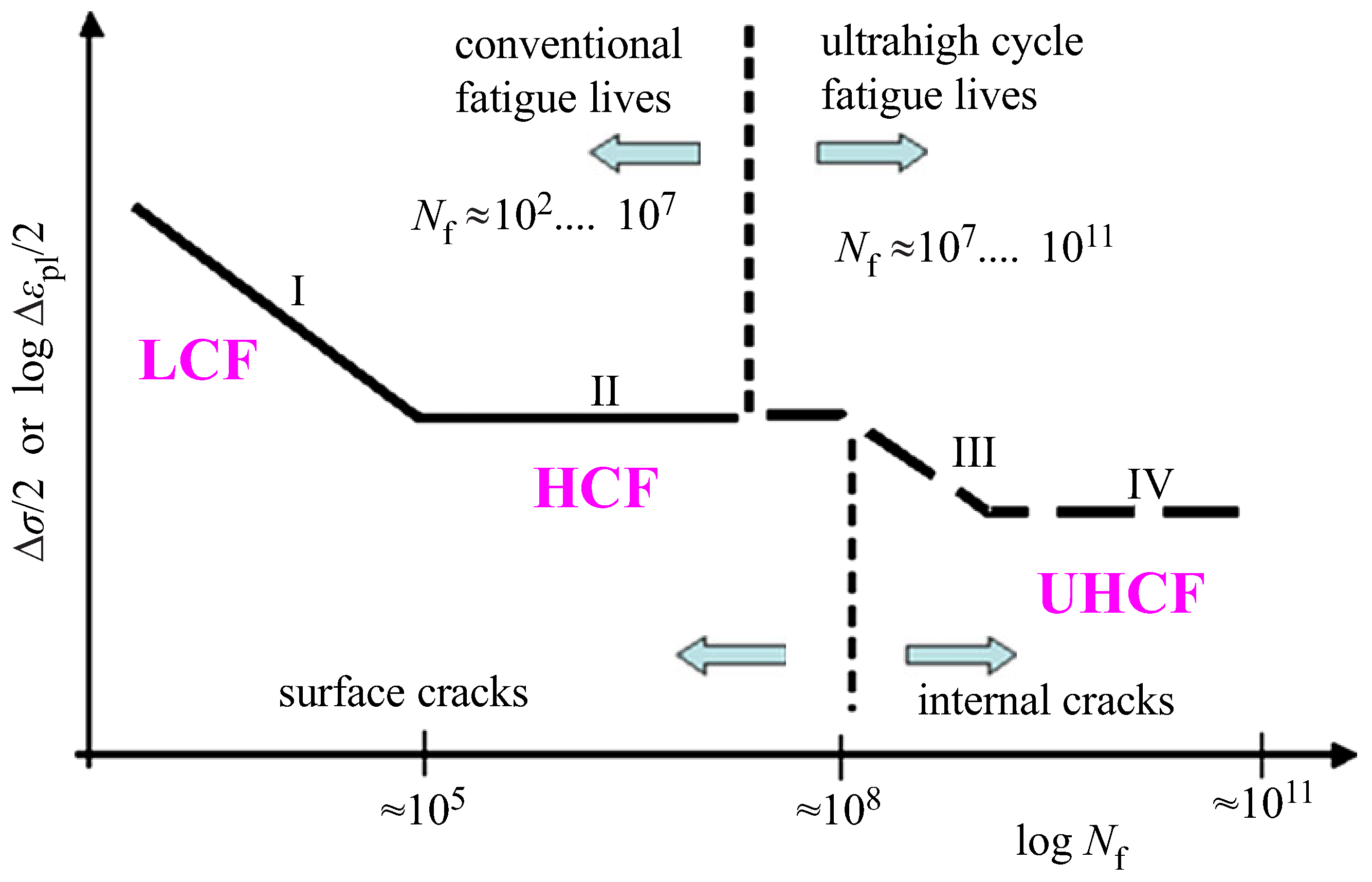
5]. Fatigue life prediction is typically divided in three groups, as shown in
Figure 2.
Stress–Life (S–N) fatigue regimes are classified based on the cycles to failure as low-cycle fatigue (LCF) equal to
cycles, high-cycle fatigue (HCF), ranging between
–
cycles, and VHCF (>
cycles). The gigacycle region is greater than
cycles with HSS (
MPa) showing VHCF failure beyond
cycles [
6,
7]. The gigacycle region is greater than
cycles with HSS (
MPa), showing VHCF failure beyond
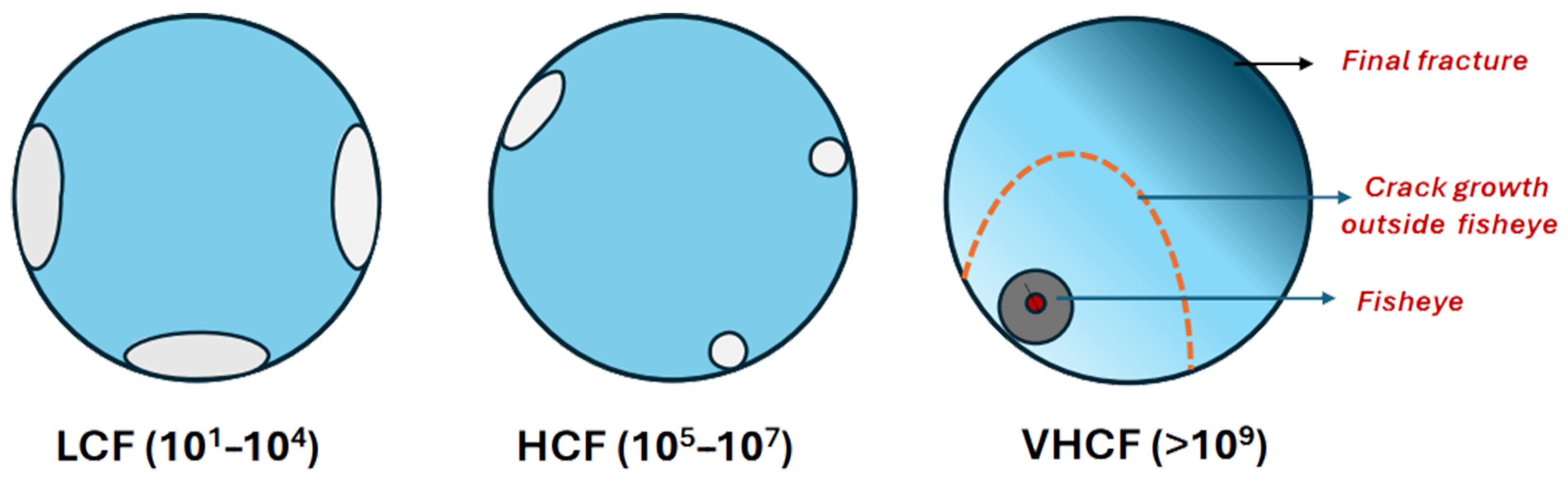
cycles as in
Figure 3. The study of VHCF in steels has gained significant attention due to the increasing demand for structural components that operate reliably over billions of loading cycles [
8,
9,
10]. Applications, such as railway axles, wind turbine shafts, offshore structures, and automotive transmission systems, often experience cyclic loading far beyond the conventional HCF range of
cycles [
11]. In the VHCF regime, the classical assumption of a horizontal fatigue limit is no longer valid, as experimental evidence shows a continued decline in fatigue strength with increasing cycles [
8].
For HSS, fatigue failure in this domain is predominantly driven by internal crack initiation at non-metallic inclusions, producing characteristic fisheye and granular bright facet (GBF) fracture morphologies [
13,
14]. These mechanisms differ markedly from the surface-driven crack initiation observed in the LCF and HCF regimes, as displayed in
Figure 4, and their progression can consume a major portion of the total fatigue life [
15]. Advancements in ultrasonic fatigue testing (UFT), which typically operate at frequencies between 20 and 30 kHz, have made it possible to quickly gather fatigue data for over a billion cycles. This progress allows for effective study of VHCF behaviour in steels, which is crucial for ensuring the reliability and safety of critical components that may fail under low stress levels over long service times.
After crack initiation, fatigue crack propagation becomes the primary stage of material failure under cyclic loading. In this stage, the crack grows incrementally with each load cycle, gradually reducing the remaining fatigue life. The crack growth rate is mainly governed by the stress intensity factor range (
K) at the crack tip. Environmental factors, such as temperature [
16], corrosion [
17], and humidity [
18,
19], can influence the propagation rate. Surface features like striations often indicate the incremental crack advance per cycle. Fatigue crack propagation is usually divided into a stable growth region and an unstable region, leading to final fracture. The stable growth phase often represents most of the components’ fatigue life. In 1961, Paris [
20] proposed a fatigue crack growth model establishing a relationship between the stress intensity factor (SIF) and the crack growth rate, which has since been extensively applied to predict fatigue behaviour in various engineering materials.
This review examines the VHCF behaviour of steels, from CSS to HSS, focusing on factors affecting fatigue life, including microstructure, loading, and environmental effects. It covers both crack initiation and fracture mechanics-based fatigue crack propagation (FCGR). Practical aspects of UFT, such as sample design, challenges in UFT and geometry constraints, are also discussed. By synthesising prior studies, the review identifies trends in VHCF behaviour, clarifies key governing factors, and frames these insights within a total fatigue life perspective.
Despite these advances, challenges include that comparative analyses across steel classes under consistent testing protocols are limited, and practical issues, such as frequency effect, heating issues, and UFT standardization, complicate experimental interpretation. This review addresses these gaps by (i) critically evaluating VHCF research in HSS and CSS; (ii) summarising key factors affecting crack initiation and propagation; (iii) the influence of working environment; and (iv) integrating findings within a total fatigue life framework, providing a foundation for future experimental and modelling studies.
2. Fatigue Crack Initiation
Fatigue failure in steels progresses through a series of stages, beginning with the formation of microcracks at material imperfections or localised microstructural irregularities. In the VHCF domain, where the cycle count surpasses
, crack initiation dominates the overall fatigue lifespan because cracks tend to originate from subsurface inclusions or persistent slip bands, often without noticeable macroscopic plastic strain [
21]. Consequently, pinpointing the mechanisms and sites of crack initiation is essential for reliable fatigue life forecasting and for guiding material design strategies.
To explore these initiation phenomena in depth, researchers use UFT testing. This technique extends experimental fatigue evaluation into the VHCF range, allowing direct observation of nucleation sites, measurement of initiation stress thresholds, and analysis of how specific microstructural characteristics affect fatigue resistance. By integrating crack-initiation insights obtained from VHCF tests into comprehensive fatigue-life models, engineers can devise HSS alloys with superior durability under extreme cyclic loading conditions.
Ultrasonic Fatigue Testing
A typical UFT machine can produce fatigue data at frequencies around 20 kHz, enabling testing speeds up to 1000 times faster than traditional methods. This allows for cost-effective evaluation in the VHCF regime exceeding
cycles. The test times are listed in
Table 1. The advantages of the UFT machine include the ability to achieve targeted testing cycles quickly. Achieving
cycles will take 3 years when testing at 100 Hz, but using the UFT machine it could be achieved in seven days [
8].
Rotating bending fatigue machine induces cyclic bending loads, which can modify alloy failure mechanisms in the VHCF regime [
22]. Servo-hydraulic systems can generate random waveforms [
2], but each cycle requires a hydraulic pressure, causing high energy consumption and leading to a high rise in temperature in the test system, thereby limiting the use of conventional machines in the VHCF regimes. UFT is ideally suited for evaluating the failure properties and probing the existence of the fatigue threshold under sinusoidal loading because its very high frequency (20 kHz) produces internal fracture surface rapidly, allowing clear observation of inclusions at crack origins and a detailed size distribution of those inclusions [
7,
23]. The main drawbacks stem from the high loading frequency, which can cause a shift in the effective stress state, significant heat generation, and strain rate effects that reduce fatigue resistance as temperature rises [
24]. To limit temperature rise, tests are usually performed in stress blocks separated by cooling intervals, but UFT remains constrained by specimen size and geometry and relies on displacement control rather than true stress or strain control [
23]. The “frequency effect” is still debated: some studies report material-dependent modifications of the stress field, while others find negligible differences for gigacycle fatigue dominated by internal cracks. Overall, when thermal and frequency artefacts are properly managed, UFT provides an efficient tool for investigating gigacycle VHCF fatigue driven by internal fracture mechanisms. The factors influencing the test results at VHCF are discussed in detail in the later section.
Ultrasonic fatigue testers, whether supplied by commercial vendors as listed in
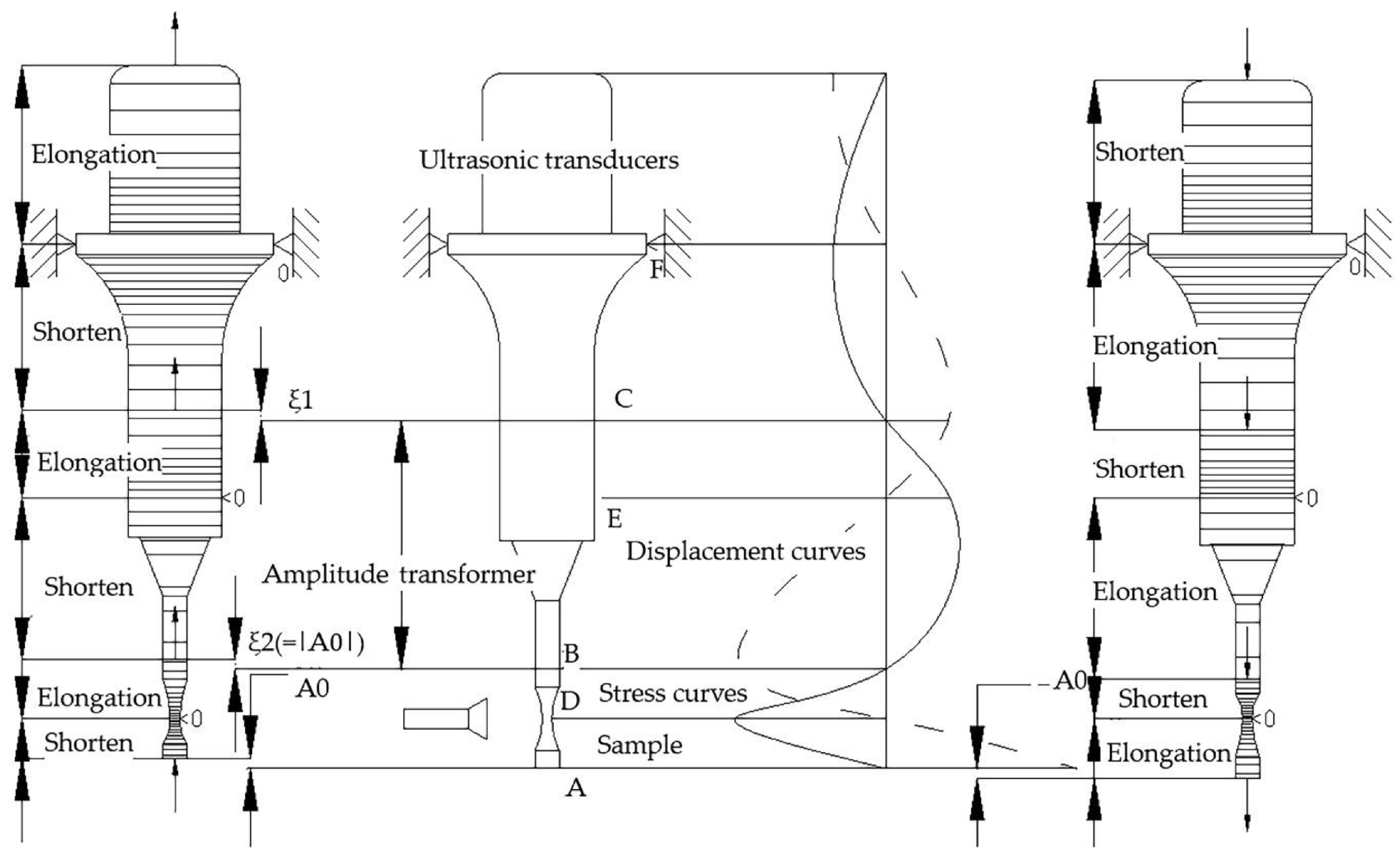
Table 2 or built-in research labs, share a single underlying mechanical principle for generating the cyclic load. The difference between the machines is the levels of process control, the precision they can achieve, and the range of testing applications they support. Despite these variations, the core mechanism that drives the load train remains fundamentally the same. The main components of the UFT machine are shown in
Figure 5. Along the vibration axis, the standing wave pattern yields three stress nodes (A, B, and C), where stress is zero, and particle displacement is maximal, and three displacement nodes (D, E, and F), where displacement is zero and stress reaches its peak (displacement leads stress by ≈90°).
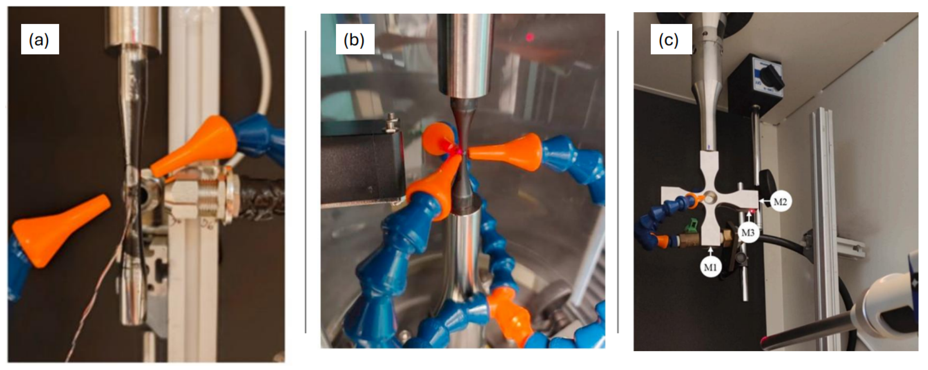
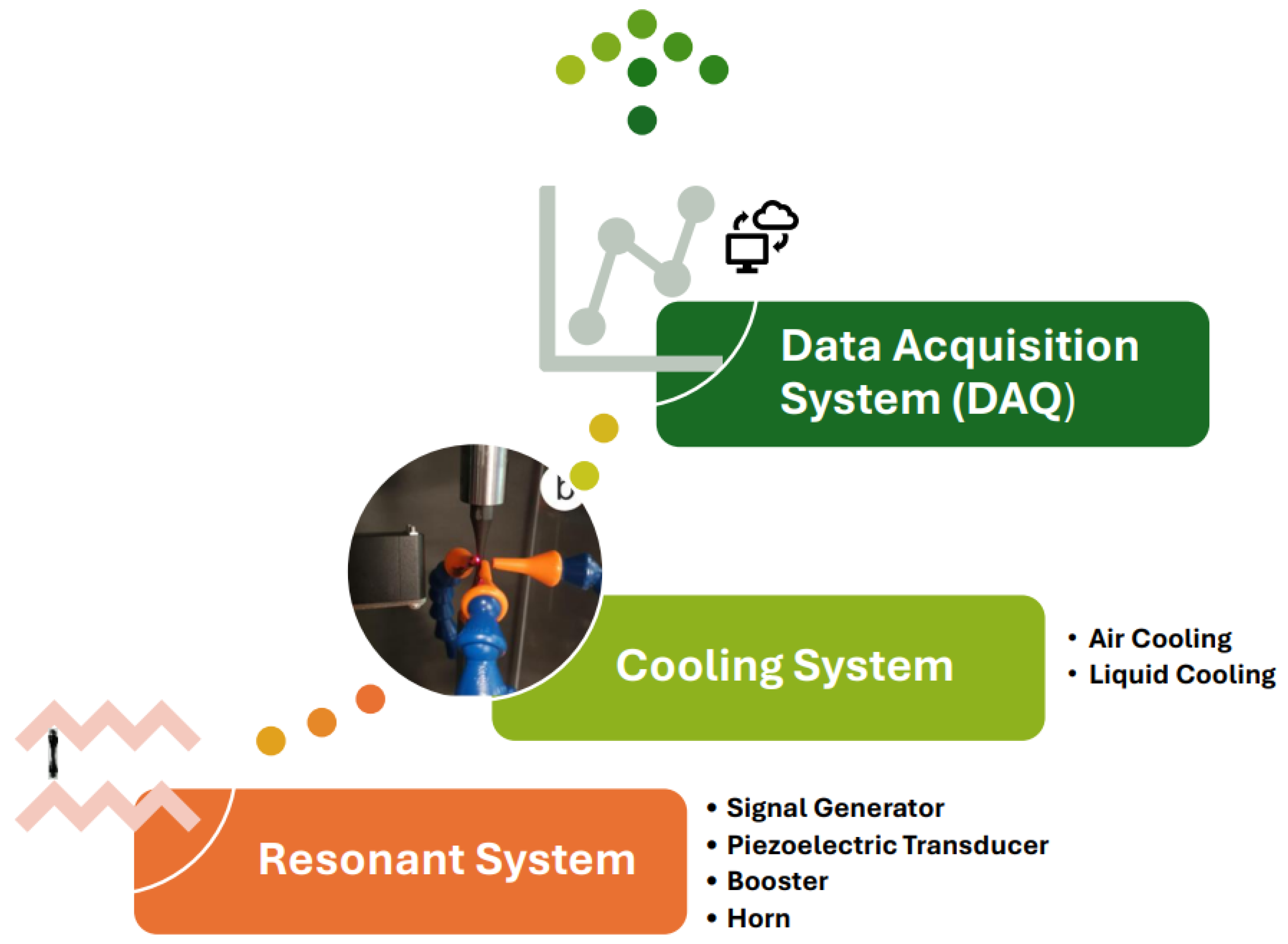
Key components of the UFT machine are illustrated in
Figure 6:
- 1.
Resonant System: Includes a signal generator, a piezoelectric actuator, a booster, and an amplifier horn.
Signal Generator—Transforms a 50 Hz or 60 Hz mains voltage signal into a 20 kHz sinusoidal electrical signal. Controls the displacement amplitude and ensures the system operates in resonance [
26].
Piezoelectric Transducer—Converts the electrical signal into longitudinal ultrasonic waves and mechanical vibrations at the same frequency [
8].
Booster and Amplifier Horn—Increases the vibration amplitude from the small range (5 µm to 20 µm) produced by the piezoelectric transducer [
8].
- 2.
Cooling System: Due to internal friction, the temperature of the specimen can increase significantly during testing. To mitigate this, the specimen is typically cooled with clean and dry compressed air. In some cases, submerging the specimen in water provides better cooling [
27,
28].
- 3.
Data Acquisition System (DAQ): Provides displacement control and stores data via software.
3. Very High Cycle Fatigue Performance of Steels
The VHCF behaviour is characterised by the fatigue limit of a material being in the gigacycle region
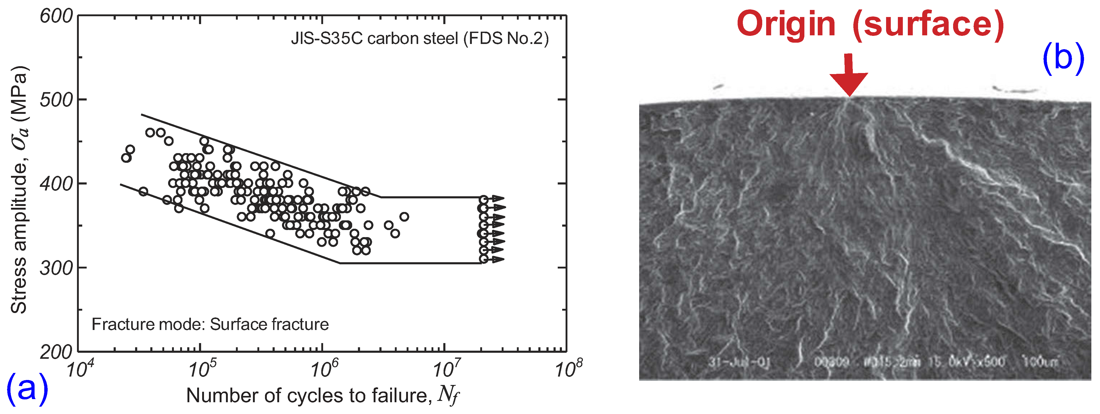
cycles. Conventional steels exhibit a well-defined fatigue limit as depicted in
Figure 7a. When the applied stress stays below this threshold, specimens can endure more than
loading cycles without failure, and fatigue cracks almost invariably originate at the component surface, as shown in
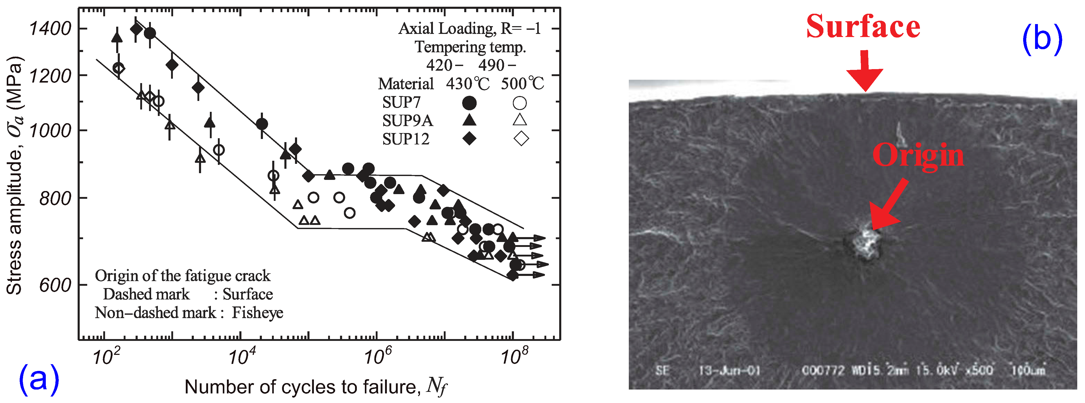
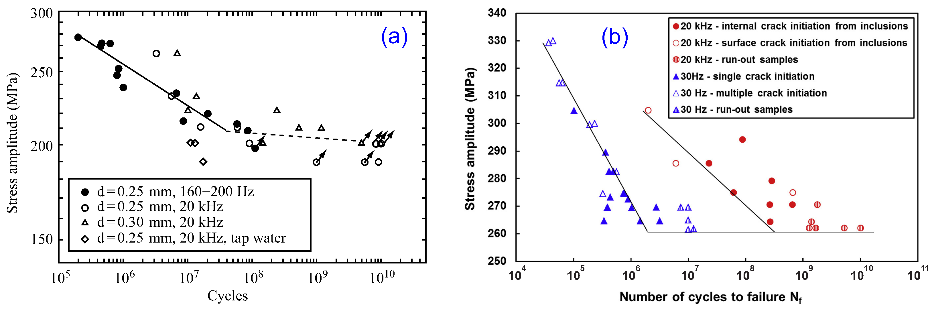
Figure 7b. HSS, however lose that distinct limit in the VHCF domain, as shown in
Figure 8a. Their fatigue limit is shifted into the gigacycle region, so failures can occur at cycle counts well beyond
and into the gigacycle range
, a phenomenon commonly referred to as gigacycle fatigue [
7]. While HSS may still develop surface-initiated cracks at relatively low cycle numbers, once the VHCF regime is entered, the dominant failure mechanism switches to internally initiated cracks that typically nucleate at non-metallic inclusions embedded within the bulk material, as shown in
Figure 8b. Summary of the VHCF test carried on the different grades of steel is listed in
Table 3.
3.1. High Strength Steels
Bathias [
29] showed that 20 kHz UFT rules out infinite fatigue life. The S–N curve drops almost 60 MPa between
–
cycles, with crack initiation shifting from surface at ≤
cycles to internal inclusions in the gigacycle regime (≥
) in HSS. The S–N curve for HSS is stepwise, reflecting both surface and internal crack mechanisms influenced by environment, cyclic strain ageing, and surface conditions [
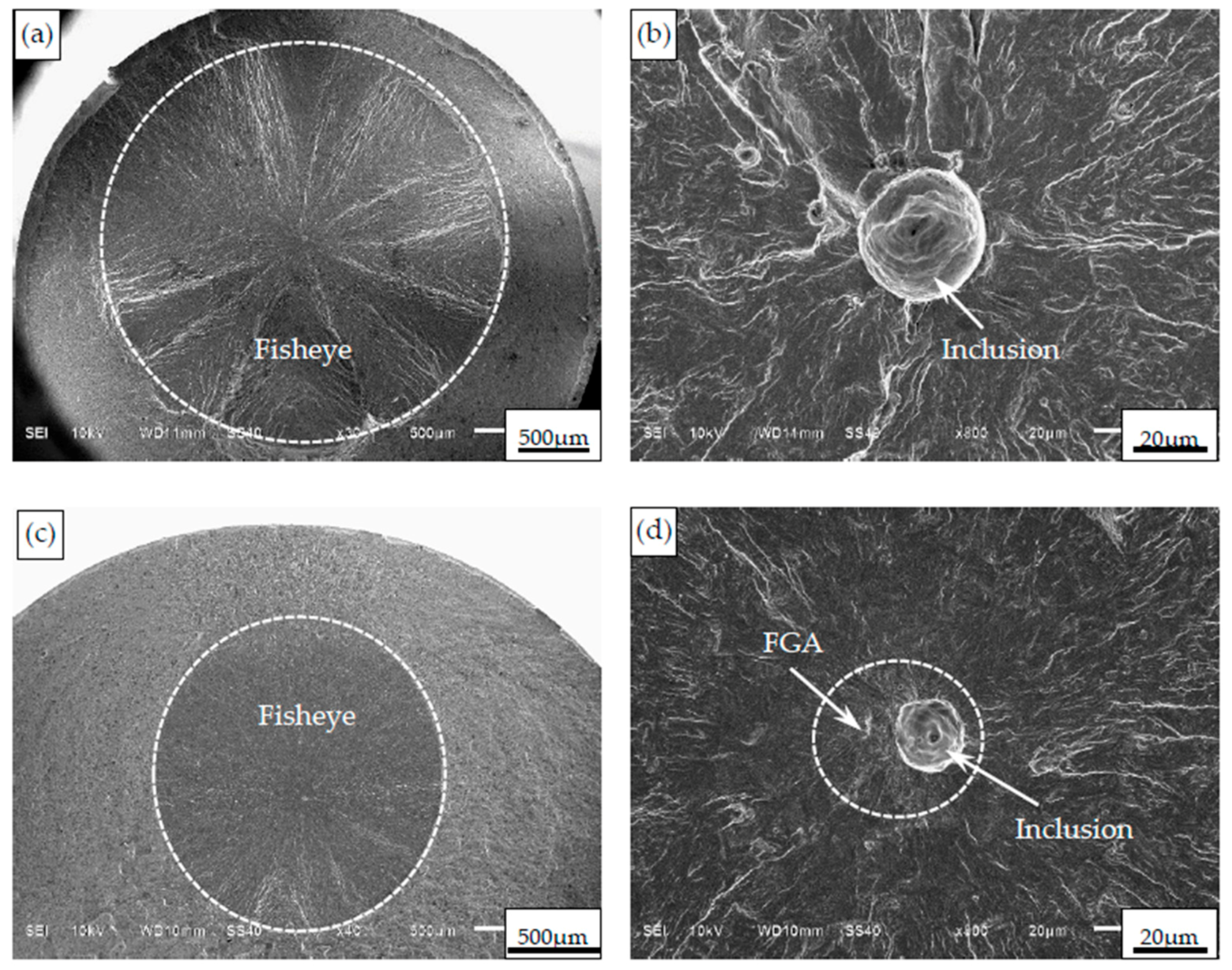
38]. Samples failing by internal crack initiation show a characteristic “fisheye” on the fracture surface surrounded by the Optically Dark Area (ODA) [
32,
39,
40]. ODA, when subjected to fractographic examination, reveals a characteristic fine granular morphology, commonly referred to as the fine granular area (FGA) or granular bright facet (GBF).
Figure 9a–d demonstrates that fatigue cracks initiate from interior non-metallic inclusions, producing fisheye features. The formation of (FGA) around the inclusion occurs only in the long-life regime,
cycles, while it is absent at shorter fatigue lives.
Various reasons have been put forward to explain the formation of the FGA observed on fracture surfaces in the VHCF regime [
42,
43,
44]. The proposed mechanisms include hydrogen-assisted cracking caused by hydrogen trapped at nonmetallic inclusions [
45], interfacial fracture between carbide particles [
14] and the matrix, and the formation of a fine granular layer through localised polygonization and de-bonding between inclusions and the surrounding matrix [
46,
47]. Pineau et al. [
48] underscored that further investigation into hydrogen-assisted interface embrittlement is needed, as the threshold hydrogen content and its dependence on microstructural parameters remain largely uncertain.
Mughrabi [
49] classified materials as Type I (pure, defect-free metals and alloys) and Type II (industrial alloys containing defects). In Type I materials, fatigue crack initiation in the VHCF regime arises from the irreversible portion of cyclic plastic strain. Over more than
cycles, subtle non-recoverable dislocation motions during repeated glide gradually produce surface roughness. The progressive accumulation of this localised plasticity ultimately promotes crack initiation at microstructural sites of stress concentration. The location of crack initiation has been shown to vary depending on the microstructural characteristics of the material. In multiphase steel with bainite and martensite [
39,
47] and martensite and ferrite in the matrix [
50], the subsurface non-defect fatigue crack origins were due to the material damage in the soft phase as a result of cyclic plastic deformation.
3.2. Conventional Strength Steels
Recent studies using UFT have revealed critical insights into the VHCF behaviour of low and medium strength steels, also called CSS. Zettl et al. [
51] reported that in low-strength normalised carbon steels (Ck15 and Ck60), fatigue cracks predominately initiate at the surface, unlike the subsurface inclusion-induced failures typically observed in HSS. A slope change in the S–N curve was noticed around
cycles, and no failures beyond
cycles, indicating VHCF is driven by cyclic plasticity rather than internal inclusion.
Gorash et al. [
36] highlighted the significant influence of defects, such as weld porosity and corrosion pits, on reducing the fatigue life in S275JR + AR and S355JR + AR steels. Higher testing frequencies in the ferritic steels increase the fatigue limits with surface crack initiation, due to low strength and localised heating near crack tips affecting the fracture behaviour [
37,
52]. Bach et al. [
53] emphasised the role of microstructure, showing ferrite-rich steels delay VHCF failure while pearlite-rich steels limit crack growth. In CSS, the fatigue limit is half of the yield strength. Duan et al. [
54] studied low alloy SNCM439 steels with identical composition but different tensile strength (1010 MPa and 1710 MPa). The lower-strength ferrite-pearlite steel showed only surface initiation and no VHCF failures beyond
cycles, whereas the HSS tempered martensitic steels exhibited subsurface inclusion-induced failures, often with fisheye features. This demonstrates that tensile strength and microstructure govern the transition from surface to subsurface crack initiation in the VHCF fatigue regime.
The contrasting fatigue responses of HSS and CSS under VHCF conditions demonstrate that fatigue life is influenced by a complex interplay of material characteristics and testing conditions rather than strength alone. Shiozawa et al. [
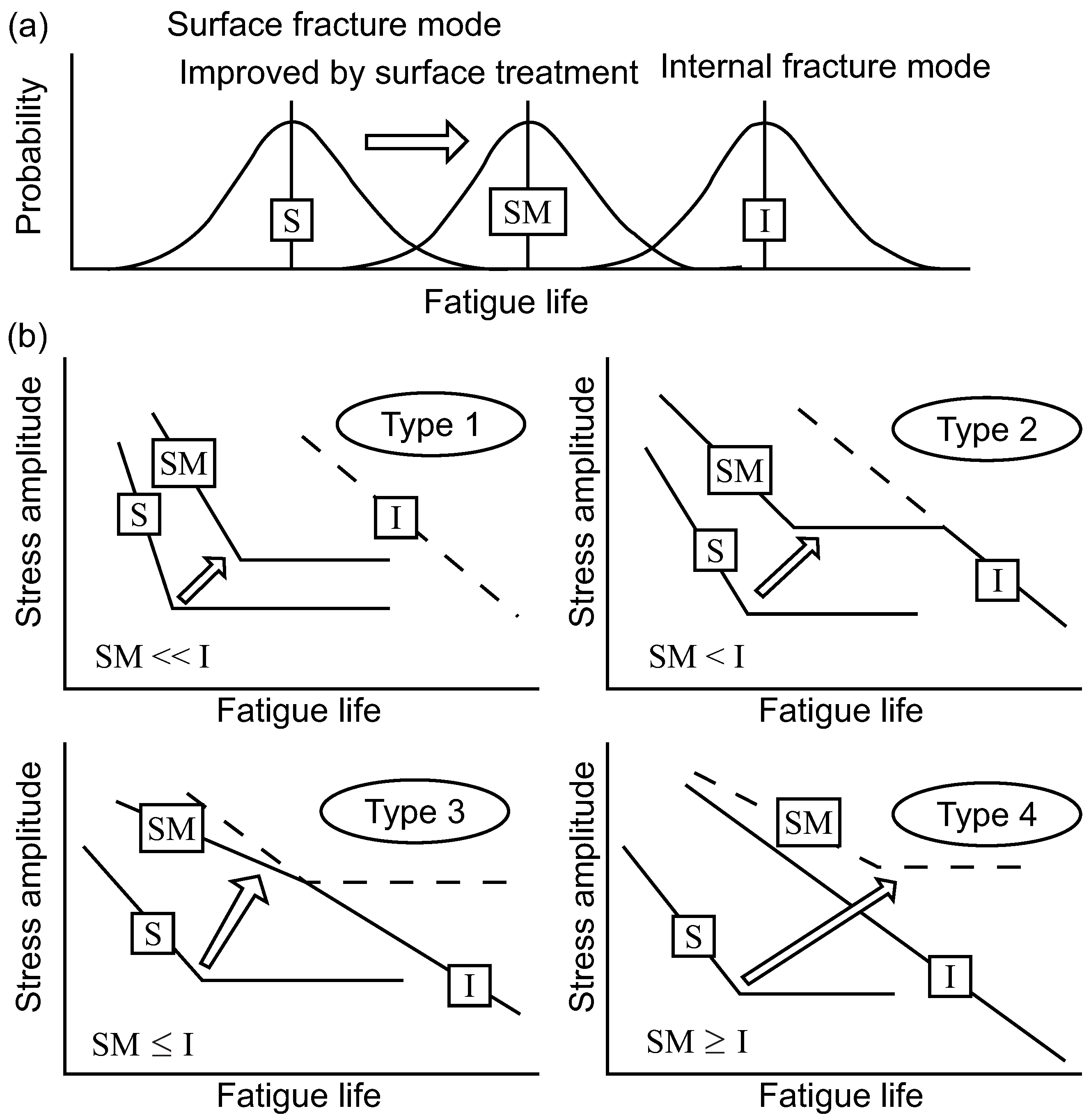
55] proposed the splitting of metals into four categories based on the relative position of the probability distributions for surface and internal fatigue fracture modes shown in
Figure 10.
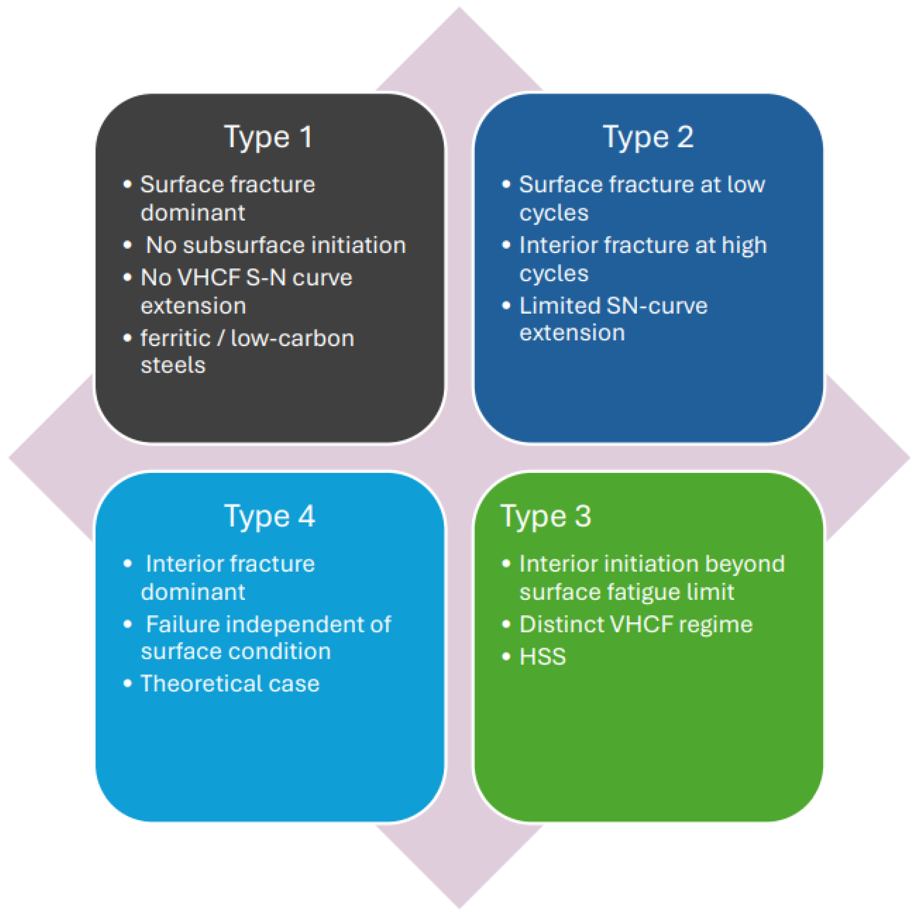
Type 1 [
55] in
Figure 10, materials represent metals in which the surface fracture mode occurs at a significantly lower number of cycles than the interior fracture mode. As a result, no subsurface failure will occur, and correspondingly, there is no extension of the S–N curve beyond the surface failure fatigue limit. Ferritic and low-carbon steels are of the Type 1 [
55] in
Figure 10. HSS fall under Type 2 and 3 [
55] in
Figure 10, where interior fracture will occur at only slightly higher numbers of cycles than the surface fracture mode. Such fracture initiation readily transitions to interior failure when the surface fatigue limit plateau is reached. Type 4 [
55] in
Figure 10 represents a theoretical metal in which the interior fracture mode occurs at a small number of cycles, as the surface fracture mode, thereby resulting in all failures originating from the subsurface, regardless of the stress amplitude, as summarised in
Figure 11. In ferritic low-carbon steels, fatigue cracks predominantly initiate at the specimen surface, independent of fatigue life. At conventional frequencies, crack initiation commonly occurs from persistent slip bands (PSBs) within ferrite grains, whereas under ultrasonic, loading PSB formation is often strongly reduced or suppressed, with cracks preferentially initiating along grain boundaries. The presence and role of PSBs depend on both loading frequency and microstructure. Some ferritic steels exhibit PSBs at both conventional (0.2–140 Hz) and ultrasonic (20 kHz) frequencies, though the number of PSBs is much lower at ultrasonic frequency, whereas other steels (e.g., C45E) show no PSB formation and cracks initiate exclusively along grain boundaries [
35,
56,
57]. However, the application of UFT introduces certain experimental challenges that can significantly affect fatigue results, which are discussed in the next section.
3.3. Experimental Considerations in Ultrasonic Fatigue Testing
3.3.1. Effect of Loading Frequency
Loading frequency is one of the most influential parameters in UFT, directly affecting the strain rate, temperature rise, and the underlying fatigue mechanisms. At ultrasonic frequencies ≈20 kHz, strain rates are several orders of magnitude higher than in conventional fatigue tests (10–100 Hz), which can significantly alter dislocation motion, cyclic plasticity, and crack initiation behaviour.
Hong et al. [
58] demonstrated that frequency effects are fundamentally tied to strain-rate sensitivity and crystal structure. Low-strength, body-centered cubic (BCC) steels exhibit a pronounced increase in fatigue strength at ultrasonic frequencies due to restricted dislocation glide, while HSS show a diminished frequency effect. Conversely, face-centered cubic (FCC) materials are largely insensitive [
59] because of easier dislocation motion, and hexagonal close-packed (HCP) alloys show moderate dependence governed by cyclic stress and material strength, as shown in
Figure 12.
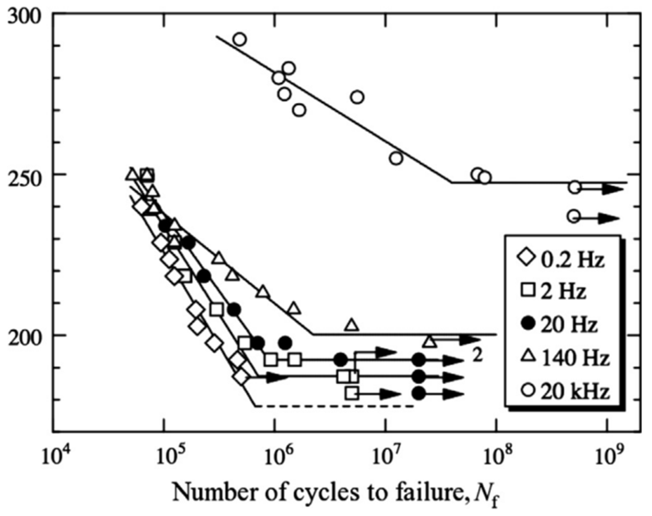
Experimental studies on JIS S15C low-carbon steel [
35], fatigue life increases with frequency, as shown in
Figure 13, with crack initiation transitioning from intragranular slip-band cracking at 15 Hz to intergranular cracking dominated by screw dislocation rearrangement at 20 kHz. Similar trend was observed in S275JR + AR steel, where higher apparent fatigue strength at 20 kHz was influenced by surface condition and pre-corrosion [
36] and in Q355B steel with ferritic microstructure, ultrasonic frequencies increased fatigue limits due to strain-rate hardening, though localised heating near crack tips also affected fracture behaviour [
37]. Hu et al. [
57] quantified these effects using the Johnson-Cook model, linking strain rate and temperature rise to changes in material strength.
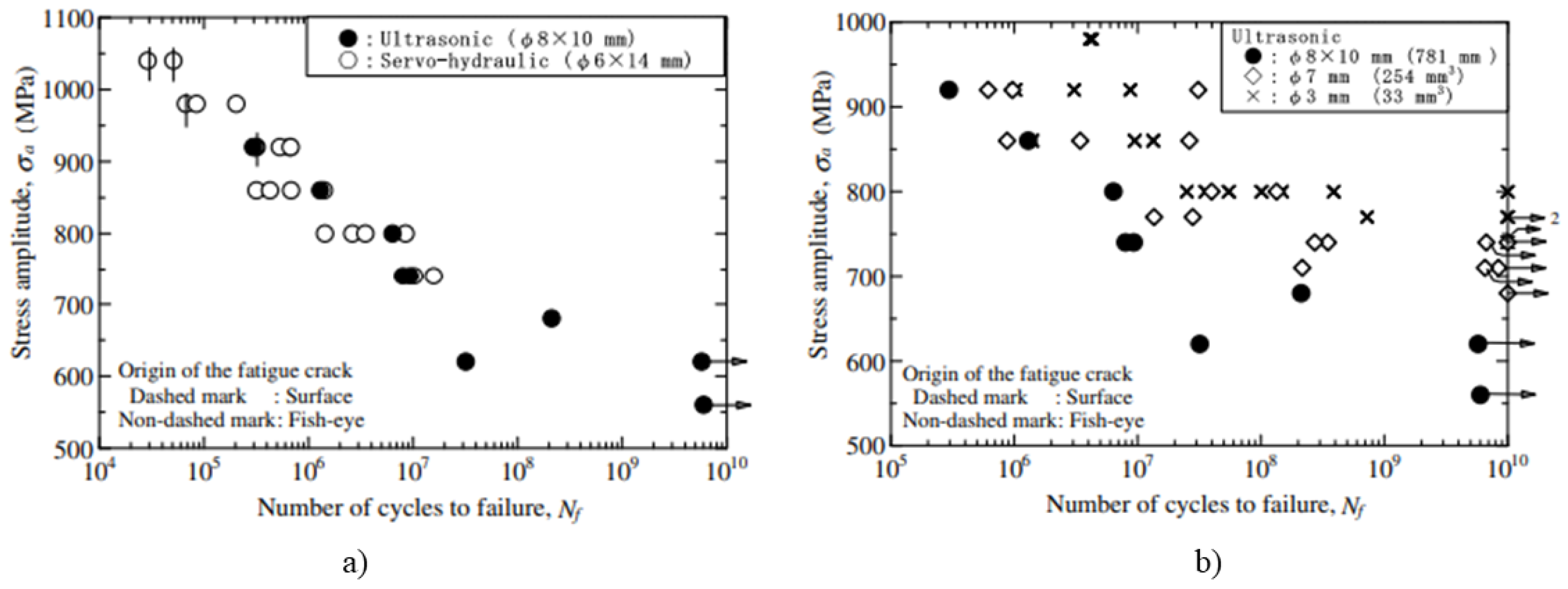
In the VHCF regime, BCC and body centred tetragonal (BCT) steels exhibit pronounced loading frequency sensitivity, as shown in
Figure 12b and
Figure 13, whereas FCC materials are largely frequency insensitive depicted in
Figure 12a. In BCC/BCT steels, higher frequencies generally increase fatigue life or strength due to the strain-rate effect.
The influence of loading frequency on fatigue behaviour is governed by strain-rate sensitivity, microstructural response, and temperature rise during high frequency loading. Low-strength BCC steels and many structural alloys exhibit a noticeable increase in apparent fatigue strength at ultrasonic frequencies, whereas the HSS and FCC alloys show minimal sensitivity [
61]. HCP alloys display an intermediate response that varies with cyclic stress and microstructural stability. In addition, the localised heating that accompanies very high-frequency loading can further alter fatigue behaviour by affecting dislocation motion and promoting cyclic softening. Consequently, frequency effects observed in UFT tests are not universal—they are highly material specific. Understanding the interaction among strain-rate effects, thermal influences, and underlying deformation mechanisms is essential when interpreting VHCF data obtained from ultrasonic testing.
3.3.2. Size Effect
Following the discussion on frequency, another key parameter influencing gigacycle fatigue behaviour is specimen size, commonly expressed in terms of risk volume—the highly stressed region, where fatigue damage initiates. The size effect reflects the statistical probability of encountering a critical defect within this volume. As specimen size or risk volume increases, the likelihood of large inclusions acting as crack initiation sites also rises, leading to a measurable reduction in fatigue strength. This phenomenon is particularly significant in VHCF regimes, where internal inclusions frequently govern crack initiation and failure mechanisms.
UFT of high-strength JIS-SCM440 steel [
62] demonstrates this trend: enlarged specimens with greater risk volumes exhibited up to a 25% decrease in gigacycle fatigue strength, as shown in
Figure 14, due to the increased probability of encountering large inclusions acting as crack initiation sites, validating the relevance of risk volume in VHCF regimes. Subsequent investigations on commercial spring steel [
63] confirmed similar behaviour. Larger specimens showed more severe degradation (20–25%) in VHCF strength, associated with increased oxide-type inclusion sizes at fracture origins. These studies emphasised that the size effect in VHCF is primarily driven by inclusion statistics, as larger volumes statistically contain rarer but more damaging inclusions, leading to earlier internal crack initiation. Similarly, design strategies, such as the Gaussian specimen shape, have been proposed to achieve larger risk volumes with uniform stress distribution, enabling systematic assessment of size effects in gigacycle fatigue tests [
64].
Experimental and literature studies indicate that size-effect in VHCF is strongly influenced by material type, manufacturing process and defect distribution within the risk volume. While larger specimens generally exhibit lower VHCF strength due to increased likelihood of critical defects, the effect varies depending on the defect size sensitivity and material properties. Specimen diameter or cross-section can also affect VHCF response, although risk volume remains the primary factor governing fatigue strength. Overall, tests on specimens with large risk volumes are recommended to accurately capture defect statistics and ensure reliable prediction of VHCF behavior in real components. A general predictive model is still lacking, emphasising the need for further experimental investigations to fully understand and quantify size-effect in VHCF.
3.3.3. Heating Effect
In UFT, the extremely high operating frequencies introduce unique thermal challenges that are absent in conventional fatigue testing. Testing at such high rates leads to self-heating of the specimen due to internal energy dissipation, which can significantly influence the measured fatigue behaviour. Infrared thermography studies have shown that this temperature rise is strongly affected by inter-related factors such as loading amplitude, intrinsic material properties and specimen geometry. Xue et al. [
65] observed an initial temperature increase followed by a quasi-steady plateau in AISI 52100, 42CD4 steels and GS51 cast iron, with localised spikes marking micro-plastic zones and early crack nucleation. Self-heating in VHCF is governed by specimen geometry, microstructure, and deformation behaviour. Short-gauge specimens develop higher local temperatures than long-gauge ones due to greater strain concentration, illustrating how geometry controls heat distribution [
66]. Pu et al. [
67] reported that steels with higher pearlite content (greater carbon) exhibit smaller temperature increments and higher fatigue strength, and identified abrupt temperature jumps associated with a transition from thermally activated to a thermal deformation linked to dynamic strain ageing.
Findings demonstrate that self-heating in VHCF is a multifactorial phenomenon. Accurate temperature monitoring and active thermal control are essential to distinguish intrinsic fatigue mechanisms from heating and to ensure reliable fatigue-life prediction.
3.4. Influence of Corrosion
The influence of corrosive environments on fatigue behaviour at ultrasonic frequencies has been widely investigated. Under common UFT, the effect of a corrosive medium is often less pronounced because the entire fatigue life is completed within a few minutes, providing insufficient time for significant surface oxidation or corrosion pit formation [
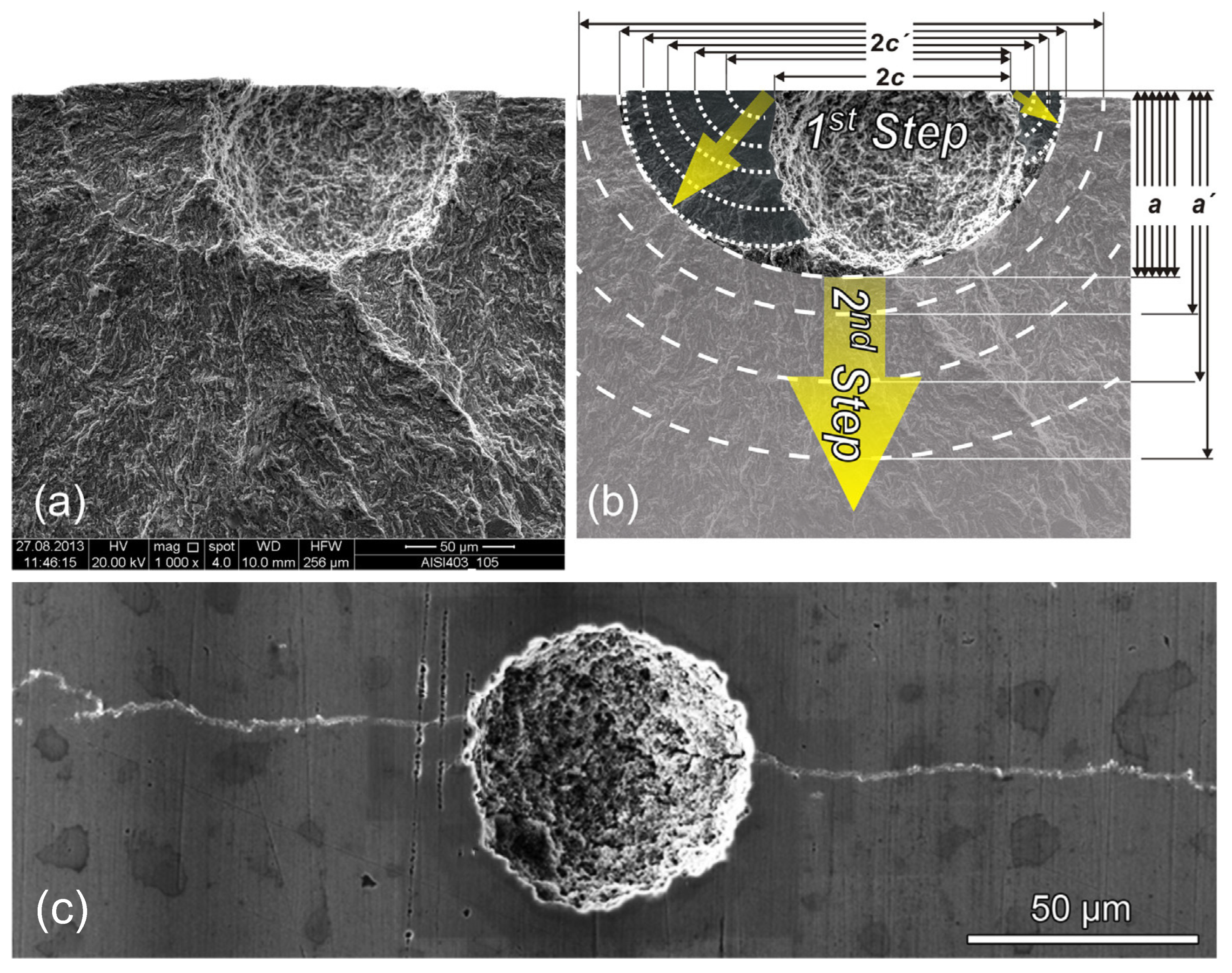
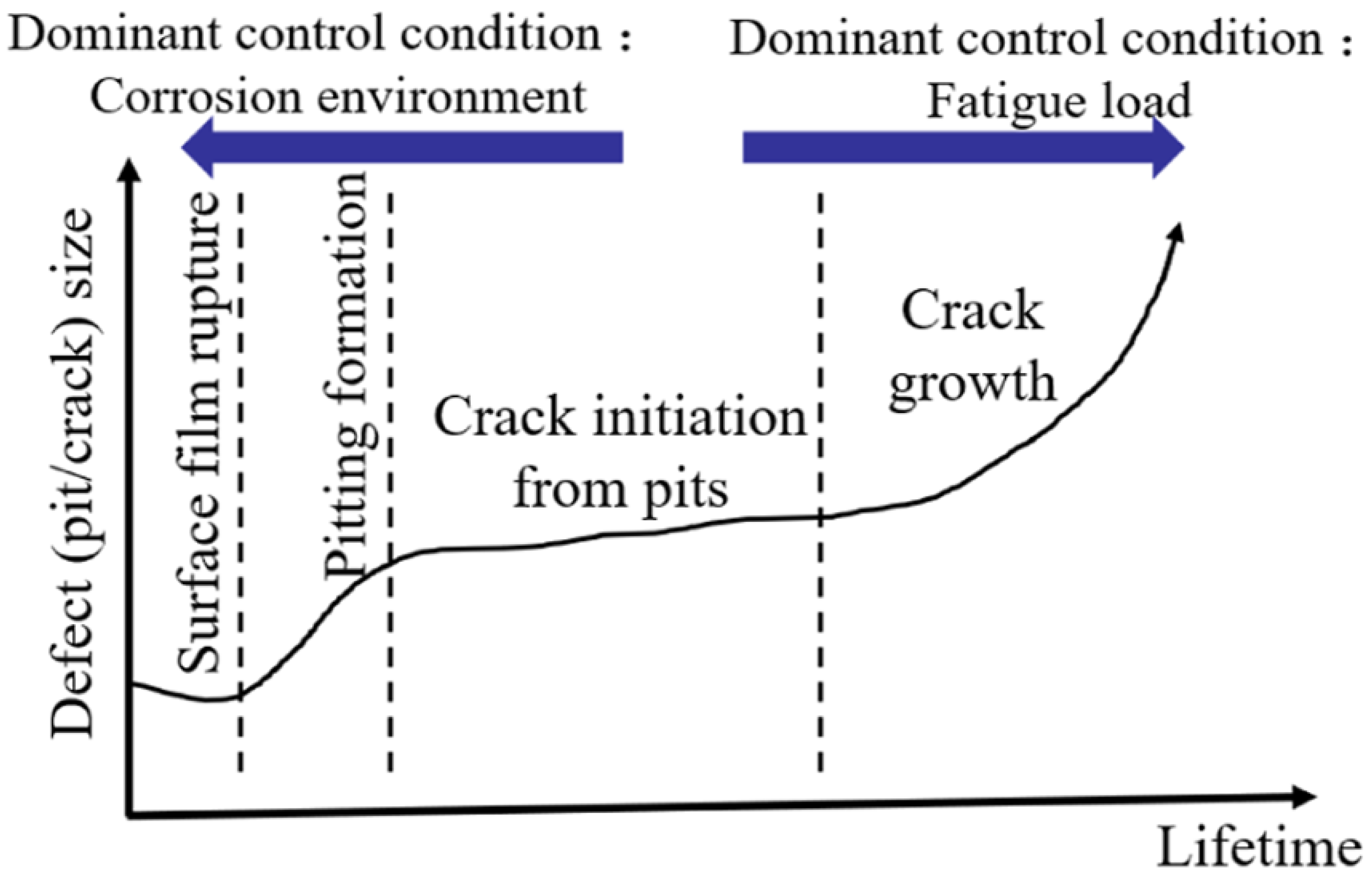
68]. Consequently, environmental effects may appear negligible under such conditions. However, when corrosion pit nucleation does occur, these pits act as severe stress concentrators and serve as preferential crack initiation sites, particularly in the VHCF regime, as shown in
Figure 15a–c.
Figure 15b shows the early crack growth from a corrosion pit, followed by the two-step crack growth from the pit to the crack. Once a critical pit geometry is reached, fatigue crack growth can be governed by the local stress intensity factor, highlighting the necessity of extended or in-situ corrosion–fatigue testing to capture realistic damage mechanisms.
Because of the difficulty of maintaining precise temperature control and avoiding cavitation on the specimen surface when testing in liquid media, most UFT corrosion studies employ either pre-corroded samples or artificially introduced corrosion pits [
70,
71,
72]. This strategy separates the time-dependent corrosion phenomena from the relatively brief fatigue test, which can improve the repeatability of results across different test frequencies. Perez-Mora et al. [
72] performed UFT tests on R5 steel while exposing the specimens to a flowing artificial seawater environment. Their S–N curves showed a marked decrease in fatigue resistance for the in situ corroded specimens, even though the test duration was short. The degradation was considerably greater than that observed for the pre-corroded specimens, and it became more pronounced as the number of cycles to failure and thus the test time increased. Similar findings were reported for S355JR and 34CrNiMo6 steels with substantial loss of fatigue strength under artificial seawater in UFT tests [
73].
Corrosion pits serve as the primary stress concentrators that trigger crack initiation and drive subsequent crack growth, especially under VHCF conditions, where locally elevated SIF dominate. Because of this, conducting realistic in situ ultrasonic corrosion-fatigue tests is crucial for accurate life prediction and damage-tolerant design. Advancing coupled mechanical-electrochemical testing methods will therefore be essential for developing more reliable predictive models and enhancing the durability of components that operate in corrosive, high-frequency environments.
3.5. Specimen Geometry
UFT specimen design is governed by the need to achieve resonance at the operating frequency while generating controlled stress states in the gauge region, as shown in
Figure 16. Depending on the attachment configuration and the desired loading condition, UFT specimens can be broadly classified into-single threaded uniaxial [
31], double-threaded uniaxial [
10], and multi-axial cruciform designs [
74]. Each configuration presents specific advantages and design challenges related to mode stability, stress distribution, and achievable loading conditions. A summary of the specimen types commonly adopted in the literature and their main design features is provided in
Table 4.
Single and double-sided uniaxial specimens remain the most reliable UFT designs due to their simple geometry, stable resonance, and well-controlled stress states, with double-threaded configurations enabling non-zero mean stress testing [
31,
36]. Cruciform specimens extend UFT to multi-axial loading but introduce significant challenges, including sensitivity to undesired vibration modes near the operating frequency and to manufacturing tolerances. Achievable stress levels are further limited by the need for impractically thin central regions, restricting their applicability for HSS. As a result, cruciform designs require careful optimisation and remain more restrictive than uniaxial specimens [
75].
3.6. Ultrasonic Fatigue Testing (UFT) Standards
UFT currently has limited standardization. An unofficial guideline was published in 2000 in the ASM Handbook [
76], describing the principles of UFT and general recommendations that remain in use, such as non-contact displacement measurement, forced convection cooling, and hourglass specimens. Some suggested practices, like hollow specimens or temperature-sensitive paint, have seen little adoption.
The only formal standard is WES-1112, published by the Japan Welding Engineering Society in 2017 [
77,
78]. It provides recommendations for machine capabilities, specimen design, test methods, and data reporting, while allowing flexibility in materials and test parameters. No international, European, or American standards currently exist [
79], and WES-1112 is rarely cited outside Japan. As such, reproducibility and comparability of UFT results remain limited.
4. Fatigue Crack Growth in Steels
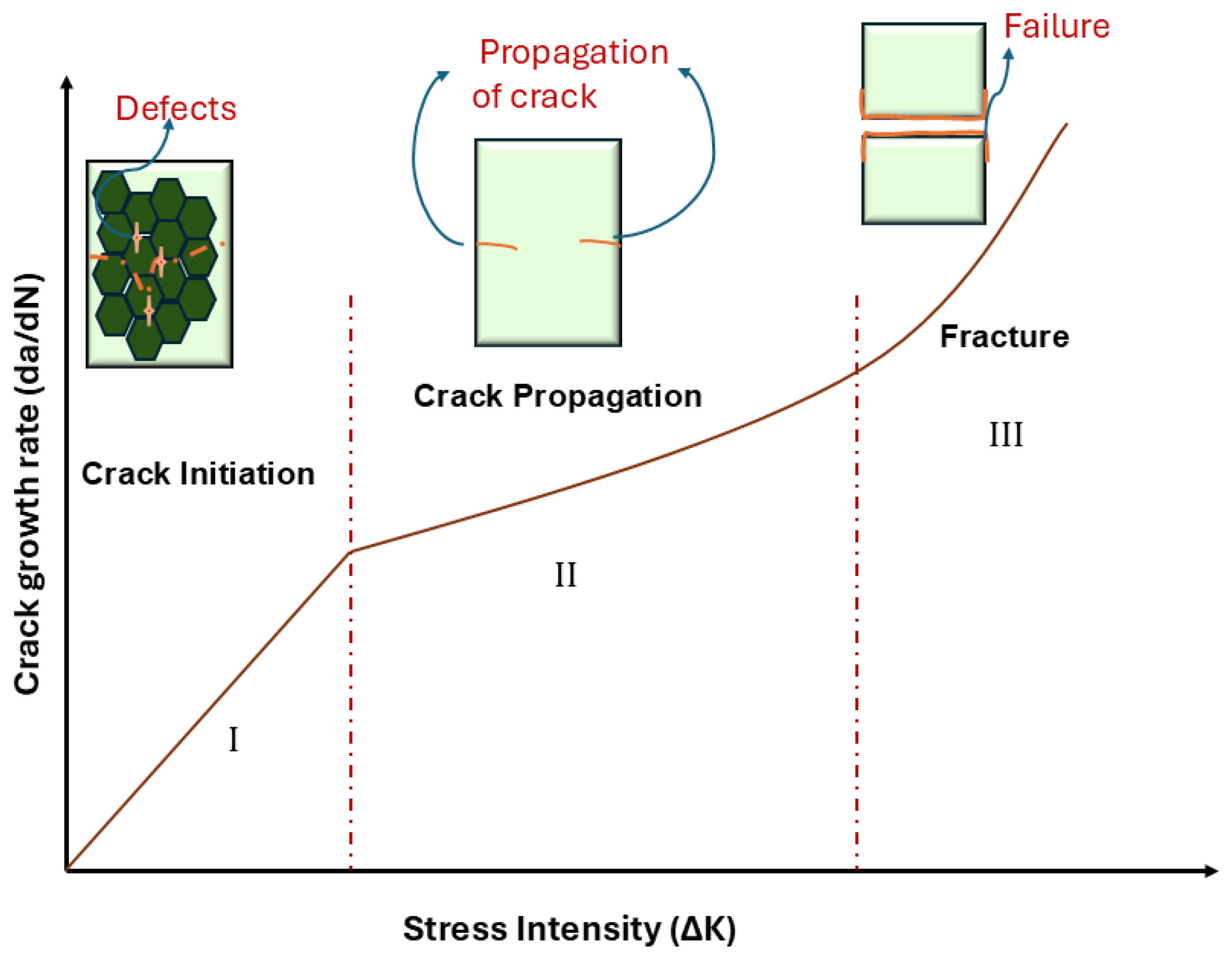
Fatigue failure in metals is commonly classified into three distinct stages, as illustrated in
Figure 17: (I) crack initiation, where a microscopic flaw often a manufacturing defect, material inclusion weld imperfection, or casting void—first nucleates; (II) stable crack propagation, during which the crack grows incrementally with each load cycle and typically consumes the majority of the components service life; and (III) final fracture, when the remaining ligament can no longer sustain the applied load. Because most engineering parts contain inherent defects, they spend most of their operational time in the propagation phase rather than in initiation.
The SIF (K) characterises the crack-tip stress field and reflects the combined effects of applied stress, crack length, and geometry. Originating from Irwin’s Linear Elastic Fracture Mechanics (LEFM) framework [
80], it is commonly expressed as
In fatigue, the crack-driving force is the SIF range K, which governs propagation behaviour in models, such as the Paris law. In ductile materials, the assumptions of LEFM break down due to pronounced plastic deformation depending on SIF at the crack tip.
Elastic Plastic Fracture Mechanics (EPFM) addresses this limitation by incorporating crack-tip plasticity. The development of an extended plastic zone promotes energy dissipation, thereby increasing resistance to crack propagation and leading to significantly higher fracture stress. Fatigue crack propagation in materials has been described using several fracture mechanics-based models. The Paris–Erdogan law relates the crack growth rate to the stress intensity factor range according to
and is mainly applicable to the stable, mid-growth regime under constant-amplitude loading [
81]. To incorporate mean stress effects, Walker [
82] proposed a modified form:
which explicitly accounts for the influence of the stress ratio (R). At higher stress intensity levels approaching fracture instability, the Forman equation introduces a dependence on fracture toughness:
providing improved accuracy in the high crack growth regime [
83]. More comprehensive formulations, such as the NASGRO model, combine threshold behaviour, stress ratio effects, and proximity to fracture within a unified framework, enabling crack growth prediction over a wide range of loading conditions [
84].
4.1. Factors Influencing Fatigue Crack Growth
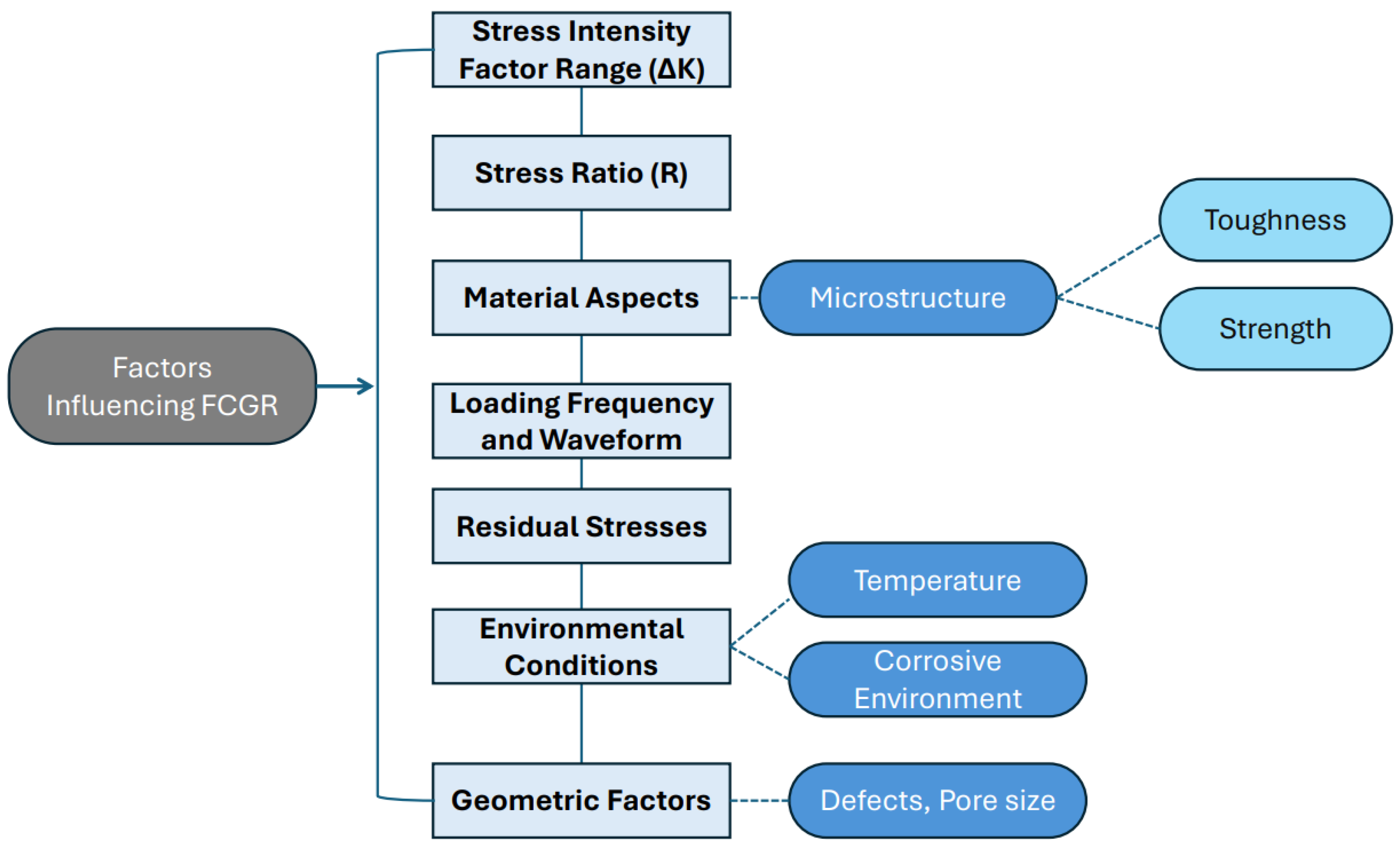
Fatigue crack growth (FCG) is a critical phenomenon that governs the durability and structural integrity of materials under cyclic loading. As shown in
Figure 18, multiple factors influence crack propagation, including material properties, processing methods, environmental conditions, and testing parameters. Given the broad scope of fatigue behaviour, this discussion focuses on material properties, welding, and environmental effects. Welding processes and environmental factors, such as temperature, humidity, and corrosive media, can interact with material microstructure and loading conditions to either accelerate or retard fatigue crack propagation. The following sections review the current understanding of these key factors and their combined effects on FCG in steels.
4.1.1. Effect of Microstructure
The fatigue behaviour of steel, particularly fatigue crack growth rate (FCGR), is strongly governed by microstructural characteristics, phase composition, loading conditions, and environment. Among these factors, grain size plays a dominant role. Fine-grained steels generally exhibit improved fatigue resistance due to the increased density of grain boundaries, which hinder dislocation motion and obstruct crack propagation. In contrast, coarse-grained microstructures offer fewer barriers to crack growth, making them more susceptible to fatigue failure depending on phase distribution and morphology.
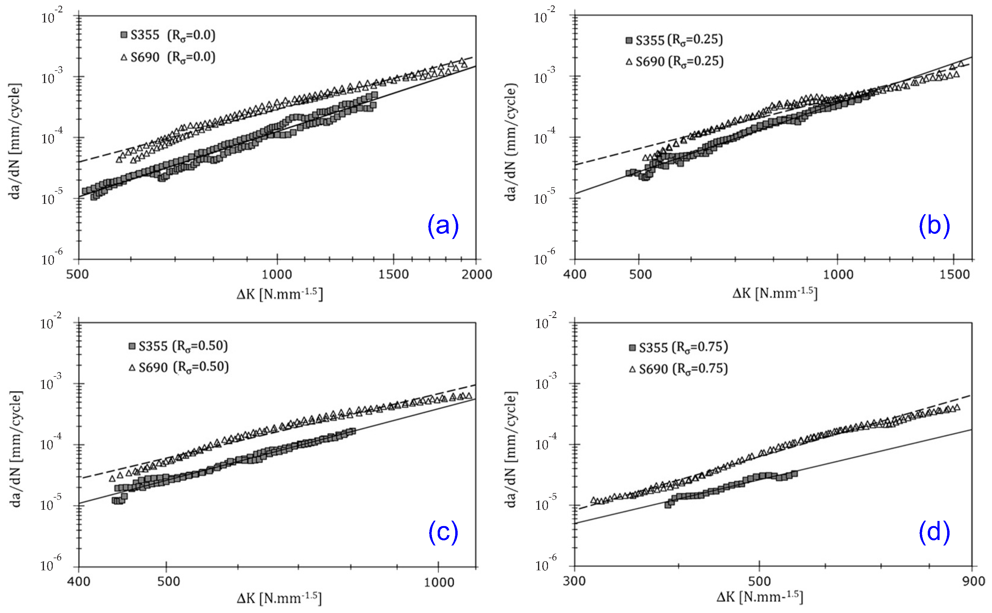
Several studies confirm that microstructure often outweighs strength level in controlling FCGR. Jesus et al. [
85] reported higher crack growth rates in S690 steel compared to S355 across all stress ratios, attributed to its finer, martensitic microstructure, as shown in
Figure 19. They also showed that FCGR increases with yield strength and stress ratio, while the fatigue crack growth threshold decreases linearly. However, Hesmati et al. [
86] demonstrated that microstructural effects are most pronounced in the threshold region, where grain orientation, Taylor factor, and grain boundary character dictate whether crack propagation is transgranular or intergranular. Notably, despite its higher yield strength, 700MCPlus exhibited the slowest FCGR, highlighting the dominant influence of microstructure over strength alone.
Phase constitution significantly alters crack propagation behaviour. Ferrite, being ductile, provides resistance to crack propagation but is more susceptible to crack initiation under cyclic loading. Pearlite strengthens the steel but may facilitate crack initiation at ferrite–pearlite interfaces. Martensite offers high strength and improved threshold resistance, yet its low ductility can promote brittle crack growth under certain conditions. Bainite provides an optimal balance between strength and ductility, offering superior resistance to both crack initiation and propagation, while retained austenite enhances fatigue resistance through transformation-induced plasticity.
Studies on high-strength Chinese grade bridge steels (Q370qE, Q420qE, and Q500qE) showed that finer grain sizes, higher strength grades, increased hard-phase content, and the presence of bainite significantly reduce FCGR compared to pearlitic structures [
87]. Crack path characteristics are also strongly influenced by microstructural barriers. In martensitic steels such as 18CrNiMo7-6, crack propagation is governed by grain boundaries, martensite lath boundaries, and crystal orientation changes, leading to crack deflection and retardation [
88]. The martensite lath has been identified as the fundamental structural unit controlling fatigue performance and small crack growth behaviour [
89]. In CSS, ferrite grains promote roughness-induced crack closure, delaying crack growth at early stages and at low
K values, where crack branching and deflection are commonly observed.
Stress ratio and environment further interact with microstructure to influence FCGR. At low stress ratios, enhanced crack closure and increased plastic deformation at the crack tip lead to rougher fracture surfaces and reduced crack growth rates. Summary of the microstructure effct on the FCGR is summarised in
Table 5. Environmental effects, such as corrosion fatigue and hydrogen embrittlement, can significantly degrade fatigue performance, with martensitic steels being more susceptible due to hydrogen trapping at fine grain boundaries. Bainitic and ferritic steels generally exhibit better resistance to such environmental degradation. Notably, fine martensitic grain structures provide more hydrogen trapping sites compared to coarser grains, further influencing FCGR [
90].
Overall, the interaction between grain size, phase morphology, crack path deflection mechanisms, and environmental sensitivity governs fatigue crack growth behaviour. Understanding these microstructural influences is critical for designing steels with enhanced fatigue resistance and extended service life.
4.1.2. Effect of Welding
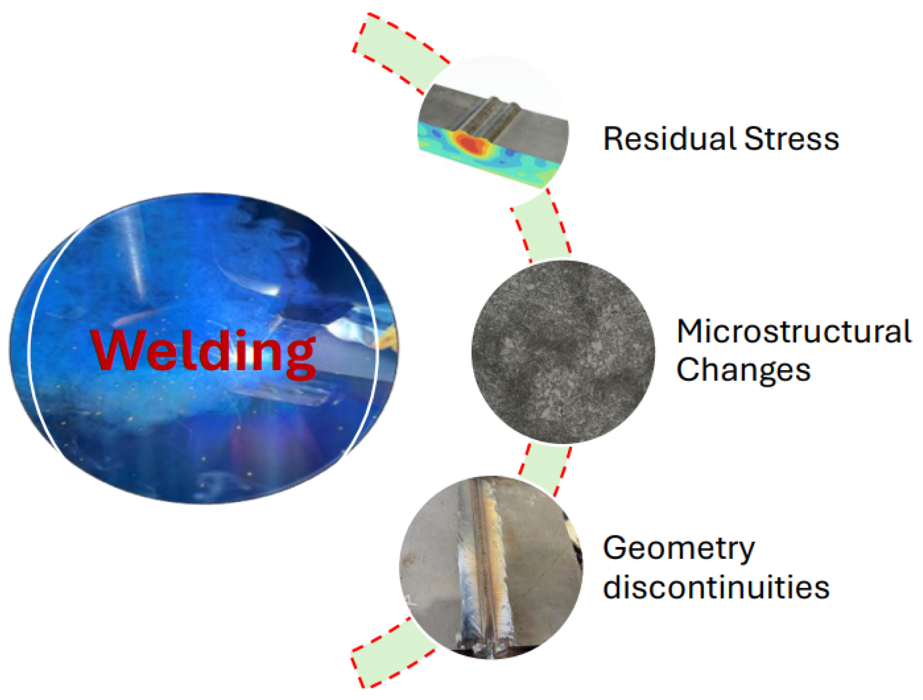
Welding plays a critical role in the fatigue performance of steel structures by altering local microstructure, introducing residual stresses, and creating geometric discontinuities as depicted in
Figure 20. These effects are particularly important in HSS and ultra-high-strength steels (UHSS), where welding-induced changes can significantly influence fatigue crack initiation and propagation behaviour. The quality and performance of a welded joint are governed by several interacting factors, including material composition, welding process, heat input, filler material selection, and environmental exposure. The chemical composition of the base material strongly affects weldability and fatigue performance. Alloying elements, such as carbon, manganese, and sulphur, influence hardness, phase transformations, and susceptibility to weld-related defects, including cracking.
Moe et al. [
94] reported that laser welding (LW) produces lower FCGR than gas metal arc welding (GMAW) in UHSS grades S700, S960, and S1100 due to reduced heat input and refined microstructures, with S700 base material showing the lowest FCGR. Filler metal strength mismatch is a critical design parameter in welded HSS joints. According to Lukacs et al. [
95], undermatching filler materials improve weld metal fracture toughness, reduce residual stresses, and enhance resistance to hydrogen-assisted cracking. Overmatching fillers are sometimes applied in lower strength HSS, such as S690, to satisfy static strength requirements, although their influence on fatigue resistance remains uncertain and requires further investigation. Filler selection must also consider weld location, particularly in load-carrying joints.
The heat-affected zone (HAZ), especially the coarse-grained HAZ (CGHAZ) and intercritically reheated CGHAZ (ICCGHAZ), is widely recognised as the most fatigue-critical region in thick welded plates. Bertolo et al. [
96] showed that grain coarsening and phase transformation in these regions reduce fracture toughness and promote cleavage-dominated failure. Excessive heat input exacerbates grain growth, while inadequate heat input may cause welding defects, such as a lack of fusion or porosity. Improper cooling can further promote brittle martensitic microstructures with increased susceptibility to hydrogen embrittlement [
90].
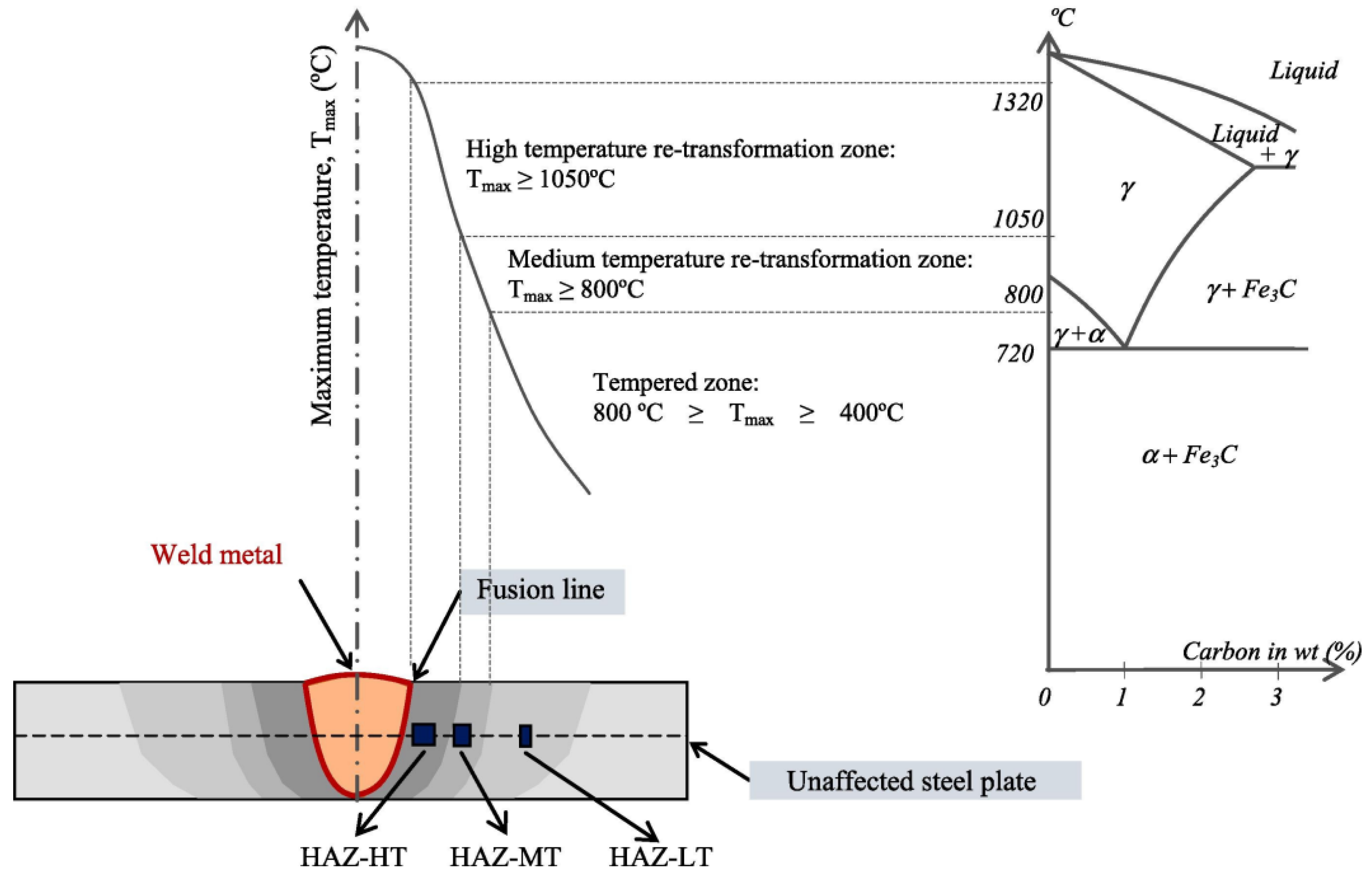
HSS are commonly produced by quenching and tempering, and welding thermal cycles induce complex phase transformations in the weld metal and HAZ, including the formation and tempering of martensite, bainite, and ferrite, as illustrated schematically in
Figure 21. These transformations strongly influence local hardness, residual stress distribution, and fatigue crack growth behaviour.
Advanced low-heat-input welding processes, such as laser welding, hybrid welding, and controlled GMAW, are therefore preferred for HSS to limit CGHAZ formation and reduce hydrogen-assisted cracking, in line with standards. CSS such as S275 and S355, with stable ferritic or ferrite–pearlite microstructures, are less sensitive to welding-induced degradation. Residual tensile stresses and weld imperfections further accelerate fatigue crack initiation and increase the effective stress ratio at the crack tip. The key differences between the welding of HSS and CSS is shown in
Table 6.
Overall, FCGR in welded steel joints is governed by the combined effects of HAZ microstructure, phase transformation, filler metal mismatch, residual stresses, and welding process control. Optimised welding procedures are essential to ensure adequate fatigue performance of high-strength steel structures.
4.1.3. Effect of Corrosion
Metallic components operating in harsh, chemically aggressive environments are inherently susceptible to corrosion, with localised corrosion being particularly detrimental due to the formation of isolated regions of severe material loss. When such localised corrosion interacts with cyclic mechanical loading, the fatigue life of components can be drastically reduced, often leading to failure at stress amplitudes significantly lower than those measured in air, as shown in
Figure 22. This pronounced reduction in fatigue performance is primarily attributed to the early initiation of cracks at corrosion pits, which act as potent stress concentrators. Consequently, a quantitative description of pit geometry and its influence on crack nucleation is essential for evaluating corrosion-induced fatigue degradation [
5].
Although life-prediction models based on LEFM can provide reasonable estimates of fatigue life, they generally fall short of capturing the physical processes governing the transition from a corrosion pit to a propagating fatigue crack. This limitation has been highlighted across a range of steel systems. For example, studies on high-strength AISI 4340 steel have shown that corrosion fatigue crack growth is strongly governed by threshold-controlled behaviour, with significant environmental acceleration occurring only when the maximum SIF exceeds the stress corrosion cracking threshold,
, indicating a distinct pit-controlled crack initiation regime before long-crack propagation dominates [
105]. Similarly, investigations on offshore monopile weldments have demonstrated that fatigue crack growth rates in free corrosion seawater are consistently higher than in air, even for modern steels, confirming the inability of conventional air-based fatigue models to describe corrosion-assisted damage evolution [
17].
The recognition of pitting corrosion induced fatigue as a distinct failure mode therefore underscores the inadequacy of traditional fatigue life methodologies, which often neglect the synergistic interaction between corrosion damage and cyclic loading. Experimental evidence from structural marine steels further confirms this interaction, as corrosion FCGR in seawater is strongly influenced by loading waveform, frequency, and microstructure, with sine-wave loading producing higher crack growth rates than hold time loading due to reduced crack-tip blunting. Thermo-mechanically controlled processed (TMCP) steels exhibit superior resistance compared with normalised steels, highlighting the critical role of microstructural design in mitigating pit-induced fatigue damage [
106].
Pit evolution is governed by intrinsic material properties, the electrochemical environment, and the applied stress state. Once corrosion pits form, they act as natural stress concentrators and preferential sites for fatigue crack initiation, markedly reducing fatigue life. The rate of pit enlargement is closely coupled to the extent of local plastic deformation; pit growth accelerates once plasticity is activated and may reach a steady-state condition when plastic deformation saturates at stress levels exceeding the material yield strength. This behaviour is particularly evident in advanced high-ductility steels, such as twinning-induced plasticity (TWIP) steels, where localised plastic deformation at grain and twin boundaries promotes anodic dissolution and accelerates pit-to-crack transition, while uniform plastic deformation can partially suppress localised corrosion fatigue damage [
107].
The critical phase of corrosion fatigue is the pit-to-crack transition, followed by early crack propagation, which dominates the overall fatigue life under corrosive conditions [
108,
109,
110]. This has been clearly demonstrated in corroded HSS weldments, where corrosion pits and weld defects act as dominant crack initiation sites. Experimental studies on Q690 high-strength steel butt welds exposed to simulated marine splash-zone conditions have shown fatigue-limit reductions of up to 30–35%, with fracture analyses revealing accelerated crack propagation due to severe stress concentration at corrosion-damaged regions [
5]. In offshore monopile weldments, both base metal and heat-affected zone exhibit similar corrosion fatigue crack growth trends, indicating that environmental effects can outweigh local metallurgical differences once pit-induced cracking is activated [
17].
5. Numerical Analysis Approach in Fatigue
Numerical analysis plays a crucial role in UFT, when tested in the VHCF regime, where components are subjected to over
cycles at high frequencies, typically around 20 kHz. UFT requires the entire testing assembly, including the piezoelectric actuator, booster, horn, and sample, to resonate in harmony. Accurate prediction of resonant frequencies, mode shapes, and stress distributions is therefore essential for reliable experimentation, stress calibration, and interpretation of fatigue behaviour. The works of da Costa et al. [
111,
112] have demonstrated that numerical methods are necessary for designing and validating ultrasonic fatigue experiments, particularly when addressing complex geometries and multi-axial loading conditions.
Thermo-mechanical effects have likewise been studied numerically. Bach et al. [
66] demonstrated that specimen geometry strongly influences strain localization, temperature rise, and frequency reduction during ultrasonic loading. Numerical analysis has been shown to aid in detecting fatigue crack initiation through changes in resonant frequency and mode shape [
113].
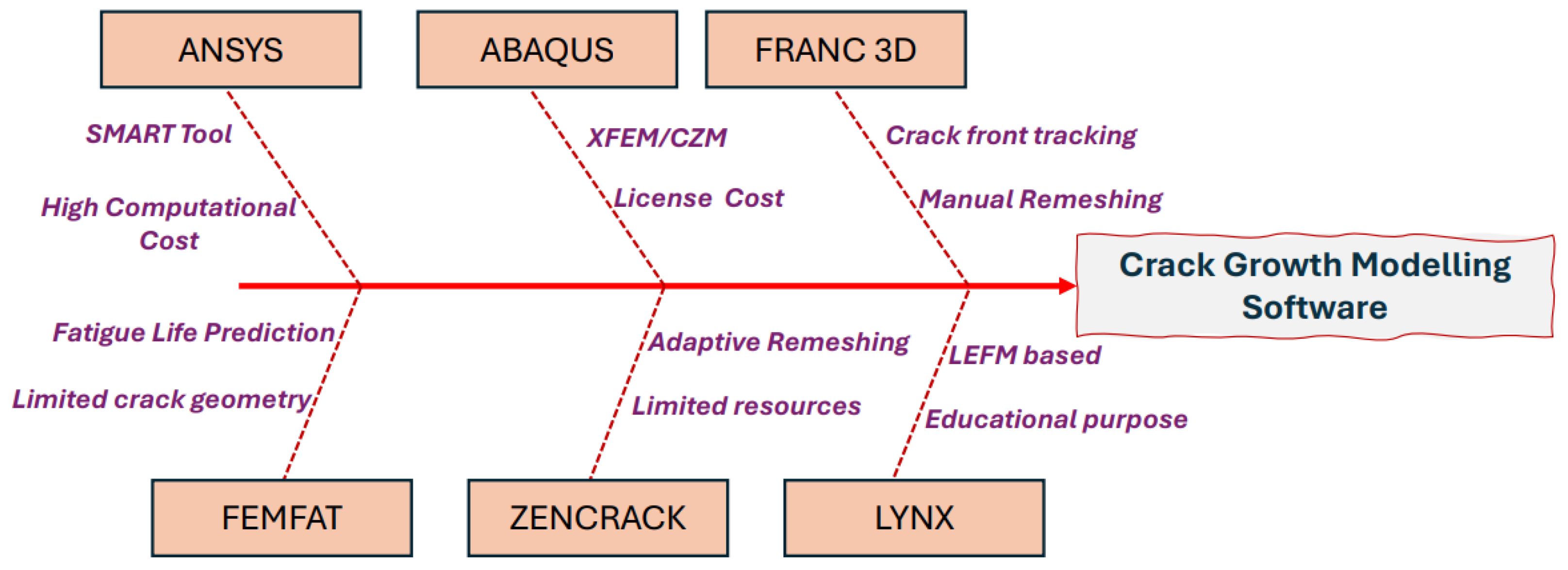
Fatigue crack growth software is crucial for forecasting crack initiation and propagation under cyclic loading, thereby safeguarding structural integrity. Popular crack growth software is listed in
Figure 23. Range of employ a range of numerical techniques, including XFEM, VCCT, cohesive zone modelling, SIF calculations, and phase field methods, are used to capture complex 3D crack behaviour.
ABAQUS [
114] and ANSYS [
115] provide versatile FE environments with comprehensive crack growth capabilities.
FRANC3D [
116] and ZENCRACK [
117] specialise in detailed crack-front analyses.
FEMFAT [
118] focuses on industrial-scale fatigue-life prediction.
LYNX [
119] offers fast crack-propagation modelling for standard geometries.
COMSOL [
120] enables the coupling of fatigue phenomena with multiphysics effects.
Despite their strengths, these packages share common limitations—sensitivity to mesh quality, high computational cost, a limited selection of material models, and challenges in representing highly intricate crack paths or complex geometries. Selecting the most suitable software depends on the desired level of accuracy, the complexity of the problem, and the computational resources availability [
121].
Recent investigations have shown that numerical simulations can effectively capture fatigue crack growth behaviour in a variety of steel grades. In particular, researchers have employed ANSYS Workbench together with the SMART tool to model crack propagation in compact tension (CT) samples [
18,
19,
122]. By linking the simulated crack mouth opening displacement (CMOD) and back face strain (BFS) to the evolving crack length, the FE models were calibrated against experimental measurements [
123]. Using Paris law coefficients derived for structural steels, including CSS and HSS, the simulations produced crack growth rate predictions that closely matched laboratory results. Although the approach performed well overall, it revealed greater uncertainty at low SIF ranges and under complex loading histories. Nonetheless, these FE techniques offer reliable estimates of crack growth behaviour, substantially reducing the reliance on exhaustive experimental testing.
6. Total Life Approach
The total life approach to fatigue life prediction considers the complete fatigue process as a combination of crack initiation and crack propagation, providing a more comprehensive estimation than methods focusing on only one stage. In VHCF, crack initiation often dominates the total life, whereas in HCF and LCF crack propagation can become more significant [
124,
125]. By integrating both stages, the total life methodology enables more reliable predictions for notched, welded, and complex structural components.
To improve prediction accuracy, effects such as mean stress, stress concentrations, environmental influences, and multi-axial or variable amplitude loading have been incorporated into both stress- and strain-based frameworks. Salvati [
126] demonstrated that mean stress significantly affects fatigue initiation and contributes to life scatter across different cycle regimes. Because crack initiation typically accounts for a large fraction of total fatigue life, classical total life approaches are widely used in engineering design and are primarily regarded as crack initiation-based methods [
15]. However, they do not explicitly address the crack propagation phase, which is instead modelled using fracture mechanics-based approaches focused on crack growth behaviour [
127]. While crack initiation alone does not cause structural failure, continued crack propagation to a critical size ultimately leads to fracture.
Crack initiation is commonly modelled using strain-life approaches, such as the Smith–Watson–Topper (SWT) model, often combined with finite element methods (FEM) or extended FEM (XFEM) to capture local stress-strain responses and damage accumulation [
125,
128]. Crack propagation is addressed using fracture mechanics techniques, including the Virtual Crack Closure Technique (VCCT), weight function methods, and LEFM/EPFM-based models, allowing prediction from an initial flaw to final fracture [
124,
125,
128,
129].
Case studies have demonstrated the effectiveness of total life methods across a range of materials and geometries. Braun et al. [
128] showed that fracture mechanics can reliably estimate total life, though initiation life estimates may be less accurate for sharp notches. Mikheevskiy et al. [
129] proposed a single-methodology approach treating fatigue as crack growth from an intrinsic flaw, yielding accurate predictions under both constant and variable amplitude loading. The unified “Total-Life” method, implemented in software, such as “WholeLife” module in nCode DesignLife [
130], has demonstrated strong agreement with experiments on machined and welded specimens while accounting for multi-axial loading and residual stresses [
125].
8. Conclusions
From our analysis it is evident that the current VHCF research environment is fragmented by methodological inconsistencies and a shortage of data that reflect realistic service conditions. The absence of a universally accepted VHCF testing standard not only impedes repeatability but also obscures the true influence of key parameters such as frequency and size on steels. Moreover, the limited availability of in-situ corrosion-assisted VHCF experiments prevents in detail understanding of hydrogen induced cracking and low temperature, corrosion mechanisms that dominate many industrial applications like mining. Equally concerning is the lack of fatigue crack growth data obtained under complex environmental and residual stress fields, which are essential for reliable life prediction models.
Consequently, we recommend for an internationally coordinated effort that (i) establishes a baseline VHCF protocol through a round-robin study, (ii) systematically decouples thermal, frequency, and strain-rate contributions via controlled temperature ultrasonic testing, (iii) integrates corrosion chambers into VHCF rigs, and (iv) develops physics-based total-life frameworks enriched with highly accurate experimental datasets and transparent machine learning augmentations. Addressing these gaps will enable the transition from isolated laboratory observations to robust, component-level fatigue assessments that faithfully represent service realities for both HSS and CSS applications.