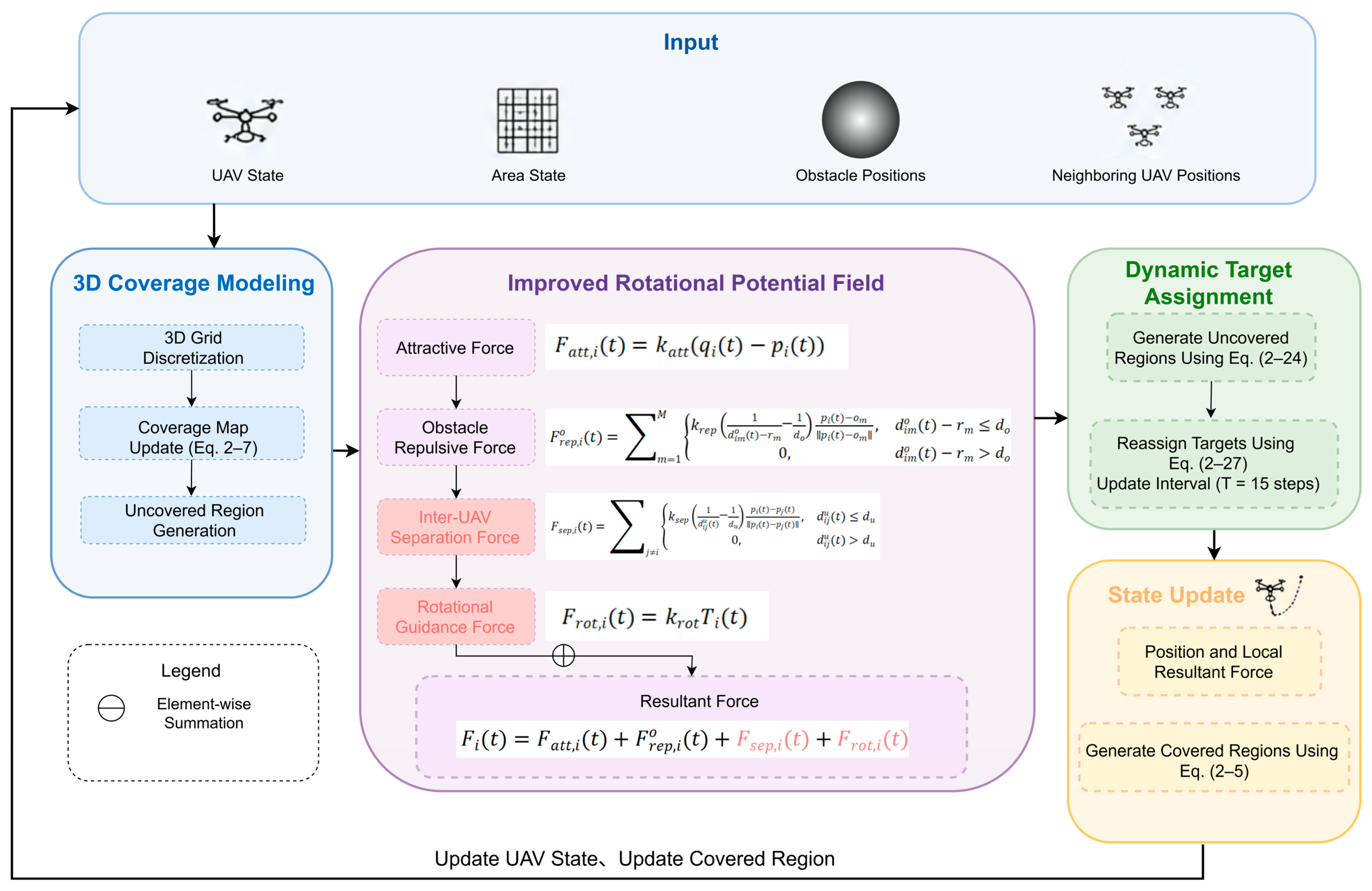
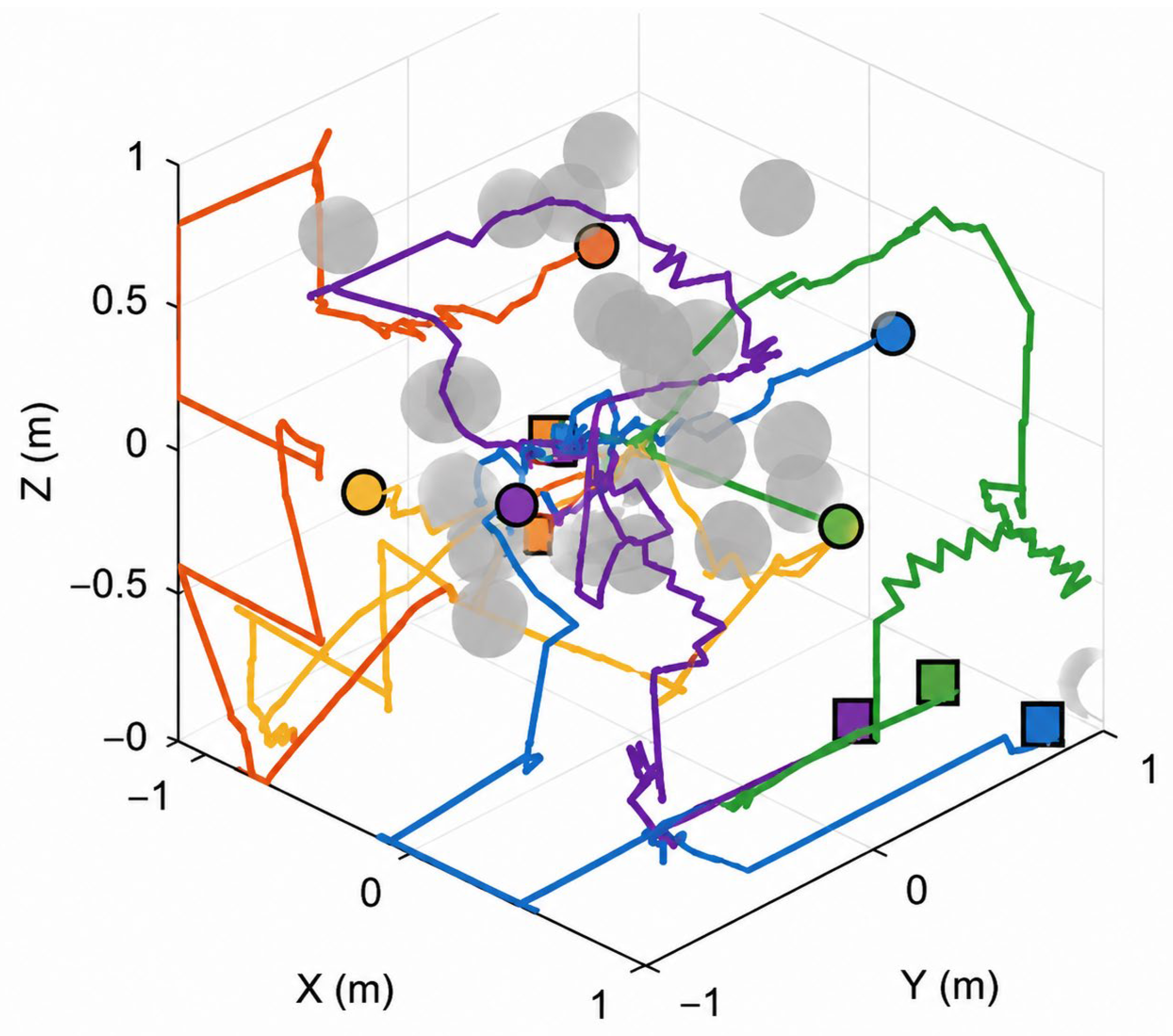
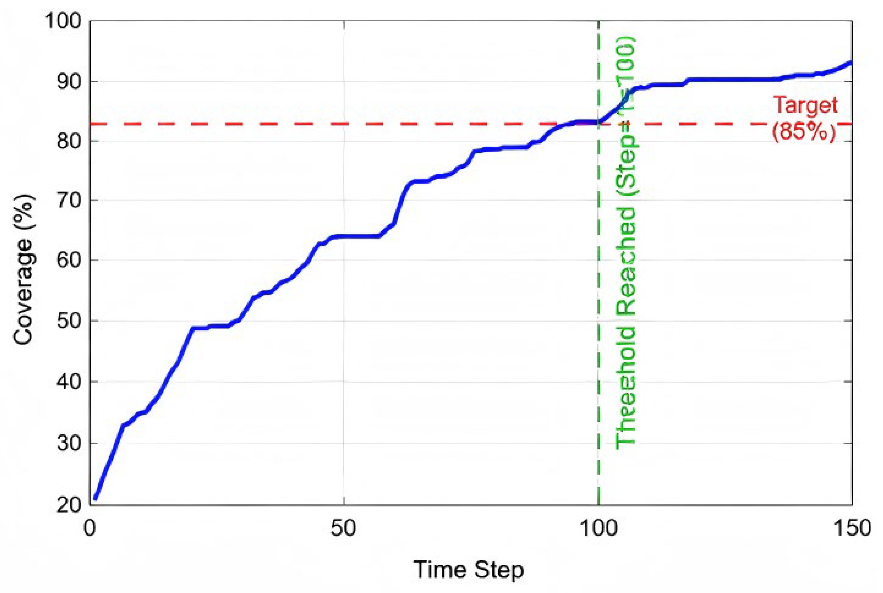
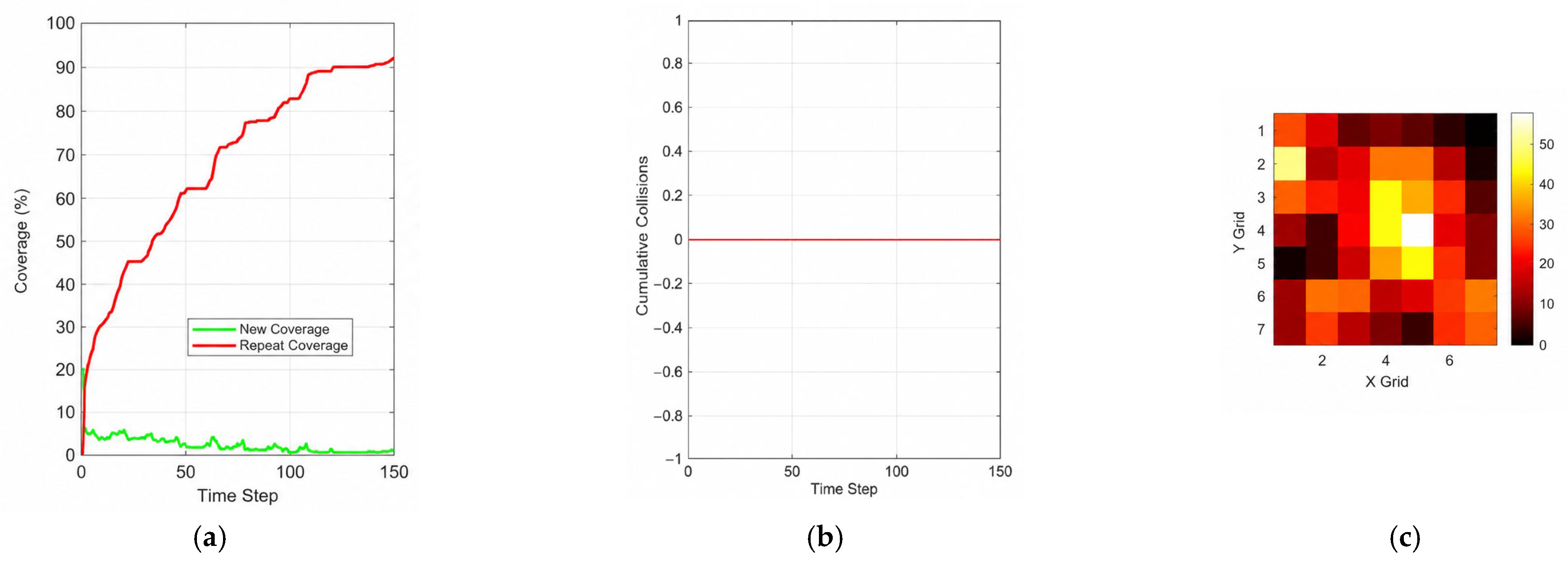
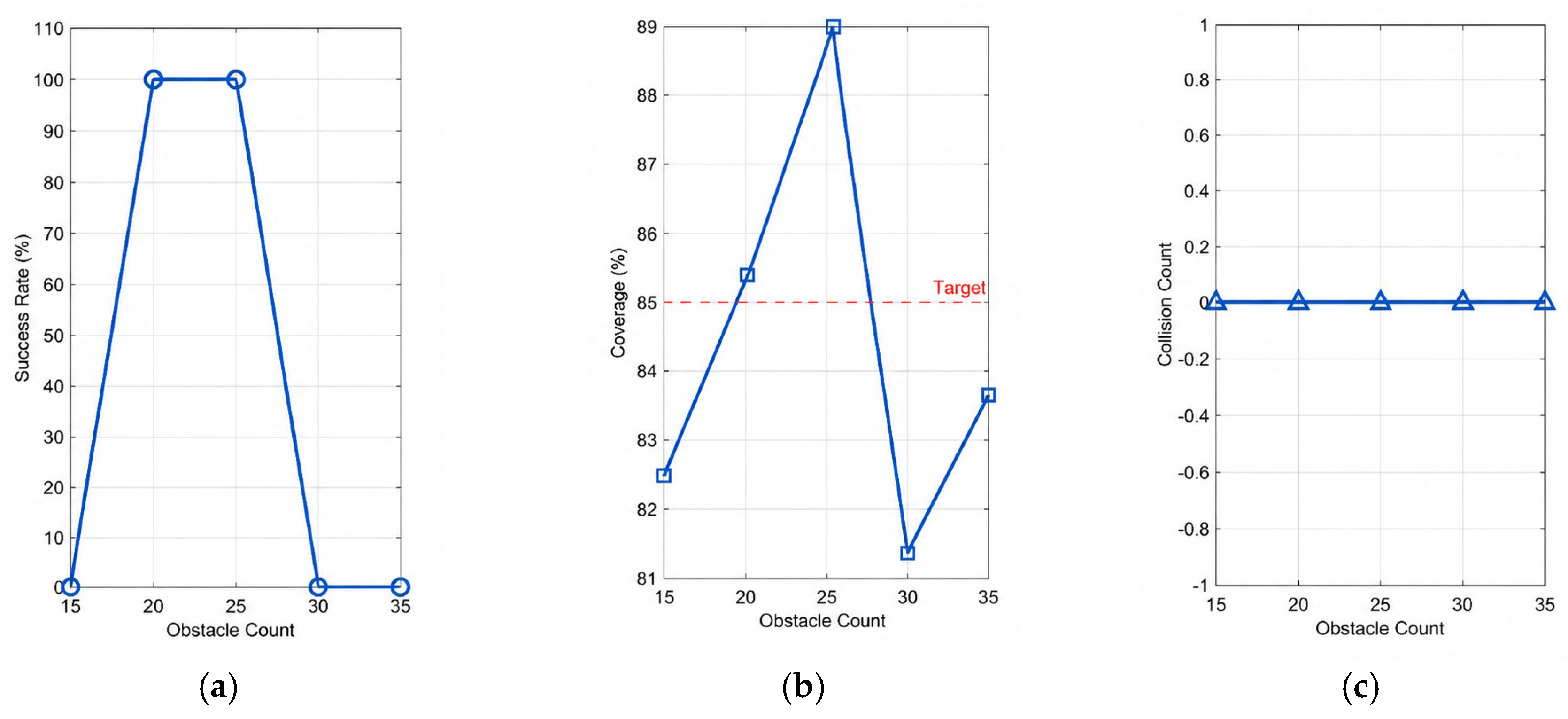
In this study, a multi-UAV cooperative exploration framework is developed for disaster remote sensing coverage tasks. The framework consists of three core modules: three-dimensional disaster area coverage modeling, improved rotational potential field-based path planning, and dynamic target assignment. First, dynamic environmental perception is achieved through three-dimensional grid modeling and coverage state updates. Then, the improved rotational potential field integrates attractive forces, obstacle repulsive forces, inter-UAV separation forces, and rotational guidance forces to generate safe motion strategies. Finally, the UAV target regions are dynamically adjusted based on coverage feedback results, enabling collaborative exploration and task optimization among multiple UAVs. The overall framework is illustrated in
Figure 3.
3.1. Three-Dimensional Remote Sensing Observation Area Coverage Modeling
In complex disaster environments, the primary objective of UAV remote sensing tasks is not to reach a fixed position but to maximize the information acquisition range of disaster areas within a limited time. Therefore, this paper models the disaster area as a three-dimensional remote sensing observation space and describes the UAV perception process of the target region through coverage states.
Let the disaster remote sensing observation space be defined as
. The observation area is divided into K regular three-dimensional perception grids. The grid set is represented as Equation (1):
Each grid cell represents a region to be observed.
denotes the (
)-th grid, and
represents the center position of the corresponding grid. Let
denote the cumulative observation frequency of the (
)-th grid at time (
). The coverage map can be expressed as Equation (2):
The system consists of
UAVs and
obstacles. The position, velocity, and local resultant force of the
-th UAV at time
are denoted as
,
, and
, respectively. Obstacles are approximated as spheres. The center position and radius of the
-th obstacle are denoted as
and
, respectively. The radius of the UAV body is defined as
. In this study, a first-order kinematic model is adopted to describe the UAV motion process, as shown in Equations (3)–(5):
where
represents the velocity scaling factor, and
denotes the discrete time step.
UAVs are equipped with remote sensing sensors. When the distance between any UAV and the center of the (
)-th grid is less than or equal to the sensing radius
, the corresponding region is considered to complete one remote sensing observation, as shown in Equation (6):
The real-time coverage rate is defined as Equation (7):
The final coverage rate is defined as Equation (8):
Let the coverage threshold be
. The time required to reach the coverage threshold is defined as Equation (9):
The repeated coverage rate is defined as Equation (10):
The coverage efficiency is defined as Equation (11):
These metrics evaluate coverage effectiveness, coverage speed, and redundant observations during the search process.
3.2. Multi-Uav Cooperative Coverage Model Based on the Improved Rotational Potential Field
Multi-UAV collaborative remote sensing information acquisition tasks in complex disaster environments are not traditional point-to-point navigation problems. Instead, they are collaborative coverage optimization problems for disaster spatial information acquisition. UAVs need to continuously observe disaster-affected areas using onboard sensors. They must ensure flight safety while maximizing effective remote sensing coverage. Therefore, this task is affected not only by environmental obstacles and UAV motion constraints but also by regional coverage efficiency, multi-UAV coordination, and dynamic observation requirements.
After establishing the three-dimensional remote sensing observation area coverage model, UAVs need to safely and continuously move toward uncovered local target regions in complex obstacle environments. For the (
)-th UAV, let
denote the local target position and
denote the current position. The attractive force generated by the target is defined as Equation (12):
Disaster areas often contain collapsed buildings, hazardous structures, and no-fly zones. Therefore, an obstacle constraint model is required. This paper uses obstacle repulsive forces to describe the spatial relationship between UAVs and hazardous areas. The model enables UAVs to avoid risk regions while maintaining continuous remote sensing coverage.
Let the distance between the (
)-th UAV and the center of the (
)-th obstacle be defined as Equation (13):
The obstacle repulsive force is defined as Equation (14):
Let the distance between the (
)-th UAV and the (
)-th UAV be defined as Equation (15):
During multi-UAV remote sensing coverage, excessively close flight can increase collision risks and cause observation overlap and resource waste. Therefore, an inter-UAV separation force is introduced to maintain safe distances and spatial coverage dispersion. The inter-UAV separation force is defined as Equation (16):
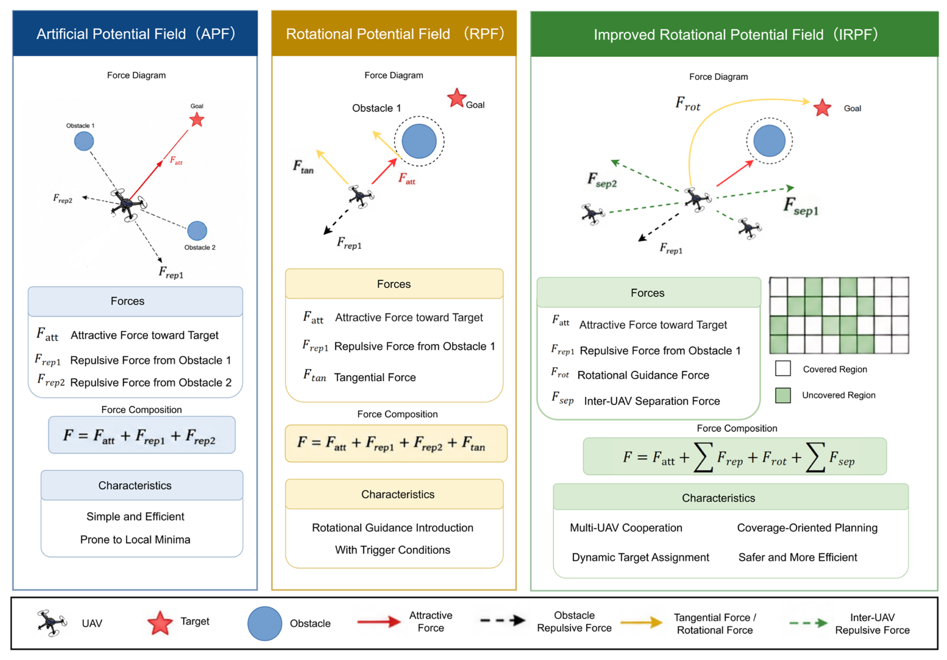
In disaster remote sensing environments, obstacles may interrupt observation paths and make it difficult for UAVs to maintain continuous information acquisition trajectories. APF methods may cause UAVs to become trapped near obstacle boundaries, which reduces remote sensing coverage efficiency. Therefore, this paper introduces a target-direction-constrained rotational guidance mechanism. It generates a horizontal lateral motion component and enables UAVs to maintain continuous observation trends during obstacle avoidance.
Let the unit vector of the target direction be defined as Equation (17):
The fixed rotational axis is defined as Equation (18):
The horizontal lateral unit vector is then defined as Equation (19):
The rotational guidance force is defined as Equation (20):
During the calculation of the rotational guidance vector, a singularity may occur when the target-direction vector is parallel or nearly parallel to the predefined vertical axis. In this case, the cross product used to construct the tangential direction approaches zero. To avoid numerical instability, the rotational direction is activated only when the cross-product magnitude exceeds a predefined threshold:
where
. Otherwise, the rotational force is set to zero, and the UAV continues navigation based on the other potential field components.
Therefore, the local resultant force acting on the (
)-th UAV at time
is defined as Equation (22):
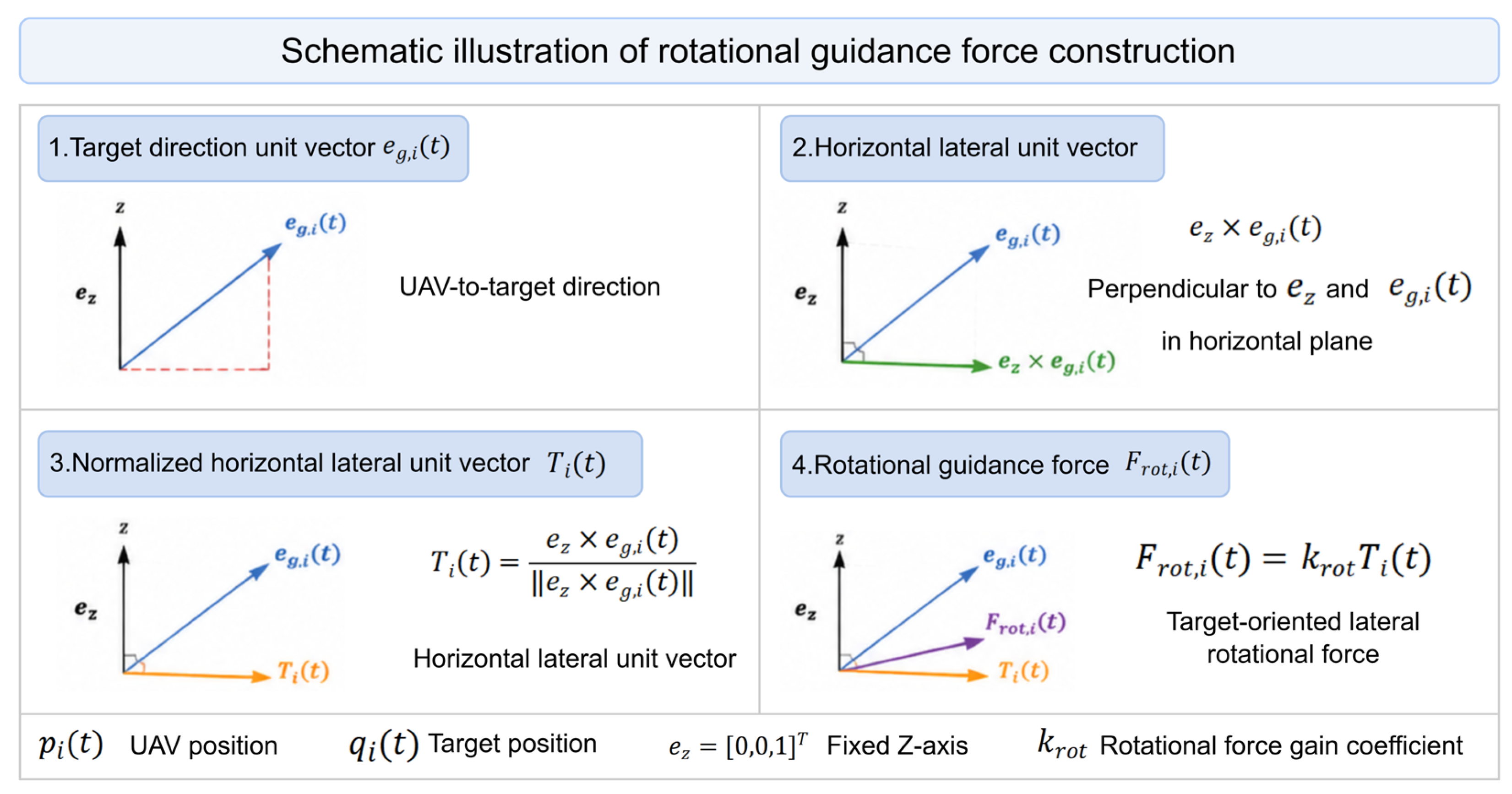
As shown in
Figure 4, the geometric construction process of the rotational guidance force is described as follows: First, the target direction unit vector
is constructed based on the spatial relationship between the UAV’s current position and the target position. This vector represents the desired movement direction from the UAV position toward the target region. Then, a fixed vertical axis vector is introduced. The horizontal lateral direction is obtained through the cross product of these two vectors. Since the cross product result is perpendicular to both the target direction vector and the fixed axis, the generated lateral unit vector
lies in the horizontal flight plane of the UAV. It provides a lateral motion component perpendicular to the target direction. Based on this mechanism, the rotational guidance force is obtained by adjusting the lateral guidance strength through the rotational gain coefficient
.
Unlike the tangential force in rotational potential field methods, where the rotational direction is determined by the obstacle repulsive force, the proposed method uses target direction information to determine the rotational guidance direction. Therefore, the rotational effect is no longer limited to obstacle boundary detouring. Instead, it maintains target-oriented constraints during the obstacle avoidance process.
In the proposed IRPF model, the rotational guidance force is not continuously applied during the entire flight process. It acts as an auxiliary component when obstacle constraints interfere with the UAV’s direct movement toward the target region. When the UAV moves in an obstacle-free environment or the target-oriented motion can be achieved by the attractive force, the influence of the rotational guidance component is minimized. During obstacle avoidance, the rotational guidance force provides a lateral motion component determined by the target direction, enabling the UAV to bypass obstacles while maintaining the overall movement trend toward uncovered regions. Unlike conventional rotational potential field methods, which mainly rely on obstacle boundaries to determine tangential directions, the proposed strategy avoids unnecessary lateral movements by constraining the rotational direction with target information.
To ensure system safety, this paper introduces two types of collision constraints: UAV–obstacle and UAV–UAV collision constraints, as defined in Equations (23) and (24).
3.3. Coverage Feedback-Driven Dynamic Target Assignment Mechanism
The improved rotational potential field model mainly addresses the safe motion problem of UAVs in local environments. However, for large-scale disaster areas, the dynamic assignment of multi-UAV remote sensing task targets also needs to be considered. Therefore, this paper generates dynamic observation targets based on real-time coverage states. This strategy enables UAVs to prioritize regions with incomplete information acquisition. The set of unobserved remote sensing regions at time (
) is defined in Equation (25):
For the (
)-th UAV, the local target is selected as the nearest grid center from the set of unobserved grids. The selection process is defined as Equations (26) and (27):
Considering that updating the local target at every step may cause frequent changes in the UAV motion direction, this study adopts a periodic target update strategy. Let the target update period be
. The update process is defined as Equation (28):
During dynamic target assignment, multiple UAVs may select identical or nearby uncovered regions due to similar distances. To avoid redundant task allocation, a conflict-resolution strategy is introduced. The target assignment is performed sequentially. After a target region is assigned to one UAV, this region is temporarily marked as occupied and excluded from the candidate target set for the remaining UAVs. If two UAVs have similar preferences for the same uncovered region, the UAV with the smaller target distance is assigned first, while the other UAV is redirected to the next nearest uncovered region. This mechanism ensures that different UAVs are encouraged to explore different regions and reduces unnecessary repeated coverage caused by conflicting target assignments.
This mechanism integrates real-time remote sensing coverage feedback with UAV task states. It maps the information deficiency distribution of disaster areas into dynamic observation requirements and enables adaptive task adjustment among multiple UAVs. Based on this mechanism, the improved rotational potential field model further incorporates environmental obstacle constraints and inter-UAV coordination relationships. It drives UAVs to move toward uncovered observation regions along safe and continuous trajectories. Finally, an autonomous cooperative remote sensing coverage process is established for disaster scenarios.