Article

Application of TRIZ Methodological Tools for Wearable Device Design Using Low-Cost Off-the-Shelf Sensors

by
Efrain Atenogenes Mejía-González
1,
Miguel Angel Castro-Perez
2,
Salvador Villarreal-Reyes
2,*,
Jesús Everardo Olguín-Tiznado
1,
Alejandro Galaviz-Mosqueda
3,
Claudia Camargo-Wilson
1,
Julio César Cano-Gutiérrez
1,
Jorge Luis García-Alcaraz
4 and
Cecilia Rodríguez-Serrato
1
1
Facultad de Ingeniería, Arquitectura y Diseño, Universidad Autónoma de Baja California, Ensenada 22860, BC, Mexico
2
Electronics and Telecommunications Department, Applied Physics Division, Centro de Investigación Científica y de Educación Superior de Ensenada, Baja California, (CICESE Research Center), Ensenada 22860, BC, Mexico
3
Monterrey Academic Unit, Centro de Investigación Científica y de Educación Superior de Ensenada, Baja California, (CICESE Research Center), Monterrey 66629, BC, Mexico
4
Department of Industrial and Manufacturing Engineering, Autonomous University of Ciudad Juarez, Ciudad Juárez 32310, CH, Mexico
*
Author to whom correspondence should be addressed.
Appl. Sci. 2026, 16(11), 5270; https://doi.org/10.3390/app16115270
Submission received: 23 March 2026 / Revised: 29 April 2026 / Accepted: 30 April 2026 / Published: 25 May 2026
(This article belongs to the Special Issue Wearable Devices: Design and Performance Evaluation)

Abstract

Currently, there is a widespread use of inertial motion units (IMUs) based on micromechanical systems (MEMS) with applications ranging from consumer electronics to medical devices. One of the main uses of this technology is in human body motion capture systems, which require attaching various IMUs to the body. It is customary to start the design of IMU-based motion capture solutions by using generic off-the-shelf (OTS) solutions or custom integrations. However, it is common that generic OTS solutions or custom IMUs integrations are not necessarily intended or designed to be directly attached to the human body. To address this issue, a widely adopted solution is to perform quick workarounds to enable the IMUs to be “worn” by prospective users. However, this can have the drawbacks of increased probability of detachment, improper fit, user discomfort, adding noise to the IMU measurements, etc. Therefore, the development of OTS IMU-based motion capture solutions would greatly benefit from having a methodological approach for the design of device housings and/or adaptations for OTS solutions or custom IMU integrations, such that they can be effectively used as wearable devices. In this work, we introduce a design methodology for wearable devices based on the Theory of Inventive Problem Solving (TRIZ). By designing a “wearable device housing” for an OTS IMU solution, we show that the proposed TRIZ-based methodology provides a straightforward and structured approach for the design of wearable devices. Furthermore, we illustrate how various challenges encountered in the early stages of prototype development can be effectively addressed using this methodology. The results obtained with the study case confirm that the proposed TRIZ-based methodology effectively overcomes the challenges associated with the design of wearable devices based on generic OTS solutions or custom IMU integrations.

1. Introduction

Human mobility impairments caused by injury, disease, aging, or neurological conditions often require prolonged physical rehabilitation to improve quality of life. Although effective rehabilitation ideally involves trained professionals in specialized centers, access to such services is limited in many regions, particularly in rural and low-resource settings [1,2]. Consequently, home-based physiotherapy has emerged as a practical alternative [3,4]. While this approach reduces travel and cost, it lacks professional supervision and objective feedback, increasing the risk of incorrect execution and reduced therapeutic effectiveness. To mitigate these limitations, sensor-based support systems have been proposed to monitor and evaluate physiotherapy exercises performed at home [5,6]. Particularly, the use of wireless inertial measurement units (IMUs) has been proposed to detect and evaluate body motion as an assisting tool in physical rehabilitation [7].
Commercial wearable IMU systems provide high accuracy [8,9] but remain costly [10,11] limiting their adoption in middle- and low-income contexts [12]. As a result, the use of generic off-the-shelf (OTS) wireless IMUs and low-cost custom integrations have gained attention as affordable alternatives [13]. However, many OTS solutions and custom IMU integrations (e.g., using breakout boards) were not originally designed to be “worn”, as they lack appropriate housing for secure, comfortable, and reliable attachment to the body. This has been commonly solved by using quick workarounds or adaptations to attach the IMUs to the body [14,15,16,17] without necessarily following a systematic approach for the design of the attachment mechanism. Poor attachment design can introduce motion artifacts, reduce user comfort, and ultimately hinder acceptance and usefulness [18]. A possible solution is designing custom housings that allow OTS solutions and custom IMU integrations to become wearables. This is not a trivial task, as designing effective wearable housings requires balancing mechanical stability, usability, comfort, and manufacturability. Note that these challenges are not easily addressed through unsystematic or traditional trial-and-error design approaches [19].
This paper proposes a methodology based on the Theory of Inventive Problem Solving (TRIZ) to systematically guide the transition from low-cost off-the-shelf (OTS) sensors to a wearable device solution. The proposed methodology employs TRIZ tools to identify and resolve design contradictions related to usability, ergonomics, mechanical stability, and wearability, enabling solutions beyond incremental or trial-and-error optimization. The methodology is demonstrated through the design of a wearable housing for the Texas Instruments SensorTag. The resulting design is then evaluated in terms of its “wearability” by real users. Although the application example focuses on housing design, the proposed methodology can be readily applied to address other challenges arising in wearable design.
The main contribution of this work is the formulation and validation of a TRIZ-based methodological approach for wearable design. The presented results show how low-cost OTS platforms can be adapted into functional wearables suitable for real-world use. Our aim is to provide a methodological tool to help designers and developers address challenges arising in wearable design, even from the early stages of prototype development.
The remainder of this paper is organized as follows: Section 2 presents the background reviews related to this work. Section 3 describes the proposed TRIZ-based methodology for designing wearable devices from OTS wireless IMU sensors. Section 4 reports the results obtained from the proposed design approach and its experimental evaluation. Section 5 provides a discussion of the findings and their implications for wearable device design. Finally, Section 6 concludes the paper and outlines directions for future work.

2. Background

TRIZ, developed by Genrich Altshuller in the 1940s, is a structured methodology for systematic problem solving and innovation in engineering. It was derived from the analysis of millions of patents, identifying universal principles to resolve technical contradictions without compromising essential functionalities. TRIZ provides tools such as the contradiction matrix, 40 inventive principles, and scientific effects, guiding designers toward innovative solutions [20,21,22,23,24,25].
Inventive problem-solving methodologies, including classical approaches such as Brainstorming [26,27], the Delphi method [28], and Synectics [29], often rely on intuition or trial-and-error. In contrast, TRIZ offers a systematic framework to identify and resolve technical contradictions, with proven success across engineering [30,31,32,33,34], transportation [35], occupational health [36], and biomedical engineering [37]. In biomedical applications, TRIZ is particularly effective for complex design challenges, enabling designers to balance ergonomics, usability, and technical performance, while minimizing subjective judgment [38,39].
TRIZ is well suited for wearable device design using OTS components. For example, by applying inventive principles such as “segmentation” or “nesting”, designers can address conflicts between device features, such as durability and flexibility. Thus, TRIZ provides tools to address key technical contradictions, like miniaturization, energy efficiency, and ergonomics, without compromising device functionality.
In general, we can summarize the process of applying TRIZ to an inventive problem as follows:
  • Analysis of the technical system: This is the first step; it involves breaking down the technical system into its components and functions. The system’s behavior, problems, and current limitations are analyzed.
  • Technical contradiction identification: This step involves identifying the technical contradictions, which are situations where improving one characteristic of the system leads to the worsening of another. According to TRIZ, resolving these contradictions is key to innovation and the methodology provides specific tools to address them.
  • Inventive principles: Here, the 40 inventive principles of TRIZ are applied to resolve the identified technical contradictions. Each principle offers a possible strategy for overcoming the problems without compromising other aspects of the system. These principles are designed to inspire innovative and out-of-the-box solutions.
  • Development of a conceptual solution: In this step, the selected inventive principles are used to generate a conceptual solution that addresses the identified problem. Initial models or prototypes of the solution are developed. This is a critical step in the methodology, as it translates the abstract ideas of the principles into a specific and concrete design.
We refer the reader to reference [40] for a full description of TRIZ methodology.
As mentioned in the introduction, in the literature it is common to find quick workarounds and customizations to provide generic OTS IMUs solutions with some degree of wearability. For example, in [14], it can be seen that the IMU was attached to the body using Velcro straps. In [15], the SensorTag was attached to the front of the diaper using a type of adhesive bandage. The previously mentioned works have in common their focus on rapid prototyping to provide wearability, but seldom incorporate structured problem-solving methods. Thus, in this contribution we introduce a TRIZ-based inventive methodology to guide the transition from generic OTS wireless IMUs to a wearable device in a systematic way.

3. Using TRIZ to Design a Wearable Device Based on a Generic Off-the-Shelf Wireless IMU Solution

In this work, we propose the TRIZ-based methodology shown in Figure 1 for designing a wearable device based on a generic OTS (or custom integration) wireless IMU solution.
Figure 1 outlines the application of the proposed TRIZ-based methodology, structured into six sequential steps:
  • Identification of the generic device: This step involves selecting the generic device, which serves as the baseline for the subsequent analysis.
  • Designer/user requirements analysis: A thorough analysis of both the designer’s specifications and the end-user’s needs are conducted to establish the functional and technical requirements of the device.
  • Application of TRIZ principles: TRIZ inventive principles are applied to address the identified contradictions, proposing innovative solutions to optimize device performance.
  • Prototype and proof of concept: A prototype is developed based on the TRIZ-derived solutions, and proof-of-concept testing is conducted to validate the feasibility and functionality of the proposed design.
  • Final user evaluation: The prototype undergoes user testing, and feedback is collected to refine and optimize the design, ensuring it meets user expectations and performance requirements.
  • Final wearable device presentation: The final iteration of the wearable device for deployment or further development.
Next, we will explain how each of the blocks shown in Figure 1 were implemented and executed in the design of a housing for the SensorTag with the aim of obtaining a wearable device.

3.1. Identification of the Generic Device

To present our proposed methodology, we have chosen the SensorTag from Texas Instrument, as it has been widely used for motion analysis research [41,42,43,44]. However, the size and form factor of the SensorTag present a challenge to be straightforwardly used as a wearable device, which makes it a good study case for the development of a housing that allows the SensorTag to become wearable.
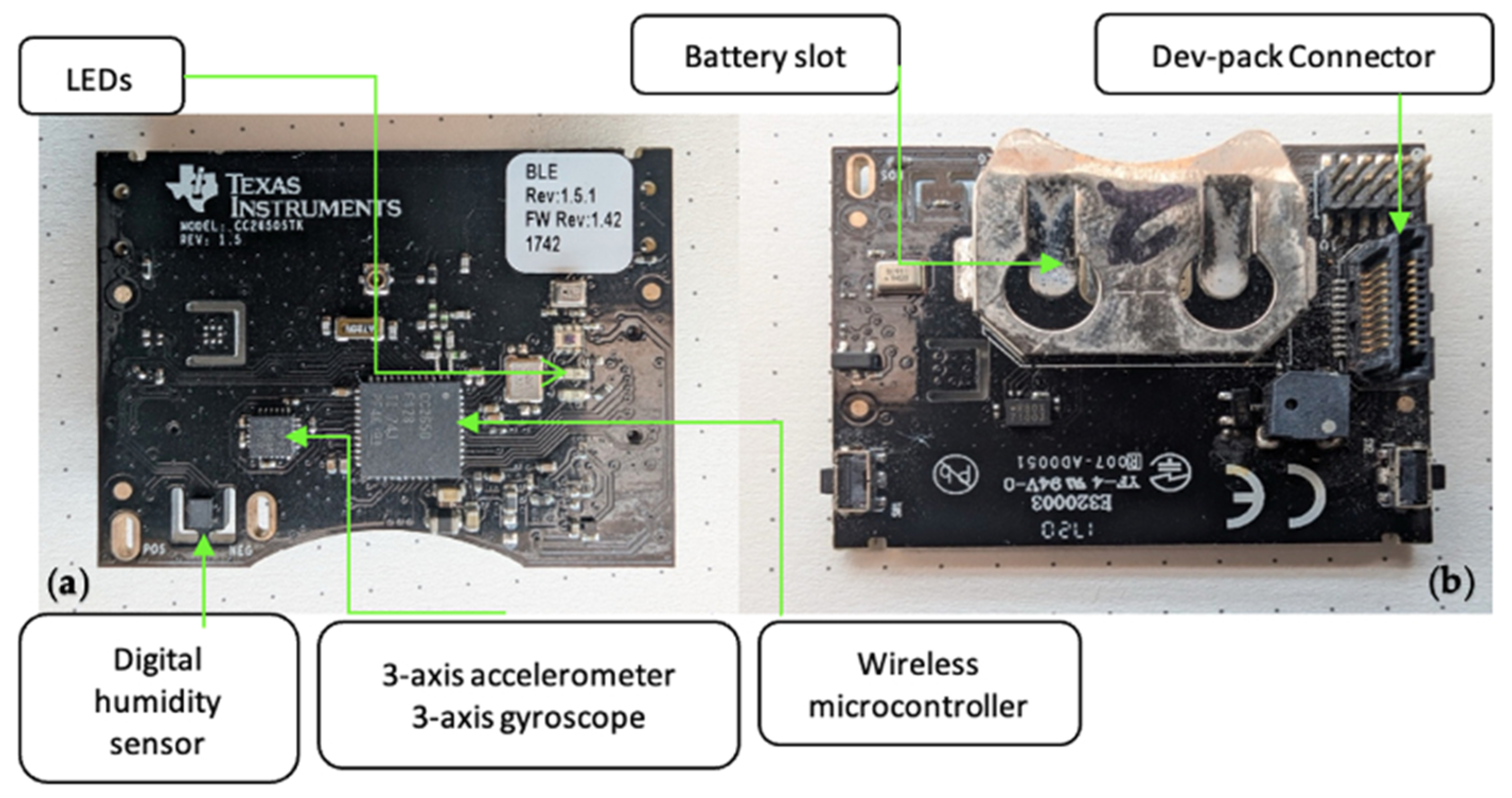
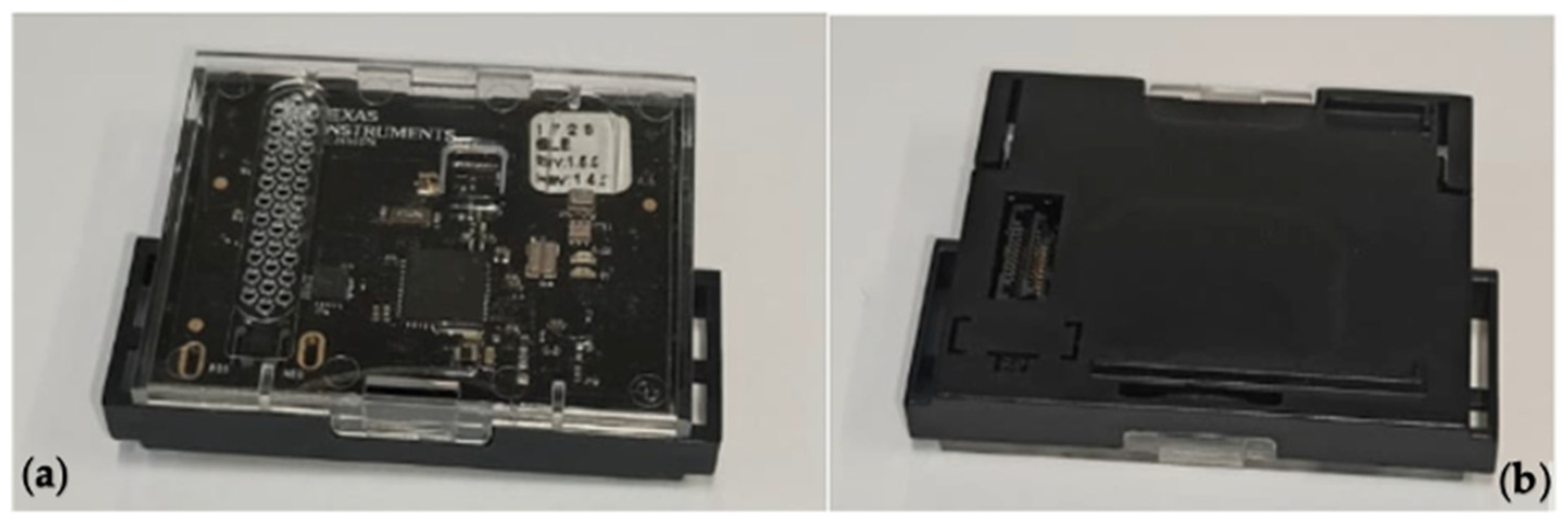
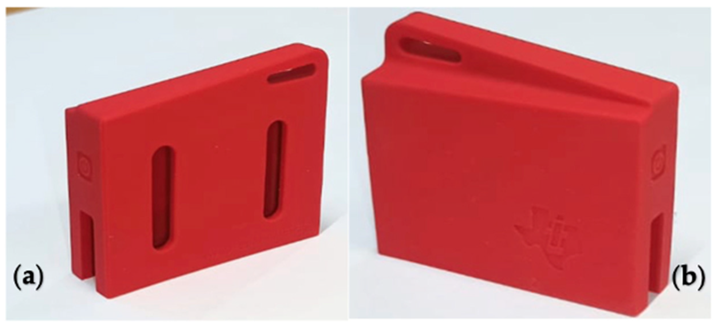
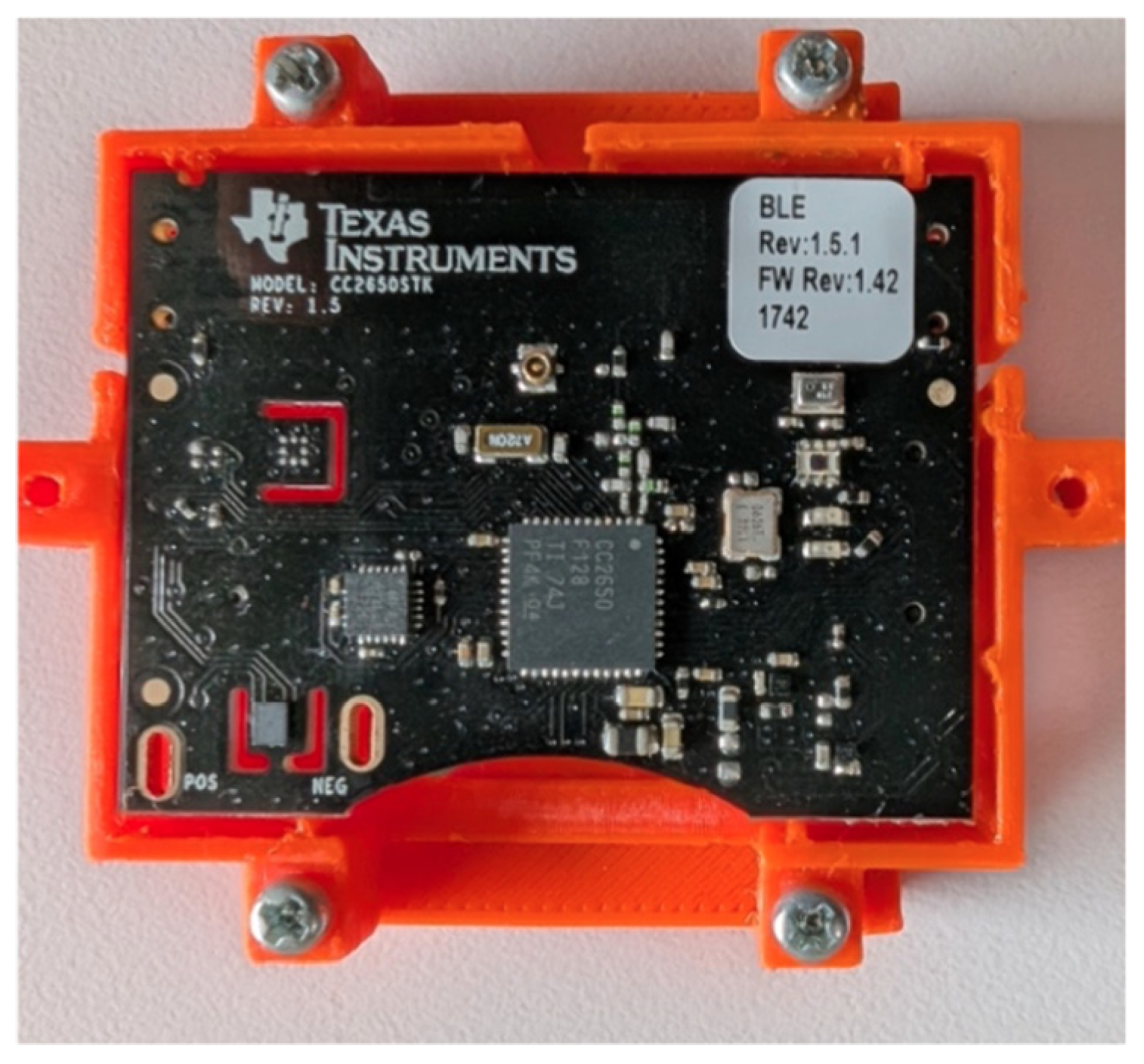
The SensorTag is a compact platform that integrates multiple sensors, including accelerometers, gyroscopes, magnetometers, and environmental sensors for temperature, pressure, and ambient light. It connects wirelessly via BLE or Zigbee, enabling real-time data collection for applications in biomechanics, physical activity monitoring, and IOT research [45,46,47,48]. Figure 2 shows the SensorTag, highlighting its main characteristics in the (a) front and (b) back views. In addition, Texas Instruments provides a general-purpose device housing and sleeve for the SensorTag, as shown in Figure 3 and Figure 4.

3.2. Designer/User Requirements Analysis

Once the OTS device used in our study case has been introduced, we must perform designer/user requirements analysis. For the SensorTag, we started by analyzing its commercially available housing shown in Figure 3. This is the primary option for protecting the sensor and has the following identifiable characteristics:
  • It is made of two pieces of rigid plastic, one of them transparent.
  • Allows visibility of the SensorTag and its operational LEDs.
  • Access to the Devpack expansion connector.
  • It has openings to allow proper operation of sensors like humidity.
  • It is necessary to open the case and remove the SensorTag to replace the battery.
  • Its main function is to protect the sensor and it was not designed to allow the SensorTag to be used as a wearable device.
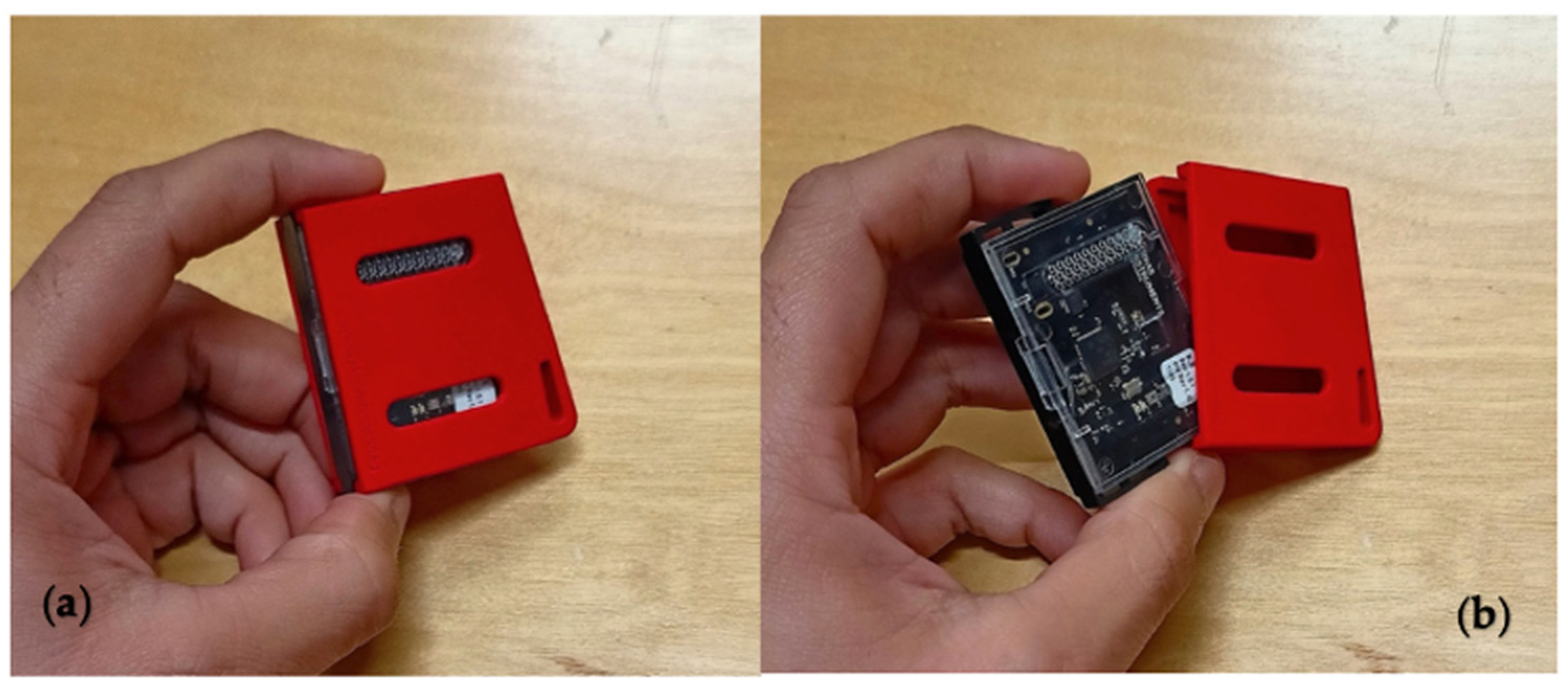
Besides the rigid plastic housing, there is a commercially available sleeve shown in Figure 4. This sleeve must be used together with the housing, forming an assembled enclosure (as shown in Figure 5), and has the following identifiable characteristics:
(1)
It is made of a flexible rubber-like material.
(2)
The rigid housing containing the SensorTag must be inserted in the sleeve providing an additional layer of protection.
(3)
Allows visibility of the SensorTag and its operation LEDS.
(4)
The Devpack expansion connector becomes fully enclosed and is not readily accessible when using the sleeve.
(5)
It has openings to allow proper operation of sensors like humidity.
(6)
It increases the complexity of the battery replacement procedure.
(7)
The sleeve does not provide any mechanism to avoid non-intended slippage or removal of the plastic housing.
Note that the SensorTag, its housing, and sleeve were not originally designed to collect data by being directly worn by the user.
As previously mentioned, it is customary to apply quick workaround customizations to provide some wearability to generic OTS IMU solutions (e.g., see [14,15,16,17]). Thus, for our study case, we considered two straightforward adaptations commonly implemented in research that does not focus on the usability aspects of wearable device design. The analysis of these adaptations is the starting point to exemplify the application of the methodological approach for the wearable design proposed in this paper.
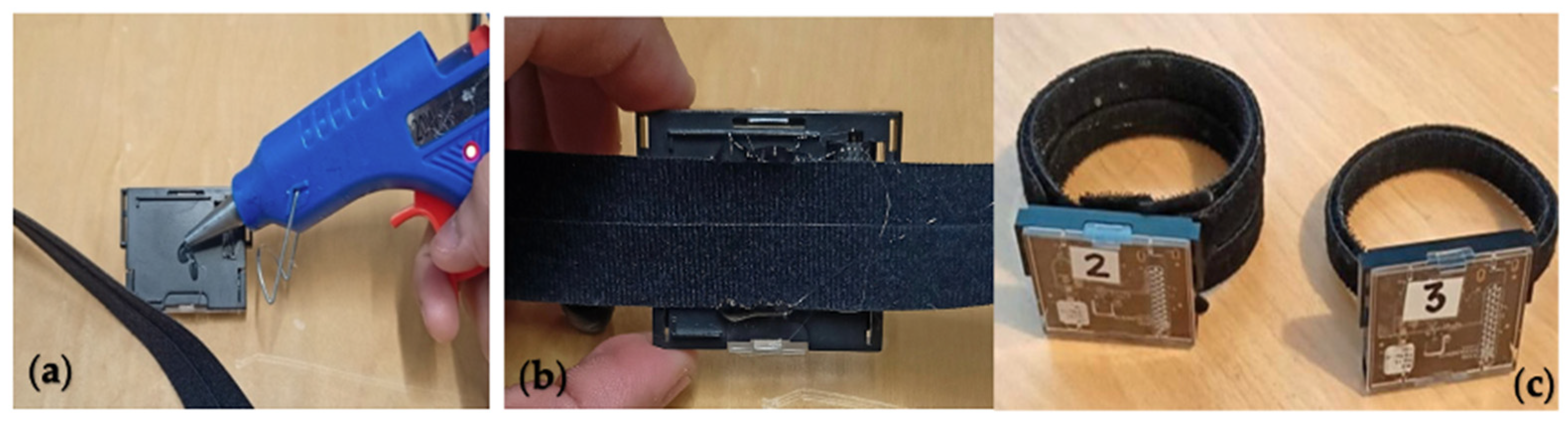
The first adaptation analyzed in this study consisted of gluing Velcro straps to the rigid plastic housing, as shown in Figure 6.
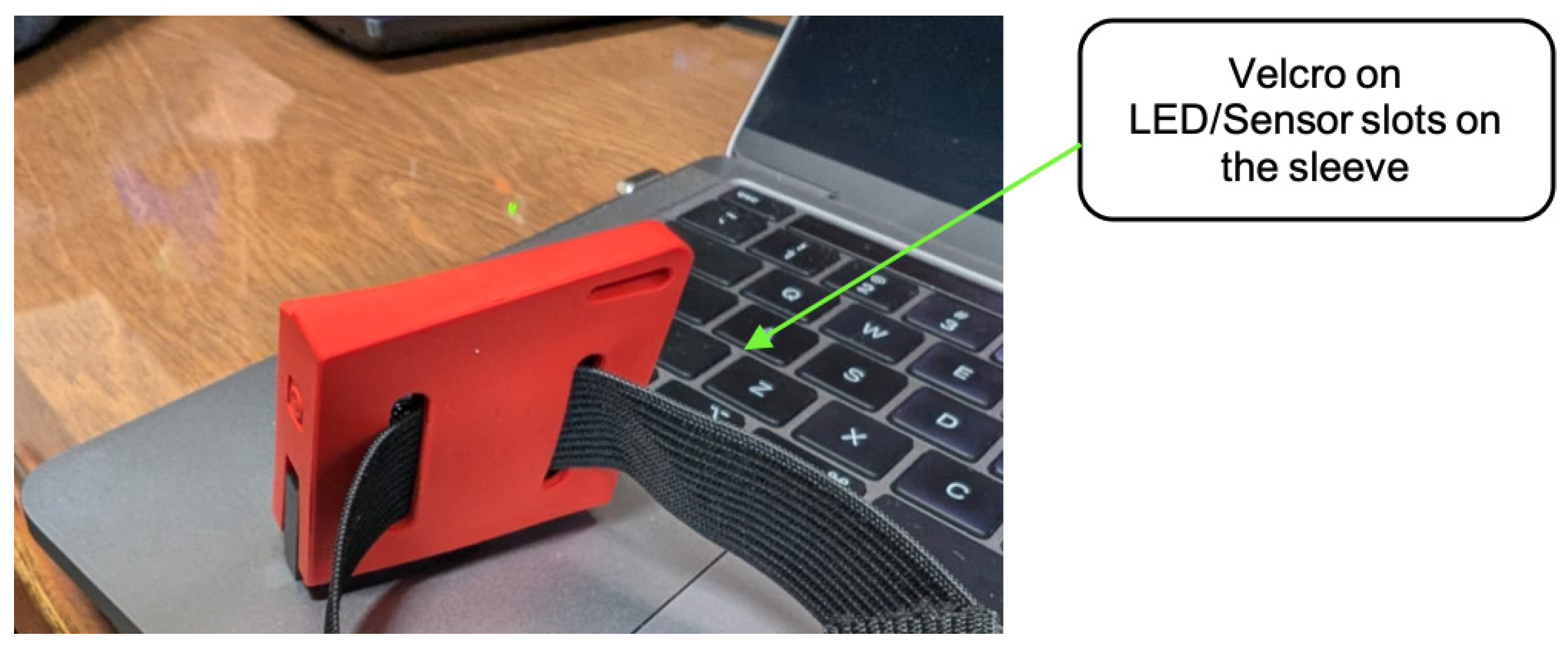
The second adaptation consisted of using the long openings in the sleeve to pass a Velcro strip through them, as shown in Figure 7. This resulted in two quick and simple workarounds that provided the SensorTag with some degree of wearability. It is important to mention that these adaptations were originally performed within another research effort focusing on the development of artificial intelligence solutions for movement classification. Thus, they were not performed as part of an iterative approach for the design of wearable devices.
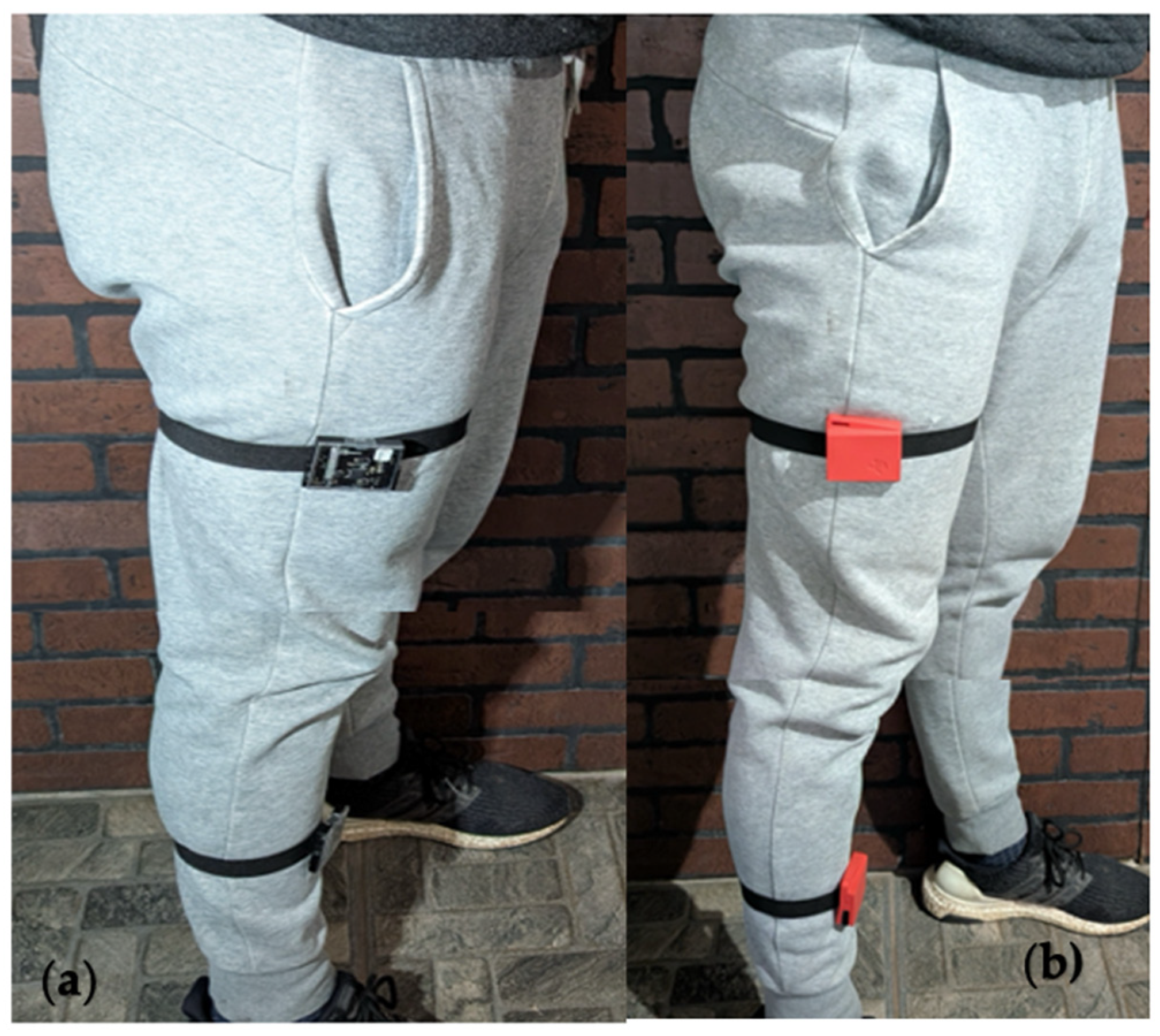
As shown in Figure 8, in our study case two sensors are required in the specified positions for sample collection. Using the previously described adaptations to capture signals during trials, we were able to identify key user requirements for the wearable device. Examples of the challenges to be addressed include user discomfort, design constraints during device attachment, ease of adjustment between extremities, and signal capture issues caused by loose fittings, among others. By identifying these challenges and engaging with users, we were able to define the following designer requirements, as outlined below:
  • The device must have a fastening mechanism that securely attaches it to the user’s leg.
  • The device housing and the fastening mechanism must ensure that the sensor’s position is maintained despite user movement.
  • The device must include a dedicated access point for efficient battery extraction.
  • The strip of the fastening mechanism should accommodate muscle contraction.
  • The device housing must restrict children’s access to the sensor.
  • The fit between the SensorTag and the housing must be tight, such that internal bouncing of the SensorTag within the housing is non-existent.
  • The designed device housing must provide additional protection compared to the commercial housing.
  • The strap of the fastening mechanism must be comfortable for the user (avoiding uncomfortable tension caused when using Velcro).
  • The strap must allow for adjusting the diameter for different extremities.
  • Once attached, the device must allow visibility of the operational LEDs.
Once the user requirements have been identified, we can apply the proposed TRIZ framework for the design of a device housing adequate for the use of the SensorTag as a wearable device.
Within the framework of the research reported in this contribution, the adaptations were analyzed as an exploratory step to systematically elicit user needs and identify technical contradictions. The observations derived from these adaptations served exclusively as inputs for the subsequent application of the TRIZ framework, ensuring that the final design decisions were guided by systematic contradiction resolution rather than empirical trial-and-error. Thus, the design decisions presented in the following stages were guided from the outset by the systematic identification of technical contradictions and their resolution through TRIZ tools, rather than by incremental empirical optimization.

3.3. Application of TRIZ Principles

Now we introduce the TRIZ principles that can be applied to design a device housing that provides the SensorTag with the functionality expected from a wearable device.

3.3.1. Identification of the Technical System and Problem Definition

The first step of the TRIZ methodology involves identifying and describing the technical system and its subsystems with a detailed account of their components and functions. This must be performed by using a systematic approach that allows the identification of features that can be improved, added or eliminated. A way to do this is by using tables and/or spreadsheets where the identified features are properly described, as shown in Section 4.1 where identification of the technical system and problem definition for the study case are performed.

3.3.2. Contradiction Analysis

A technical contradiction becomes evident when improving one characteristic/functionality of the system negatively affects another characteristic/functionality. This inherently leads to a contradiction.
An important step of the TRIZ methodology is to “translate” these contradictions into the TRIZ language using different predefined parameters. TRIZ considers 39 parameters that describe specific characteristics of the system or process under analysis. These parameters are used to analyze and classify contradictions, enabling designers to apply TRIZ solution principles more effectively and find creative solutions to complex problems. Some of the most common parameters include the following:
  • Weight of the object.
  • Size, volume, or area.
  • Speed.
  • Force.
  • Temperature.
  • Stress, strain.
  • Durability, Reliability.
  • Precision.
  • Complexity.
  • Time of action or process.
As in the previous step, to address contradiction identification in a systematic way it is recommended to use a predefined format in the form of tables or spreadsheets. The particular format used for our study case is presented in Section 4.2.

3.3.3. Application of TRIZ Inventive Principles

The TRIZ methodology considers 40 inventive principles that are strategies designed to resolve technical contradictions and foster creativity in problem solving. To identify which inventive principles are applicable to solve a contradiction, TRIZ considers the use of a contradiction matrix. In this matrix the parameters enlisted in the first column correspond to the parameters to be improved, while the parameters enlisted in the first row correspond to those that are deteriorated by the proposed improvement. It is at the intersection between rows and columns where the inventive principles suggested by TRIZ are provided. These principles are key tools in the TRIZ methodology, used to generate innovative solutions by addressing contradictions and challenges in design and engineering. Some of the most common principles include [49] division, combination, universality, asymmetry, counterweight, preliminary action, dynamic systems, use of fluids, range of variability, and transforming harm into benefit.
Several simplified approaches derived from TRIZ have been proposed to reduce methodological complexity:
  • Advanced Systematic Inventive Thinking (ASIT) is based on a closed world assumption, which restricts the solution space to existing system components and explicitly avoids the introduction of new elements. It employs five transformation operators (unification, multiplication, division, removal, and breaking symmetry) to generate solutions through internal modifications of the system. This approach does not explicitly incorporate contradiction modeling or parameter-based mapping between problems and solution strategies [50].
  • Unified Structured Inventive Thinking (USIT) provides a unified problem-solving framework that replaces the classical TRIZ knowledge base (e.g., contradiction matrix and the 40 inventive principles) with a structured process based on object–attribute–function analysis. It emphasizes detailed problem definition and employs a reduced set of solution operators (typically five), combined with systematic solution generation procedures. Unlike classical TRIZ, it does not rely on predefined inventive principles nor on formal contradiction mapping [51].
  • TRIZ 10 is a heuristic simplification that reduces the original set of 40 inventive principles to a smaller subset of frequently used strategies (e.g., segmentation, dynamization, and local quality). This approach facilitates rapid idea generation but does not provide a structured problem-solving process or a formal mechanism for linking specific contradictions to solution principles [52].
In this context, the use of the contradiction matrix was preferred over alternative approaches, including simplified subsets of principles (e.g., TRIZ-10) and methodologies such as USIT and ASIT, as it provides an explicit and reproducible link between the identified engineering contradictions and the suggested inventive principles (see Table S4 in the Supplementary Materials). This traceability is particularly important in this work, where the objective is not only to obtain a design solution, but to ensure methodological traceability between problem definition and design outcome. While alternative approaches such as ASIT or simplified subsets of principles (e.g., TRIZ-10) can be effective for guiding ideation, they do not explicitly preserve the direct linkage between specific technical contradictions and the resulting solution strategies. In contrast, the contradiction matrix provides a structured mapping between defined engineering conflicts and a bounded set of candidate inventive principles. This characteristic is particularly relevant in the present work, where the objective is not only to generate solutions but to ensure that each design decision can be traced back to a formally defined contradiction. Furthermore, the contradiction matrix has been widely used in engineering design to systematically translate functional conflicts into solution strategies, demonstrating consistent applicability across diverse engineering domains [30,31,32,33,34,35,36]. Its use enables a clear and traceable mapping between problem definition and solution generation, which is especially relevant in the design of wearable devices, where multiple functional requirements (e.g., adaptability, reliability, and usability) must be simultaneously addressed [37,38,39].
In this work, the selection of technical parameters was performed by analyzing the functional effects of each proposed solution and aligning them with the definitions provided in the TRIZ framework. Specifically, for each contradiction, one parameter was identified as the feature to be improved, and another as the feature negatively affected. These parameters were then used to query the contradiction matrix in a consistent and traceable manner.
Examples of the identification and application of TRIZ inventive principles for our study case are provided in Section 4.3.

3.3.4. Solution Generation

The inventive principles are tools derived from the application of the TRIZ methodology. These principles offer generalized solutions, which must be tailored to address specific technical contradictions identified in a given case. Consequently, the process involves selecting the most appropriate principle based on a literature review and applying it to the particular problem at hand. In our study case, this involves translating the suggested inventive principles to guidelines for the design of a wearable solution as explained in Section 4.3.

3.4. Prototyping and Proof of Concept

Prototyping involves creating a preliminary version, either physical or digital, of a product, system, or idea. This is done to test the proposed solution’s functionality, design, and feasibility before manufacturing or implementing it on a large scale. It is a key process in solution development, because it allows identifying problems, validating concepts, and adjusting at a lower cost and in less time.
Accordingly, the prototype represents the materialization of a conceptual solution derived from selected TRIZ inventive principles and is not the result of iterative trial-and-error adjustments.
For our study case a device housing design was obtained after applying the proposed methodology, which then was used to 3D-print a proof-of-concept prototype for our study case, as explained in Section 4.4.

3.5. Final User Evaluation

The user evaluation of the proof-of-concept prototype is crucial, as it helps to validate whether the design meets the real needs and expectations of the users. This evaluation provides valuable feedback on the prototype’s functionality, usability, and comfort, identifying potential improvements before mass production. By involving the final user, a higher level of confidence that the product is effective and fulfills the intended objectives can be achieved, thereby increasing its chances of success.

Recruitment and Ethical Considerations

For our study case, user evaluation was performed by recruiting 153 volunteers that were asked to wear the resulting solution and perform some typical rehabilitation exercises. The recruitment of participants and data collection through questionnaires began on 10 July 2025 and ended on 18 August 2025. All participants provided written informed consent prior to their inclusion in the study, which is in accordance with the ethical guidelines approved by the Bioethics Committee of CICESE.
An initial questionnaire with 31 questions was developed to evaluate the user satisfaction and efficacy of the proposed solution. The results of this evaluation are presented in Section 4.5.

3.6. Final Wearable Device Presentation

After prototyping, if the results are positive, the designer can move forward with the final presentation of the wearable device. This stage involves refining the design based on feedback and ensuring the product meets all designer/user requirements. The final presentation includes showcasing the device’s capabilities, usability, and how it addresses the initial objectives. It also provides an opportunity to demonstrate its potential impact on the target users and gather further feedback for any final adjustments before mass production.
In our study case we did not perform this step as the goal of this contribution is not to pursue mass production of the wearable device, but to introduce a methodology that can be effectively used by designers of IMU-based solutions to systematically address issues arising in the early stages of wearable device development.

4. Results

Continuing with the development of the study case, the results of applying the proposed methodology for the development of a wearable device housing for the SensorTag are provided next.

4.1. Identification of the Technical System and Problem Definition

For our study case, we consider that the technical system consists of the SensorTag altogether with the quick workaround customizations performed to provide the commercial housing with a fastening solution.
Table 1 presents the identification of the technical system, which includes its name, primary objective, main elements and functions, and operation description. Additionally, it outlines the problems associated with the system—specifically, the characteristics that require improvement or elimination. These identified problems serve as the basis for formulating technical contradictions.

4.2. Contradiction Analysis

Using the results provided in Table 1, we can proceed with contradiction analysis. A technical contradiction arises when a change in one variable of a system improves one parameter/function but adversely affects other features, parameters or functions. In other words, you cannot improve one feature of a system without negatively affecting another.
As an example of a contradiction, consider the Velcro strip added to the sleeve of the commercial housing (see Figure 6). This addresses the need to provide a fastening mechanism for the SensorTag. However, this solution modifies the form factor of the sleeve, worsens the fit between the sleeve and the rigid plastic case, increases the probability of slippage of the plastic case containing the SensorTag, increases the probability of unintended damage of the SensorTag (caused by probable drops), and inhibits visibility of the operational LEDs (needed to verify the functional status of the SensorTag). Therefore, the Velcro solution leads to a contradiction.
To address contradiction identification in a systematic way, a format like the one provided in Table 2 can be used (which was adapted from [53]). The data in this table allows us to formulate the contradiction arising when adding a Velcro strip to the sleeve of the commercial housing. Thus, Contradiction 1 (C1) is provided in the last row of Table 2 as follows:
C1.
If the feature of “adding a fastening mechanism” is addressed by “placing Velcro in the long openings of the sleeve”, then the following features, “fit between the sleeve and the rigid plastic case, probability of slippage of the plastic case containing the SensorTag”, become worse. The contradiction reveals itself.
In our study case C1 was not the only contradiction formulated, as more than 20 contradictions were identified. As our goal is to show the application of our proposed methodology, without loss of generality and for the sake of clarity and conciseness, the full list of contradictions and its respective tables are not included in the rest of the paper. Therefore, in the subsequent discussion we exemplify the use of the proposed methodology considering C1 and the following contradictions:
C2.
If the feature of “the device housing does not consider a fastening mechanism” is addressed by “glue a Velcro strip with hot silicone on the back of the rigid plastic housing”, then the following feature, “probability of accidental damage of the SensorTag caused by falls”, becomes worse (as the housing–Velcro bond is not durable) The contradiction reveals itself.
C3.
If the feature of “improving the ease of battery replacement” is addressed by “making the device housing easier to remove or modify (for example modifying the housings by cutting and/or drilling)”, then the following feature, “the protection of the sensor”, becomes worse. The contradiction reveals itself.
C4.
If the feature of “maintain the integrity of the sensor by preventing direct handling” is addressed by “establish explicit handling restrictions for the user in order to maintain its integrity”, then the following feature, “ease of use”, becomes worse. The contradiction reveals itself.
C5.
If the feature “of facilitating the contrast of movements when using video recording” is addressed by “using the commercial red sleeve”, then the following feature, “functionality of the device housing”, becomes worse. The contradiction reveals itself.

4.3. Inventive Principles

Once the technical parameters have been identified and the contradictions formulated, the inventive principles defined by TRIZ must be applied. As mentioned in Section 3.3.3, in our methodology we use a technical contradictions matrix. In this matrix the first column provides the technical parameters we want to improve, and the first row provides the technical parameters that are negatively affected by a proposed solution. The matrix considers 39 different standard technical parameters in both rows and columns. The cells in the matrix are filled with the numbers corresponding to the inventive principles (possible solutions) suggested by the TRIZ methodology. There are a total of 40 inventive principles that are provided as an enumerated list. We refer the reader to consult the full technical contradictions matrix and inventive principles provided by TRIZ, e.g., [54,55].
Translating the technical parameters and contradictions into TRIZ parameters is not a trivial task, but rather a key abstraction process that enables the systematic use of the contradiction matrix. For example, in C1 the addition of a Velcro strip enables the commercial housing to be attached to different body segments, effectively transforming it into a wearable device. This improvement corresponds to parameter “#35 Adaptability” in TRIZ, which refers to the ability of a system to adjust to different conditions or use scenarios. However, integrating the Velcro strip into the sleeve introduces deformation and compromises the fit between the sleeve and the rigid plastic housing. This increases the likelihood of unintended detachment of the SensorTag during use. Such behavior is associated with a loss of system dependability, which corresponds to parameter “#27 Reliability” in TRIZ, defined as the ability of a system to perform its intended function without failure. Alternative parameter mappings (e.g., stability or ease of use) were initially considered as well, but after analyzing its suitability were deemed less representative of the core functional contradiction. Note that this mapping establishes a clear relationship between the identified technical parameters and the abstract TRIZ parameters, enabling a consistent and traceable application of the contradiction matrix.
Continuing with the example for C1, in the contradiction matrix we must look for the cell corresponding to the parameter to be improved in the first column, which as previously mentioned is “#35 Adaptability”. Similarly, in the first row we must look for the cell corresponding to the parameter negatively affected, namely “#27 Reliability”. The intersection of the row and column corresponding to these parameters yields the TRIZ inventive principles #11, #10, #1, #16, as shown in Table 3. Once the inventive principles have been identified, the designer must consult the full description of each principle as provided by TRIZ, see [56,57]. Particularly, for this case the contradiction matrix recommends the following inventive principles:
  • #11 Cavitation;
  • #10 Preliminary action;
  • #1 Segmentation;
  • #16 Partial or excessive actions.
Principles such as “#11 Cavitation” and “#10 Preliminary action” were deemed of limited applicability for our study case. This is because they typically pertain to fluid dynamics or temporal sequencing and therefore cannot be used to resolve the structural contradiction between the fastening function and sleeve deformation. Similarly, the principle “#16 Partial or excessive actions” does not explicitly address the functional interference between components. In contrast, principle “#1 Segmentation” directly targets the root contradiction, by proposing the separation of conflicting functions into independent components. This aligns precisely with the identified contradiction, wherein integrating the fastening function into the sleeve compromises structural integrity. Consequently, “#1 Segmentation” was selected as the most suitable principle to guide a design solution aiming at solving this contradiction. Following the logic of #1, the design of the fastening solution must allow its attachment/detachment from the protective enclosure without causing deformation and/or loss of fit. This feature aims to prevent deformation of the protective enclosure and to improve attachment stability.
Similar to C1, contradiction matrices were obtained for contradictions C2 to C5 used as examples in our study case. Table 4 provides the inventive principles suggested for each contradiction. In this table, the cells in the first row contain the contradiction identifier (i.e., C2, C3, C4 or C5) followed by the TRIZ parameter negatively affected. Similarly, the cells in the first column contain the contradiction identifier followed by the TRIZ parameter to be improved. The suggested TRIZ inventive principles are provided in the intersection cells (shaded cells) corresponding to each contradiction.
As with C1, we performed a selection of inventive principles suitable to guide the design of solutions aiming at solving each contradiction identified in our study case (i.e., designing a wearable device housing for the SensorTag). For contradictions C2 to C5, the selection rationale of each inventive principle and how it was applied to guide a design solution is explained in the following paragraphs.
For C2: Principle “#17 Another dimension” was selected as it enables the introduction of a new structural interface for attachment, replacing the initial surface-based bonding approach. The use of adhesive Velcro represents a two-dimensional interaction that relies on surface adhesion, which proved insufficient in terms of durability and reliability. Following the logic of #17, the design of the fastening mechanism must incorporate through-holes that allow the use of straps, effectively introducing a three-dimensional mechanical engagement. This design feature eliminates the dependence on adhesive bonding and significantly improves attachment reliability, thereby reducing the risk of accidental detachment and subsequent damage to the SensorTag.
For C3: Principle “#17 Another dimension” was selected, as it enables the introduction of an alternative spatial pathway for accessing internal components without modifying the primary structural interface. Conventional approaches that facilitate access by altering or loosening the enclosure create a direct trade-off between accessibility and protection, weakening structural integrity. Following this principle, the housing geometry must incorporate dedicated access openings that allow battery insertion and extraction without disassembling the main enclosure. This solution introduces a separate geometric pathway for battery handling, effectively decoupling accessibility from the enclosure’s protective function, thereby preserving structural integrity while enabling a simple, tool-free battery replacement mechanism.
For C4: Principle “#40 Composite materials” was selected, as it enables the integration of different structural components and fastening methods to achieve both protection and controlled accessibility. Relying solely on user instructions or handling restrictions to preserve sensor integrity creates a direct trade-off between protection and usability. Following this principle, the design must consider multi-component assembly, separating the housing into a cover and a base reinforced with mechanical fasteners. This approach combines distinct structural elements and materials to provide a robust enclosure while enabling controlled disassembly, thereby preserving structural integrity without compromising usability.
For C5: Principle “#3 Local quality” was selected, as it enables localized modification of system properties to enhance functionality without affecting overall structural performance. Improving visibility through global modifications could introduce unnecessary changes to the entire device, potentially affecting other design constraints. Following this principle, the design should focus on modifying a specific attribute of the housing in a targeted manner. In this context, the implementation aligns more directly with principle “#32 Color change”, which was incorporated as a complementary interpretation. It is then suggested to apply a high-contrast color to the housing, improving visibility during video-based motion analysis while preserving the structural and functional integrity of the device.
For contradictions C1 to C5, Table 5 provides the TRIZ inventive principle selected, its TRIZ description, and the selection rationale. Also, in Table 5 we have included the proposed solutions to address the contradictions and their applications.

4.4. Prototype and Proof of Concept

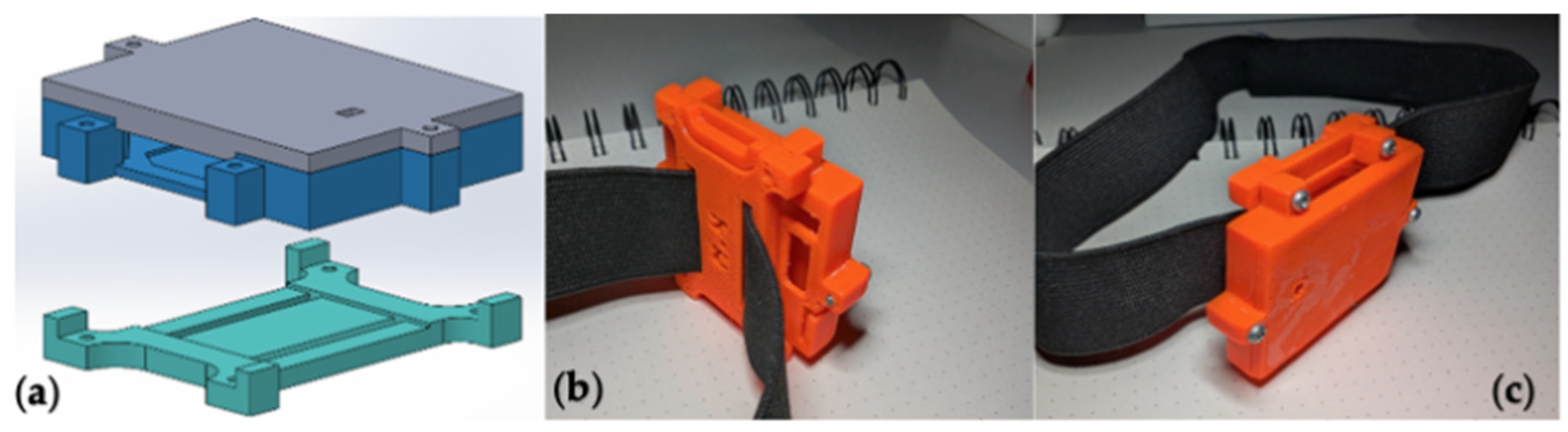
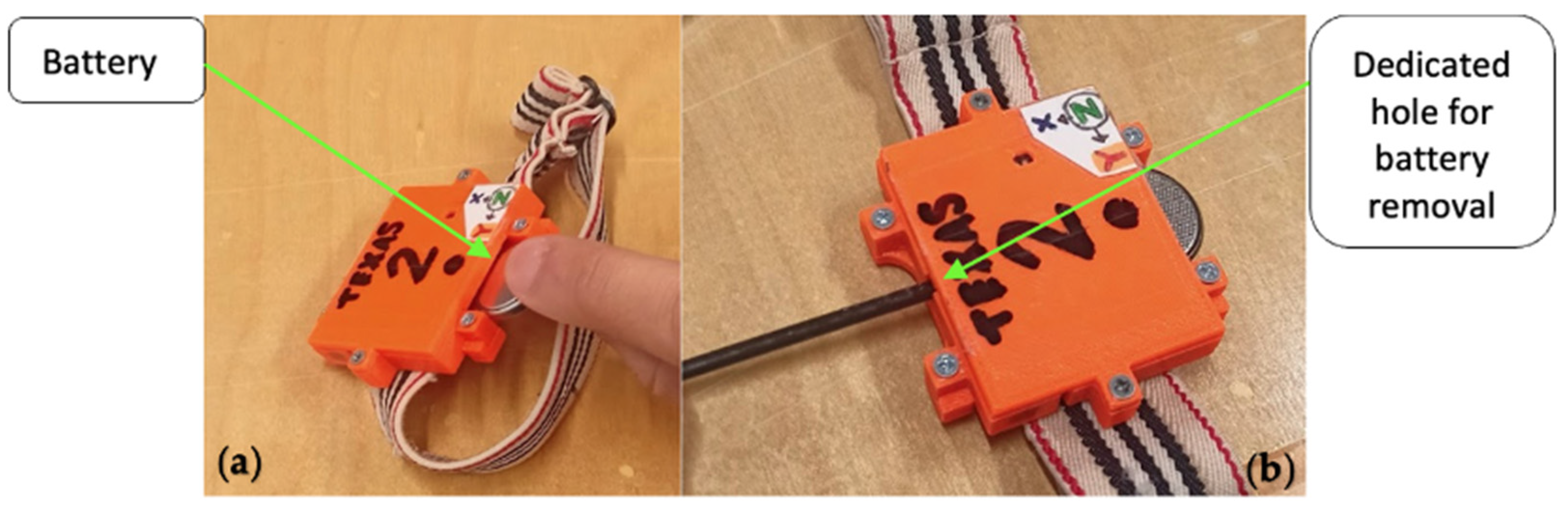
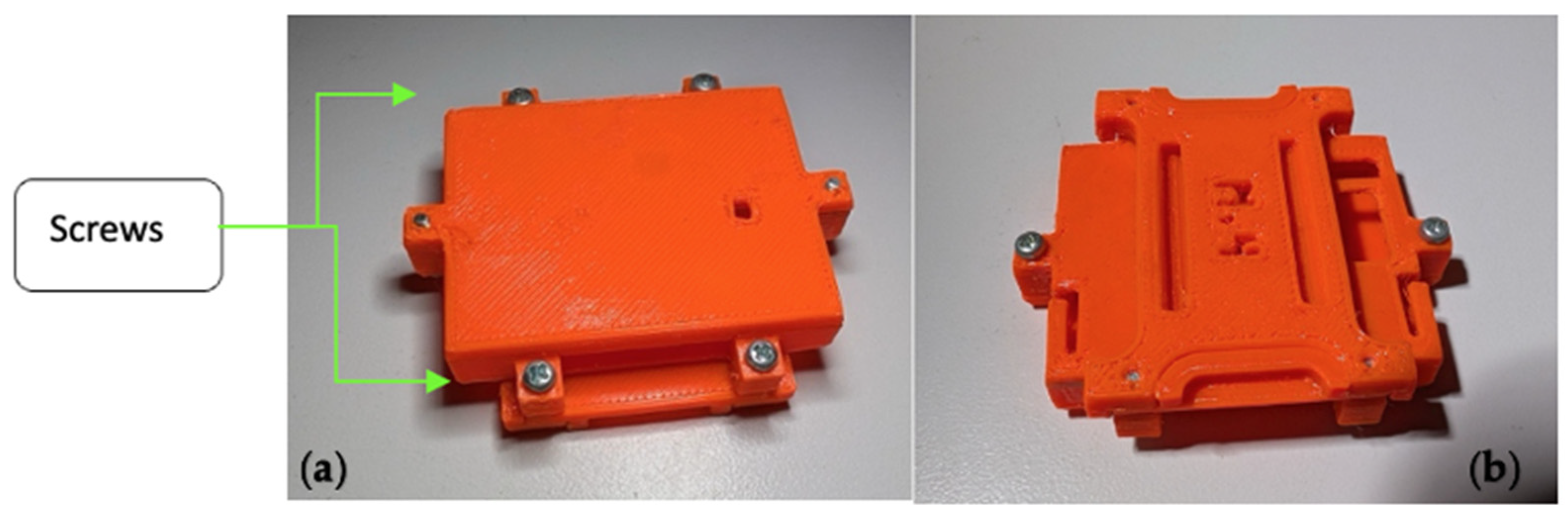
By applying the TRIZ inventive principles and the corresponding guided design solutions introduced in Section 4.3, we were able to design a wearable device housing that addresses the requirements previously identified in the analysis performed for our study case. The resulting 3D model and a prototype made using 3D printing are shown in Figure 9, Figure 10, Figure 11 and Figure 12.
Next, we will explain how the TRIZ-guided design solutions were implemented and how they address contradictions C1 to C5 of our study case:
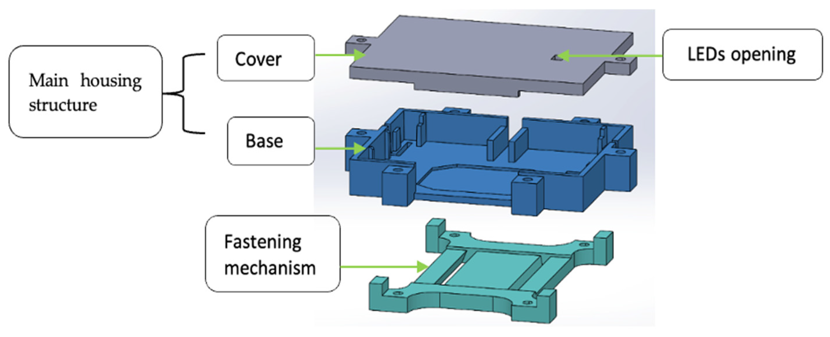
  • For C1 principle “#1 Segmentation”: The fastening function was separated from the protective enclosure to avoid deformation and loss of fit. This was implemented by introducing a dedicated fastening module that operates independently from the main housing structure (see Figure 9), improving attachment stability without compromising sensor protection.
  • For C2 principle “#17 Another dimension”: The limitation of unreliable attachment methods was addressed by introducing a dedicated structural interface for fastening. This was implemented through a fastening frame with specialized holes for straps, which properly guides and secures the fastening mechanism, preventing slippage and improving integration between components (see Figure 10).
  • For C3 principle “#17 Another dimension”: The conflict between ease of battery replacement and sensor protection was addressed by introducing alternative access paths within the housing geometry. This was implemented by incorporating openings that allow battery insertion and extraction without disassembling the device, preserving enclosure integrity (see Figure 11).
  • For C4 principle “#40 Composite materials”: The need to maintain sensor integrity while allowing controlled access was addressed by combining different structural elements and materials within the housing. This was implemented through a modular assembly forming the main housing structure (cover and base) (Figure 9), reinforced with metal screws, which improves structural resistance and limits unintended access while maintaining accessibility for maintenance (see Figure 12).
  • For C5 principle “#3 Local quality”: The need to enhance visibility during motion tracking was addressed by modifying a local property of the system without affecting its structural performance. In this context, color was identified as the most relevant attribute to adapt. Although the contradiction matrix suggested principle #3, the specific implementation aligns more directly with principle “#32 Color change”, which was incorporated as a complementary interpretation. This was implemented by selecting a high-contrast orange color for the housing, improving visual tracking during video-based analysis (see Figure 12).

4.5. User Evaluation and Fulfillment of Designer Requirements

To validate that the application of our proposed methodology leads to a device housing design that enables the SensorTag to become wearable, a usability evaluation of the solution was conducted. This evaluation covers aspects such as user satisfaction and efficiency.
To perform the evaluation, 153 volunteers were recruited to wear the resulting wearable device and were instructed to perform a series of exercises and movements. Different observations and corresponding notes were taken while the users performed the exercises to assess if the designer requirements were fulfilled. Afterwards, the users were required to fill in a questionnaire to evaluate user satisfaction while using the wearable device.
Next, the experimental procedure followed to perform the evaluation is introduced. Afterwards we present the results of the evaluation of user satisfaction followed by a discussion of how the designer requirements are fulfilled.

4.5.1. Experimental Procedure

As mentioned in the Recruitment and Ethical Considerations section, for our study case user evaluation was performed by recruiting 153 volunteers within the students at the Autonomous University of Baja California (UABC), Ensenada, Mexico. The recruitment of participants and data collection through questionnaires began on 10 July 2025 and ended on 18 August 2025. After fully explaining the experimental procedure and purpose of the study, the volunteers were presented with the option to participate or not participate in the study. Those who accepted were further asked to provide written informed consent prior to inclusion in the study, which is in accordance with the ethical guidelines approved by the Bioethics Committee of CICESE. General participant demographics are shown in Table 6.
Once volunteers accepted to participate, groups consisting of 4 to 5 participants were formed and an appointment was scheduled to provide detailed instructions and indications, perform the experiment, and fill in a questionnaire aimed at assessing user satisfaction. The main instructions provided to the participants prior to performing the experiment were as follows:
  • Placement instructions: It was required that each participant autonomously collocated two wearable sensors in specific positions of a body extremity (e.g., a leg). This is a typical usage scenario when collecting movement-related data, e.g., see [58]. Placement instructions were verbally provided aided by images showing specific placement examples to aid correct interpretation of the instructions. An example of the graphical aids used is shown in Figure 13. This figure shows the intended placement of two wearable sensors to capture movement data for one leg. Sensor 1 was placed on the middle lateral region of the right thigh, and sensor 2 was positioned between the midpoint of the knee and the ankle, in the anterior region of the leg.
  • Exercises instructions: To simulate a real physiotherapy scenario, users were instructed to perform a series of typical rehabilitation exercises, e.g., [59]. Instructions to perform the exercises were provided in printed form and reinforced with practical in situ examples to facilitate understanding. The exercises considered in the study were walking warm-up, single-leg balance, quadriceps stretching, heel raises, side-lying hip abduction, standing hip abduction, and squats.

4.5.2. User Satisfaction

Once the exercise routine was completed, participants were provided with a QR code directing them to an online usability questionnaire. This questionnaire was developed based on the Telehealth Usability Questionnaire (TUQ), a validated instrument for assessing telehealth usability across dimensions such as usefulness, ease of use, and user satisfaction, which served as the conceptual framework [60]. Its constructs were adapted to the specific context of wearable rehabilitation devices, emphasizing usability, comfort, safety, device stability, and perceived effectiveness. Item generation followed a structured process. An initial pool of 24 items was created based on TUQ dimensions and the relevant literature on wearable and telerehabilitation systems. The instrument includes both satisfaction and effectiveness dimensions to capture a broad perception of usability. The complete list of items and their descriptions are provided in Supplementary Tables S1 and S2. A full description of the questionnaire design, factor structure, and validation process is provided in a separate study currently under review [61].
Prior to the study performed for this section, a pilot test was conducted to evaluate item comprehension and usability, leading to the refinement and reduction in the instrument. Thus, the final user satisfaction questionnaire consisted of 21 items with Likert-type multiple-choices rated on a 9-point scale (1 = very low, 5 = neutral, 9 = very high). These items were grouped into four factors defined as follows: (1) Device Comfort and Usability, (2) User Satisfaction and Effectiveness, (3) Physical Safety and Interaction, and (4) Device Stability and Support (Supplementary Table S3). The instrument underwent reliability and validity assessment prior to deployment. Internal consistency analysis yielded a Cronbach’s α = 0.844, indicating good internal consistency. Construct validity was assessed through exploratory factor analysis (EFA), with the instrument explaining 64% of the total variance based on both statistical and conceptual criteria. Items with factor loadings ≥ 0.40 were retained, and a Varimax rotation was applied to facilitate interpretation of the factor structure. The questionnaire included items such as
  • Difficulty in using the device;
  • Discomfort when using the device;
  • Stability of the device on the body.
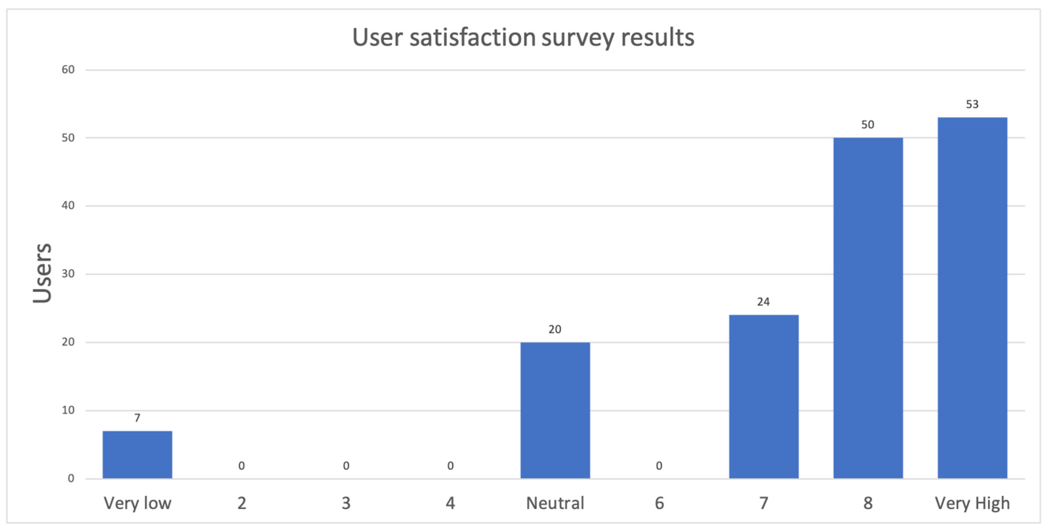
The results of the usability evaluation are summarized in Figure 14. Overall, 82.46% of participants reported high or very high levels of satisfaction. The study adopted a cross-sectional design, evaluating user perception at a single point of interaction with the device Note that this kind of evaluation is adequate for early stages of prototype development, which is the focus of the study case used to present our proposed methodology.

4.5.3. Fulfillment of Designer Requirements

Fulfillment of the designer requirements introduced in Section 3.2 was assessed during execution of the different trials carried out to evaluate user satisfaction. For example, to verify that the fastening mechanism securely attaches the SensorTag to the user leg, it was visually verified that the sensors did not move or detach from its intended position while the user performed the exercise routine. The participation of 153 volunteers with different body complexions allowed us to verify and validate that this particular designer requirement was properly fulfilled. Next, we will explain how the wearable device housing design obtained by means of our proposed methodology fulfills the designer requirements. Note that this evaluation was performed by taking notes while the 153 participants of our study were wearing the sensor and performing exercises.
  • The device must have a fastening mechanism that securely attaches it to the user’s leg. The new design features a fastening mechanism with slots specifically sized to fit various commercial smartwatch straps. This compatibility allows for the selection of straps based on the specific requirements of the location where the sensor is to be placed. In this case, long and elastic straps were chosen, ensuring a secure and comfortable attachment of the sensor to the leg.
  • The device housing and the fastening mechanism must ensure that the sensor’s position is maintained despite user movement: The dimensions and shape of the fastening mechanism prevent slipping between the housing and the strap, while the use of elastic straps ensures that the casing stays in place during user movements. These features were validated through a satisfaction evaluation, which demonstrated that users do not need to worry about keeping the device in the correct position during exercises.
  • The device must include a dedicated access point for efficient battery extraction: The integration of dedicated openings for battery insertion and removal at the base of the device housing allows users to access the battery without disassembling the housing. As shown in Figure 11, the battery can be readily replaced when necessary.
  • The strip of the fastening mechanism should accommodate muscle contraction: Since the fastening mechanism was designed to be compatible with smartwatch straps, flexible or elastic straps were selected and used. During the exercises performed by the users, it was confirmed that the selected strap, attached to the fastening mechanism, successfully withstands muscle contractions, such as those involved in squats and quadriceps stretches.
  • The device housing must restrict children’s access to the sensor: The level of protection against intentional tampering was increased by incorporating screws, as shown in Figure 12, which make access more difficult for children.
  • The fit between the device housing and the SensorTag must be tight, such that internal bouncing of the SensorTag within the housing is non-existent: The shape and dimensions of the device housing cover and base are based on the original commercial housing of the sensor, ensuring a tight fit for the sensor, as shown in Figure 15.
  • The designed device housing must provide additional protection compared to the commercial housing: The thickness of the device housing walls was increased (compared to the original housing) and the use of screws as an assembly method was incorporated. These changes increased the level of protection of the sensor against shocks and drops.
  • The strap of the fastening mechanism must be comfortable for the user (avoiding uncomfortable tension caused when using Velcro): The satisfaction measurement corroborated the comfort of the selected elastic strap on the measured leg.
  • The strap must allow for adjusting the diameter for different extremities: The compatibility of the fastening mechanism with commercial straps allows the use of straps of varying lengths and materials, facilitating placement on different parts of the limbs and accommodating diverse body types. Furthermore, it is noted that the selected strap was successfully used by all 153 users who participated in the satisfaction evaluation.
  • Once attached, the device housing must allow visibility of the operational LEDs: The segmentation of the designed device housing includes an opening in the cover (see Figure 9) for continuous monitoring of the functioning LEDs, allowing control over the connection and verification of whether the sensor is on or off.
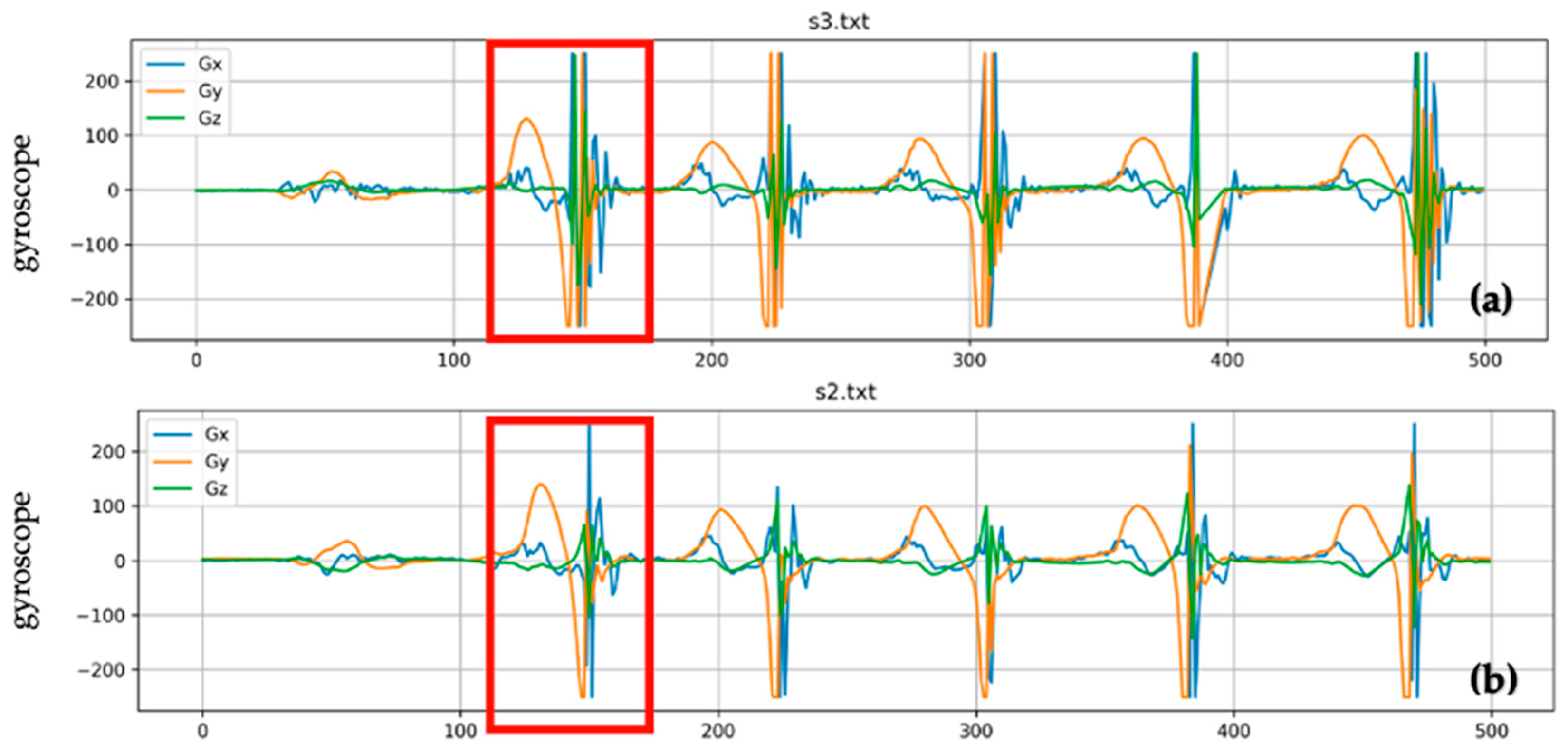
Complementary quantitative testing confirmed that the TRIZ-designed housing improves IMU signal quality by reducing motion artifacts. To illustrate this, Figure 16 shows a comparison of signals captured when using the SensorTag with the quick Velcro-based adaptation (Figure 16a) and the resulting TRIZ-designed housing (Figure 16b). Note that by using the TRIZ-designed housing, less noise and motion-related artifacts are introduced in the captured signal. Thus, the housing design obtained through our proposed methodology provides enhanced measurement fidelity for movement-capture applications compared to the quick Velcro-based adaptations shown in Figure 6, Figure 7 and Figure 8.
The robustness of the strap interface and fastening mechanism was evaluated during user trials involving functional rehabilitation exercises, including warm-up walking, single-leg balance, quadriceps stretching, heel raises, side-lying abduction, hip abduction, and squats. Across the 153 participants, no issues related to strap slippage, detachment, or instability were reported while performing these activities.

5. Discussion

With the results obtained in this study, the results indicate that the proposed TRIZ-based methodology is effective for guiding the design of wearable devices, even from the early stages of prototype development when the use of generic OTS boards like the SensorTag is relatively common.
In the application example, by systematically identifying design contradictions (for example, between secure fastening and user comfort, or between sensor protection and battery access) and applying the contradiction matrix to select appropriate inventive principles, we developed a housing that provides secure attachment, ease of battery replacement, robust IMU protection, and clear visibility of operational LEDs. These features satisfy the technical requirements of the designers, while providing the OTS IMU with satisfactory usability and functionality as a wearable device. This was confirmed through usability evaluation, where 86% of users reported high or very high satisfaction.
Also, quantitative testing indicated that the TRIZ-designed housing improves measurement repeatability and reduces motion artifacts compared to the quick Velcro-based adaptations (Figure 16). Thus, the presented results illustrate how the proposed TRIZ-based methodology can be used in the design process of wearable devices to improve usability and potentially contribute to improved device performance.
To further highlight the contribution of this work, Table 7 summarizes a comparative analysis between the proposed methodology and representative TRIZ-based studies reported in the literature. The comparison highlights variations in the use of TRIZ, system scope, user-centered considerations, and validation approaches, positioning the proposed methodology within the broader landscape of TRIZ applications in engineering.
Note in Table 7 how prior art has reported the use of TRIZ to address innovation at the component, algorithm, process, and conceptual levels. However, these works have not addressed how TRIZ can be applied to the design of wearable devices from the early stages of prototype development. This is an important topic, because the design of solutions based on wearable IMU devices (e.g., body motions [14,15,16,17]) usually starts by performing quick adaptations (or workarounds) to attach OTS IMU solutions (or custom integrations) to the body. Furthermore, while many TRIZ applications focus solely on resolving technical contradictions [70,71,72,73], our study demonstrates how structured innovation can translate into wearable designs that are well accepted by users, even when they are based on OTS solutions (or custom integrations). This positions this work as a contribution toward bridging systematic TRIZ-based innovation and user-centered design approaches in wearable device development.
A limitation of the present study is that the evaluation relied on short-term usability trials with a relatively homogeneous sample of young participants. Also, it is worth mentioning that currently long-term trials are being carried out to assess the long-term performance of the proposed solution.

6. Conclusions

In the design of wearable devices, it is customary to begin the development process by using OTS solutions or custom IMU integrations. However, these solutions are not commonly designed to be worn by users, and thus quick workarounds are typically used by developers to attach OTS IMUs (or custom integrations) to the body. Whereas this approach allows wearable developers to quickly start with the design process of hardware and software, the workarounds are often implemented without following a systematic design rationale. This paper introduced a TRIZ-based methodology to systematically guide the transition from a stock OTS IMU solution to a wearable device, even from the early prototyping stages. Thus, the main contribution of this work lies in providing a methodological framework to apply TRIZ even at the early stages of wearable device design.
By applying the proposed methodology to the study case, we have shown how different challenges arising in the early stages of prototype development can be effectively addressed in a systematic way by applying the inventive principles proposed by TRIZ. Furthermore, the added value of the methodology is reflected in the presented results, as the resulting wearable device housing achieved 86% of high or very high user satisfaction and all designer requirements were successfully met. These outcomes suggest measurable improvements in both technical performance and user experience, compared to what would typically be expected from conventional design approaches. Therefore, the methodology proposed in this paper provides a rigorous and repeatable process for resolving design contradictions, enhancing ergonomics, and improving usability beyond conventional adaptation or prototyping practices in the design process of wearable devices.
Based on the results of the user evaluation and the fulfillment of designer requirements, it can be asserted that the proposed TRIZ-based methodology is a valuable tool for the design of wearable devices. Future work will include benchmarking the TRIZ-based design methodology against alternative approaches, such as QFD-only or heuristic redesign, to quantitatively assess the additional value of systematic inventive problem solving in wearable device design. This will provide a more rigorous comparison and further validate the effectiveness of TRIZ in real-world applications.

Supplementary Materials

The following supporting information can be downloaded at: https://www.mdpi.com/article/10.3390/app16115270/s1, Table S1: Complete list of satisfaction questionnaire items. Table S2: Complete list of effectiveness questionnaire items. Table S3: Grouping into factors of the 21 items included in the final usability questionnaire. The items were selected among those presented in Tables S1 and S2. The loading factor for each item is provided in the last column. Table S4: Comparative summary of TRIZ-based methods. References [74,75,76] are cited in the Supplementary Materials.

Author Contributions

E.A.M.-G.: Investigation, Methodology, Validation, Visualization, Writing—original draft. M.A.C.-P.: Investigation, Validation, Visualization, Resources, Writing—review and editing. S.V.-R.: Conceptualization, Project administration, Supervision, Formal analysis, Validation, Writing—original draft. J.E.O.-T.: Conceptualization, Project administration, Supervision, Methodology, Validation, Writing—review and editing. A.G.-M.: Formal analysis, Resources, Writing—review and editing. C.C.-W.: Methodology. J.C.C.-G.: Methodology. J.L.G.-A.: Data curation. C.R.-S.: Data curation, Resources. All authors have read and agreed to the published version of the manuscript.

Funding

Part of this research was partially supported by PhD scholarships awarded to Efrain Atenogenes Mejia-Gonzalez (CVU 769348) and Miguel Angel Castro-Perez (CVU 917830), which were granted by the Secretaría de Ciencia, Humanidades, Tecnología e Innovación (SECIHTI).

Institutional Review Board Statement

This research protocol was reviewed and approved by the Bioethics Committee of the Centro de Investigation Científica y de Educación Superior de Ensenada (CICESE Research Center), Ensenada, B.C., Mexico, with approval and registration number BIOETICA_HUM_2025_06. All participants provided their informed consent in writing. The study was conducted in accordance with the Declaration of Helsinki.

Data Availability Statement

The satisfaction survey was conducted following established methodological standards to ensure validity and reliability. While the specific results are part of ongoing research that will be published separately, the questionnaire design, data collection, and analysis adhered to rigorous protocols, including informed consent and anonymity.

Acknowledgments

Special thanks to the ARTS Research Group of the Centro de Investigación Científica y de Educación Superior de Ensenada, Baja California (CICESE Research Center, México), for their contribution to the design, printing, and support provided for the wearable device used in the development of this research. Thanks to Melanie Shantal Gómez Fernández for her valuable help during data collection.

Conflicts of Interest

The authors declare no conflicts of interest.

References

  1. World Health Organization. Rehabilitation in Health Systems: Guide for Action; World Health Organization: Geneva, Switzerland, 2017. [Google Scholar]
  2. Kabir, P.; Zareinejad, M.; Talebi, H.A.; Soleimanifar, M. An inflatable soft wearable knee rehabilitation device: Design, fabrication, control and preliminary evaluation. Mechatronics 2024, 102, 103233. [Google Scholar] [CrossRef]
  3. López-Liria, R.; Vega-Ramírez, F.; Catalán-Matamoros, D.; Padilla Góngora, D.; Martínez-Cortés, M.; Mesa-Ruiz, A. [Home care rehabilitation and physiotherapy in knee prosthesis]. An. Sist. Sanit. Navar. 2012, 35, 99–113. [Google Scholar] [CrossRef]
  4. Banihani, J.; Choukou, M.A. A home-based hand rehabilitation platform for hemiplegic patients after stroke: A feasibility study. Heliyon 2024, 10, e35565. [Google Scholar] [CrossRef]
  5. Pan, H.; Wang, H.; Li, D.; Zhu, K.; Gao, Y.; Yin, R.; Shull, P.B. Automated, IMU-based spine angle estimation and IMU location identification for telerehabilitation. J. Neuroeng. Rehabil. 2024, 21, 96. [Google Scholar] [CrossRef]
  6. Bell, K.M.; Onyeukwu, C.; McClincy, M.P.; Allen, M.; Bechard, L.; Mukherjee, A.; Hartman, R.A.; Smith, C.; Lynch, A.D.; Irrgang, J.J. Verification of a portable motion tracking system for remote management of physical rehabilitation of the knee. Sensors 2019, 19, 1021. [Google Scholar] [CrossRef]
  7. Cottam, D.S.; Campbell, A.C.; Davey, P.C.; Kent, P.; Elliott, B.C.; Alderson, J.A. Measurement of uni-planar and sport specific trunk motion using magneto-inertial measurement units: The concurrent validity of Noraxon and Xsens systems relative to a retro-reflective system. Gait Posture 2022, 92, 129–134. [Google Scholar] [CrossRef]
  8. Zhu, X.; Jia, F.; Kong, L.; Zhang, H.; Zhang, S.; Zhang, Y.; Wang, L. Daily walking kinematic characteristics of the elderly in different residential settings: Experimental study on Chinese community-living elderly and long-term nursing home residents. Aging Clin. Exp. Res. 2023, 35, 2531–2542. [Google Scholar] [CrossRef]
  9. Serena, R.S.; Hinterwimmer, F.; Burgkart, R.; von Eisenhart-Rothe, R.; Rueckert, D. The use of artificial intelligence and wearable inertial measurement units in medicine: Systematic review. JMIR Mhealth Uhealth 2025, 13, e60521. [Google Scholar] [CrossRef]
  10. Brito, A.V.; Fonseca, P.; Costa, M.J.; Cardoso, R.; Santos, C.C.; Fernandez-Fernandez, J.; Fernandes, R.J. The influence of kinematics on tennis serve speed: An in-depth analysis using Xsens MVN Biomech Link technology. Bioengineering 2024, 11, 971. [Google Scholar] [CrossRef]
  11. Iluk, A. Flight Controller as a Low-Cost IMU Sensor for Human Motion Measurement. Sensors 2023, 23, 2342. [Google Scholar] [CrossRef]
  12. Espitia-Mora, L.A.; Vélez-Guerrero, M.A.; Callejas-Cuervo, M. Development of a Low-Cost Markerless Optical Motion Capture System for Gait Analysis and Anthropometric Parameter Quantification. Sensors 2024, 24, 3371. [Google Scholar] [CrossRef]
  13. Yin, M.; Li, J.; Wang, T. A Low-Cost Inertial Measurement Unit Motion Capture System for Operation Posture Collection and Recognition. Sensors 2024, 24, 686. [Google Scholar] [CrossRef]
  14. Voisard, C.; de l’Escalopier, N.; Ricard, D.; Oudre, L. Automatic gait events detection with inertial measurement units: Healthy subjects and moderate to severe impaired patients. J. Neuroeng. Rehabil. 2024, 21, 104. [Google Scholar] [CrossRef]
  15. Wudhiphan, W.; Suthisoontrin, T.; Vanijkachorn, P.; Visutsak, P. An IoT-based multi-sensory intelligent device for bedridden elderly monitoring. ECTI-CIT. Trans. 2024, 18, 136–146. [Google Scholar]
  16. Sumaiya, M.N.; Vachanamruth, G.S.; Naveen, V.; Varshitha, C.; Yashaswini, V.P. Wearable sleeve for physiotherapy assessment using ESP32 and IMU sensor. In Computational Intelligence and Deep Learning Methods for Neuro-Rehabilitation Applications; Hemanth, D.J., Ed.; Academic Press: Cambridge, MA, USA, 2024; pp. 101–119. [Google Scholar]
  17. Bhongade, A.; Gupta, R.; Gandhi, T.K.; Ap, P. Intelligent single IMU sensor module for gait temporal parameter estimation. TechRxiv 2024. [Google Scholar] [CrossRef] [PubMed]
  18. Camomilla, V.; Bergamini, E.; Fantozzi, S.; Vannozzi, G. Trends Supporting the In-Field Use of Wearable Inertial Sensors for Sport Performance Evaluation: A Systematic Review. Sensors 2018, 18, 873. [Google Scholar] [CrossRef]
  19. Francés-Morcillo, L.; Morer-Camo, P.; Rodríguez-Ferradas, M.I.; Cazón-Martín, A. Wearable Design Requirements Identification and Evaluation. Sensors 2020, 20, 2599. [Google Scholar] [CrossRef]
  20. Cnytskyy, I.; Hlinenko, L.; Yakovenko, Y.; Horbay, O.; Koda, E.; Rusakov, K.; Yankiv, V.; Humenuyk, R.; Polyansky, P.; Berezovetskyi, S.; et al. Problem-oriented modelling for biomedical engineering systems. Appl. Sci. 2022, 12, 7466. [Google Scholar] [CrossRef]
  21. Ördek, B.; Russo, D.; Spreafico, C. FMEA-TRIZ Analysis of Reused Ti6Al4V Powder in SLM. Procedia CIRP 2025, 136, 32–37. [Google Scholar]
  22. Bertoncelli, T.; Gronauer, B.; Nähler, H. TRIZ Barcamp exercise: Ideas for wearable defibrillators. In New Opportunities for Innovation Breakthroughs for Developing Countries and Emerging Economies, Proceedings of the 19th International TRIZ Future Conference (TFC), Marrakesh, Morocco; Springer: Cham, Switzerland, 2019; pp. 257–265. [Google Scholar]
  23. Rong, H.; Liu, W.; Li, J.; Zhou, Z. Product innovation design process combined Kano and TRIZ with AD: Case study. PLoS ONE 2024, 19, e0296980. [Google Scholar] [CrossRef]
  24. Ng, P.K.; Prasetio, M.D.; Liew, K.W.; Lim, B.K.; Oktafiani, A.; Salma, S.A.; Safrudin, Y.N. A TRIZ-inspired conceptual development of a roof tile transportation and inspection system. Buildings 2022, 12, 1456. [Google Scholar] [CrossRef]
  25. Gräbe, H.-G. Systems, resources, and systemic development in TRIZ. In Systematic Innovation Partnerships with Artificial Intelligence and Information Technology; Springer: Cham, Switzerland, 2022; pp. 96–108. [Google Scholar]
  26. Komarudin, K.; Suherman, S.; Vidákovich, T. The RMS teaching model with brainstorming technique and student digital literacy as predictors of mathematical literacy. Heliyon 2024, 10, e33877. [Google Scholar] [CrossRef]
  27. Shen, D.; Yao, X.; Bao, D.; Yu, Y. for Content categorization for memory retrieval: A method evaluating design performance. PLoS ONE 2023, 18, e0280459. [Google Scholar] [CrossRef]
  28. Sari, E.M.; Irawan, A.P.; Wibowo, M.A.; Siregar, J.P.; Tamin, R.Z.; Praja, A.K.A.; Dewi, M.P. Challenge and Awareness for Implemented Integrated Project Delivery (IPD) in Indonesian Projects. Buildings 2023, 13, 262. [Google Scholar] [CrossRef]
  29. Nolan, V. Whatever happened to Synectic. Creat. Innov. Manag. 2003, 12, 24–27. [Google Scholar] [CrossRef]
  30. Ekmekci, I.; Nebati, E.E. TRIZ methodology and applications. Procedia Comput. Sci. 2019, 158, 303–315. [Google Scholar] [CrossRef]
  31. Tang, S.; Wan, S.; Li, X.; Ding, G.; Qi, X. Design of multi-task scene image acquisition system in a spacecraft based on TRIZ. In Advances in Mechanical Design: ICMD 2023; Mechanisms and Machine Science; Tan, J., Liu, Y., Huang, H.Z., Yu, J., Wang, Z., Eds.; Springer: Singapore, 2024; Volume 155, pp. 16–24. [Google Scholar]
  32. Zhang, Y.; Sun, Z.; Liu, P. Application of TRIZ theory in power electronic circuits. In Proceedings of 2023 International Conference on Wireless Power Transfer (ICWPT2023); Lecture Notes in Electrical Engineering; Cai, C., Qu, X., Mai, R., Zhang, P., Chai, W., Wu, S., Eds.; Springer: Singapore, 2024; Volume 1159, pp. 44–53. [Google Scholar]
  33. Sojka, V.; Lepsik, P. Tools of Theory of Inventive Problem Solving Used for Process Improvement—A Systematic Literature Review. Processes 2025, 13, 226. [Google Scholar] [CrossRef]
  34. Shao, P.; Tan, R.; Peng, Q.; Zhang, L.; Wang, K.; Dong, Y. Problem-solving in product innovation based on the Cynefin framework-aided TRIZ. Appl. Sci. 2022, 12, 4157. [Google Scholar]
  35. Harthik, T.; Kawatkar, A.; Bharani, R. Application of TRIZ methodology in enhancing product life cycle of an automotive diesel engine. In WCX SAE World Congress Experience; SAE Tech Paper; SAE International: Warrendale, PA, USA, 2024. [Google Scholar] [CrossRef]
  36. Dhalmahapatra, K.; Verma, A.; Maiti, J. An integrated TRIZ coupled safety function deployment and capital budgeting methodology for occupational safety improvement: A case of manufacturing industry. Process Saf. Environ. Prot. 2022, 165, 31–45. [Google Scholar]
  37. Gao, C.; Guo, L.; Gao, F.; Yang, B. Innovation design of medical equipment based on TRIZ. Technol. Health Care 2015, 23, S269–S276. [Google Scholar] [CrossRef] [PubMed]
  38. Santoso, G.; Ammarullah, M.I.; Sugiharto, S.; Hidayat, T.; Khoeron, S.; Bayuseno, A.P.; Jamari, J. TRIZ-based method for developing a conceptual laparoscopic surgeon’s chair. Cogent Eng. 2024, 11, 2298786. [Google Scholar] [CrossRef]
  39. Rahim, Z.A.; Iqbal, M.S.; Abu Bakar, N. A systematic approach to design and develop patented stimuli-responsive polymers for biomedicine applications: TRIZ–patent literature review methodology. J. Chem. Technol. Biotechnol. 2025, 100, 2512–2521. [Google Scholar] [CrossRef]
  40. Ekmekci, I.; Koksal, M. TRIZ methodology and an application example for product development. Procedia Soc. Behav. Sci. 2015, 195, 2689–2698. [Google Scholar] [CrossRef]
  41. Panagiotou, C.; Faliagka, E.; Antonopoulos, C.P.; Voros, N. Multidisciplinary ML Techniques on Gesture Recognition for People with Disabilities in a Smart Home Environment. AI 2025, 6, 17. [Google Scholar] [CrossRef]
  42. Alexan, A.; Alexan, A.; Oniga, S. SoC based IoT sensor network hub for activity recognition using ML.net framework. In 2020 IEEE 26th International Symposium for Design and Technology in Electronic Packaging (SIITME); IEEE: Piscataway, NJ, USA, 2020; pp. 184–187. [Google Scholar]
  43. González-Cañete, F.J.; Casilari, E. Consumption Analysis of Smartphone based Fall Detection Systems with Multiple External Wireless Sensors. Sensors 2020, 20, 622. [Google Scholar] [CrossRef]
  44. Alexan, A.; Alexan, A.; Oniga, S.; Pap, I.A. Assisted living personal tracker framework. In 2018 IEEE International Conference on Automation, Quality and Testing, Robotics (AQTR); IEEE: Piscataway, NJ, USA, 2018; pp. 1–4. [Google Scholar]
  45. Sighvatsson, H.; Guðmundsson, K.S.; Árnason, S.S.; Sighvatsdóttir, Á.G.; Andersen, K.; Þorbergsson, H. Wearable heart monitor. In 2021 International Conference on Biomedical Innovations and Applications (BIA); IEEE: Piscataway, NJ, USA, 2022; pp. 13–17. [Google Scholar]
  46. Casilari, E.; Santoyo-Ramón, J.A.; Cano-García, J.M. Analysis of a smartphone-based architecture with multiple mobility sensors for fall detection. PLoS ONE 2016, 11, e0168069. [Google Scholar]
  47. McLeod, K.; Girchenko, L.; Spenler, P.; Spachos, P. A smartphone-based wellness assessment using mobile sensors. In 2018 IEEE Global Conference on Signal and Information Processing (GlobalSIP); IEEE: Piscataway, NJ, USA, 2018; pp. 454–458. [Google Scholar]
  48. Sun, H.; Lu, Z.; Chen, C.L.; Cao, J.; Tan, Z. Accurate human gesture sensing with coarse-grained RF signatures. IEEE Access 2019, 7, 81227–81245. [Google Scholar] [CrossRef]
  49. Malvik, T.O. TRIZ as an innovation tool for opportunity management and Lean Construction. Procedia Comput. Sci. 2025, 256, 1459–1466. [Google Scholar] [CrossRef]
  50. Reich, Y.; Hatchuel, A.; Shai, O.; Subrahmanian, E. A theoretical analysis of creativity methods in engineering design: Casting and improving ASIT within C–K theory. J. Eng. Des. 2012, 23, 137–158. [Google Scholar] [CrossRef]
  51. Feng, L.; Niu, Y.; Liu, Z.; Wang, J.; Zhang, K. Discovering Technology Opportunity by Keyword-Based Patent Analysis: A Hybrid Approach of Morphology Analysis and USIT. Sustainability 2020, 12, 136. [Google Scholar]
  52. Cano-Moreno, J.D.; Cabanellas-Becerra, J.M. TRIZ10. The decalogue of technical creativity. DYNA 2018, 93, 586. [Google Scholar] [CrossRef]
  53. Cortes Robles, G. (Ed.) TRIZ in Latin America: Case Studies; Springer: Cham, Switzerland, 2023. [Google Scholar]
  54. Hassanijajini, H.; Hassanimohebi, Z.; Gardoni, M. Preparation of Archi-TRIZ matrix for accelerating innovation in building design process. Int. J. Des. Manag. Prof. Pract. 2024, 19, 35–53. [Google Scholar] [CrossRef]
  55. Yao, K.C.; Chen, L.Y.; Li, K.Y.; Chang, Y.N.; Xu, J.R.; Huang, W.L.; Ho, W.S. An innovative design for cleansing, deodorization, and pest control in drain covers: Application of the TRIZ method and human factors engineering. Machines 2024, 12, 621. [Google Scholar] [CrossRef]
  56. Gdoura, R.; Houssin, R.; Chibane, H.; Dhouib, D.; Coulibaly, A. A new TRIZ-based approach to design an innovative production system by integrating lean tools and functionalities. In World Conference of AI-Powered Innovation and Inventive Design. TFC 2024; Cavallucci, D., Brad, S., Livotov, P., Eds.; Springer: Cham, Switzerland, 2025; Volume 736, p. 2. [Google Scholar]
  57. Mamedov, A.; Dinc, A.; Behbehani, H.; Al Quoud, T.; Alotaibi, O.; Alotaibi, M.; Alqallaf, S. Application of theory of inventive problem solving (TRIZ) and quality function deployment (QFD) methodologies for design and manufacturing of a regenerative braking system. Eng. Sci. 2024, 31, 1263. [Google Scholar] [CrossRef]
  58. Kobsar, D.; Ferber, R. Wearable Sensor Data to Track Subject-Specific Movement Patterns Related to Clinical Outcomes Using a Machine Learning Approach. Sensors 2018, 18, 2828. [Google Scholar] [CrossRef]
  59. Naderi, A.; Fallah Mohammadi, M.; Heidaralizadeh, A.; Moen, M.H. Effects of integrating lower-leg exercises into a multimodal therapeutic approach on medial tibial stress syndrome management among recreational runners: A randomized controlled study. Orthop. J. Sports Med. 2025, 13. [Google Scholar] [CrossRef]
  60. Parmanto, B.; Lewis, A.N., Jr.; Graham, K.M.; Bertolet, M.H. Development of the Telehealth Usability Questionnaire (TUQ). Int. J. Telerehabilitation 2016, 8, 3–10. [Google Scholar] [CrossRef] [PubMed]
  61. Mejía González, E.A.; Castro-Pérez, M.Á.; Villarreal-Reyes, S.; Camargo-Wilson, C.; Cano-Gutiérrez, J.C.; Galaviz Mosqueda, G.A.; Ramírez-Ríos, L.Y.; Olguín-Tiznado, J.E. Psychometric Properties and Initial Validation of the Usability Questionnaire for Rehabilitation Wearable Devices in Telerehabilitation. Int. J. Telerehabilitation, 2026; in process.
  62. Yao, K.-C.; Cheng, C.-N.; Li, K.-Y.; Xu, J.-R.; Huang, W.-L.; Ho, W.-S.; Liao, C.-W.; Yang, S.-C.; Hsiao, H.-L.; Lin, Y.-C.; et al. Sustainable Hygiene Solutions: Developing a Foot-Operated Door Mechanism for Communal Spaces Using TRIZ and Universal Design Principles. Sustainability 2024, 16, 8415. [Google Scholar] [CrossRef]
  63. Zuo, B.; Liu, X.; Wang, H.; Fan, C. TRIZ-Based Design, Finite Element Simulation, and Experimentation of a Linear Motor for Cleaning Machines. Adv. Mech. Eng. 2025, 17, 16878132251400181. [Google Scholar] [CrossRef]
  64. Ang, M.C.; Ng, K.W. Minimising Printed Circuit Board Assembly Time Using the Bees Algorithm with TRIZ-Inspired Operators. In Advanced Manufacturing Systems and Technologies; Springer: Cham, Switzerland, 2023. [Google Scholar]
  65. Trapp, S.; Warschat, J. LLM-based Extraction of Contradictions from Patents. arXiv 2024, arXiv:2403.14258. [Google Scholar] [CrossRef]
  66. Rahardjo, B.; Winnyarto, S.T.; Tjendra, V. Integration of green lean six sigma and TRIZ methodology for sustainable green manufacturing: A case study in plywood industry. Int. J. Lean Six Sigma 2025, 16, 1394–1414. [Google Scholar] [CrossRef]
  67. Wang, C.-N.; Shiue, N.-C.; Phan, V.-T.; Hong, D.-Q. A TRIZ-Based Experimental Design Approach to Enhance Wave Soldering Efficiency in Electronics Manufacturing Processes. Processes 2025, 13, 3733. [Google Scholar] [CrossRef]
  68. Ge, S.; Huang, S.; Song, X.; Sun, Y.; Wang, N.; Qi, K.; Zhao, X.; Li, J.; Cui, Y. Comparing TRIZ and Brainstorming in Human–Agent Design Collaboration: Effects on Cognitive Processes and Performance. Artif. Intell. Eng. Des. Anal. Manuf. (AIEDAM) 2025, 39, e21. [Google Scholar] [CrossRef]
  69. Čok, V.; Samsa, L.; Brojan, M.; Tavčar, J.; Vukašinović, N. Case Study: Is There a Space for TRIZ in the Era of ChatGPT? Proc. Des. Soc. 2025, 5, 871–880. [Google Scholar] [CrossRef]
  70. Song, D.; Liu, L.; Zhu, T.; Zhang, S.; Huang, Y. B-FMEA-TRIZ model for scheme decision in conceptual product design: A study on upper-limb hemiplegia rehabilitation exoskeleton. Heliyon 2024, 10, e30684. [Google Scholar] [CrossRef] [PubMed]
  71. Chang, C.P.; Lin, Y.H. Applying TRIZ to Improve the Structure of Walkers. Appl. Mech. Mater. 2014, 487, 366–369. [Google Scholar] [CrossRef]
  72. Shie, A.-J.; Wu, W.-F.; Yang, M.; Wan, X.; Li, H. Design and process optimization of combined medical and elderly care services: An integrated service blueprint–TRIZ model. Front. Public Health 2022, 10, 965443. [Google Scholar] [CrossRef]
  73. Ramírez-Ríos, L.Y.; Camargo-Wilson, C.; Olguín-Tiznado, J.E.; López-Barreras, J.A.; Inzunza-González, E.; García-Alcaraz, J.L. Design of a modular plantar orthosis system through the application of TRIZ methodology tools. Appl. Sci. 2021, 11, 2051. [Google Scholar] [CrossRef]
  74. Schöfer, M.; Maranzana, N.; Aoussat, A.; Gazoa, C.; Bersano, G. The Value of TRIZ and Its Derivatives for Interdisciplinary Group Problem Solving. Procedia Eng. 2015, 131, 894–903. [Google Scholar] [CrossRef]
  75. Nakagawa, T. A New Paradigm of Creative Problem Solving: Integration of TRIZ with USIT. Procedia Eng. 2011, 9, 52–63. [Google Scholar] [CrossRef]
  76. Gusarov, S.; Sapelnikova, S.; Valdes, J.J.; Hu, A.; Stoyanov, S.R. Integrating the Theory of Inventive Problem Solving with Large Language Models: Enhancing Reasoning for Innovation in Materials Science at the Molecular Scale. ChemEngineering 2026, 10, 54. [Google Scholar] [CrossRef]
Figure 1. Block diagram of the proposed TRIZ methodology for designing a wearable device based on an off-the-shelf (or custom integration) wireless IMU solution.
Applsci 16 05270 g001
Figure 2. Front and back views of the SensorTag used in this work as a case study to exemplify the application of the proposed methodology. The labels highlight the main characteristics of the device: (a) front view; (b) back view.
Applsci 16 05270 g002
Figure 3. Texas Instruments’ commercial housing for the SensorTag: (a) front view made of rigid plastic with a transparent finish, allowing visual access to the SensorTag and its operational LEDs; (b) back view made of rigid plastic with a black finish.
Applsci 16 05270 g003
Figure 4. Texas Instruments’ commercial sleeve designed for use with the SensorTag rigid plastic housing: (a) front view; (b) back view. The sleeve is made of a rubber-like material.
Applsci 16 05270 g004
Figure 5. Typical assembly of the SensorTag enclosure components: (a) housing inserted into the sleeve in the assembled configuration; (b) partial separation illustrating the insertion interface between the rigid housing and the sleeve.
Applsci 16 05270 g005
Figure 6. Straightforward adaptation to provide “wearability” to the SensorTag by gluing Velcro straps to the rigid plastic housing. (a) Application of adhesive to the housing surface. (b) Velcro strip attached to the housing. (c) Resulting wearable configuration when mounted on the user’s limb.
Applsci 16 05270 g006
Figure 7. Incorporation of Velcro strips to the commercial sleeve as a quick workaround to provide wearability functionality to the SensorTag.
Applsci 16 05270 g007
Figure 8. Typical placement of the SensorTag for data acquisition using the straightforward adaptations shown in Figure 6 and Figure 7: (a) configuration option 1; (b) configuration option 2.
Applsci 16 05270 g008
Figure 9. Exploded view of the wearable device housing showing its main components. The cover and base are grouped as the main housing structure, while the fastening mechanism is presented as an independent module. This configuration reflects the integration of multiple design decisions derived from the application of TRIZ principles, including functional separation and structural assembly. The figure also indicates the placement of the opening to monitor the functioning LEDs of the SensorTag.
Applsci 16 05270 g009
Figure 10. Integration of the Velcro strip into the fastening mechanism of the wearable device housing obtained through the proposed TRIZ-based methodology: (a) 3D model of the fastening mechanism; (b) back view of the 3D-printed prototype; (c) front view of the 3D-printed prototype.
Applsci 16 05270 g010
Figure 11. Battery handling features of the designed wearable device housing: (a) front view illustrating the straightforward battery insertion enabled by the housing geometry; (b) front view showing the dedicated access opening designed to facilitate battery extraction.
Applsci 16 05270 g011
Figure 12. Designed wearable device housing: (a) front view showing the screw-based assembly used to ensure structural integrity; (b) back view of the housing. The use of screws illustrates the application of TRIZ principle #40, while the high-contrast orange color demonstrates principle #13 by facilitating visual tracking during video-based motion analysis.
Applsci 16 05270 g012
Figure 13. Example of the graphical aid used to show the intended placement of the wearable sensors to capture movement data of one leg. The participants of the experimental procedure were shown this image prior to being asked to wear the sensors.
Applsci 16 05270 g013
Figure 14. Summarized results of the evaluation of user satisfaction when using the wearable device resulting from applying the design methodology proposed in this paper. Note that most users show high and very high satisfaction levels.
Applsci 16 05270 g014
Figure 15. The housing adjustment ensures a tight fit for the sensor, limiting internal bouncing of the SensorTag.
Applsci 16 05270 g015
Figure 16. Representative IMU gyroscope signal comparison during controlled impact: (a) with quick Velcro-based adaptation and (b) custom TRIZ-designed housing. The plot corresponding to the TRIZ-designed housing exhibits reduced oscillation amplitude and less noise. This indicates that fewer motion artifacts are introduced when using this housing compared to the Velcro-based adaptations. The rectangular region highlights a representative impact event within the repeated signal.
Applsci 16 05270 g016
Table 1. Technical system identification for the study case.
Technical System Name (TS)Wearable IMU-Based Device
Primary objective of the TSUse of the SensorTag as a wearable device.
Main elements that make up the TS and their functions
ELEMENT NAMEFUNCTION
1. Sensor (SensorTag Texas instruments)Collect and transmit signals from IMUs
2. Device housingProtect the sensor from the medium and serve as a frame for the fastening solution.
3. Fastening solutionKeep the device secure and usable (sensor and housing) and attached to the limb, minimizing possible slight movement or slip (arm, leg, ankle, etc.)
Description of TS operation:
The device is fastened to the measurement limb using the Velcro strips to acquire and transmit signals to the processing system
Features to be improved or eliminated
  • The commercial housing does not consider any fastening mechanism.
  • Quick workaround fastening mechanisms for the commercial housing, such as gluing Velcro strips to the rigid plastic case (see Figure 6) and passing Velcro strips through the openings of the sleeve (see Figure 7).
  • The housing must protect the sensor against accidental disassembles and prevent direct handling.
  • The strap of the fastening mechanism must facilitate attachment to body parts/limbs of different diameters.
  • When using Velcro, the sensor can become detached from the limb when a muscle is contracted.
  • The commercial housing + sleeve solution does not allow full freedom of movement, since the sensor can fall down.
  • The attachment mechanism must remain in position to avoid generating erroneous readings.
  • The attachment mechanism must provide versatility to adapt the placement of the device for both infants and adults.
  • The commercial housing + sleeve solution makes it difficult to exchange batteries.
  • The commercial housing + sleeve solution does not fit properly when using the Velcro strip.
  • When passing Velcro strips through the sleeve openings, the view of the operational LEDs is obstructed.
  • The use of a specifically colored device housing facilitates the contrast of movements when exercises are recorded in video.
Table 2. Formulation of the technical contradiction, C1, that arises when adding a Velcro strip to the sleeve of the SensorTag commercial housing as a fastening mechanism.
Formulation of the Contradiction
(a) Feature to be reduced, eliminated or neutralized:
The sleeve does not consider a fastening mechanism.
(b) Specify the methods used to mitigate, eliminate, or neutralize this characteristic:
Velcro strip added to the sleeve of the commercial housing
(c) Mention which characteristic worsens under the conditions made to solve the following problems:
Worsens the fit between the sleeve and the rigid plastic case, increases the probability of slippage of the plastic case containing the SensorTag.
(d) Formulate the technical contradiction as follows:
Contradiction 1 (C1):
If the feature of
adding a fastening mechanism,
is addressed by
placing Velcro in the long openings of the sleeve,
then the following features,
 fit between the sleeve and the rigid plastic case, probability of slippage of the plastic case containing the SensorTag,
becomes worse. The contradiction reveals itself.
Table 3. Contradiction matrix for Contradiction 1 (C1) formulated in Table 2 of Section 4.2. The numbers in the intersection of row #35 and column #27 (shaded cell) correspond to the TRIZ inventive principles appliable to the contradiction.
Feature Negatively Affected#1 Weight of Moving Object#2 Weight of a Stationary Object#27 Reliability
Feature to Improve
#1 Weight of a moving
Object
#2 Weight of a non-moving object.
#35 Adaptability #11, #10, #1, #16
Table 4. Contradictions matrix for C2 to C5 (see Section 4.2). The numbers in the intersections of the rows and columns (shaded cells) correspond to the TRIZ inventive principles.
Feature Negatively AffectedC2: #27 ReliabilityC3: #27 ReliabilityC4: #33 Ease of UseC5: #15 Durability of a Moving Object
Feature to Improve
C2: #33 Convenience of use#17, #27, #8, #40
C3: #33 Convenience of use #17, #27, #8, #40
C4: #27 Reliability #27, #17, #40
C5: #33 Convenience of use #29, #3, #8, #25
Table 5. TRIZ inventive principles selected to find the solution for the design of a wearable device housing for the SensorTag.
Contra-DictionPrinciple Number (Provided by TRIZ)Description (Provided by TRIZ)Selection RationaleSolution and Its Application (Proposed by the Designer)
C1#1 SegmentationDivide an object into independent partsSelected because it enforces the separation of conflicting functions, avoiding structural interference between fastening and protection. This led to rejecting integrated solutions and separating fastening from the enclosure.A dedicated fastening module is separated from the main housing structure, preventing deformation of the protective enclosure and improving attachment stability.
C2#17 Another
dimension
Introduce additional spatial or structural dimensionsSelected because it enables the transition from a surface-based attachment (adhesive Velcro) to a three-dimensional mechanical interface within the fastening mechanism, improving reliability without modifying the main housing.A dedicated fastening frame with specialized holes for straps is incorporated, enabling secure attachment without altering the main housing.
C3#17 Another
dimension
Introduce additional spatial or structural dimensionsSelected because it enables the introduction of an alternative spatial pathway for accessing internal components without modifying the primary structural interface, resolving the conflict between accessibility and protection.Openings are incorporated into the housing geometry to allow battery insertion and extraction without disassembling the device.
C4#40 Composite
materials
Combine materials to enhance system performanceSelected because it enables the integration of different structural components and fastening methods to achieve both protection and controlled accessibility, avoiding reliance on user constraints.The housing is implemented as a structured assembly (e.g., cover and base) reinforced with metal screws, improving resistance, preventing unintended access, and maintaining controlled disassembly.
C5#3 Local quality (+ #32 Color change)Adapt system properties locally / modify color for functionalitySelected because it enables localized modification of system properties without affecting overall structural performance. Principle 3 guided the strategy, while principle #32 (Color change) was incorporated as a complementary implementation to enhance visibility.The housing color is changed to high-contrast orange to improve visibility during video-based motion analysis.
Table 6. General demographics of the participants (N = 153) in the experimental procedure for user evaluation of the developed wearable device housing.
VariableCategory or RangeMean ± SD or N (%)
Age (years)≤2062 (40.52)
20 s60 (39.22)
30 s24 (15.69)
≥407 (4.58)
Range (18–48)24 ± 7.51
GenderMan109 (71.24)
Woman44 (28.76)
Have you suffered any
injury
No94 (61.44)
Yes59 (38.56)
Table 7. Comparison of TRIZ application approaches across hardware-, software-, process-, and system-level studies.
AspectThis WorkTRIZ—Hardware-Focused Studies [62,63]TRIZ—Software-Focused Studies [64,65]TRIZ—Process-Focused Studies [66,67]Conceptual TRIZ Studies [68,69]
Primary objectiveSystem-level improvement of a wearable rehabilitation deviceImprovement of a specific physical componentImprovement of signal processing or algorithmsImprovement of technical or organizational processesIllustration of TRIZ application
System scopeSystem-level (user–device–physical interface)Component-levelAlgorithm-levelProcess-levelConceptual
Main improvement targetStability, comfort, repeatability, and robustness of sensor placementMechanical structure or mountingAccuracy, noise reduction, computational efficiencyYield, efficiency, reliabilityIdea generation
Use of TRIZCentral design framework guiding the full redesign processProblem-solving toolOptimization toolAnalytical toolTheoretical framework
Type of contradictions addressedTechnical and use-related contradictions (e.g., fixation vs. comfort, stability vs. ease of placement)Technical contradictionsTechnical contradictionsTechnical contradictionsOften implicit
User-centered considerationsExplicit and integral to the design processLimited or secondaryAbsentAbsentLimited
Physical prototypingYes, iterative prototypingSometimesNoNoNo
Experimental validationYes, under real usage conditionsLaboratory testingSimulation or offline datasetsProcess metricsNot applicable
Signal quality improvementIndirect, via improved physical stability and repeatable placement, with qualitative gyroscope signal evidenceDirect (sensor or housing redesign)Direct (filtering or algorithmic approaches)Not applicableNot applicable
Generality of the solutionApplicable to off-the-shelf wearable sensing devicesComponent-specific applicabilityAlgorithm-level applicabilityProcess-level applicabilityConceptual-level applicability
OutcomeValidated wearable system with improved usability and signal robustnessImproved componentImproved algorithmImproved processConceptual proposal
Disclaimer/Publisher’s Note: The statements, opinions and data contained in all publications are solely those of the individual author(s) and contributor(s) and not of MDPI and/or the editor(s). MDPI and/or the editor(s) disclaim responsibility for any injury to people or property resulting from any ideas, methods, instructions or products referred to in the content.