Article

Instability Characteristics of and Control Techniques for Mudstone–Clay Composite Roof Roadways

1
Key Laboratory of Deep Coal Resource Mining, Ministry of Education, China University of Mining and Technology, Xuzhou 221116, China
2
School of Mines, China University of Mining and Technology, Xuzhou 221116, China
*
Author to whom correspondence should be addressed.
Appl. Sci. 2025, 15(6), 3027; https://doi.org/10.3390/app15063027
Submission received: 22 January 2025 / Revised: 19 February 2025 / Accepted: 22 February 2025 / Published: 11 March 2025
(This article belongs to the Special Issue Novel Research on Rock Mechanics and Geotechnical Engineering)

Abstract

:
In China’s northwest mining areas, shallow buried coal seams commonly feature double soft composite roof structures of mudstone and clay, resulting in poor roadway stabilization and proving challenging for effective roadway-surrounding rock (RSR) control. A mudstone–clay composite roof is particularly difficult to maintain due to the complex interactions between the soft rock layers and their sensitivity to moisture changes. Previous studies have investigated the properties of these soft rocks individually, but there is limited research on the behavior and control of double soft composite roofs. This study investigated the hydrophilic mineral composition and microstructure of mudstone and clay through X-ray diffraction (XRD) and scanning electron microscopy (SEM) experiments. Through an orthogonal experimental design, the influence of the clay layer thickness, number of layers, layer position, and relative moisture content on the stability of a mudstone–clay composite roof was studied. The results revealed the following: (1) Kaolinite, the primary hydrophilic component, constitutes a high proportion of clay, while both mudstone and clay exhibit abundant pores and cracks under SEM observation; (2) The relative moisture content emerged as the most significant factor affecting roadway deformation; and (3) A combined support of bolts, a short anchor cable, and a long anchor cable effectively controls RSR deformation in the case of a double soft composite roof. The methodology combining comprehensive material characterization and systematic parametric analysis can be extended to the study of other complex soft rock engineering problems, particularly those involving moisture-sensitive composite roof structures.

1. Introduction

Coal seam roof lithology exhibits non-singular characteristics due to variations in surface sedimentary environments during its formation [1]. These formations typically comprise heterogeneous soft and hard interlayered rock layers, frequently containing weak interlayers such as thin coal seams [2,3]. These weak interlayers are characterized by a loose structure, poor mechanical properties, and an uneven distribution. During loading and unloading processes, they create local stress concentrations, leading to significant roadway-surrounding rock (RSR) and increasing the risk of roof collapse [4,5,6,7].
Through an investigation of the deformation results of numerous composite mudstone roof roadways, it was found that the influence of the rock water and surface water supply is significant, coupled with the impact of water injection when drilling during construction, causing the mudstone and clay layers to remain in a water-bearing state for a long time [8,9]. The characteristics of rocks are susceptible to influences from other natural factors. Temperature changes can influence the mechanical properties and deformation behavior of rocks, particularly those with clay minerals, due to thermal expansion and contraction effects [10]. Long-term weathering processes, such as repeated wetting and drying cycles, can lead to the degradation of rock strength and the development of microcracks [11]. Mining-induced vibrations from blasting and mechanical excavation can also contribute to the destabilization and failure of the surrounding rock mass [12]. Natural influencing factors and the vibration waves cause the particles between rock blocks to loosen. The flow of surface water becomes more significant, resulting in an increase in the moisture content of the roof rock strata. In this context, the coupling between the composite roof and groundwater in a rock mass significantly influences the deformation and failure of the surrounding rock following roadway excavations [13]. When exposed to water, the composite roof, with the mudstone containing clay minerals, exhibits strong swelling [14]. After encountering the water, the bonding between the particles within the mudstone is disrupted, leading to disintegration and softening [15,16]. Notably, the water-induced softening and disintegration of mudstone represent macroscopic characteristics that manifest through microstructural changes [17]. Furthermore, clay rocks, characterized by their hydrophilicity and small particle size, undergo distinct changes when water penetrates their pores and cracks: the adsorbed water film of small rock particles thickens, while cement components soften or dissolve. These mechanisms ultimately lead to particle collapse, disintegration, and volume expansion [18]. The evolution process of delamination in large cross-section coal roadway composite roofs progresses through distinct stages: roof deflection, interlayer shear deformation, non-coordinated deformation, and delamination expansion [19]. Multiple factors influence coal roadway deformation and failure including the surrounding rock structure, geostress, groundwater, and support parameters. Notably, the roof layer thickness directly affects both the surrounding rock deformation and failure mode, while contributing positively to the main roof stability [20]. Within this system, the roadway width, lateral pressure coefficient, and layer thickness significantly influence the delamination deformation in the composite roof [21]. In composite rock layers, the radial stress in the softer rock mass is lower than in the harder rock mass, indicating that weak rock layers cause variations in the surrounding rock’s mechanical behavior [22]. High stress levels lead to shear failure and delamination in weak interlayers and lower rock masses. The failure mode of roof detachment with weak interlayers is determined by the stress state, thickness, number, spatial position, and failure condition of the weak interlayers [23]. Weak interlayers frequently initiate composite roof failure along and through layers. Moreover, as the number of weak interlayers increases, the sliding deformation above them intensifies, while the compression deformation in the interlayers decreases. The failure mode transitions toward single tensile failure, increasing both the height of the roof and the risk of roof collapse [24,25].
The management of extremely soft roadways with weak interlayers can be improved by leveraging the RSR’s self-supporting capacity, based on the layered beam principle. This approach incorporates high-strength anchor rods, fully bonded high-strength anchor bolts, and prestress for effective support [26]. During the excavation, the prestressed anchor bolt stage enhances inter-block interaction forces, substantially increasing the RSR’s bearing capacity compared to initial stress levels [27]. Long anchor cables effectively control displacement differences between the short anchor cable anchorage section and the surrounding rock, preventing the collapse of shallow surrounding rock. These cables accommodate significant deformation, making them suitable for the adaptive deformation of composite soft RSR. The anchorage section of the long anchor cable lies within the elastic range of the rock formation, enhancing the safety of the support system. The stress superposition principle in the formation layer of anchor rods and cables—combined with the composite double-arch structure—effectively stabilizes the coal mine roadway-surrounding rock [28]. Through the anchoring structure’s radial action, which compresses the various composite roof rock layers, the frictional forces between rock layers are increased, forming a composite beam that further strengthens their stability [29].
In roadways with high-moisture-content roofs, the axial stress in the anchor body increases from the initial anchoring point to the anchor rod end. To mitigate the effects of mine water on mechanical properties in shallow soft RSR, full-section high-strength drainage reinforcement joint control technology is applied. This reduces the tensile failure caused by the mine water’s interaction with the soft rock, thus enhancing the support system’s performance and preventing deterioration [30]. Additionally, soft rock roadways experience pronounced mining-induced roof displacement due to the material’s inherent deformability. To address this challenge, a joint support system combining anchor rods and a mesh is proposed. This system controls the energy released from compression, reducing surrounding rock deformation and maintaining roadway stability during mining activities [31].
While numerous joint support and prevention technologies exist for composite roof structures, research on micro-level factors and double soft roadway deformation remains limited. In China’s western mining areas, the relatively recent coal formation and shallow burial of coal seams, influenced by sedimentation and plate compression movements, have resulted in widespread weakly cemented soft strata within coal-bearing formations.
To examine the deformation characteristics of mudstone–clay composite roof roadways, XRD analysis and SEM are integrated to investigate the micro-mechanisms of softening and disintegration in mudstone–clay composites; a systematic investigation of the macroscopic failure characteristics of mudstone–clay composites is carried out under different influencing factors using uniaxial loading experiments; an orthogonal experimental design is used to reveal the factors affecting the deformation sensitivity of composite rock roadway roofs; effective deformation control strategies and support technical parameters are developed based on the micro-level investigations and macroscopic failure characteristics; and the specific geological conditions of shallow-buried mudstone–clay composite roofs in Shanxi, China are investigated, which have not been extensively studied before.
By addressing these novel aspects, this study aims to establish a theoretical foundation for the stability control of coal roadways in mudstone–clay composite rock layers. The findings of this research will contribute to the development of more targeted and effective support systems for double soft rock roadways, enhancing safety and efficiency in coal mining operations.

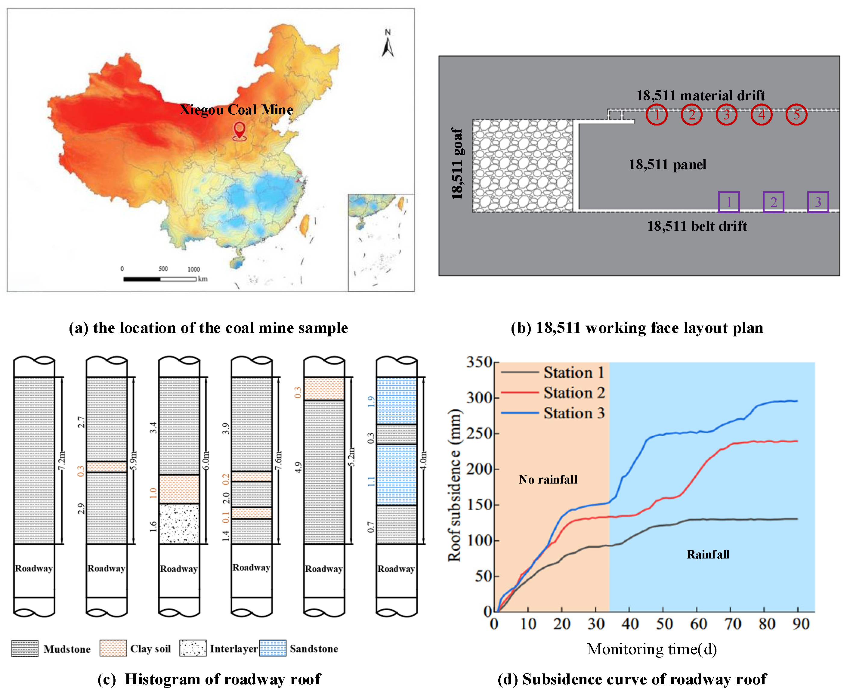
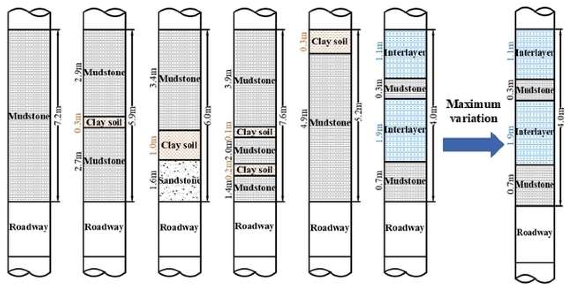
2. Engineering Background

According to China Coal Network data, total coal production reached 4.71 billion tons in 2023, representing a 3.4% year-on-year increase. Shanxi, Inner Mongolia, and Shaanxi Provinces account for 70% of total coal production, characterized by shallow-buried coal seams, abundant reserves, and superior coal quality. Shanxi Province, ranking first in annual coal production in China, faces challenges in certain areas due to shallow burial depths, significant roadway roof deformation, and frequent anchor rod and cable detachment [32]. It is important to note that the occurrence of mudstone–clay composite roofs in coal mines is not unique to China. Similar geological conditions have been reported in other coal-producing regions worldwide. For example, within the clay rock structure of the Maritsa East lignite basin in Bulgaria, all samples are composites [33]. These rock formations are prone to weathering and softening when exposed to water and humidity, leading to roof instability and deformation in underground coal mines. In Australia’s Bowen Basin, a major coal-producing region, the presence of weak clay layers within the roof strata has been identified as a significant challenge for maintaining roadway stability [34]. The clay layers, often associated with mudstone and siltstone, undergo swelling and softening when exposed to water, resulting in roof delamination and failure.
This study focuses on Xiegou Coal Mine of Shanxi Xishan Jinxing Energy Co., Ltd., located in Shuozhou, Shanxi Province, China. As a representative case, with its geographical location shown in Figure 1a. Figure 1b details the drilling sampling and roof deformation measurement area of the 18,511th working face in Xiegou Coal Mine. An exploration of the working face reveals shallow-buried coal seams with limited shale development on the inclined roof, predominantly composed of mudstone. In the RSR support system, the mudstone layer, being a difficult-to-control soft rock, is combined with the even clay layer to form a characteristic double soft composite roof. The exploration revealed that single or multiple layers of clay are distributed in different positions directly above, forming complex mudstone–clay structures. To analyze the clay distribution characteristics directly in the mudstone top, an on-site drilling exploration was conducted at positions ①–⑤ located 7–8 m above the material roadway as shown in Figure 1b. The detection results identified four categories of clay containing composite roof structures: ① a single mudstone structure; ② mudstone–clay composite structure; ③ mudstone–clay–mudstone combination structure; and ④ mudstone–clay composite structure with multiple clay layers, as illustrated in the bar chart in Figure 1c.
The working face’s direct water source originates from the overlying Shanxi Formation sandstone fissure aquifer. Due to the shallow coal seam’s burial and developed roof structure with weathered fissures, roof fissure water frequently gathers on roadways through surface excavation precipitation or shallow groundwater recharge. During the rainy season, this leads to increased dampness and moisture in the roadway roof. RSR deformation measurement stations were established at positions 1–3 along the belt roadway as shown in Figure 1b. The measurements, illustrated in Figure 1d, reveal roof deformations of 240 mm and 300 mm at measuring points 2 and 3, respectively. Particularly, measuring point 1 shows a deformation of 140 mm during the dry season. The significantly larger roof deformation during the rainy season poses increased challenges for roadway support.
Clay layers alter roof mechanical properties, change rock mass deformation and failure characteristics, and complicate roadway support requirements. Therefore, this study addresses these challenges through three main approaches: investigating the content and characteristics of hydrophilic substances in clay and mudstone at both microscopic and macroscopic levels, analyzing the deformation and failure factors of mudstone–clay double soft composite layers through orthogonal experiments, and proposing corresponding prevention and control measures.

3. Microscopic Experimental Study on Mudstone–Clay

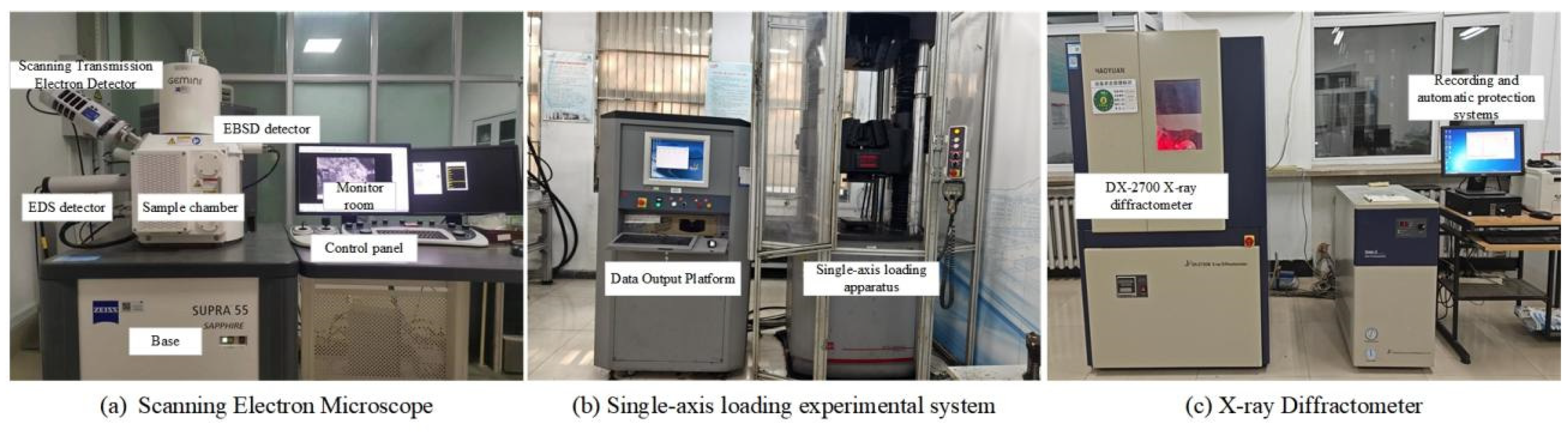
3.1. Experimental Methods

Experimental samples were collected through interval drilling at various locations along the material roadway of the 18,511th working face in Xiegou Coal Mine, Shanxi Xishan Jinxing Energy Co., Ltd. The samples were dried before testing. The experimental research system consists of a loading system, an X-ray diffractometer, and a SEM, as shown in Figure 2. For XRD analysis, dry rock samples were ground into powder (<30 mg diameter, >10 mg mass) and tested using an X-ray diffractometer (DX-2700B model) (Dandong Haoyuan Instrument Co., Ltd., Dandong City, Liaoning Province, China) to determine the material hydrophilic properties. The diffractometer was operated at 40 kV and 40 mA, with the measurement range of 2θ from 0° to 80° and a step size of 0.02°. The resulting diffraction patterns were analyzed using the X’Pert HighScore Plus 4.0 software and compared with the International Centre for Diffraction Data (ICDD) database to identify the mineral phases present in the samples. Microstructural features were observed using a high-resolution field emission SEM (Gemini SEM model). SEM analysis was conducted to investigate the microstructure and morphology of the mudstone and clay samples. Small pieces of the samples were mounted on aluminum stubs using carbon tape and coated with a thin layer of gold to enhance conductivity. Using the Hitachi S-4800 field emission scanning electron microscope produced by Suzhou Science Instrument Co., Ltd., Suzhou, China, the sample was examined under an accelerating voltage of 15 kV. High-resolution images were obtained at various magnifications to observe the surface features, pore structure, and particle arrangement of the samples. Macroscopic failure characteristics were analyzed through loading experiments using an electro-hydraulic servo-controlled rock mechanics test system (MTSC64.106), with displacement-controlled loading at 0.5 mm/min and 10 Hz collection frequency. The stress–strain curves, peak strength, and failure patterns were recorded and analyzed.

3.2. Analysis of Mudstone–Clay Experimental Results

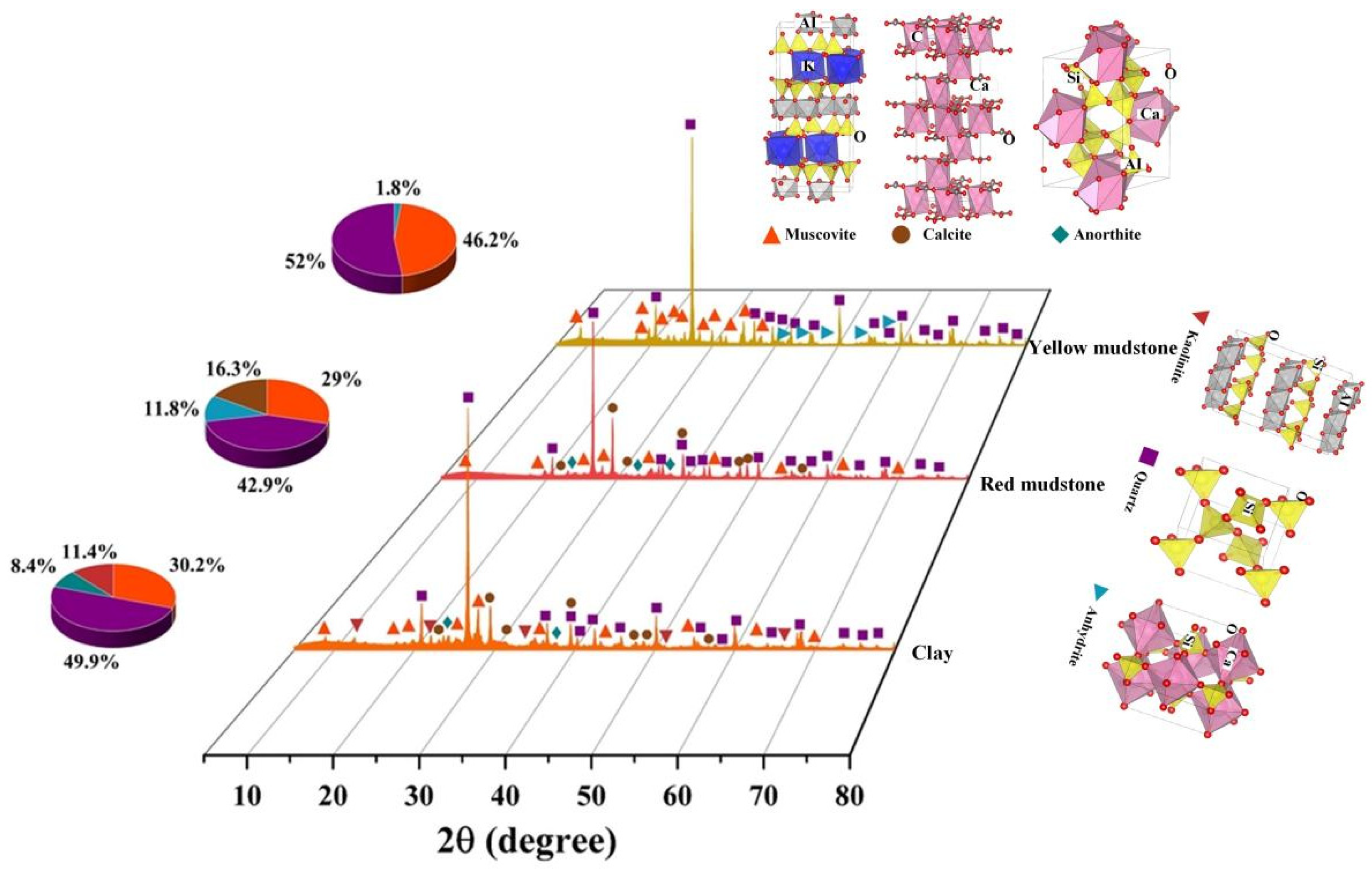
3.2.1. XRD Experimental Analysis

X-ray diffraction analysis of the layered mudstone–clay roof composition, which exhibits significant deformation during rainy seasons, revealed the following mineral contents and the crystal structures [35] (Figure 3): Red mudstone comprises 29% muscovite, 42.9% quartz, 11.8% anorthite, and 16.3% calcite. Clay samples contain 49.9% quartz, 30.2% muscovite, 11.4% kaolinite, and 8.4% anorthite. Yellow mudstone contains 52% quartz, 46.2% muscovite, and 1.8% hard gypsum. Among these minerals, muscovite, quartz, anorthite, and calcite demonstrate weak hydrophilicity with stable structures and minimal water reactivity. While anhydrite exhibits strong hydrophilicity, its low relative content minimally impacts roadway deformation. Kaolinite, a clay mineral containing hydroxyl groups, displays strong water absorption when dry and high plasticity upon water contact, though it resists swelling.

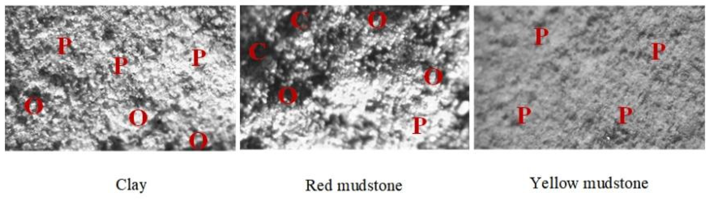
3.2.2. SEM Scanning Experimental Analysis

Scanning electron microscopy revealed detailed structural features of the sample, in which “P” denotes particles, “O” denotes pores, and “C” denotes cracks. As can be seen from Figure 4, at the microscopic level, red mudstone exhibits numerous cracks and impurity particles, while yellow mudstone contains fine particles in an independent state. At the microscopic level, clay blocks demonstrate abundant fine particles with poor interparticle bonding, inhibiting the formation a stable cohesive whole.
The presence of hydrophilic substances in clay, such as kaolinite, contributes to its strong plasticity and sensitivity to moisture changes. When exposed to water, these hydrophilic minerals can absorb moisture, leading to swelling, softening, and a reduction in the overall strength of the clay layer.
The mudstone’s microstructure, characterized by numerous fine particles with relatively weak particle bonding, also plays a crucial role in its mechanical properties. The weak bonding between particles suggests that the mudstone has a lower cohesive strength compared to rocks with stronger inter-particle bonds. This weak bonding can make the mudstone more susceptible to deformation and failure under stress, especially when combined with the presence of a moisture-sensitive clay layer. Therefore, it is necessary to analyze the mechanical properties of the influencing factors.

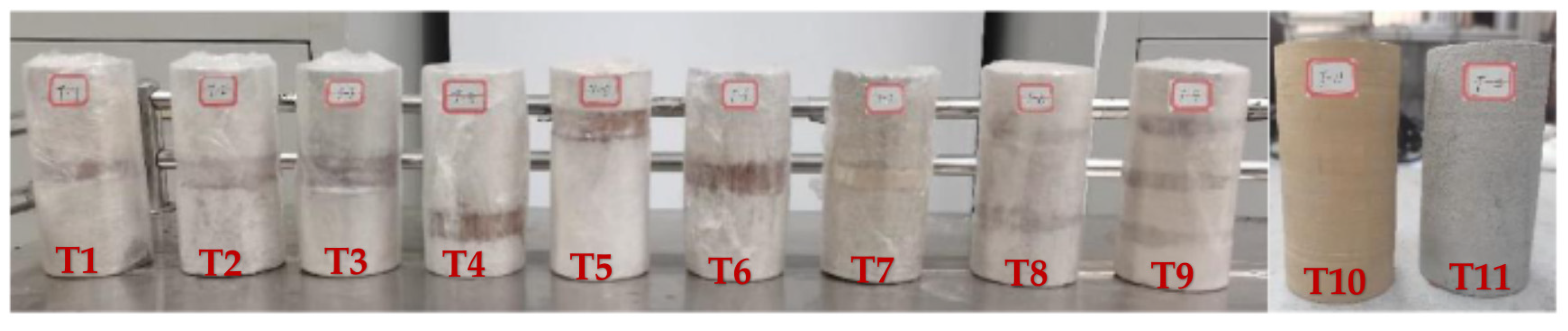
3.2.3. Uniaxial Compression Analysis

Mudstone used in the uniaxial loading experiment was extracted from the same large rock sample in the direct roof of the tailgate, while clay was obtained from the interlayer in the same borehole. In accordance with rock mechanics standards, samples were prepared as a standard cylinder (Φ50 mm × 100 mm), as shown in Figure 5. Non-parallelism at both ends of the specimen was <±0.05 mm, the end face was perpendicular to the specimen axis, and the axial deviation was <±0.25°. Four sets of experiments were conducted in triplicate based on the variable control principle. The composite specifications are listed in Table 1. To study the mechanical properties of mudstone–clay composites, composites T1, T2, and T3 were used to analyze the effect of clay layer thickness. Composites T2, T4, and T5 were used to analyze the influence of clay layer position. Composites T2, T6, and T7 were used to examine the effect of clay layer’s relative moisture content. Composites T1, T8, and T9 were used to analyze the impact of the clay layer number.
The stress–strain curves of mudstone–clay composites under varying clay layer thicknesses, depths, relative moisture contents, and numbers during loading were obtained from the uniaxial loading experiment, as shown in Figure 6. In Figure 6a, the uniaxial compressive strengths of mudstone–clay composites with clay thicknesses of 5 mm, 10 mm, and 15 mm are 1.88 MPa, 1.59 MPa, and 0.98 MPa, respectively. In composites with thicker clay layers, the initial loading stage is dominated by clay compaction and overflow effects, exhibiting significant plastic behavior. As the clay layer is compacted, the overall deformation is distributed between mudstone and clay. Compared to conventional composites, the stress–strain curve under uniaxial compression displays distinct abrupt and fluctuating characteristics.
From Figure 6b, in the pre-peak stage, the variation in clay layers shows limited impact on the stress–strain behavior of mudstone–clay composites, manifested by highly overlapping stress–strain curves. Compared to composites T2, the stress–strain curves of T4 and T5 under uniaxial compression exhibit distinct bimodal characteristics. Specifically, the mudstone thicknesses in T4 and T5 samples are 20 mm and 70 mm, respectively. The bimodal phenomenon in their stress–strain curves reflects the macroscopic failure of the mudstone layer. During compression, uneven deformation of saturated clay creates a non-uniform state on the clay layer’s upper surface, inducing significant shear effects on the upper mudstone. Notably, due to its thin upper mudstone layer (20 mm), the T5 sample exhibits weaker shear resistance. In the post-peak stage, the stress response of the T5 sample deviated from our expectations, and severe fracture occurred due to strong shear from uneven clay deformation. Additionally, when the thick mudstone layer experiences macroscopic damage, the entire mudstone–clay composite struggles to form an effective load-bearing structure, leading to more severe damage. This highlights the significant impact of shale layer thickness and shear performance on the composite’s mechanical behavior.
As shown in Figure 6c, with relative moisture contents of 0%, 50%, and 100%, the uniaxial compressive strengths of the mudstone–clay composites are 3.61 MPa, 1.00 MPa, and 1.59 MPa, respectively. Water exposure significantly reduces the uniaxial compressive strength, indicating increased deformation of the mudstone–clay composite roof during heavy rainfall. Compared to the dry clay combination, those with 50% and 100% moisture contents showed strength decreases of 72.30% and 55.96%, respectively. Notably, saturated clay composites exhibit slightly higher strength values than those with 50% moisture content, primarily due to the differences in clay mechanical properties under different moisture conditions. Additionally, as clay moisture content increases, the plastic-elastic properties of mudstone–clay composites become more pronounced in the pre-peak stage. The stress–strain curve of dry clay composites shows linear decline post-peak, while composites with 50% and 100% moisture contents display stepped decline. This suggests that water-exposed composites are more likely to form a load-bearing structure after macroscopic failure, experiencing periodic instability and rebalancing during loading.
From Figure 6d, the uniaxial compressive strength of mudstone–clay composites decreases linearly with increasing clay layer thickness. In the pre-peak stage, composites with different clay contents exhibit linear elastic behavior, with peak strain values that are similar, ranging from 0.030 to 0.034. Since mudstone serves as the primary load-bearing component, reduced mudstone thickness in multi-layer clay composites weakens the overall bearing capacity. This is particularly evident when comparing composites with equal total clay thickness but different layer configurations. For example, while the total clay layer thickness in T2 and T8 composites is 10 mm, their uniaxial compressive strengths are 1.59 MPa and 1.29 MPa, respectively. Similarly, for composites T3 and T9, with a total clay layer thickness of 15 mm, the uniaxial compressive strengths are 0.98 MPa and 0.76 MPa, respectively.
The uniaxial experiment results show that the stress–strain curve in the pre-peak stage changes nearly linearly, with the clay layer substantially affecting the uniaxial compressive strength of the composite specimen.

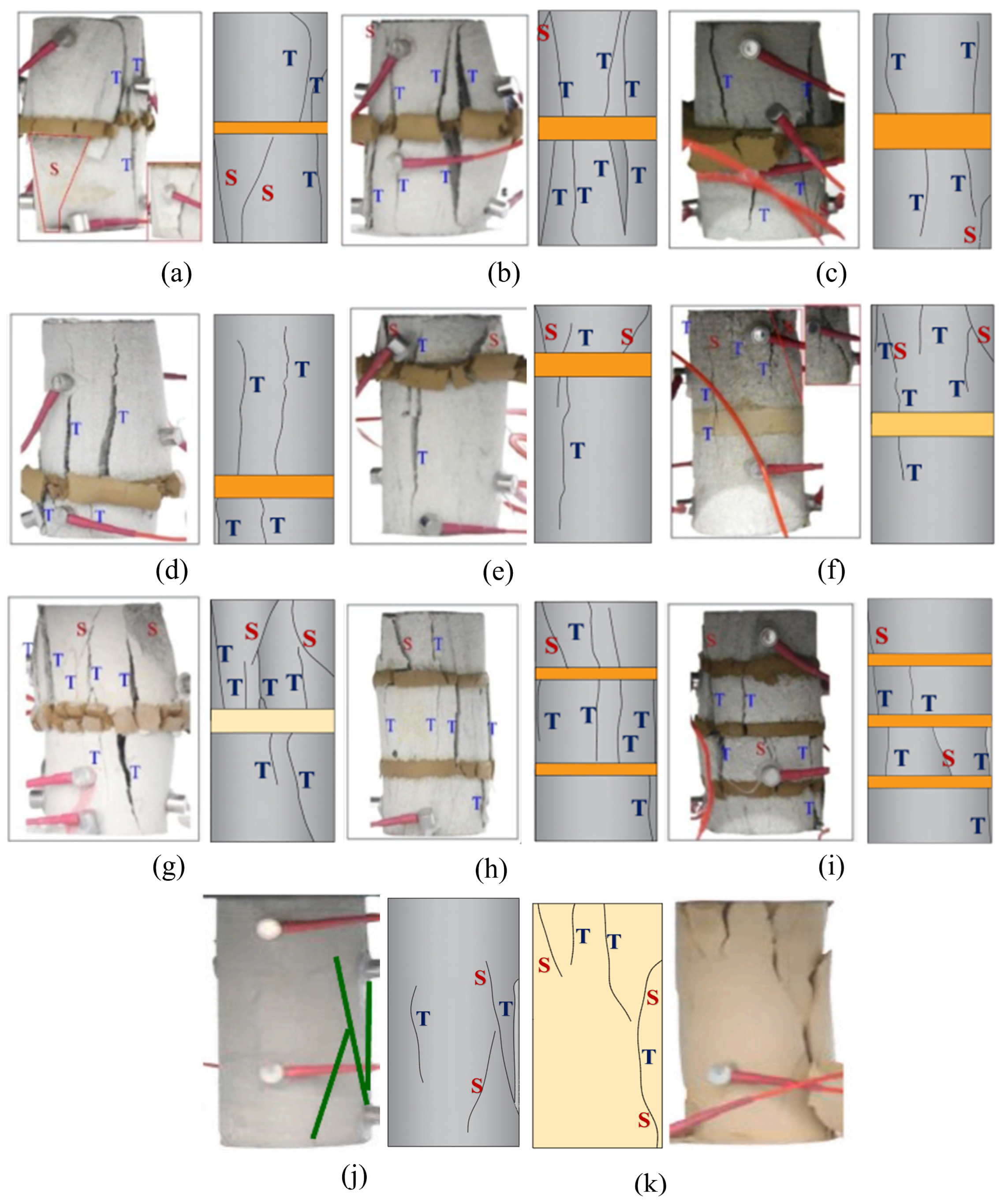
3.3. Failure Modes of Composites

Figure 7 illustrates the crack propagation stage during loading, with “T” representing tensile cracks and “S” representing shear cracks. The failure mode under uniaxial loading exhibits the following features. As clay layer thickness increases, the fracture mode shifts from tensile failure to shear failure, as shown in Figure 7a–c. At 5 mm clay thickness, fracture initiates and propagates in the clay layer. As loading continues, cracks penetrate into the mudstone, developing 1–2 tension cracks until macroscopic failure occurs. At 10 mm clay thickness, the clay layer fractures first, followed by initiation and expansion of mudstone fractures, with 2–3 tensile cracks forming. At 15 mm thickness, cracks in the clay layer expand rapidly, leading to both tensile and shear failures in the mudstone, with 3–4 cracks developing.
Figure 7b,d,e demonstrate that clay layer depth influences the failure mode while other variables remain constant. At 25 mm depth, the composite undergoes tensile failure from top to bottom without shear failure. At 50 mm depth, tensile cracks gradually expand, and shear failure appears at both ends. At 75 mm depth, shear failure occurs, and the fracture mode shifts from tensile to shear failure.
At 100% and 50% relative moisture contents, the composites show both tensile and shear failure, while at 0% moisture content, they primarily undergo single tensile failure. In dry conditions (0% moisture), cracks develop and propagate almost simultaneously in both clay and mudstone sections, exhibiting both tensile and shear cracks. At 50% moisture content, initial cracking occurs in the clay layer with tensile failure, followed by crack propagation, leading to overall tensile failure. At 100% moisture content, crack propagation is primarily tensile failure, as shown in Figure 7b,f,g.
With constant clay layer thickness and varying layer numbers, the failure behavior changes distinctly. In two-layer composites, the clay layer fails first, and cracks propagate through it before propagating into the mudstone. In this case, the middle mudstone experiences tensile failure, while the rocks at both ends undergo shear failure. In three-layer composites, tensile cracks increase in the central mudstone section, while rock cracks at the ends are less pronounced. Increased clay layer numbers promote tensile failure in the center mudstone and shear failure at the ends. More clay layers result in more macroscopic cracks and a more complex fracture morphology, as shown in Figure 7b,h,i.
During the uniaxial loading experiment, failure typically begins with cracking in the clay segment. As the clay layer is compacted, cracks gradually widen. Once tension cracks penetrate the clay, the mudstone ruptures as the clay overflows outward. With increasing axial load, tensile cracks in the mudstone grow in number, length, and width. When axial stress peaks, macroscopic damage occurs in the mudstone, with cracks extending toward the top and bottom of the composite. The clay’s bonding effect creates a stable triangular structure between rocks adjacent to the tensile crack. As pressure continues to rise, axial deformation increases, disrupting the balance of this triangular structure and further expanding the tensile cracks in the mudstone. The clay restricts lateral movement of the fractured rock mass, gradually increasing interfacial friction, which halts the expansion of tensile cracks after a certain distance. This results in the formation of a new triangular stable structure. This process repeats as tensile cracks advance toward the composite ends until the fractured rock mass collapses. This periodic disruption of triangular stability ultimately leads to composite failure.
The failure mode of mudstone–clay composites with water-bearing clay is primarily tensile failure, often characterized by penetrating cracks. During uniaxial loading, cracks initiate in clay layer first due to the lower strength and deformation resistance of water-bearing clay compared to mudstone. The cracks begin in the middle of the clay and propagate outward to the mudstone–clay interface. This indicates that clay’s outward extrusion after compaction, which creates a tearing effect on the mudstone, is the main mechanism causing tensile failure in the composite material.
Shear cracks in mudstone–clay composites are relatively sparse, with smaller crack lengths and openings compared to tensile cracks. Higher relative moisture content leads to more shear cracks. This occurs primarily because compacted clay cracks overflow outward under dry conditions. The central part of the mudstone–clay interface plane is elevated, causing uneven stress during uniaxial loading and resulting in shear cracks. These cracks are primarily located at the edges and corners of the mudstone, affect a limited area, and are closely linked to the horizontality of the composite interface. Therefore, tensile cracks caused by tensile failure significantly influence the stability of uniaxial loading experiments, while shear cracks have minimal impact on the bearing characteristics.

4. Deformation and Instability Law and Prevention Technology of Double Soft Composite Roof

In this study, macroscopic failure characteristics of rock composites were analyzed to explore how clay layer parameters affect RSR deformation and failure. Figure 8 presents the construction diagram of the model used in this study to investigate the influence of clay layer parameters on the deformation and failure of the roadway-surrounding rock (RSR). Table 2 is about Mechanical parameters of strata in FLAC3D model. The model geometry, including the roadway dimensions and the stratigraphic layers, was determined based on the geological conditions of the study area and the field measurements of the 18,511th working face in the Xiegou Coal Mine. The mudstone and clay layers were modeled using the Mohr–Coulomb constitutive model, with material properties derived from laboratory tests and calibrated using field data. The model boundary conditions were set to simulate the in situ stress state and the excavation process of the roadway.
Using an orthogonal experimental method, the sensitivity of clay layer thickness, moisture content, and layer depth to roadway roof subsidence was examined using FLAC3D 6.0 and SPSS 17.0 software [36]. A parametric study was conducted by varying the clay layer thickness, moisture content, and depth within the model. The roof subsidence and the deformation of the RSR were monitored at key locations within the model for each parameter combination. The numerical simulation results were then analyzed using SPSS software to determine the sensitivity of each parameter to the roadway stability and to identify the critical factors influencing the deformation and failure mechanisms of the mudstone–clay composite roof.

4.1. Orthogonal Experimental Analysis

4.1.1. Scheme Design

The orthogonal experiment, used to analyze the influence of multiple factors on experimental results, involves partial experiments rather than comprehensive ones to select representative test points [37,38]. Table 3 presents an orthogonal experimental design to examine the effects of clay layer thickness, moisture content, and position on roadway roof subsidence.
As the “layer” factor consists of seven levels, differing from the level numbers of other factors, a standard orthogonal table cannot be directly applied. The experimental design was therefore generated using SPSS software by inputting the factors and their corresponding levels into the orthogonal design interface. Table 4 is the orthogonal experimental table scheme design for the relevant experiments.

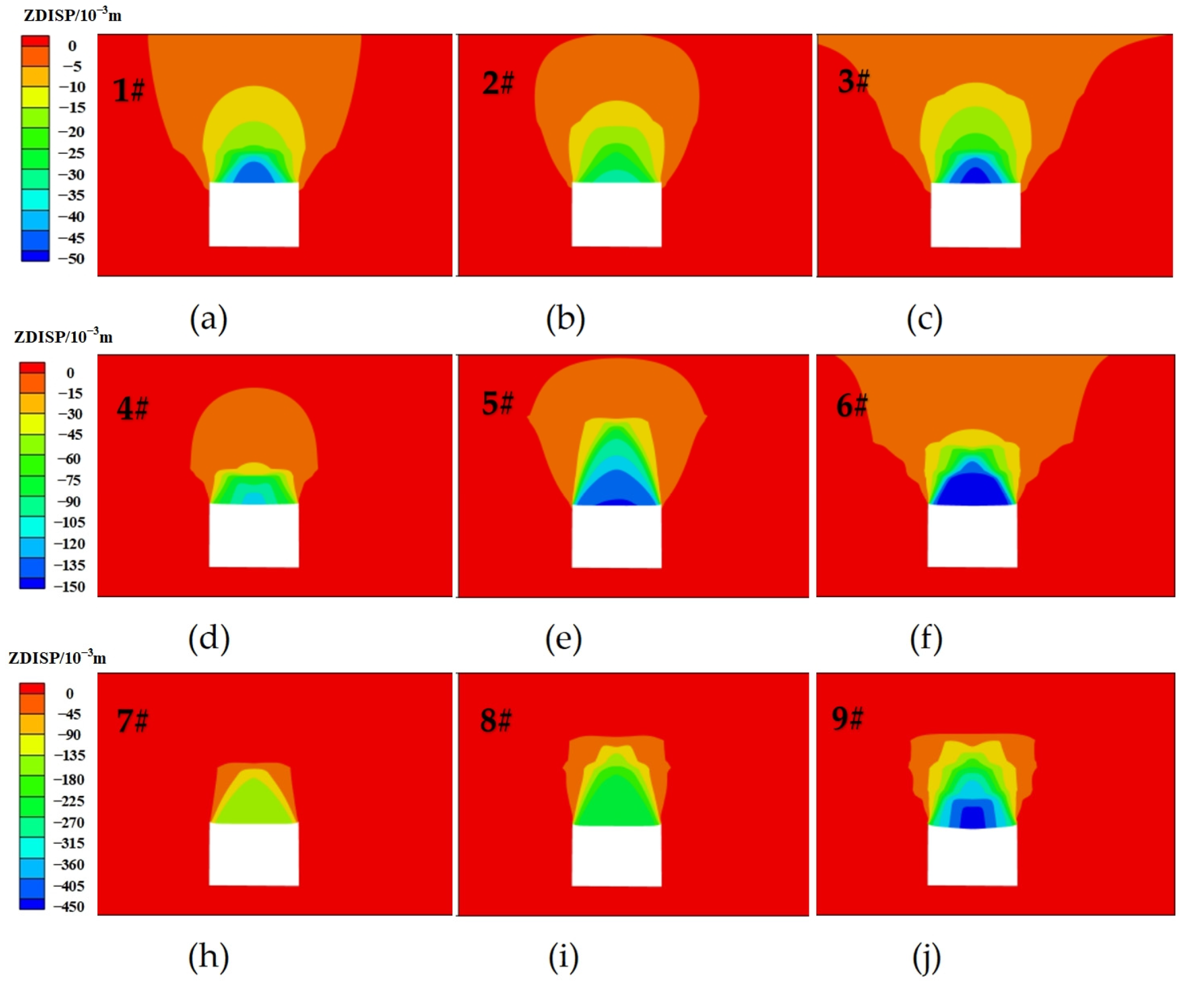
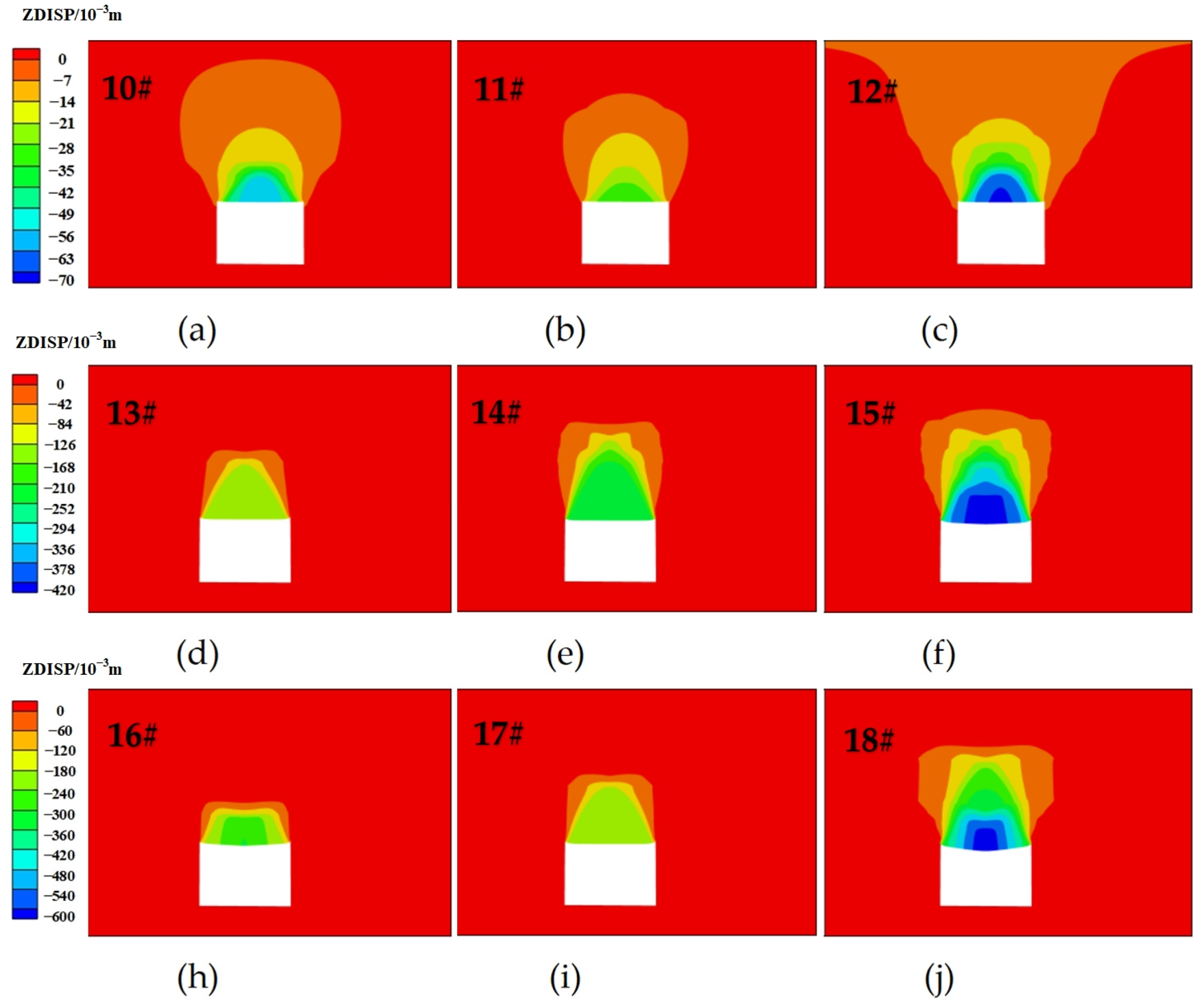
4.1.2. Simulation Results of Roof Migration

A numerical model was established based on the orthogonal experimental design, and FLAC3D was used for numerical simulation to determine roadway roof subsidence under different conditions. Based on the orthogonal experiment scheme in Table 4, data simulation was carried out. Figure 9, Figure 10 and Figure 11 show displacement simulation cloud maps for various factors.
Based on the experimental results, make a classification and comparison. In the Figure 9, Figure 10 and Figure 11, (a), (b), and (c) represent the samples of the test piece with the same moisture content of 0%; (d), (e), and (f) represent the relative water content of 50% in both cases, while (h), (i), and (j) indicate the relative water content of 100%.
Comparing schemes 1–3 in Figure 9, with the same layer thickness (0.4 m) and moisture content (0%), increased layer thickness leads to a larger deformation range of the roadway. Between schemes 1 and 4 (Figure 9), under the same layer thickness (0.4 m) and depth (1.5 m), roadway deformation increases with higher water content. Schemes 7–9 in Figure 9 demonstrate that roadway deformation increases with the number of layers under different layer conditions. Scheme 9 in Figure 9 shows a significant arc-shaped sinking, reaching a maximum deformation of 443.82 mm and exhibiting the largest variation range.
Figure 10 shows that with 0.8 m clay layer thickness, scheme 18 (relative moisture content of 100%, layer 1.5 + 4.5 m) displays substantial deformation with maximum roof displacement of 592.96 mm, showing the greatest variation under 0.8 m thickness. Figure 11 indicates at 1.2 m clay layer thickness, scheme 27 (relative moisture content of 100%, layer 1.5 + 3.0 m) shows the most significant deformation with symmetrical displacement characteristics reaching a maximum deformation of 1103.20 mm, the highest among all schemes. Overall, scheme 27 exhibits the most pronounced roadway deformation in the orthogonal experiment. The maximum roadway displacement variations are summarized in Table 5.

4.2. Sensitivity Analysis of Influencing Factors

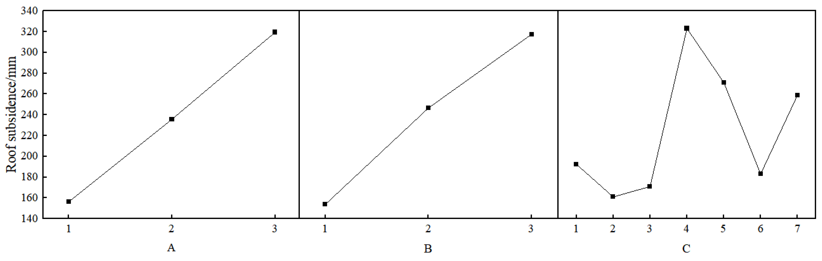
4.2.1. Orthogonal Experiment Range Analysis

Using the range analysis method, the experimental results from Table 6 were used to evaluate the influence and ranking of clay layer moisture content, thickness, and type on roof subsidence [39,40]. Following range analysis, variance analysis was conducted to verify the results and assess the reliability of parameter optimization.
(1) For roadway roof subsidence analysis, the K1 value for layer thickness is the sum of experimental results corresponding to the number “1” in that column as follows:
K1 = 1407.16
Therefore, K2 = 2121.27 and K3 = 2874.57. The average layer thickness is obtained by dividing K1 value for layer thickness by its corresponding horizontal repetition number as follows:
K 1 ¯ = 1407.16 9 = 156.35
Similarly, the average layer thickness is K 2 ¯ = 235.70 and K 3 ¯ = 319.40. A larger range (R) indicates a greater impact from factor level changes on the indicator, signifying the factor’s greater importance. Conversely, a smaller range suggests the factor is less significant [41,42]. Taking roadway roof subsidence as an example, the range for layer thickness is the difference between the maximum and minimum values of K 1 ¯ , K 2 ¯ , and K 3 ¯ , which equals R A = K 3 ¯ K 1 ¯ = 163.05 . Similarly, the K value K 3 ¯ , average K 1 ¯ , and range R for each factor affecting roadway roof subsidence can be determined, as shown in Table 4. The mean main effects for each factor are illustrated in Figure 12. In Figure 12, (A), (B), and (C) respectively represent the main effects of thickness, moisture content and layer position.
(2) Calculate the conversion value R of the range R. When factor levels are the same, the primary and secondary orders of factors are determined entirely by R. However, when factor levels differ, a coefficient is used to convert the range R for comparison. The conversion formula for the range is as follows:
R = d R r
In Equation (1), R is the extreme range of factors; r = n m is the number of repetitions for each factor level of the experiment; and d is the conversion coefficient determined by the number of factor levels, with values provided in Table 7.
(3) Calculate the primary and secondary orders of factors determining the size of R′. The conversion of roof subsidence R is as follows:
R A =   0.52   ×   163.05   ×   9 = 254.36
R B =   0.52   ×   330.38   ×   9 = 515.40
R C =   0.35   ×   308.80   ×   9 = 212.26
The converted range R′ values for roof subsidence indicate that the clay layer has the largest moisture content range, making it the primary factor. In contrast, clay layer thickness and layer range are relatively small, making them secondary factors.

4.2.2. Orthogonal Experiment’s Analysis of Variance

Analysis of variance is a practical and effective statistical method for examining the significance of factors influencing experimental results [43]. To account for errors in orthogonal experiments, Ki denotes the sum of data at the same level, while T represents the total sum of experimental data. Here, A is the number of horizontal repetitions and B is the total number of experimental data. The sum of squared deviations is calculated according to Equation (3).
S i 2 = i = 1 n K 1 2 A T 2 B
S i 2 represents the sum of squared deviations for the orthogonal i-th column of Table 4; C represents the sum of squared deviations of column I, with its degree of freedom fi as follows:
f i = C 1
In the absence of repeated experiments and repeated sampling, the relationships between the sum of squares of total deviation, the sum of squares of column deviations, the total degrees of freedom, and column degrees of freedom are as follows:
S T 2 = S i 2
S A 2 = S i 2
Equations (5) and (6) represent decomposition formulas for sum of squares and degrees of freedom in the orthogonal table, respectively. In the orthogonal experiment, if factor A is assigned to the i-th column, the sum of squared deviations for factor A equals that for the i-th column, denoted as S A 2 = S i 2 . A one-sided F-test is performed with random error variance as the denominator and factor variance as the numerator. The F calculation is as follows:
F i = S i 2 / f i S i 2 / f e
Comparing the obtained F value with the critical values (fi, f e ), if Fi ≥ (fi, f e ), the factor is considered to have a significant impact on the indicator. If Fi ≤ (fi, f e ), the factor is considered not significant. This variance analysis applies to non-repeated experiments, but the method for repeated experiments is essentially similar, differing only in error estimation complexity. D represents the number of repetitions for each experiment, and the formula for calculating the sum of squared deviations for each column is as follows:
S i 2 = i = 1 n K 1 2 A × D T 2 B
In repeated experiments, the total experimental error is divided into two parts: column error (denoted as S e 1 2 ) and repeated experimental error (denoted as S e 2 2 ). The sum of the squared height differences of the total experimental error is S e 2 .
S e 2 = S e 1 2 + S e 2 2
where S e 2 2 is calculated as follows:
S e 2 2 = i = 1 n j = 1 m ( y i j y i ¯ ) 2 = i = 1 n j = 1 m y i j 2 1 m i = 1 n ( j = 1 m y i j ) 2
where n is the number of rows in the orthogonal table, m represents the number of repetitions for each experimental condition, and yij denotes the corresponding experimental data. The degrees of freedom are as follows:
f e 2 = n ( m 1 )
Using variance analysis principles and orthogonal experimental results, significance analysis was performed on the numerical simulation results for roadway roof subsidence. Variance analysis results for roof subsidence are shown in Table 8.
The p-value in Table 8 measures the difference between the control and experimental groups. Significance levels indicate judgments based on corresponding critical value tables with varying degrees of certainty. For a certain factor A, when a = 0.05, if p < a, there is a confidence level of (1 − a) × 100%, that is, a 95% confidence that factor A is significant. Conversely, if p > a, factor A cannot be considered significant at the a level [44]. Generally, if a = 0.05 and p < a, factor A is significant; if a = 0.01 and p < a, factor A is highly significant. The significance criteria are shown in Table 9.
Based on Table 9, the influence of various factors on the roof subsidence of the tunnel can be determined. Among them, the p-value of the water content in the clay layer is 0.000, which is less than 0.01, indicating that the water content is a level I factor, and its influence on the roof subsidence is highly significant. The p-value for the thickness and position of the clay layer is greater than 0.05, which indicates that thickness and position are level III factors, and their influence on the roof subsidence is not significant.
These findings are consistent with some previous studies, while also offering new insights. For example, researchers have investigated the effect of water content on the mechanical properties of clay-bearing sandstone and found that increasing water content significantly reduced the rock strength and increased deformation [45]. However, this study focused on a single rock type and did not consider the influence of clay layer thickness or position in a composite roof system. In another study, the deformation behavior of a composite roof consisting of mudstone and coal layers was studied using numerical simulations [46]. They found that the thickness of the weak coal layer had a significant impact on roof subsidence, with thicker coal layers leading to greater deformation. But this study did not consider the effect of moisture content or the presence of clay layers.
The current study extends these previous findings by investigating the combined effects of moisture content, clay layer thickness, and position in a mudstone–clay composite roof system. The moisture content is identified as the dominant factor influencing roof subsidence, even more significant than the thickness and position of the clay layer. The sensitivity analysis in this study highlights the importance of considering the interactions between different factors in composite roof systems. While previous studies have often focused on individual factors in isolation, this work demonstrates that the relative significance of each factor can vary depending on the specific combination of geological and environmental conditions. In summary, the sensitivity analysis results in this study offer a new perspective on the factors influencing roof subsidence in mudstone–clay composite roofs. By comparing these findings with previous research and highlighting novel contributions, this manuscript provides a clearer understanding of the significance and implications of the current work in the field of coal mine roadway support design.

4.3. Prevention Techniques for Roadway Deformation

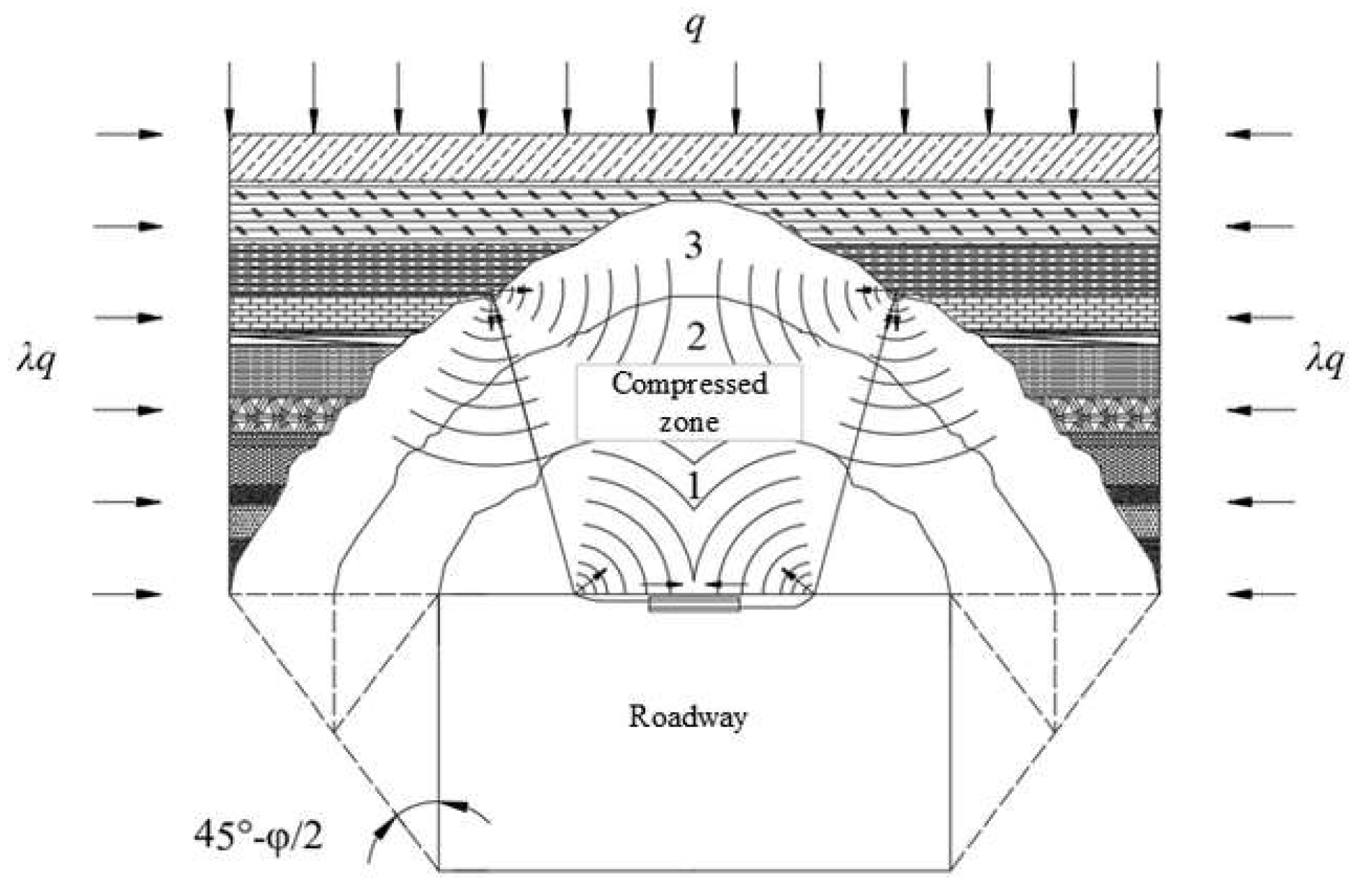
4.3.1. Principle of Roof Support Prevention and Control

The relative moisture content from the above orthogonal test is the main sensitivity factor. Figure 13 displays a geological survey of the 18,511th working face of the material roadway, which indicates that higher moisture content and thicker clay interlayers, compared to other borehole surveys, result in greater deformation of the roadway roof. Therefore, a roadway support design is developed.
The mudstone–clay composite rock layer has multiple layers, which have a significant impact on the anchoring effect of anchor rods/cables. Using numerical analysis methods, we explore the stress distribution in the roof with multiple support configurations of anchor rod–short anchor cable–long anchor cable, as shown in Figure 14.
Using combined support of anchor rods and short anchor cables increases the bearing area above the roadway. This combination generates stress superposition extending to the anchoring end of the short anchor cable, enhancing overall bearing performance. When incorporating long anchor cables with anchor rods and short anchor cables, the main bearing expands substantially. The combined action of the anchor rods and long and short anchor cables creates stress superposition, extending the bearing area towards the depth of the overlying rock and penetrating the anchoring end of the anchor cable. This enlarged bearing area forms a more effective support structure for the mudstone–clay composite roof.
The support mechanism operates as follows: (1) A non-ribbed prestressed anchor rod is installed on the roadway roof, creating compressive stress zones at both ends (Figure 15). (2) Installation of prestressed short anchor cables forms a compressive stress zone in the middle rock layer of the roof. This enhances the self-supporting ability of the middle layer, promotes the downward movement of the composite roof’s “neutral axis”, and increases the bending resistance of the roof rock layer. Truss anchor cables simultaneously apply horizontal pressure to the overlying rock, improving the integrity of the soft and fractured roof (Figure 16). (3) The combination of supporting anchor rods and short anchor cables in the lower roof’s surrounding rock creates a double-layer reinforced arch, effectively enhancing the roadway roof’s stability. Long anchor cables installed in the overlying rock further tighten the double-layer arch, forming a multi-layer stress superposition structure (Figure 17). In the Figure 15, Figure 16 and Figure 17, the 1, 2 and 3 respectively represent the range of the natural balance arch, the invisible balance arch and the expanded invisible balance arch.

4.3.2. Design of Roof Support Parameters

The composite roof at Xiegou Coal Mine exhibits thick mudstone–clay layer with low strength level, looseness, fragility, poor stability, and easy detachment after roadway excavation. Based on these conditions, the following support criteria and strategies are proposed:
First, adopt a “low–medium–high” multiple support method and address long anchor drilling difficulties through joint support.
Second, apply initial support using anchor rods, steel mesh, and short anchor cables to prevent delamination of low to medium composite roof, and using long anchor cables to control high-level rock layer stability.
Third, install long anchor cables at a specified distance behind the excavation face after roof water drainage.
Fourth, enhance support strength and initial prestress of anchor rods, short anchor cables, and long anchor cables, with long anchor cables supported by truss anchor cables.
Based on geological conditions in the material roadway of the 18,511th working face at Xiegou Coal Mine, with the roadway dimensions of 5 m width and 3.6 m height, support parameters were determined using the stress superposition principle. As stability control is needed for natural balance arches, invisible balance arches, and extended invisible balance arches, the following specifications were established: roof anchor rods should be 2.1 m–3.5 m in length with spacing under 1.5 m × 1.5 m; short anchor cables should be 3.5 m–4.1 m in length with spacing under 2.5 m × 2.5 m; and long anchor cables should exceed 4.1 m with row spacing less than 3 m × 3 m.
Therefore, the designed parameters for anchor rod and cable support are as follows: (1) roof anchor rod: 2.6 m length with row spacing less than 1 m × 1 m; (2) short anchor cable: 4 m length with row spacing less than 2 m × 2 m; and (3) long anchor cable: 5.5 m length with row spacing less than 2.85 m × 2 m. The final roadway support design is shown in Figure 18.

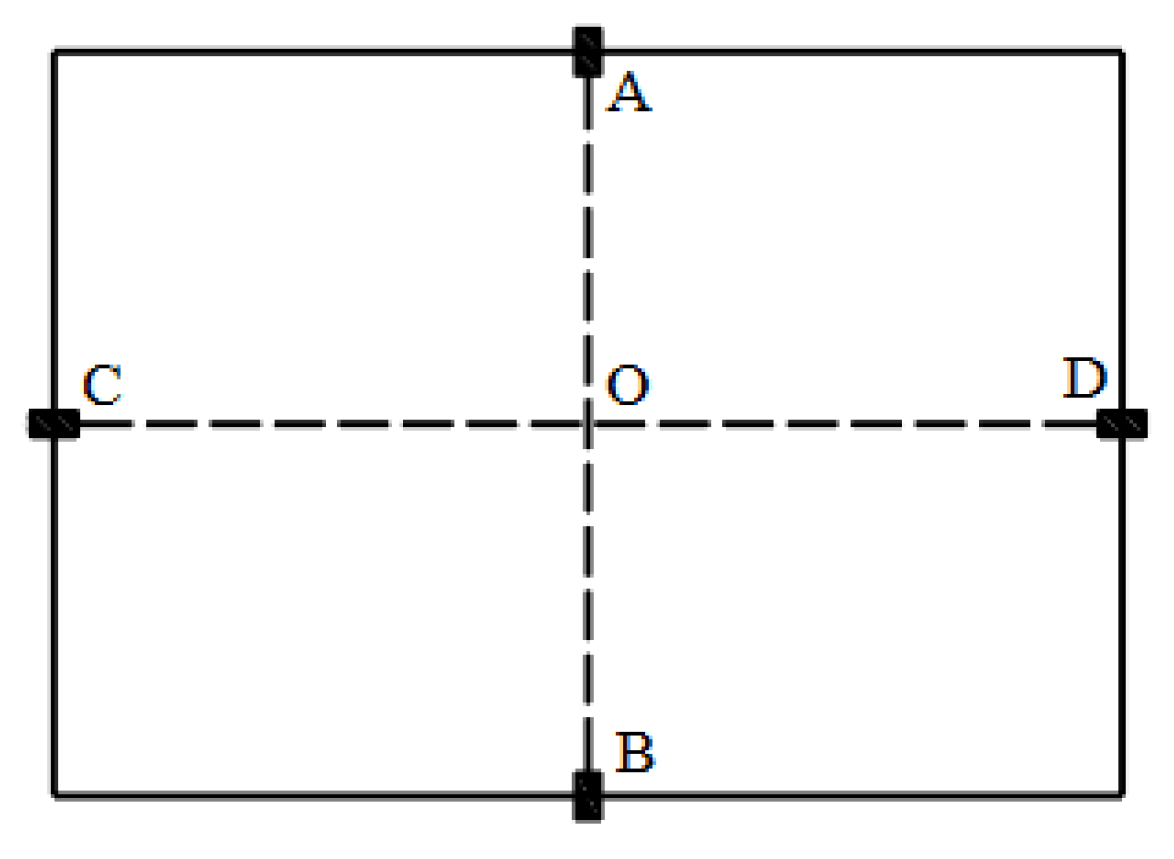
4.3.3. Analysis of Engineering Site Effects

To analyze deformation patterns in surface and deep RSR, assess the support body’s stress state, and identify abnormal deformation areas in the roadway, convergence monitoring was conducted on the experimental section’s roadway surface. Displacement measurement stations were arranged near the excavation face, with each station containing two observation sections spaced 2 m apart and three measurement stations in total. Monitoring was performed using the “cross measurement method”, as shown in Figure 19. In Figure 19, ‘A’, ‘B’, ‘C’ and ‘D’ represent the measurement points on the roof and floor of the roadway as well as on the left and right sides.
The displacement observations for both sides and the top and bottom plates of the 18,511th working face of the material roadway are shown in Figure 20. The roadway surface deformation during excavation, when supported by anchor rods and short anchor cables, exhibits the following patterns:
(1)
Initial Excavation Impact Stage
This stage occurs within 5 days after excavation, or within 10 m of the excavation face. Following roadway excavation, stress redistribution in the RSR creates stress concentration around the roadway, peaking in the shallow part and causing crack expansion in the shallow RSR. The low-strength mudstone–clay composite rock layer yields and enters a plastic state, resulting in significant shallow rock deformation. At this point, deformation rates are high for the roadway roof, floor, and sides. Monitoring shows that roof and floor deformation rates reach a maximum of 37 mm/d with 92 mm cumulative displacement, while side deformation rates peak at 32 mm/d with 73 mm cumulative displacement.
(2)
Excavation General Impact Stage
This stage spans from 5 to 15 days after excavation, occurring 10 m–30 m from the excavation face. The plastic zone formed in the shallow mudstone–clay rock layer above the roadway and the coal bodies during initial excavation altered the stress state in the RSR, with stress concentration moving deeper. This results in decreased stress concentration, reduces support load, and improves the surrounding rock’s stress state. During this period, deformation rates significantly decrease, with side convergence rates dropping from 32 mm/d to 4 mm/d, and the roof and floor’s convergence rates decreasing from 37 mm/d to below 5 mm/d. The roof and floor maintain higher convergence rates and greater cumulative displacement compared to the sides.
(3)
Excavation Affects Stability Stage
After 15 days of roadway excavation, with the excavation face more than 30 m away, secondary reinforcement supports with long anchor cables were implemented on the roof. This combined support system of anchor rods, short anchor cables, and long anchor cables effectively controlled roadway deformation. The surrounding rock entered a stable stage, with deformation rates stabilizing at 23 mm/d. Excavation activities had minimal impact on roadway stability at this stage. Final measurements showed cumulative deformations of 141 mm for the roof and floor and 135 mm for the two sides. The stabilization of surrounding rock after 15 days and at 30 m of excavation demonstrates the effectiveness of the integrated support system in controlling deformation of the mudstone–clay composite roof roadway.

5. Conclusions

  • The inherent structure of mudstone and clay features extensive cracks and pores, with relatively independent particles, facilitating water infiltration. The high content of kaolin in clay, characterized by strong hydrophilicity and plasticity, significantly influences roadway roof stability and subsidence behavior;
  • Uniaxial compressive strength tests demonstrated that the moisture content of the clay layer greatly influences the mechanical properties and failure behavior of the composite roof. Saturated clay composites exhibited lower strength and predominantly tensile failure compared to dry clay composites;
  • The distance between the clay layer and roadway roof shows a negative correlation with the maximum roof subsidence. The clay layer’s thickness is positively correlated with the roof subsidence—thicker layers lead to a greater maximum subsidence. An increase in the number of clay layers results in an overall greater subsidence. The relative moisture content in the clay layer is most sensitive to the roadway roof stability, followed by the thickness and number of clay layers;
  • The combined support system of anchor rods, short anchor cables, and long anchor cables creates a stress superposition in the surrounding rock. This integrated approach expands the bearing area above the roadway, allowing a larger rock mass to share the load, thereby ensuring the safety of the surrounding rock in the mudstone–clay composite roof coal roadway.
This paper has outlined extensive research on a composite roof of mudstone and clay, and its supportive effect is remarkable. However, at present, the issues of economic costs and automated monitoring systems have not been taken into consideration. It is believed that in the future, a complete set of detection systems can be developed to conduct real-time monitoring of roofs.

Author Contributions

Conceptualization, K.S. and H.L.; methodology, K.S. and J.Y.; software, H.L.; validation, C.L. and J.W.; formal analysis, J.Y.; investigation, J.W.; resources, C.L.; data curation, J.W.; writing—original draft preparation, K.S.; writing—review and editing, K.S. and H.L.; visualization, H.L.; supervision, C.L.; project administration, C.L.; funding acquisition, K.S. All authors have read and agreed to the published version of the manuscript.

Funding

This research received no external funding.

Institutional Review Board Statement

Not applicable.

Informed Consent Statement

Not applicable.

Data Availability Statement

The data presented in this study are available in article.

Conflicts of Interest

The authors declare no conflicts of interest.

Abbreviations

The following abbreviations are used in this manuscript:
XRDX-ray diffraction
PSPMultidisciplinary Digital Publishing Institute
SEMScanning Electron Microscope

References

  1. Wang, Z.; Wang, M.; Zhou, L.; Zhu, Z.; Shu, Y.; Peng, T. Research on uniaxial compression strength and failure properties of stratified rock mass. Theor. Appl. Fract. Mech. 2022, 121, 103499. [Google Scholar] [CrossRef]
  2. Chen, J.; Liu, W.; Chen, L.; Luo, Y.; Li, Y.; Gao, H.; Zhong, D. Failure mechanisms and modes of tunnels in monoclinic and soft-hard interbedded rocks: A case study. KSCE J. Civ. Eng. 2020, 24, 1357–1373. [Google Scholar] [CrossRef]
  3. Duffaut, P. Structural weaknesses in rocks and rock masses tentative classification and behaviour. In Proceedings of the ISRM International Symposium, International Society for Rock Mechanics, Tokyo, Japan, 21–24 September 1981; pp. 93–97. [Google Scholar]
  4. Liu, Y.; Zheng, P.; Xu, L.; Li, W.; Sun, Y.; Sun, W.; Yuan, Z. Mechanism of roof deformation and support optimization of deeply buried roadway under mining conditions. Appl. Sci. 2022, 12, 12090. [Google Scholar] [CrossRef]
  5. Duan, S.Q.; Jiang, Q.; Liu, G.F.; Jie, C.X.; Gao, P.; Xu, D.; Li, M. An insight into the excavation-induced stress paths on mechanical response of weak interlayer zone in underground cavern under high geostress. Rock Mech. Rock Eng. 2021, 54, 1331–1354. [Google Scholar] [CrossRef]
  6. Duan, S.; Jiang, Q.; Xu, D.; Liu, G. Experimental study of mechanical behavior of interlayer staggered zone under cyclic loading and unloading condition. Int. J. Geomech. 2020, 20, 04019187. [Google Scholar] [CrossRef]
  7. Duan, S.Q.; Feng, X.T.; Jiang, Q.; Liu, G.; Pei, S.; Fan, L. In situ observation of failure mechanisms controlled by rock masses with weak interlayer zones in large underground cavern excavations under high geostress. Rock Mech. Rock Eng. 2017, 50, 2465–2493. [Google Scholar] [CrossRef]
  8. Wang, Y.; Pu, Z.; Ge, Q.; Liu, J. Study on the water-richness law and zoning assessment of mine water-bearing aquifers based on sedimentary characteristics. Sci. Rep. 2022, 12, 14107. [Google Scholar] [CrossRef]
  9. Wang, Y.; Li, M. Research on the deformation law of jointed surrounding rock during tunnel excavation based on hydromechanical coupling. Geofluids 2021, 2021, 5583940. [Google Scholar] [CrossRef]
  10. Kuforiji, H.I.; Olurin, O.T.; Akinyemi, O.D.; Idowu, O.A. Wave velocity variation with temperature: Influential properties of temperature coefficient (∂V/∂T) of selected rocks. Environ. Earth Sci. 2021, 80, 638. [Google Scholar] [CrossRef]
  11. Gautam, T.P.; Shakoor, A. Slaking behavior of clay-bearing rocks during a one-year exposure to natural climatic conditions. Eng. Geol. 2013, 166, 17–25. [Google Scholar] [CrossRef]
  12. Xu, J.; Kang, Y.; Wang, X.; Feng, G.; Wang, Z. Dynamic characteristics and safety criterion of deep rock mine opening under blast loading. Int. J. Rock Mech. Min. Sci. 2019, 119, 156–167. [Google Scholar] [CrossRef]
  13. Chen, S.; Qiao, C.; Yang, Z.; Qiao, C. Application of stochastic joint network simulation to composite strata of shallow-buried long-span metro tunnels. Bull. Eng. Geol. Environ. 2020, 79, 2085–2107. [Google Scholar] [CrossRef]
  14. Liu, X.; Li, Y.; Li, S.; Zhou, Y. Research on the disintegration characteristics of carbonaceous mudstone and properties of modified materials. Adv. Civ. Eng. 2019, 2019, 4382054. [Google Scholar] [CrossRef]
  15. Zeng, L.; Yu, H.C.; Qiu, J.; Luo, J.; Liu, J.; Gao, Q.; Zhang, H. Pore characteristics and microscopic damage mechanism of disintegrated carbonaceous mudstone exposed to dry-wet cycles. Constr. Build. Mater. 2024, 433, 136774. [Google Scholar] [CrossRef]
  16. Chen, C.; Fu, H.; Gao, Q.F.; Zeng, L.; Jia, C. Polyurea reinforcement of disintegrated mudstone embankments and the underlying mechanism. Transp. Geotech. 2022, 37, 100874. [Google Scholar] [CrossRef]
  17. Gao, Q.; Shi, Z.; Luo, J.; Liu, J. Microstructural insight into permeability and water retention property of compacted binary silty clay. J. Cent. South Univ. 2020, 27, 2068–2081. [Google Scholar] [CrossRef]
  18. Liu, W.; Tang, X.; Yang, Q.; Li, W. Influence of drying/wetting cycles on the mechanical cyclic behaviours of silty clay. Eur. J. Environ. Civ. Eng. 2015, 19, 867–883. [Google Scholar] [CrossRef]
  19. Li, Y.; Yang, R.; Fang, S.; Lin, H.; Lu, S.; Zhu, Y.; Wang, M. Failure analysis and control measures of deep roadway with composite roof: A case study. Int. J. Coal Sci. Technol. 2022, 9, 2. [Google Scholar] [CrossRef]
  20. Zhao, M.; Yang, R.; Fang, J. Stability and control technology for coal roadway of composite roof with thin-layered and argillaceous. J. Compos. Adv. Mater./Rev. Compos. Matériaux Avancés 2018, 28, 239. [Google Scholar]
  21. Wang, P.; Zhang, N.; Kan, J.; Xu, X.; Cui, G. Instability mode and control technology of surrounding rock in composite roof coal roadway under multiple dynamic pressure disturbances. Geofluids 2022, 2022, 8694325. [Google Scholar] [CrossRef]
  22. Shi, L.; Zhou, H.; Song, M.; Lu, J.; Liu, Z. Geomechanical model test for analysis of surrounding rock behaviours in composite strata. J. Rock Mech. Geotech. Eng. 2021, 13, 774–786. [Google Scholar] [CrossRef]
  23. Wang, Z.; Wang, Y.; Liu, Q.; Dino, G.; Ruan, Z.; Wu, A. Impact of weak interlayer characteristics on the mechanical behavior and failure modes of cemented tailings backfill: A study on thickness, strength, and dip angle. Eng. Fail. Anal. 2024, 165, 108795. [Google Scholar] [CrossRef]
  24. Zhao, H.; Deng, B.; Zhang, D.; Li, M.; Song, Z. Influence of weak interlayer thickness on mechanical response and failure behavior of rock under true triaxial stress condition. Eng. Fail. Anal. 2024, 162, 108419. [Google Scholar] [CrossRef]
  25. Liu, H.; Liu, C.; Yue, X.; Wang, J. Study on mechanical properties and acoustic emission characteristics of mudstone-clay composites under uniaxial compression. Eng. Geol. 2024, 332, 107478. [Google Scholar] [CrossRef]
  26. Zheng, W.; Guo, Y.; Zhi, G.; Bao, X.; Sun, M.; Ren, R.; Duan, Z.; Gao, Z. Stability Analysis and Control Measures of Large-Span Open-Off Cut with Argillaceous Cemented Sandstone Layered Roof. Math. Probl. Eng. 2021, 2021, 8744081. [Google Scholar] [CrossRef]
  27. Sun, B.; Mei, Y.; Li, W.; Shao, X.; Li, T.; Li, W.; Zhao, W.; Wang, L. Experimental study on the deformation and failure mode of surrounding rocks of a tunnel in a jointed rock mass. Eng. Fail. Anal. 2024, 163, 108470. [Google Scholar] [CrossRef]
  28. Zhang, H.; Li, Y.; Wang, X.; Yu, S.; Wang, Y. Study on stability control mechanism of deep soft rock roadway and active support technology of bolt-grouting flexible bolt. Minerals 2023, 13, 409. [Google Scholar] [CrossRef]
  29. Liu, C.; Li, Y. Predicting the shear resistance contribution of passive fully grouted bolts to jointed rock. Int. J. Geomech. 2020, 20, 04019174. [Google Scholar] [CrossRef]
  30. Chen, Y.; Li, Q.; Pu, H.; Wu, P.; Chen, L.; Qian, D.; Shi, X.; Zhang, K.; Mao, X. Modeling and simulation of deformation mechanism of soft rock roadway considering the mine water. Geofluids 2020, 2020, 8812470. [Google Scholar] [CrossRef]
  31. Zang, C.W.; Chen, Y.; Chen, M.; Zhu, H.; Qu, C.; Zhou, J. Research on deformation characteristics and control technology of soft rock roadway under dynamic disturbance. Shock. Vib. 2021, 2021, 6625233. [Google Scholar] [CrossRef]
  32. Bai, X.; Ding, H.; Lian, J.; Ma, D.; Yang, X.; Sun, N.; Xue, W.; Chang, Y. Coal production in China: Past, present, and future projections. Int. Geol. Rev. 2017, 1301226, 535–547. [Google Scholar]
  33. Yossifova, M.G.; Dimitrova, D.A.; Ivanova, R.I. Mineral and chemical composition of some claystones from the Troyanovo-3 mine, Maritsa East lignite basin, Bulgaria. Int. J. Coal Geol. 2018, 196, 93–105. [Google Scholar] [CrossRef]
  34. Seedsman, R. Application of the Brittle Failure Criterion to the Design of Roof Support in The Soft Rocks of Coal Mines. In Proceedings of the 11th Underground Coal Operators’ Conference, Wollongong, Australia, 10–11 February 2011; pp. 60–72. [Google Scholar]
  35. Downs, R.T.; Hall-Wallace, M. The American Mineralogist crystal structure database. Am. Mineral. 2003, 88, 247–250. [Google Scholar]
  36. Li, Y.; She, L.; Wen, L.; Zhang, Q. Sensitivity analysis of drilling parameters in rock rotary drilling process based on orthogonal test method. Eng. Geol. 2020, 270, 105576. [Google Scholar] [CrossRef]
  37. Yan, G.; Zheng, Y.; Wang, L.; Huang, Z. Optimization of stamping process parameters based on orthogonal test and intelligent algorithm. In Proceedings of the 2020 3rd World Conference on Mechanical Engineering and Intelligent Manufacturing (WCMEIM), Shanghai, China, 4–6 December 2020; pp. 393–397. [Google Scholar]
  38. Jiang, B.; Xia, W.; Wu, T.; Liang, J. The optimum proportion of hygroscopic properties of modified soil composites based on orthogonal test method. J. Clean. Prod. 2021, 278, 123828. [Google Scholar] [CrossRef]
  39. Xiang, H.; Lei, B.; Li, Z.; Zhao, K.; Lv, Q.; Zhang, Q.; Geng, Y. Analysis of parameter sensitivity of induction coil launcher based on orthogonal experimental method. IEEE Trans. Plasma Sci. 2015, 43, 1198–1202. [Google Scholar] [CrossRef]
  40. He, Q.S.; Liu, X.N.; Xiao, S.F. Application of orthogonal experimental design on reliability and sensitivity analysis. Adv. Mater. Res. 2011, 211, 651–655. [Google Scholar] [CrossRef]
  41. Wen, C.; Jia, S.; Fu, X.; Meng, L.; Zhao, Z. Experimental research and sensitivity analysis of mudstone similar materials based on orthogonal design. Adv. Mater. Sci. Eng. 2020, 2020, 2031276. [Google Scholar] [CrossRef]
  42. Liu, J.; Wang, Q.; Zhao, H.; Chen, J.; Qiu, Y.; Duan, D. Optimization design of the stratospheric airship’s power system based on the methodology of orthogonal experiment. J. Zhejiang Univ. Sci. A 2013, 14, 38–46. [Google Scholar] [CrossRef]
  43. Sun, D.; Liu, W.; Li, Z.; Zhan, X.; Dai, Q.; Xue, X.; Song, S. Numerical Experiment and Optimized Design of Pipeline Spraying On-Line Pesticide Mixing Apparatus Based on CFD Orthogonal Experiment. Agronomy 2022, 12, 1059. [Google Scholar] [CrossRef]
  44. Yang, W.; Meng, F.; Wu, D. Parametric Sensitivity Analysis and Efficiency Improvement of Electromagnetic Repulsion Mechanism Based on Orthogonal Experiment Design. In Proceedings of the IEEE International Magnetic Conference-Short Papers (INTERMAG Short Papers), Rio de Janeiro, Brazil, 5–10 May 2024; pp. 1–2. [Google Scholar]
  45. Yang, Y.; Xing, H.; Yang, X.; Chen, M.; Zhou, J. Experimental study on the dynamic response and stability of bedding rock slopes with weak interlayers under heavy rainfall. Environ. Earth Sci. 2018, 77, 433. [Google Scholar] [CrossRef]
  46. Liu, J.; Wang, E.; Song, D.; Wang, S.; Niu, Y. Effect of rock strength on failure mode and mechanical behavior of composite samples. Arab. J. Geosci. 2015, 8, 4527–4539. [Google Scholar] [CrossRef]
Figure 1. Test site and roof characteristics.
Applsci 15 03027 g001
Figure 2. Main experimental equipment diagram.
Applsci 15 03027 g002
Figure 3. Sample XRD test results.
Applsci 15 03027 g003
Figure 4. Microstructure of the sample.
Applsci 15 03027 g004
Figure 5. Processing composites’ assembly.
Applsci 15 03027 g005
Figure 6. Influence of different factors on stress–strain curves of double soft composites.
Applsci 15 03027 g006
Figure 7. Failure characteristics under combined uniaxial loading experiment (ak).
Applsci 15 03027 g007
Figure 8. FLAC3D model construction diagram.
Applsci 15 03027 g008
Figure 9. A simulation cloud map with a layer thickness of 0.4 m.
Applsci 15 03027 g009
Figure 10. A simulation cloud map with a layer thickness of 0.8 m.
Applsci 15 03027 g010
Figure 11. A simulation cloud map with a layer thickness of 1.2 m.
Applsci 15 03027 g011
Figure 12. Plot of mean main effects of roof subsidence.
Applsci 15 03027 g012
Figure 13. Column chart of roadway roof.
Applsci 15 03027 g013
Figure 14. Stress field of overlying rock with multiple support configurations.
Applsci 15 03027 g014
Figure 15. Compressive arch formation diagram of shallow anchor bolt in mudstone–clay composite roof.
Applsci 15 03027 g015
Figure 16. Supporting force diagram of central anchor bolt in mudstone–clay composite roof.
Applsci 15 03027 g016
Figure 17. Control principle diagram of multiple supports for stress superposition reinforcement.
Applsci 15 03027 g017
Figure 18. Mudstone–clay composite roof support control scheme of material roadway at the 18,511th working face.
Applsci 15 03027 g018
Figure 19. Schematic diagram of roadway surface displacement observation method.
Applsci 15 03027 g019
Figure 20. Displacement and rate of two sides, roof, and floor.
Applsci 15 03027 g020
Table 1. Uniaxial loading experiment scheme.
CompositeClay Layer ThicknessClay Layer PositionClay Layer NumberMoisture Content
of Clay Layer
Experimental Purpose
T15 mm50 mm1100%Thickness variable
T210 mm50 mm1100%
T315 mm50 mm1100%
T410 mm25 mm1100%Layer variable
T510 mm75 mm1100%
T610 mm50 mm150%Relative moisture
content variable
T710 mm50 mm10%
T85 mm30 + 70 mm2100%Layer variable
T95 mm25 + 50 + 75 mm3100%
T100 mm//0%Pure mudstone
T1110 mm//0%Pure clay
Table 2. Mechanical parameters of strata in FLAC3D model.
Rock Layer NameDensity
/kg·m−3
Bulk
Modulus
/GPa
Shear
Modulus
/GPa
Tensile Strength
/MPa
Internal Friction Angle
Cohesion
/MPa
Mudstone24606.083.470.6030.01.20
Coarse sandstone25607.356.631.3440.03.04
Sandy mudstone251010.765.700.7535.01.18
Clay
(Relative moisture content 0%)
19600.120.040.1417.60.36
Clay
(Relative moisture content 50%)
19600.070.020.059.570.20
Clay
(Relative moisture content 100%)
19600.040.020.006.290.13
Middle sandstone25805.203.471.5038.05.20
Table 3. Orthogonal experimental horizontal design table.
Influence FactorLevel
1234567
Layer thickness/m0.40.81.2
Moisture content/%050100
Horizon/m1.53.04.51.5 + 3.01.5 + 4.53.0 + 4.51.5 + 3.0 + 4.5
Table 4. Orthogonal experimental scheme.
SchemeLayer
Thickness
Moisture ContentHorizonSchemeLayer
Thickness
Moisture
Content
HorizonSchemeLayer
Thickness
Moisture
Content
Horizon
1#0.4 m0%1.5 m10#0.8 m0%1.5 m19#1.2 m0%3.0 m
2#0.4 m0%3.0 m11#0.8 m0%4.5 m20#1.2 m0%3.0 + 4.5 m
3#0.4 m0%4.5 m12#0.8 m0%1.5 + 3.0 m21#1.2 m0%1.5 + 3.0 + 4.5 m
4#0.4 m50%1.5 m13#0.8 m50%3.0 m22#1.2 m50%1.5 m
5#0.4 m50%4.5 m14#0.8 m50%3.0 + 4.5 m23#1.2 m50%3.0 m
6#0.4 m50%1.5 + 3.0 m15#0.8 m50%1.5 + 3.0 + 4.5 m24#1.2 m50%1.5 + 4.5 m
7#0.4 m100%3.0 m16#0.8 m100%1.5 m25#1.2 m100%1.5 m
8#0.41003.0 + 4.5 m17#0.81003.0 m26#1.2 m100%4.5 m
9#0.41001.5 + 3.0 + 4.5 m18#0.81001.5 + 4.5 m27#1.2 m100%1.5 + 3.0 m
Table 5. Simulation results of maximum deformation of roadway in orthogonal experimental scheme.
Test
Number
Roof
Subsidence
Test
Number
Roof
Subsidence
Test
Number
Roof
Subsidence
1#44.29 mm10#54.60 mm19#37.11 mm
2#32.50 mm11#31.97 mm20#40.70 mm
3#47.70 mm12#65.09 mm21#93.83 mm
4#116.32 mm13#162.07 mm22#225.40 mm
5#137.91 mm14#252.15 mm23#206.97 mm
6#176.03 mm15#419.66 mm24#415.36 mm
7#157.34 mm16#302.92 mm25#465.60 mm
8#251.25 mm17#239.85 mm26#286.40 mm
9#443.82 mm18#592.96 mm27#1103.20 mm
Table 6. Range analysis of roof subsidence.
IndexLayer
Thickness
Moisture
Content
HorizonIndexLayer
Thickness
Moisture
Content
Horizon
K1469.05149.261210.13 K 1 ¯ 156.3549.75201.52
K223.7039.7045.30 K 2 ¯ 235.70234.65139.30
K3958.201140.40321.37 K 3 ¯ 319.40380.13159.18
K4 1348.32 K 4 ¯ 448.10
K5 1061.02 K 5 ¯ 352.00
K6 550.10 K 6 ¯ 181.36
K7 964.31 K 7 ¯ 319.10
Range R163.05330.38308.80Primary and
secondary factors
312
Table 7. Conversion factor table.
Number of levels 2345678910
Conversion factor 0.710.520.450.400.370.350.340.320.31
Table 8. SPSS analysis of roadway roof subsidence.
SourceClass III Sum of SquaresFreedomMean SquareFp
Corrected model986,377.617 a1098,637.7624.1010.006
Intercept1,491,457.93011,491,457.93062.0070.000
Layer thickness91,080.828245,540.4141.8930.183
Moisture content644,248.9552322,124.47713.3920.000
Layer251,047.835641,841.3061.7400.176
Error384,847.1261624,052.945
Total2,800,921.64527
Revised total1,371,224.74326
R2 = 0.719 (After adjustment R2 = 0.544)
a—certain factor.
Table 9. Significance criteria.
p-Value RangeLevelSignificance
p < 0.01IHighly significant
0.01 < p < 0.05IIRemarkable
p > 0.05IIINot significant
Disclaimer/Publisher’s Note: The statements, opinions and data contained in all publications are solely those of the individual author(s) and contributor(s) and not of MDPI and/or the editor(s). MDPI and/or the editor(s) disclaim responsibility for any injury to people or property resulting from any ideas, methods, instructions or products referred to in the content.

